EP3913293A1 - Fenstermontierbarer intelligenter luftreiniger - Google Patents
Fenstermontierbarer intelligenter luftreiniger Download PDFInfo
- Publication number
- EP3913293A1 EP3913293A1 EP21719016.4A EP21719016A EP3913293A1 EP 3913293 A1 EP3913293 A1 EP 3913293A1 EP 21719016 A EP21719016 A EP 21719016A EP 3913293 A1 EP3913293 A1 EP 3913293A1
- Authority
- EP
- European Patent Office
- Prior art keywords
- air
- outdoor
- indoor
- outdoor air
- window
- Prior art date
- Legal status (The legal status is an assumption and is not a legal conclusion. Google has not performed a legal analysis and makes no representation as to the accuracy of the status listed.)
- Granted
Links
Images


Classifications
-
- F—MECHANICAL ENGINEERING; LIGHTING; HEATING; WEAPONS; BLASTING
- F24—HEATING; RANGES; VENTILATING
- F24F—AIR-CONDITIONING; AIR-HUMIDIFICATION; VENTILATION; USE OF AIR CURRENTS FOR SCREENING
- F24F7/00—Ventilation
- F24F7/007—Ventilation with forced flow
-
- F—MECHANICAL ENGINEERING; LIGHTING; HEATING; WEAPONS; BLASTING
- F24—HEATING; RANGES; VENTILATING
- F24F—AIR-CONDITIONING; AIR-HUMIDIFICATION; VENTILATION; USE OF AIR CURRENTS FOR SCREENING
- F24F1/00—Room units for air-conditioning, e.g. separate or self-contained units or units receiving primary air from a central station
- F24F1/02—Self-contained room units for air-conditioning, i.e. with all apparatus for treatment installed in a common casing
- F24F1/03—Self-contained room units for air-conditioning, i.e. with all apparatus for treatment installed in a common casing characterised by mounting arrangements
- F24F1/031—Self-contained room units for air-conditioning, i.e. with all apparatus for treatment installed in a common casing characterised by mounting arrangements penetrating a wall or window
-
- F—MECHANICAL ENGINEERING; LIGHTING; HEATING; WEAPONS; BLASTING
- F24—HEATING; RANGES; VENTILATING
- F24F—AIR-CONDITIONING; AIR-HUMIDIFICATION; VENTILATION; USE OF AIR CURRENTS FOR SCREENING
- F24F7/00—Ventilation
- F24F7/04—Ventilation with ducting systems, e.g. by double walls; with natural circulation
- F24F7/06—Ventilation with ducting systems, e.g. by double walls; with natural circulation with forced air circulation, e.g. by fan positioning of a ventilator in or against a conduit
-
- F—MECHANICAL ENGINEERING; LIGHTING; HEATING; WEAPONS; BLASTING
- F16—ENGINEERING ELEMENTS AND UNITS; GENERAL MEASURES FOR PRODUCING AND MAINTAINING EFFECTIVE FUNCTIONING OF MACHINES OR INSTALLATIONS; THERMAL INSULATION IN GENERAL
- F16F—SPRINGS; SHOCK-ABSORBERS; MEANS FOR DAMPING VIBRATION
- F16F15/00—Suppression of vibrations in systems; Means or arrangements for avoiding or reducing out-of-balance forces, e.g. due to motion
- F16F15/02—Suppression of vibrations of non-rotating, e.g. reciprocating systems; Suppression of vibrations of rotating systems by use of members not moving with the rotating systems
- F16F15/04—Suppression of vibrations of non-rotating, e.g. reciprocating systems; Suppression of vibrations of rotating systems by use of members not moving with the rotating systems using elastic means
- F16F15/06—Suppression of vibrations of non-rotating, e.g. reciprocating systems; Suppression of vibrations of rotating systems by use of members not moving with the rotating systems using elastic means with metal springs
- F16F15/067—Suppression of vibrations of non-rotating, e.g. reciprocating systems; Suppression of vibrations of rotating systems by use of members not moving with the rotating systems using elastic means with metal springs using only wound springs
-
- F—MECHANICAL ENGINEERING; LIGHTING; HEATING; WEAPONS; BLASTING
- F24—HEATING; RANGES; VENTILATING
- F24F—AIR-CONDITIONING; AIR-HUMIDIFICATION; VENTILATION; USE OF AIR CURRENTS FOR SCREENING
- F24F11/00—Control or safety arrangements
- F24F11/50—Control or safety arrangements characterised by user interfaces or communication
- F24F11/52—Indication arrangements, e.g. displays
- F24F11/523—Indication arrangements, e.g. displays for displaying temperature data
-
- F—MECHANICAL ENGINEERING; LIGHTING; HEATING; WEAPONS; BLASTING
- F24—HEATING; RANGES; VENTILATING
- F24F—AIR-CONDITIONING; AIR-HUMIDIFICATION; VENTILATION; USE OF AIR CURRENTS FOR SCREENING
- F24F11/00—Control or safety arrangements
- F24F11/50—Control or safety arrangements characterised by user interfaces or communication
- F24F11/56—Remote control
- F24F11/58—Remote control using Internet communication
-
- F—MECHANICAL ENGINEERING; LIGHTING; HEATING; WEAPONS; BLASTING
- F24—HEATING; RANGES; VENTILATING
- F24F—AIR-CONDITIONING; AIR-HUMIDIFICATION; VENTILATION; USE OF AIR CURRENTS FOR SCREENING
- F24F11/00—Control or safety arrangements
- F24F11/50—Control or safety arrangements characterised by user interfaces or communication
- F24F11/61—Control or safety arrangements characterised by user interfaces or communication using timers
-
- F—MECHANICAL ENGINEERING; LIGHTING; HEATING; WEAPONS; BLASTING
- F24—HEATING; RANGES; VENTILATING
- F24F—AIR-CONDITIONING; AIR-HUMIDIFICATION; VENTILATION; USE OF AIR CURRENTS FOR SCREENING
- F24F11/00—Control or safety arrangements
- F24F11/70—Control systems characterised by their outputs; Constructional details thereof
- F24F11/72—Control systems characterised by their outputs; Constructional details thereof for controlling the supply of treated air, e.g. its pressure
- F24F11/74—Control systems characterised by their outputs; Constructional details thereof for controlling the supply of treated air, e.g. its pressure for controlling air flow rate or air velocity
- F24F11/77—Control systems characterised by their outputs; Constructional details thereof for controlling the supply of treated air, e.g. its pressure for controlling air flow rate or air velocity by controlling the speed of ventilators
-
- F—MECHANICAL ENGINEERING; LIGHTING; HEATING; WEAPONS; BLASTING
- F24—HEATING; RANGES; VENTILATING
- F24F—AIR-CONDITIONING; AIR-HUMIDIFICATION; VENTILATION; USE OF AIR CURRENTS FOR SCREENING
- F24F12/00—Use of energy recovery systems in air conditioning, ventilation or screening
- F24F12/001—Use of energy recovery systems in air conditioning, ventilation or screening with heat-exchange between supplied and exhausted air
- F24F12/006—Use of energy recovery systems in air conditioning, ventilation or screening with heat-exchange between supplied and exhausted air using an air-to-air heat exchanger
-
- F—MECHANICAL ENGINEERING; LIGHTING; HEATING; WEAPONS; BLASTING
- F24—HEATING; RANGES; VENTILATING
- F24F—AIR-CONDITIONING; AIR-HUMIDIFICATION; VENTILATION; USE OF AIR CURRENTS FOR SCREENING
- F24F13/00—Details common to, or for air-conditioning, air-humidification, ventilation or use of air currents for screening
- F24F13/08—Air-flow control members, e.g. louvres, grilles, flaps or guide plates
- F24F13/10—Air-flow control members, e.g. louvres, grilles, flaps or guide plates movable, e.g. dampers
-
- F—MECHANICAL ENGINEERING; LIGHTING; HEATING; WEAPONS; BLASTING
- F24—HEATING; RANGES; VENTILATING
- F24F—AIR-CONDITIONING; AIR-HUMIDIFICATION; VENTILATION; USE OF AIR CURRENTS FOR SCREENING
- F24F13/00—Details common to, or for air-conditioning, air-humidification, ventilation or use of air currents for screening
- F24F13/20—Casings or covers
-
- F—MECHANICAL ENGINEERING; LIGHTING; HEATING; WEAPONS; BLASTING
- F24—HEATING; RANGES; VENTILATING
- F24F—AIR-CONDITIONING; AIR-HUMIDIFICATION; VENTILATION; USE OF AIR CURRENTS FOR SCREENING
- F24F13/00—Details common to, or for air-conditioning, air-humidification, ventilation or use of air currents for screening
- F24F13/28—Arrangement or mounting of filters
-
- F—MECHANICAL ENGINEERING; LIGHTING; HEATING; WEAPONS; BLASTING
- F24—HEATING; RANGES; VENTILATING
- F24F—AIR-CONDITIONING; AIR-HUMIDIFICATION; VENTILATION; USE OF AIR CURRENTS FOR SCREENING
- F24F8/00—Treatment, e.g. purification, of air supplied to human living or working spaces otherwise than by heating, cooling, humidifying or drying
- F24F8/10—Treatment, e.g. purification, of air supplied to human living or working spaces otherwise than by heating, cooling, humidifying or drying by separation, e.g. by filtering
- F24F8/108—Treatment, e.g. purification, of air supplied to human living or working spaces otherwise than by heating, cooling, humidifying or drying by separation, e.g. by filtering using dry filter elements
-
- H—ELECTRICITY
- H04—ELECTRIC COMMUNICATION TECHNIQUE
- H04M—TELEPHONIC COMMUNICATION
- H04M1/00—Substation equipment, e.g. for use by subscribers
- H04M1/72—Mobile telephones; Cordless telephones, i.e. devices for establishing wireless links to base stations without route selection
- H04M1/724—User interfaces specially adapted for cordless or mobile telephones
- H04M1/72403—User interfaces specially adapted for cordless or mobile telephones with means for local support of applications that increase the functionality
-
- F—MECHANICAL ENGINEERING; LIGHTING; HEATING; WEAPONS; BLASTING
- F24—HEATING; RANGES; VENTILATING
- F24F—AIR-CONDITIONING; AIR-HUMIDIFICATION; VENTILATION; USE OF AIR CURRENTS FOR SCREENING
- F24F2110/00—Control inputs relating to air properties
- F24F2110/10—Temperature
- F24F2110/12—Temperature of the outside air
-
- F—MECHANICAL ENGINEERING; LIGHTING; HEATING; WEAPONS; BLASTING
- F24—HEATING; RANGES; VENTILATING
- F24F—AIR-CONDITIONING; AIR-HUMIDIFICATION; VENTILATION; USE OF AIR CURRENTS FOR SCREENING
- F24F2110/00—Control inputs relating to air properties
- F24F2110/20—Humidity
- F24F2110/22—Humidity of the outside air
-
- F—MECHANICAL ENGINEERING; LIGHTING; HEATING; WEAPONS; BLASTING
- F24—HEATING; RANGES; VENTILATING
- F24F—AIR-CONDITIONING; AIR-HUMIDIFICATION; VENTILATION; USE OF AIR CURRENTS FOR SCREENING
- F24F2110/00—Control inputs relating to air properties
- F24F2110/50—Air quality properties
- F24F2110/64—Airborne particle content
-
- F—MECHANICAL ENGINEERING; LIGHTING; HEATING; WEAPONS; BLASTING
- F24—HEATING; RANGES; VENTILATING
- F24F—AIR-CONDITIONING; AIR-HUMIDIFICATION; VENTILATION; USE OF AIR CURRENTS FOR SCREENING
- F24F2110/00—Control inputs relating to air properties
- F24F2110/50—Air quality properties
- F24F2110/65—Concentration of specific substances or contaminants
- F24F2110/66—Volatile organic compounds [VOC]
-
- F—MECHANICAL ENGINEERING; LIGHTING; HEATING; WEAPONS; BLASTING
- F24—HEATING; RANGES; VENTILATING
- F24F—AIR-CONDITIONING; AIR-HUMIDIFICATION; VENTILATION; USE OF AIR CURRENTS FOR SCREENING
- F24F2110/00—Control inputs relating to air properties
- F24F2110/50—Air quality properties
- F24F2110/65—Concentration of specific substances or contaminants
- F24F2110/70—Carbon dioxide
-
- F—MECHANICAL ENGINEERING; LIGHTING; HEATING; WEAPONS; BLASTING
- F24—HEATING; RANGES; VENTILATING
- F24F—AIR-CONDITIONING; AIR-HUMIDIFICATION; VENTILATION; USE OF AIR CURRENTS FOR SCREENING
- F24F2221/00—Details or features not otherwise provided for
- F24F2221/20—Details or features not otherwise provided for mounted in or close to a window
-
- Y—GENERAL TAGGING OF NEW TECHNOLOGICAL DEVELOPMENTS; GENERAL TAGGING OF CROSS-SECTIONAL TECHNOLOGIES SPANNING OVER SEVERAL SECTIONS OF THE IPC; TECHNICAL SUBJECTS COVERED BY FORMER USPC CROSS-REFERENCE ART COLLECTIONS [XRACs] AND DIGESTS
- Y02—TECHNOLOGIES OR APPLICATIONS FOR MITIGATION OR ADAPTATION AGAINST CLIMATE CHANGE
- Y02B—CLIMATE CHANGE MITIGATION TECHNOLOGIES RELATED TO BUILDINGS, e.g. HOUSING, HOUSE APPLIANCES OR RELATED END-USER APPLICATIONS
- Y02B30/00—Energy efficient heating, ventilation or air conditioning [HVAC]
- Y02B30/56—Heat recovery units
-
- Y—GENERAL TAGGING OF NEW TECHNOLOGICAL DEVELOPMENTS; GENERAL TAGGING OF CROSS-SECTIONAL TECHNOLOGIES SPANNING OVER SEVERAL SECTIONS OF THE IPC; TECHNICAL SUBJECTS COVERED BY FORMER USPC CROSS-REFERENCE ART COLLECTIONS [XRACs] AND DIGESTS
- Y02—TECHNOLOGIES OR APPLICATIONS FOR MITIGATION OR ADAPTATION AGAINST CLIMATE CHANGE
- Y02B—CLIMATE CHANGE MITIGATION TECHNOLOGIES RELATED TO BUILDINGS, e.g. HOUSING, HOUSE APPLIANCES OR RELATED END-USER APPLICATIONS
- Y02B30/00—Energy efficient heating, ventilation or air conditioning [HVAC]
- Y02B30/70—Efficient control or regulation technologies, e.g. for control of refrigerant flow, motor or heating
Definitions
- the present invention relates to an air purifier, and more particularly, to a window-mounted smart air purifier that can ventilate indoor through air circulation between indoor and outdoor air; supply purified air into indoor through an additional air purification unit; adjust the temperature of the purified air to room temperature when supplying fresh and purified air into indoor from outdoor, by improving the structure of a smart air purifier, which can maintain comfortable indoor environment and enable to save heating expense.
- Ventilation can be categorized into a natural circulation type, in which indoor air is replaced with fresh air by natural wind through an opened window, and a forced circulation type, which uses a ventilator.
- air purification is performed by a ventilation device, which exchanges indoor air for outdoor air, and an air cleaning device, which purifies indoor polluted air into fresh air.
- a ventilation device which exchanges indoor air for outdoor air
- an air cleaning device which purifies indoor polluted air into fresh air.
- the ventilation device As the ventilation device is installed at the ceiling, and the air cleaning device is put at an indoor space, each of them is separately turned on, as necessary.
- the conventional method for improving indoor air quality has low efficiency because the ventilation device and the air cleaning device should be installed and used separately.
- Korean Publication No. 10-2003-0029955 discloses "A wall-mounted air cleaner with ventilation function.”
- One object of the invention is to provide a window-mounted smart air purifier that can supply purified air into indoor through an additional air purification unit as well as ventilate indoor through air circulation between indoor and outdoor air by improving the structure of a ventilator and an air cleaner, which can maintain comfortable indoor environment.
- Another object of the invention is to provide a window-mounted smart air purifier that can supply the purified air that is adjusted to have room temperature when supplying fresh and purified air into indoor from outside, which can enable to save heating expense.
- Another object of the invention is to provide a window-mounted smart air purifier that can transfer the heat of the polluted indoor air that is discharged from indoor to the fresh and purified air that is supplied into indoor using a heat exchanger, which can improve energy efficiency.
- Another object of the invention is to provide a window-mounted smart air purifier that can enable to be installed without perforation in the ceiling during the installation process, which can enhance convenience of installation.
- the present invention provides a window-mounted smart air purifier comprising: a housing unit that is divided into an indoor air exhaust space 311, an outdoor air introduction space 314, an outdoor air discharge space 316, a central space 318, and an indoor air introduction space 319 in such a way that air moves around between the spaces, wherein the indoor air exhaust space 311 includes an indoor air exhaust opening 313, the indoor air introduction space 319 includes an indoor air suction opening 312, the outdoor air introduction space 314 includes an outdoor air suction opening 315, and the outdoor air discharge space 316 includes a fresh air discharge opening 317; a first air circulation unit 320 that is installed in the indoor air exhaust space 311 and comprises a first air circulation fan 321 that forcibly circulates air so that polluted indoor air introduced through the indoor air suction opening 312 moves toward the indoor air exhaust opening 313; a second air circulation unit 330 that is installed in the outdoor air discharge space 316 and comprises a second air circulation fan 331 that forcibly circulates air so that outdoor air introduced
- the controller 360 further comprises a timer T to check a replacement period of the hepa filter and deodorization filter P3, and a reset function to reset the timer T when replacing the filter.
- the controller 360 further comprises a sensor module that measures qualities of outdoor air and indoor air, wherein the sensor module comprises a VOC sensor N1, a CO2 sensor N2, and a coarse particle sensor N3.
- the window-mounted smart air purifier further comprises a spring damper 380 that is installed in the outdoor air suction opening 315, wherein the spring damper 380 opens the outdoor air suction opening 315 when air circulates, and closes down the outdoor air suction opening 315 when air stop circulating, wherein when the controller 360 determines that there are problems in the outdoor air that are detected by the VOC sensor N1, and stops an operation of the second air circulation unit 330, the spring damper 380 closes down the outdoor air suction opening 315 by its own elastic force, and when the controller 360 determines that there is no issue in the outdoor air that is detected by the VOC sensor P1, and allows an operation of the second air circulation unit 330, a force generated by the air circulation forcibly opens the outdoor air suction opening 315.
- the spring damper 380 opens the outdoor air suction opening 315 when air circulates, and closes down the outdoor air suction opening 315 when air stop circulating, wherein when the controller 360 determines that there are problems in the outdoor air that are detected by the V
- the controller 360 further comprises a loT function that exchanges data through a smart device and internet, and that enables a user to check information including an outdoor temperature, an outdoor humidity, an overall outdoor air quality, an outdoor air quality, an overall indoor air quality, an indoor air quality, remote control, and filter replacement time, through the smart device.
- a loT function that exchanges data through a smart device and internet, and that enables a user to check information including an outdoor temperature, an outdoor humidity, an overall outdoor air quality, an outdoor air quality, an overall indoor air quality, an indoor air quality, remote control, and filter replacement time, through the smart device.
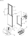
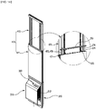
- the fixing unit 370 comprises: a frame body 371 that has a square shape with an opening upward, and that includes: a first connection groove 373 formed on an outer side of the frame body 371 to connect the frame body 371 to a rail of the window frame 30; a roller 374 formed on a bottom side of the first connection groove 373; a slide groove 375 formed on an inner side of the frame body 371 to conjointly engage with edges of the housing unit 310; an inserting hole 377 formed on a top end of the frame body 371, and a mohair 373a formed in the first connection groove 373; a slide wall 470 that is fixed to a top end of the housing unit 310, and covers from the top end of the housing unit 310 to a top portion of the window frame 30.
- the sliding wall 470 comprises: a lower plate 471 that is engaged with the top end of the housing unit 310, and that includes: a guide groove 472 formed in an inner side of the lower plate 471; an insertion bump 473 protruded from and formed in a bottom end of the lower plate 471 to be inserted and connected to the inserting hole 377 of the frame body 371; a second connection groove 474 formed in both lateral sides of the lower plate 471, to connect lower plate 471 to the rail of the window frame 30, and a fixing hole H formed in a top portion of lower plate 471; an upper plate 475 that is sliding-movably connected to the lower plate 471, and that includes: a guide bump 476 formed in an outer side of the upper plate 475 and sliding-movably connected to the guide groove 472; a contact member 477 formed in both lateral sides of the upper plate 475 along the lower plate 471 and meeting with edges of the lower plate 471 for stable sliding motion; and a third connection groove 478 formed in both lateral sides of a top end
- the stopper 570 comprises: a wedge type stopper 571 that is formed at a back side of the lower plate 471 and that is protruded toward the upper plate 475 by an elastic force of an elastic spring 572, and a stopper rail 574 that is formed at a front side of the upper plate 475 to be stuck in and connected to the wedge type stopper 571, and that has a shape where wedge type grooves and bumps are alternatively formed.
- a window-mounted smart air purifier of the present invention it can maintain comfortable indoor environment by improving the indoor air quality.
- the window-mounted smart air purifier also enables to save heating expense by supplying the purified air that is adjusted to have room temperature.
- the window-mounted smart air purifier can provide more comfortable indoor environment through automatic control of the speed of air circulation fan according to concentrations of indoor CO2 and coarse particles.
- the window-mounted smart air purifier can improve energy efficiency using a heat exchanger by transferring the heat of the polluted indoor air that is discharged from indoor to the fresh and purified air that is supplied into indoor.
- the window-mounted smart air purifier can enhance convenience of its installation by enabling it to be installed without perforation in the ceiling or the walls during the installation process.
- FIG. 1 is a front perspective view of a window-mounted smart air purifier according to a preferable embodiment of the present invention.
- FIG. 2 is a back perspective view of a window-mounted smart air purifier according to a preferable embodiment of the present invention.
- FIG. 3 is an exploded perspective view of an operational motion of a spring damper of a window-mounted smart air purifier according to a preferable embodiment of the present invention.
- FIG. 3 is an exploded perspective view of an operational motion of a spring damper of a window-mounted smart air purifier according to a preferable embodiment of the present invention.
- FIG. 3 is an exploded perspective view of an operational motion of a spring damper of a window-mounted smart air purifier according to a preferable embodiment of the present invention.
- FIG. 3 is an exploded perspective view of an operational motion of a spring damper of a window-mounted smart air purifier according to a preferable embodiment of the present invention.
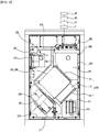
- FIG. 4 is a drawing showing an inner structure of a window-mounted smart air purifier according to a preferable embodiment of the present invention.
- FIG. 5 is an exploded perspective view of a fixing unit of a window-mounted smart air purifier according to a preferable embodiment of the present invention.
- FIG. 6 is an exploded perspective view of a stopper and a binder of a fixing unit of a window-mounted smart air purifier according to a preferable embodiment of the present invention.
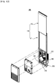
- FIG. 7 is an exploded perspective view of a connection of a housing unit and a fixing unit of a window-mounted smart air purifier according to a preferable embodiment of the present invention.
- a window-mounted smart air purifier 300 comprises a housing unit 310, a first air circulation unit 320, a second air circulation unit 330, an air purification unit 340, a heat exchanger 350, a controller 360, and a fixing unit 370.
- the housing unit 310 is a passage that indoor air and outdoor air move through.
- the housing unit 310 is divided into an indoor air exhaust space 311, an outdoor air introduction space 314, an outdoor air discharge space 316, a central space 318, and an indoor air introduction space 319. In this instance, these spaces are formed to enable air to move around between the spaces freely.
- the window-mounted smart air purifier 300 of the present invention is made of EPP (Expanded Polypropylene) materials, which has an excellent insulation characteristic, to prevent this dew condensation.
- the indoor air exhaust space 311 includes an indoor air exhaust opening 313, and the indoor air introduction space 319 includes an indoor air suction opening 312.
- the outdoor air introduction space 314 includes an outdoor air suction opening 315, and the outdoor discharge space 316 includes a fresh air discharge opening 317.
- the central space 318 is formed so that each of the indoor air and outdoor air passes through an individual pipe intersecting with each other.
- the first air circulation unit 320 is installed in the indoor air exhaust space 311 and forcibly circulates air in order to emit the polluted indoor air to outside.
- the first air circulation unit 320 comprises a first air circulation fan 321, which forcibly circulates the air when external power is on.
- the fist air circulation fan 321 forcibly circulates air so that polluted indoor air introduced through the indoor air suction opening 312 moves toward the indoor air exhaust opening 313.
- the second air circulation unit 330 is installed in the outdoor air discharge space 316 and forcibly circulates air in order to introduce outdoor air to the indoor.
- the second air circulation unit 320 comprises a second air circulation fan 331, which forcibly circulates air when external power is on.
- the second air circulation fan 331 forcibly circulates the air so that outdoor air introduced through the outdoor air suction opening 315 moves toward the outdoor air discharge opening 316.
- the air purification unit 340 purifies the air by filtering impurities contained in the indoor air introduced through the indoor air suction opening 312 and in the outdoor air introduced through the outdoor air suction opening 315.
- the air purification unit 340 is installed at moving paths of the indoor air and the outdoor air.
- the air purification unit 340 comprises a first free filter P1, which is installed between the indoor air introduction space 319 and the central space 318; a second free filter P2, which is installed between the outdoor air introduction space 314 and the central space 318; and a hepa filter and deodorization filter P3.
- the heat exchanger 350 is installed at the central space 318 inside the housing unit 310.
- each of the indoor air and the outdoor air passes through an individual pipe intersecting with each other.
- the heat exchanger 350 is installed on or haves contacts with the pipes of the indoor air and the outdoor air, and exchange heats between the indoor air and the outdoor air.
- the heat exchanger 350 can minimize heat loss occurred during the operation of the window-mounted smart air purifier 300 according to a preferable embodiment of the present invention by adjusting the temperature of the outdoor air supplied into the indoor.
- the controller 360 is installed at a front side of the housing unit 310.
- the controller 360 controls an on/off function and operations of the first air circulation unit 320 and second air circulation unit 330.
- controller 360 may include a timer T. Accordingly, in some embodiments, the controller 360 may further include a filter replacement notification function of the heap filter and deodorization filter P3 and a timer reset function.
- a sensor module which sends a signal to the controller 360, comprises a VOC sensor N1, a CO2 sensor N2, and a coarse particle sensor N3.
- the window-mounted smart air purifier 300 can check air qualities of the outdoor air and the indoor air through the sensors.
- the controller 360 includes a loT function, which exchanges data through a smart device and the internet.
- the loT function enables a user to check various information including an outdoor temperature, an outdoor humidity, an overall outdoor air quality, an outdoor air quality, an overall indoor air quality, an indoor air quality, remote control, and filter replacement time, through the smart device.
- a spring damper 380 is installed at the outdoor air suction opening 315.
- the spring damper 380 opens the suction opening 315 when air circulates, and closes the suction opening 315 when the air stops circulating.
- the controller 360 determines that there are problems in the outdoor air, such as tobacco smoke, fire smoke, stink or offensive odor, which are detected by the VOC sensor P1, and stops an operation of the second air circulation unit 330, the spring damper 380 closes the outdoor air suction opening 315 and thereby the air circulation stops. Meanwhile, when the controller 360 determines that there is no issue, which is detected by the VOC sensor P1, in the outdoor air, and allows an operation of the second air circulation unit 330, a force generated by the air circulation forcibly opens the outdoor air suction opening 315.
- problems in the outdoor air such as tobacco smoke, fire smoke, stink or offensive odor
- the fixing unit 370 is a mean to fix the housing unit 310 between a window frame and a window.
- the fixing unit 370 comprises a frame body 371 and a slide wall 470.
- the frame body 371 is square-shaped, which has an opening upward. Specifically, the frame body 371 has a first connection groove 373 formed on an outer side of the frame body 371 to engage with a rail of the window frame; a roller 374 formed on a bottom side of the first connection groove 373 to make the frame body 371 roll on the rail of the window frame; a slide groove 375 formed on an internal side of the frame body 371 to conjointly engage with the edges of the housing unit 310; and an inserting hole 377 formed on a top end of the frame body 371.
- the first connection groove 373 may further comprise a mohair 373a to keep out draft or impurities such as dust coming through a gap of the window frame.
- the slide wall 470 is fixed to a top end of the housing unit 310.
- the slide wall 470 covers from the top end of the housing unit 310 to the top portion of the window frame 30.
- the slide wall 470 comprises a lower plate 471, an upper plate 475, a stopper 570, and a binder 670.
- the lower plate 471 is engaged with the top end of the housing unit 310.
- the lower plate 471 has a guide groove 472 formed in an inner side; an insertion bump 473 protruded from and formed in a bottom end; a second connection groove 474 formed in both lateral sides, which are engaged with the rail of the window frame 30; and a fixing hole H formed in a top portion.
- the insertion bump 473 is inserted into and connected to the inserting hole 377, thereby the frame body 371 and the lower plate 471 having strong connection.
- the upper plate 475 is sliding-movably connected to the lower plate 471.
- the upper plate 475 includes a guide bump 476 formed in an outer side of the upper plate 475 and sliding-movably connected to the guide groove 472; a contact member 477 formed in both lateral sides of the upper plate 475 along the lower plate 471 and meeting with the edges of the lower plate 471 for stable sliding motion; and a third connection groove 478 formed in both lateral sides of a top portion of the upper plate 475 and connected to the rail of the window frame.
- the contact member 477 is more closely adhered to the lower plate 471, which enables more stable sliding motion of the upper plate 475.
- the stopper 570 is disposed between the lower plate 471 and the upper 475 plate.
- the stopper 570 limits a sliding motion of the upper plate 475 when an adjustable length of the lower plate 471 and the upper plate 475 by the sliding motion of the upper plate 475, reaches to a desired length.
- the stopper 570 comprises a wedge type stopper 571 and a stopper rail 574.
- the wedge type stopper 571 is formed at a back side of the lower plate 471 and can be protruded toward the upper plate 475 by an elastic force of an elastic spring 572.
- stopper rail 574 is formed at a front side of the upper plate 475 in order to be stuck in and connected to the wedge type stopper 571.
- the stopper rail 574 has a shape where wedge type grooves and bumps are alternatively formed.
- the wedge type stopper 571 is inserted to a wedge-shaped groove of the stopper rail 574 and can limit the adjustment of the length of the lower plate 471 and the upper plate 475.
- the wedge type stopper 571 moves along the stopper rail 574 by the external force.
- the wedge type stopper 571 inserted in the wedge-shaped groove of the stopper rail 574 can limit the length adjustment of the lower plate 471 and the upper plate 475.
- the binder 670 is engaged with the fixing hole H, and an end of the binder 670 pressurizes the guide bump 476, which enables the lower plate 471 and the upper plate 475 to be fixed.
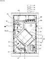
- FIG. 8 is a drawing showing an operational motion of an inner structure of a window-mounted smart air purifier according to a preferable embodiment of the present invention.
- a window-mounted smart air purifier 300 starts to be operated by turning on the controller 360.
- the window-mounted smart air purifier 300 when the window-mounted smart air purifier 300 according to a preferable embodiment of the present invention starts to be operated, the first air circulation fan 321 of the first air circulation unit 320 is operated and emits the polluted indoor air to the outside.
- the polluted indoor air introduced through the indoor air suction opening 312 is emitted through the indoor air suction opening 312, the indoor air introduction space 319, the central space 318, the indoor air exhaust space 311, and the indoor air exhaust opening 313 to the outside.
- the polluted indoor air moving to the central space 318 through the indoor air introduction space 319 is filtered dust and impurities in the air while passing through the first free filter P1 of the air purification unit 340.
- the second air circulation fan 331 of the second air circulation unit 330 is operated, fresh outdoor air is introduced to the indoor.
- the outdoor air introduced through the outdoor air suction opening 315 is introduced to the indoor through the outdoor air suction opening 315, the outdoor air introduction space 314, the central space 318, the indoor air discharge space 316, and the outdoor air discharge opening 317 to the inside.
- the outdoor air moving to the central space 318 through the outdoor air introduction space 314 is filtered dust and impurities in the air while passing through the second free filter P2 and the hepa filter and deodorization filter P3 of the air purification unit 340, which allows fresh air to be supplied into the indoor.
- each of the indoor air and outdoor air passes through an individual pipe intersecting with each other.
- the heat exchanger 350 installed at the central space 317 exchanges heats between the indoor air and the outdoor air, which can minimize heat loss caused by supplying the fresh outdoor air into the indoor.
- a replacement time of the hepa filter and deodorization filter P3 can be notified to a user by the timer T equipped in the controller 360.
- the timer T equipped in the controller 360.
- the user can reset the timer T to receive a notification of the replacement time of a new filter P3.
- the VOC sensor N1, the CO2 sensor N2, and the coarse particle sensor N3 equipped in the controller 360 measure the air qualities of the outdoor air and the indoor air.
- the controller 360 controls operation of the window-mounted smart air purifier 300 by stopping the operation of the window-mounted smart air purifier 300 when the air quality of the indoor air is in a clean level or air quality of the outdoor air is in a bad level, which are measured by the sensors N1, N2, N3; and by driving the operation of the window-mounted smart air purifier 300 when the air quality of the indoor air is in a bad level or air quality of the outdoor air is in a good level, which are measured by the sensors N1, N2, N3.
- the CO2 sensor N2 and the coarse particle sensor N3 may be equipped in the indoor.
- the CO2 sensor N2 and the coarse particle sensor N3 may automatically adjust the amount of ventilation by controlling the speed of the fan according to concentrations of the CO2 and the coarse particles measured indoor.
- the CO2 sensor N2 and the coarse particle sensor N3 may be set in such a way that when pollution is severely high, the fan 321, 331 speeds up, which leads to an increase of ventilation; in contrast, when pollution is low, the fan 321, 331 speed slows down, which leads to a decrease of ventilation.
- the CO2 sensor N2 and the coarse particle sensor N3 may be set in such a way that when pollution is very low, the fan 321, 331 stops; and when pollution gets high, the fan 321, 331 becomes reoperated.
- the VOC sensor N1 may be equipped in the outdoor to detect outdoor odors.
- the controller 360 blocks the outdoor odors by control of the second air circulation fan 331.
- the spring damper 380 in the preferable embodiment of the present invention closes down the outdoor air suction opening 315 by its own elastic force when the controller 360 determines that there are problems in the outdoor air, such as tobacco smoke, fire smoke, stink or offensive odor, which are detected by the VOC sensor N1, and stops an operation of the second air circulation unit 330.
- the controller 360 determines that there is no issue in the outdoor air, which is detected by the VOC sensor P1, and allows an operation of the second air circulation unit 330, a force generated by the air circulation forcibly opens the outdoor air suction opening 315.
- the controller 360 of the window-mounted smart air purifier 300 further comprises a loT function that exchanges data through a smart device and the internet.
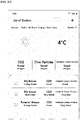
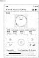
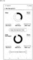
- FIG. 9a is a drawing showing a setting screen of a controller of a window-mounted smart air purifier according to a preferable embodiment of the present invention.
- FIGs. 9b and 9c are drawings showing a setting screen displaying a loT function that is embodied through a controller of a window-mounted smart air purifier according to a preferable embodiment of the present invention.
- the controller 360 of the present invention may be displayed as an indoor air quality display screen, a sleep mode setting screen, a WiFi display screen, a fan display screen, an artificial intelligence display screen, and a power display screen.
- the window-mounted smart air purifier 300 may enable a user to check various information including an outdoor temperature, an outdoor humidity, an overall outdoor air quality, an outdoor air quality, an overall indoor air quality, an indoor air quality, remote control, and filter replacement time, through the smart device, and control operation of the smart air purifier 300.
- FIGs. 10a and 10b are drawings showing an installment of a window-mounted smart air purifier at a window frame according to a preferable embodiment of the present invention.
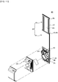
- FIG. 11 is a front exploded perspective view of a window-mounted smart air purifier according to a preferable embodiment of the present invention.
- FIG. 12 is a back exploded perspective view of a window-mounted smart air purifier according to a preferable embodiment of the present invention.
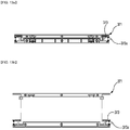
- FIGs. 13a and 13b are a schematical cross-sectional view of a slid wall of a window-mounted smart air purifier according to a preferable embodiment of the present invention.
- the frame body 371 of the fixing unit 370 is installed in a gap between the window frame 30 and the window 31.
- the frame body 371 is connected to a rail (not shown) of the window frame 30 through the first connection groove 373 formed in edges of the frame body 371.
- the roller 374 formed in a bottom side of the frame body 371 is sit on the rail of the window frame 30, and enables the frame body 371 to be moved from side to side by rolling.
- the housing unit 310 is inserted into and combined to the slide groove 375 of the frame body 371.
- the top end of the housing unit 310 is connected to the bottom end of the lower plate 471, which is a part of the slide wall 470.
- the guide groove 472 of the lower plate 471 is connected to the guide bump 476 of the upper plate 475.
- An entire length of the slide wall 470 is adjusted to a desired length by sliding-movement of the upper plate 475.
- the stopper 570 limits further length adjustment of the upper plate 475 and the lower plate 471.
- the wedge type stopper 571 of the slide wall 470 is inserted into the wedge-shaped groove of the stopper rail 574, thereby limiting the length adjustment of the upper plate 475 and the lower plate 471.
- the wedge type stopper 571 moves along the stopper rail 574 by the external force.
- the wedge type stopper 571 inserted into the wedge-shaped groove of the stopper rail 574 can limit the length adjustment of the lower plate 471 and the upper plate 475.
- the lower plate 471 and the upper plate 475 are fixed by the binder 670.
- the binder 670 is engaged with the fixing hole H, and an end of the binder 670 pressurizes the guide bump 476, which enables the lower plate 471 and the upper plate 475 to be fixed.
- the embodiment of the present invention mentioned above is explained according to a sequential installation process of the frame body 371, the lower plate 471, and the upper plate 475, but the present invention is not limited to those installation method.
- the pre-assembled set of the frame body 371, the lower plate 471, and the upper plate 475 may be mounted on the window frame 30, depending on installation places.
- the window-mounted smart air purifier according to a preferable embodiment of the present invention comprising an additional heat exchanger inside can prevent potential heat loss that may be caused by a ventilation process and reduce costs of heating and air conditioning.
- the window-mounted smart air purifier according to a preferable embodiment of the present invention is installed at the window frame and does not need perforation in the ceiling or the wall during the installation process, which can enhance convenience of installation.
- FIG. 14 is a drawing of another embodiment of a slid wall of a window-mounted smart air purifier according to a preferable embodiment of the present invention.
- the window-mounted smart air purifier may further comprise a locking device 700.
- the locking device 700 is formed above the top end of the lower plate 471 and vertically moves along the guide bump 476.
- the locking device 700 prevents the wedge type stopper 571 from moving backward by supporting the wedge type stopper 571.
- the wedge type stopper 571 is fixed to the wedge-shaped groove of the stopper rail 574, which enables the lower plate 471 to have a stable fixed structure.
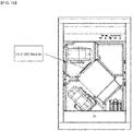
- FIG. 15 is a drawing prefiguratively showing a window-mounted smart air purifier with UV-C LED (Ultraviolet-C Light Emitting Diode) according to a preferable embodiment of the present invention.
- UV-C LED Ultraviolet-C Light Emitting Diode
- the UV-C LED according to embodiments of the present invention may be installed in the central space 318 of the window-mounted smart air purifier, such as an area near the heat exchanger 350.
- the UV-C is a kind of ultraviolet light having a short-wavelength range from about 100nm to about 280 nm.
- FIG. 16 is a drawing prefiguratively showing a UI (User Interface) screen for managing consumables such as a filter, a heat exchanger, and others, of a window-mounted smart air purifier according to a preferable embodiment of the present invention.
- UI User Interface
- Information regarding each consumable may be shown as figures of total usage time, remaining time, replacement period, and others.
- those figures may be shown as graphs so that a user can intuitively know total usage time, remaining time, and others.
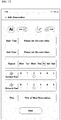
- FIG. 17 is a drawing prefiguratively showing a UI (User Interface) screen for adding reservation of a window-mounted smart air purifier according to a preferable embodiment of the present invention.
- UI User Interface
- a start time, an end time, and repetition for each day of the week can be set, and a fan intensity level of each fan can be adjusted.
Landscapes
- Engineering & Computer Science (AREA)
- General Engineering & Computer Science (AREA)
- Mechanical Engineering (AREA)
- Chemical & Material Sciences (AREA)
- Combustion & Propulsion (AREA)
- Human Computer Interaction (AREA)
- Physics & Mathematics (AREA)
- Fluid Mechanics (AREA)
- Acoustics & Sound (AREA)
- Aviation & Aerospace Engineering (AREA)
- Computer Networks & Wireless Communication (AREA)
- Signal Processing (AREA)
- Ventilation (AREA)
- Air Conditioning Control Device (AREA)
Applications Claiming Priority (2)
| Application Number | Priority Date | Filing Date | Title |
|---|---|---|---|
| KR1020200041474A KR102188972B1 (ko) | 2020-04-06 | 2020-04-06 | 창문 장착형 스마트 환기청정기 |
| PCT/KR2021/002478 WO2021206292A1 (ko) | 2020-04-06 | 2021-02-26 | 창문 장착형 스마트 환기청정기 |
Publications (4)
| Publication Number | Publication Date |
|---|---|
| EP3913293A1 true EP3913293A1 (de) | 2021-11-24 |
| EP3913293A4 EP3913293A4 (de) | 2022-03-30 |
| EP3913293C0 EP3913293C0 (de) | 2024-10-02 |
| EP3913293B1 EP3913293B1 (de) | 2024-10-02 |
Family
ID=73790397
Family Applications (1)
| Application Number | Title | Priority Date | Filing Date |
|---|---|---|---|
| EP21719016.4A Active EP3913293B1 (de) | 2020-04-06 | 2021-02-26 | Fenstermontierbarer intelligenter luftreiniger |
Country Status (5)
| Country | Link |
|---|---|
| US (1) | US11913652B2 (de) |
| EP (1) | EP3913293B1 (de) |
| KR (1) | KR102188972B1 (de) |
| CN (1) | CN113494750B (de) |
| WO (1) | WO2021206292A1 (de) |
Cited By (1)
| Publication number | Priority date | Publication date | Assignee | Title |
|---|---|---|---|---|
| CN114279024A (zh) * | 2021-12-31 | 2022-04-05 | 刘楚悦 | 一种新风净化一体机 |
Families Citing this family (14)
| Publication number | Priority date | Publication date | Assignee | Title |
|---|---|---|---|---|
| CN108548238A (zh) * | 2018-06-13 | 2018-09-18 | 中国矿业大学 | 窗户式空气净化系统 |
| KR102188972B1 (ko) * | 2020-04-06 | 2020-12-10 | 원태연 | 창문 장착형 스마트 환기청정기 |
| KR102377857B1 (ko) * | 2021-03-17 | 2022-03-24 | (주)바이오트코리아 | 높낮이 조절형 비대면 검체 채취 장치 |
| CN113685931A (zh) * | 2021-07-30 | 2021-11-23 | 河南舒岚环保科技有限公司 | 一种便于后期清理内部积尘的窗式新风机及方法 |
| US20230272932A1 (en) * | 2022-02-22 | 2023-08-31 | Samsung Electronics Co., Ltd. | Air cleaner and method for controlling the air cleaner |
| CN114487309B (zh) * | 2022-04-18 | 2022-06-21 | 南通森呼吸环保科技有限公司 | 基于无线传输的分布式室内空气检测装置及方法 |
| USD1042770S1 (en) * | 2022-05-13 | 2024-09-17 | Lg Electronics Inc. | Frame for window air conditioner |
| BE1030553B1 (nl) * | 2022-05-23 | 2023-12-18 | Renson Ventilation Nv | Een ventilatiesysteem voor een residentieel gebouw |
| KR102524895B1 (ko) * | 2022-05-26 | 2023-04-26 | 주식회사 서정 | 자동 환기창 |
| KR102679636B1 (ko) | 2022-06-21 | 2024-06-27 | 윤영상 | 창문형 공기 청정기 |
| WO2024042658A1 (ja) * | 2022-08-24 | 2024-02-29 | 三菱電機株式会社 | 換気システム |
| JP2024110707A (ja) * | 2023-02-03 | 2024-08-16 | 三菱電機株式会社 | 空気清浄機、携帯端末および空気清浄システム |
| CN117060136B (zh) * | 2023-08-21 | 2024-08-30 | 广东浩博特科技股份有限公司 | 一种可统计用电量的智能插座 |
| CN118179197B (zh) * | 2024-04-29 | 2025-01-03 | 唐山亨坤新能源材料有限公司 | 一种环保型磷酸锰铁锂加工用尾气净化装置 |
Family Cites Families (59)
| Publication number | Priority date | Publication date | Assignee | Title |
|---|---|---|---|---|
| US1153067A (en) * | 1915-02-15 | 1915-09-07 | Leslie S Hackney | Ventilating device. |
| US2010808A (en) * | 1933-04-01 | 1935-08-13 | Daniel L Braine | Air conditioner |
| US2036851A (en) * | 1934-02-12 | 1936-04-07 | Edwin F Chittenden | Window ventilator |
| US2218330A (en) * | 1939-01-10 | 1940-10-15 | Bell Telephone Labor Inc | Ventilator |
| US2337325A (en) * | 1941-01-10 | 1943-12-21 | Gen Electric | Air circulating device |
| US2373497A (en) * | 1941-09-08 | 1945-04-10 | Philco Radio & Television Corp | Ventilator |
| US2559495A (en) * | 1947-12-08 | 1951-07-03 | Calkins Robert Walter | Portable air controller |
| US3158083A (en) * | 1961-03-10 | 1964-11-24 | American Air Filter Co | Bypass damper construction |
| US3120340A (en) * | 1961-12-01 | 1964-02-04 | Winton C Strumpell | Blower |
| DE1901361B2 (de) * | 1968-01-29 | 1972-09-14 | Baumann, Ludwig, Niederhelfenschwil, St. Gallen (Schweiz) | Raumventilator mit gleichzeitiger foerderung von zugluft und fortluft, insbesondere mit absperroganenfuer beide luftstroeme |
| US4043141A (en) * | 1976-02-26 | 1977-08-23 | A. C. Manufacturing Company | Air conditioning method and apparatus with humidifier |
| US4458745A (en) * | 1979-02-02 | 1984-07-10 | Josef Gartner & Co. | Device for controlling the temperature of rooms in a building |
| US4460388A (en) * | 1981-07-17 | 1984-07-17 | Nippon Soken, Inc. | Total heat exchanger |
| US5238052A (en) * | 1989-08-17 | 1993-08-24 | Stirling Technology, Inc. | Air to air recouperator |
| US5660605A (en) * | 1995-09-18 | 1997-08-26 | Holmes Products Corp. | Window fan |
| US5660586A (en) * | 1995-09-22 | 1997-08-26 | Duracraft Corporation | Variable discharge window fan |
| US5730651A (en) * | 1996-08-08 | 1998-03-24 | Lakewood Engineering And Manufacturing Co. | Independent directional-flow air ducts for low-profile window fan |
| US5902183A (en) * | 1996-11-15 | 1999-05-11 | D'souza; Melanius | Process and apparatus for energy conservation in buildings using a computer controlled ventilation system |
| US6328095B1 (en) * | 2000-03-06 | 2001-12-11 | Honeywell International Inc. | Heat recovery ventilator with make-up air capability |
| US6494940B1 (en) * | 2000-09-29 | 2002-12-17 | Hamilton Beach/Proctor-Silex, Inc. | Air purifier |
| JP3654349B2 (ja) | 2001-07-09 | 2005-06-02 | ソニー株式会社 | コンテンツ嗜好度算出方法およびコンテンツ受信装置 |
| NL1020481C1 (nl) * | 2002-04-26 | 2003-10-31 | Oxycell Holding Bv | Enthalpiewisselaar, uitgevoerd als kozijnstijl. |
| US6800022B2 (en) * | 2003-02-19 | 2004-10-05 | Delphi Technologies, Inc. | Inlet air control method for a vehicle HVAC system having an air quality sensor |
| EP1486637B1 (de) * | 2003-06-12 | 2009-08-05 | Lidartech Co., Ltd. | Fenster mit Lüftungsvorrichtung |
| ES2245875B1 (es) * | 2004-03-26 | 2006-11-16 | Joaquin Espuelas Peñalva | Proceso de fabricacion y filtro de tejido no tejido y/o de laminas o estructuras inyectadas filtrantes obtenidos por dicho proceso para la filtracion y eliminacion de la legionella pneumofila. |
| KR100714719B1 (ko) * | 2004-12-03 | 2007-05-04 | 삼성전자주식회사 | 이동하면서 공기를 청정하는 방법 및 장치 |
| US7311740B2 (en) * | 2005-02-14 | 2007-12-25 | Honeywell International, Inc. | Snap acting split flapper valve |
| KR100617080B1 (ko) * | 2005-02-15 | 2006-08-30 | 엘지전자 주식회사 | 공기조화 시스템 및 그 제어방법 |
| KR100728339B1 (ko) * | 2005-12-09 | 2007-06-13 | 주식회사 대우일렉트로닉스 | 폐열회수 환기장치 |
| US7966837B2 (en) * | 2007-03-28 | 2011-06-28 | Madina, LLC | Air-conditioning register assembly and method |
| CA2602737A1 (en) * | 2007-09-14 | 2009-03-14 | Air Tech Equipment Ltd. | Dehumidifying system |
| US8155797B2 (en) * | 2009-08-12 | 2012-04-10 | James Wiese | Window fan control system and method of controlling a fan unit |
| US8123142B2 (en) * | 2009-08-20 | 2012-02-28 | Cislo Daniel M | Solar powered smart ventilation system |
| JP5999353B2 (ja) * | 2012-12-10 | 2016-09-28 | パナソニックIpマネジメント株式会社 | 空調制御システム |
| CN105134049A (zh) * | 2015-09-04 | 2015-12-09 | 周国增 | 具有空气净化功能的窗框 |
| CN105182785B (zh) * | 2015-09-30 | 2018-05-25 | 北京格瑞那环能技术有限责任公司 | 一种智能家居系统 |
| CN205191775U (zh) * | 2015-12-11 | 2016-04-27 | 四川长虹空调有限公司 | 具备监控滤网洁净度功能的智能空气净化器 |
| KR101824148B1 (ko) * | 2016-03-03 | 2018-01-31 | 주식회사 경동나비엔 | 환기장치 |
| KR101778736B1 (ko) * | 2016-09-29 | 2017-09-14 | 주식회사 미지에너텍 | 공기 청정기의 제어 방법 및 장치 |
| KR20180045896A (ko) * | 2016-10-24 | 2018-05-08 | 주식회사 리상 | 공기 정화 및 열교환 기능을 구비한 창문 환기장치 |
| CN206531233U (zh) * | 2017-02-17 | 2017-09-29 | 银成化学株式会社 | 地面式热回收换气装置 |
| KR101812447B1 (ko) * | 2017-04-14 | 2017-12-26 | 윤병석 | 환기장치 |
| KR101828587B1 (ko) * | 2017-06-26 | 2018-02-13 | (주)센도리 | 먼지제거기능을 구비한 공조장치 |
| KR101939686B1 (ko) * | 2017-06-30 | 2019-04-12 | 주식회사 현대엘앤씨 | IoT를 이용한 창호 일체형 기계환기 장치 제어시스템 |
| CN107401800A (zh) * | 2017-07-17 | 2017-11-28 | 深圳沃海森科技有限公司 | 设置于新风机上的环保节能空调系统 |
| EP3701197A1 (de) * | 2017-10-26 | 2020-09-02 | Koninklijke Philips N.V. | Intelligente luftreinigung |
| KR102022616B1 (ko) * | 2017-11-30 | 2019-11-26 | 배진수 | 창문 장착형 공기청정장치 및 공기청정방법 |
| KR102052638B1 (ko) * | 2018-01-29 | 2019-12-05 | 이윤미 | 덕트형 다기능 공기청정기 및 그 운용방법 |
| KR101965770B1 (ko) * | 2018-02-06 | 2019-04-04 | 김우진 | 창틀 장착형 환기시스템 |
| CN108534333A (zh) * | 2018-03-16 | 2018-09-14 | 青岛海尔空调器有限总公司 | 用于双向进出风管的热交换芯 |
| CN108361874A (zh) * | 2018-03-23 | 2018-08-03 | 上海交通大学 | 热交换新风净化器 |
| KR102381534B1 (ko) * | 2018-03-28 | 2022-03-31 | 김우진 | 창틀 장착형 환기시스템 |
| KR20190117897A (ko) * | 2018-04-09 | 2019-10-17 | 박준흥 | 환기 겸용 공기청정기 |
| CN108917081A (zh) * | 2018-05-31 | 2018-11-30 | 安徽科清净化科技有限公司 | 一种新型建筑通风用新风机 |
| KR102203801B1 (ko) * | 2018-06-15 | 2021-01-18 | (주)공존에스앤티 | 창문형 스마트 환기청정기 |
| KR101956632B1 (ko) * | 2018-07-16 | 2019-03-11 | (주)센도리 | 사각지대의 먼지 제거가 가능한 공조기용 필터 |
| KR102039071B1 (ko) * | 2019-03-26 | 2019-11-01 | 주식회사 브랜뉴인터내셔널 | 설치 및 탈결합이 용이한 창틀거치형 공기청정기 |
| KR102060633B1 (ko) * | 2019-07-24 | 2019-12-30 | 서진공조(주) | 공기 청정 기술이 적용된 공기 순환 시스템 |
| KR102188972B1 (ko) * | 2020-04-06 | 2020-12-10 | 원태연 | 창문 장착형 스마트 환기청정기 |
-
2020
- 2020-04-06 KR KR1020200041474A patent/KR102188972B1/ko active Active
-
2021
- 2021-02-26 WO PCT/KR2021/002478 patent/WO2021206292A1/ko not_active Ceased
- 2021-02-26 EP EP21719016.4A patent/EP3913293B1/de active Active
- 2021-03-31 CN CN202110348301.3A patent/CN113494750B/zh active Active
- 2021-04-05 US US17/222,167 patent/US11913652B2/en active Active
Cited By (2)
| Publication number | Priority date | Publication date | Assignee | Title |
|---|---|---|---|---|
| CN114279024A (zh) * | 2021-12-31 | 2022-04-05 | 刘楚悦 | 一种新风净化一体机 |
| CN114279024B (zh) * | 2021-12-31 | 2024-02-13 | 深圳英创能源环境技术有限公司 | 一种新风净化一体机 |
Also Published As
| Publication number | Publication date |
|---|---|
| WO2021206292A1 (ko) | 2021-10-14 |
| CN113494750A (zh) | 2021-10-12 |
| US11913652B2 (en) | 2024-02-27 |
| US20210310671A1 (en) | 2021-10-07 |
| KR102188972B1 (ko) | 2020-12-10 |
| CN113494750B (zh) | 2022-12-20 |
| EP3913293A4 (de) | 2022-03-30 |
| EP3913293C0 (de) | 2024-10-02 |
| EP3913293B1 (de) | 2024-10-02 |
Similar Documents
| Publication | Publication Date | Title |
|---|---|---|
| US11913652B2 (en) | Window-mounted smart air purifier | |
| CN207006407U (zh) | 一种高效新风机 | |
| CN206468252U (zh) | 具有热交换和空气净化功能的窗户通风系统 | |
| CN111288583B (zh) | 一种多功能新风净化机及运行控制方法 | |
| CN111895509A (zh) | 一种空调的室内机及空调 | |
| KR102383783B1 (ko) | 기상정보를 연동한 에너지절감형 공기청정 클린 환기시스템 | |
| KR102081237B1 (ko) | 환기 및 에너지 절감형 공기청정기 | |
| CN108302685B (zh) | 具有内部空气的循环、排出和吸入功能的空气循环系统 | |
| CN2901129Y (zh) | 反吹清灰式室内空气换气机 | |
| KR20180127595A (ko) | 복합 환경제어용 공기조화기 | |
| KR100587359B1 (ko) | 공기청정장치 일체형 환기시스템 | |
| KR100556066B1 (ko) | 수요 대응 제어형 공조 시스템 | |
| KR100580288B1 (ko) | 살균 및 온도조절 기능을 구비한 환기용 흡기유니트 | |
| KR101808120B1 (ko) | 실별 제어가 가능한 공기청정 시스템 | |
| CN111520839B (zh) | 一种窗式新风净化器 | |
| KR101851676B1 (ko) | 폐열 회수 환기장치 | |
| KR100587315B1 (ko) | 환기시스템 | |
| CN2447672Y (zh) | 空气净化加湿器 | |
| KR20220006427A (ko) | 공기순환기의 필터수명 연장구조 | |
| KR102067232B1 (ko) | 벽부형 전열교환기 | |
| KR20050080286A (ko) | 공기청정장치 일체형 환기시스템 | |
| KR100587314B1 (ko) | 환기시스템 | |
| CN208296037U (zh) | 柜式空调室内机 | |
| KR100736707B1 (ko) | 환기 열회수장치 및 방법 | |
| JPH11248239A (ja) | 空調システムにおける床置き式空気循環装置 |
Legal Events
| Date | Code | Title | Description |
|---|---|---|---|
| STAA | Information on the status of an ep patent application or granted ep patent |
Free format text: STATUS: UNKNOWN |
|
| STAA | Information on the status of an ep patent application or granted ep patent |
Free format text: STATUS: THE INTERNATIONAL PUBLICATION HAS BEEN MADE |
|
| PUAI | Public reference made under article 153(3) epc to a published international application that has entered the european phase |
Free format text: ORIGINAL CODE: 0009012 |
|
| STAA | Information on the status of an ep patent application or granted ep patent |
Free format text: STATUS: REQUEST FOR EXAMINATION WAS MADE |
|
| 17P | Request for examination filed |
Effective date: 20210426 |
|
| AK | Designated contracting states |
Kind code of ref document: A1 Designated state(s): AL AT BE BG CH CY CZ DE DK EE ES FI FR GB GR HR HU IE IS IT LI LT LU LV MC MK MT NL NO PL PT RO RS SE SI SK SM TR |
|
| A4 | Supplementary search report drawn up and despatched |
Effective date: 20220228 |
|
| RIC1 | Information provided on ipc code assigned before grant |
Ipc: F24F 110/66 20180101ALI20220222BHEP Ipc: F24F 110/64 20180101ALI20220222BHEP Ipc: F24F 110/70 20180101ALI20220222BHEP Ipc: F24F 110/22 20180101ALI20220222BHEP Ipc: F24F 110/12 20180101ALI20220222BHEP Ipc: F24F 11/523 20180101ALI20220222BHEP Ipc: F24F 8/108 20210101ALI20220222BHEP Ipc: F24F 1/031 20190101ALI20220222BHEP Ipc: F24F 13/10 20060101ALI20220222BHEP Ipc: F24F 13/28 20060101ALI20220222BHEP Ipc: F24F 12/00 20060101ALI20220222BHEP Ipc: F24F 11/56 20180101ALI20220222BHEP Ipc: F24F 11/61 20180101ALI20220222BHEP Ipc: F24F 11/77 20180101ALI20220222BHEP Ipc: F24F 8/10 20210101ALI20220222BHEP Ipc: F24F 7/06 20060101AFI20220222BHEP |
|
| DAV | Request for validation of the european patent (deleted) | ||
| DAX | Request for extension of the european patent (deleted) | ||
| STAA | Information on the status of an ep patent application or granted ep patent |
Free format text: STATUS: EXAMINATION IS IN PROGRESS |
|
| 17Q | First examination report despatched |
Effective date: 20230712 |
|
| GRAP | Despatch of communication of intention to grant a patent |
Free format text: ORIGINAL CODE: EPIDOSNIGR1 |
|
| STAA | Information on the status of an ep patent application or granted ep patent |
Free format text: STATUS: GRANT OF PATENT IS INTENDED |
|
| INTG | Intention to grant announced |
Effective date: 20240515 |
|
| GRAS | Grant fee paid |
Free format text: ORIGINAL CODE: EPIDOSNIGR3 |
|
| GRAA | (expected) grant |
Free format text: ORIGINAL CODE: 0009210 |
|
| STAA | Information on the status of an ep patent application or granted ep patent |
Free format text: STATUS: THE PATENT HAS BEEN GRANTED |
|
| AK | Designated contracting states |
Kind code of ref document: B1 Designated state(s): AL AT BE BG CH CY CZ DE DK EE ES FI FR GB GR HR HU IE IS IT LI LT LU LV MC MK MT NL NO PL PT RO RS SE SI SK SM TR |
|
| REG | Reference to a national code |
Ref country code: GB Ref legal event code: FG4D |
|
| REG | Reference to a national code |
Ref country code: CH Ref legal event code: EP |
|
| REG | Reference to a national code |
Ref country code: IE Ref legal event code: FG4D |
|
| REG | Reference to a national code |
Ref country code: DE Ref legal event code: R096 Ref document number: 602021019590 Country of ref document: DE |
|
| U01 | Request for unitary effect filed |
Effective date: 20241104 |
|
| U07 | Unitary effect registered |
Designated state(s): AT BE BG DE DK EE FI FR IT LT LU LV MT NL PT RO SE SI Effective date: 20241113 |
|
| PG25 | Lapsed in a contracting state [announced via postgrant information from national office to epo] |
Ref country code: IS Free format text: LAPSE BECAUSE OF FAILURE TO SUBMIT A TRANSLATION OF THE DESCRIPTION OR TO PAY THE FEE WITHIN THE PRESCRIBED TIME-LIMIT Effective date: 20250202 Ref country code: HR Free format text: LAPSE BECAUSE OF FAILURE TO SUBMIT A TRANSLATION OF THE DESCRIPTION OR TO PAY THE FEE WITHIN THE PRESCRIBED TIME-LIMIT Effective date: 20241002 |
|
| PG25 | Lapsed in a contracting state [announced via postgrant information from national office to epo] |
Ref country code: ES Free format text: LAPSE BECAUSE OF FAILURE TO SUBMIT A TRANSLATION OF THE DESCRIPTION OR TO PAY THE FEE WITHIN THE PRESCRIBED TIME-LIMIT Effective date: 20241002 |
|
| PG25 | Lapsed in a contracting state [announced via postgrant information from national office to epo] |
Ref country code: NO Free format text: LAPSE BECAUSE OF FAILURE TO SUBMIT A TRANSLATION OF THE DESCRIPTION OR TO PAY THE FEE WITHIN THE PRESCRIBED TIME-LIMIT Effective date: 20250102 |
|
| PG25 | Lapsed in a contracting state [announced via postgrant information from national office to epo] |
Ref country code: GR Free format text: LAPSE BECAUSE OF FAILURE TO SUBMIT A TRANSLATION OF THE DESCRIPTION OR TO PAY THE FEE WITHIN THE PRESCRIBED TIME-LIMIT Effective date: 20250103 |
|
| PG25 | Lapsed in a contracting state [announced via postgrant information from national office to epo] |
Ref country code: CZ Free format text: LAPSE BECAUSE OF FAILURE TO SUBMIT A TRANSLATION OF THE DESCRIPTION OR TO PAY THE FEE WITHIN THE PRESCRIBED TIME-LIMIT Effective date: 20241002 Ref country code: PL Free format text: LAPSE BECAUSE OF FAILURE TO SUBMIT A TRANSLATION OF THE DESCRIPTION OR TO PAY THE FEE WITHIN THE PRESCRIBED TIME-LIMIT Effective date: 20241002 |
|
| PG25 | Lapsed in a contracting state [announced via postgrant information from national office to epo] |
Ref country code: RS Free format text: LAPSE BECAUSE OF FAILURE TO SUBMIT A TRANSLATION OF THE DESCRIPTION OR TO PAY THE FEE WITHIN THE PRESCRIBED TIME-LIMIT Effective date: 20250102 |
|
| PG25 | Lapsed in a contracting state [announced via postgrant information from national office to epo] |
Ref country code: SM Free format text: LAPSE BECAUSE OF FAILURE TO SUBMIT A TRANSLATION OF THE DESCRIPTION OR TO PAY THE FEE WITHIN THE PRESCRIBED TIME-LIMIT Effective date: 20241002 |
|
| PG25 | Lapsed in a contracting state [announced via postgrant information from national office to epo] |
Ref country code: SK Free format text: LAPSE BECAUSE OF FAILURE TO SUBMIT A TRANSLATION OF THE DESCRIPTION OR TO PAY THE FEE WITHIN THE PRESCRIBED TIME-LIMIT Effective date: 20241002 |
|
| PLBE | No opposition filed within time limit |
Free format text: ORIGINAL CODE: 0009261 |
|
| STAA | Information on the status of an ep patent application or granted ep patent |
Free format text: STATUS: NO OPPOSITION FILED WITHIN TIME LIMIT |
|
| 26N | No opposition filed |
Effective date: 20250703 |
|
| PG25 | Lapsed in a contracting state [announced via postgrant information from national office to epo] |
Ref country code: MC Free format text: LAPSE BECAUSE OF FAILURE TO SUBMIT A TRANSLATION OF THE DESCRIPTION OR TO PAY THE FEE WITHIN THE PRESCRIBED TIME-LIMIT Effective date: 20241002 |
|
| REG | Reference to a national code |
Ref country code: CH Ref legal event code: PL |
|
| U90 | Renewal fees not paid: noting of loss of rights |
Free format text: RENEWAL FEE NOT PAID FOR YEAR 05 Effective date: 20250918 |
|
| PG25 | Lapsed in a contracting state [announced via postgrant information from national office to epo] |
Ref country code: CH Free format text: LAPSE BECAUSE OF NON-PAYMENT OF DUE FEES Effective date: 20250228 |
|
| GBPC | Gb: european patent ceased through non-payment of renewal fee |
Effective date: 20250226 |