EP3911211B1 - Sac d'aspirateur et aspirateur - Google Patents
Sac d'aspirateur et aspirateur Download PDFInfo
- Publication number
- EP3911211B1 EP3911211B1 EP20703725.0A EP20703725A EP3911211B1 EP 3911211 B1 EP3911211 B1 EP 3911211B1 EP 20703725 A EP20703725 A EP 20703725A EP 3911211 B1 EP3911211 B1 EP 3911211B1
- Authority
- EP
- European Patent Office
- Prior art keywords
- vacuum cleaner
- inflow opening
- cleaner bag
- layers
- bag
- Prior art date
- Legal status (The legal status is an assumption and is not a legal conclusion. Google has not performed a legal analysis and makes no representation as to the accuracy of the status listed.)
- Active
Links
- 239000000463 material Substances 0.000 claims description 15
- 238000007789 sealing Methods 0.000 claims description 3
- 239000004745 nonwoven fabric Substances 0.000 claims description 2
- 239000010410 layer Substances 0.000 claims 5
- 239000002356 single layer Substances 0.000 claims 1
- 239000000428 dust Substances 0.000 description 3
- 239000000853 adhesive Substances 0.000 description 2
- 230000001070 adhesive effect Effects 0.000 description 2
- 239000013013 elastic material Substances 0.000 description 2
- 239000006260 foam Substances 0.000 description 2
- 239000002245 particle Substances 0.000 description 2
- 238000000926 separation method Methods 0.000 description 2
- 230000003749 cleanliness Effects 0.000 description 1
- 239000011362 coarse particle Substances 0.000 description 1
- 239000011888 foil Substances 0.000 description 1
- 230000000284 resting effect Effects 0.000 description 1
- 230000000717 retained effect Effects 0.000 description 1
- 230000000007 visual effect Effects 0.000 description 1
Images


Classifications
-
- A—HUMAN NECESSITIES
- A47—FURNITURE; DOMESTIC ARTICLES OR APPLIANCES; COFFEE MILLS; SPICE MILLS; SUCTION CLEANERS IN GENERAL
- A47L—DOMESTIC WASHING OR CLEANING; SUCTION CLEANERS IN GENERAL
- A47L9/00—Details or accessories of suction cleaners, e.g. mechanical means for controlling the suction or for effecting pulsating action; Storing devices specially adapted to suction cleaners or parts thereof; Carrying-vehicles specially adapted for suction cleaners
- A47L9/10—Filters; Dust separators; Dust removal; Automatic exchange of filters
- A47L9/14—Bags or the like; Rigid filtering receptacles; Attachment of, or closures for, bags or receptacles
- A47L9/1427—Means for mounting or attaching bags or filtering receptacles in suction cleaners; Adapters
-
- A—HUMAN NECESSITIES
- A47—FURNITURE; DOMESTIC ARTICLES OR APPLIANCES; COFFEE MILLS; SPICE MILLS; SUCTION CLEANERS IN GENERAL
- A47L—DOMESTIC WASHING OR CLEANING; SUCTION CLEANERS IN GENERAL
- A47L9/00—Details or accessories of suction cleaners, e.g. mechanical means for controlling the suction or for effecting pulsating action; Storing devices specially adapted to suction cleaners or parts thereof; Carrying-vehicles specially adapted for suction cleaners
- A47L9/10—Filters; Dust separators; Dust removal; Automatic exchange of filters
- A47L9/14—Bags or the like; Rigid filtering receptacles; Attachment of, or closures for, bags or receptacles
- A47L9/1481—Means for removing bags in suction cleaners, e.g. ejecting means; Means for exchanging bags
-
- B—PERFORMING OPERATIONS; TRANSPORTING
- B01—PHYSICAL OR CHEMICAL PROCESSES OR APPARATUS IN GENERAL
- B01D—SEPARATION
- B01D39/00—Filtering material for liquid or gaseous fluids
- B01D39/08—Filter cloth, i.e. woven, knitted or interlaced material
-
- B—PERFORMING OPERATIONS; TRANSPORTING
- B01—PHYSICAL OR CHEMICAL PROCESSES OR APPARATUS IN GENERAL
- B01D—SEPARATION
- B01D46/00—Filters or filtering processes specially modified for separating dispersed particles from gases or vapours
- B01D46/02—Particle separators, e.g. dust precipitators, having hollow filters made of flexible material
-
- B—PERFORMING OPERATIONS; TRANSPORTING
- B01—PHYSICAL OR CHEMICAL PROCESSES OR APPARATUS IN GENERAL
- B01D—SEPARATION
- B01D2239/00—Aspects relating to filtering material for liquid or gaseous fluids
- B01D2239/06—Filter cloth, e.g. knitted, woven non-woven; self-supported material
- B01D2239/0604—Arrangement of the fibres in the filtering material
- B01D2239/0618—Non-woven
-
- B—PERFORMING OPERATIONS; TRANSPORTING
- B01—PHYSICAL OR CHEMICAL PROCESSES OR APPARATUS IN GENERAL
- B01D—SEPARATION
- B01D2239/00—Aspects relating to filtering material for liquid or gaseous fluids
- B01D2239/06—Filter cloth, e.g. knitted, woven non-woven; self-supported material
- B01D2239/065—More than one layer present in the filtering material
-
- B—PERFORMING OPERATIONS; TRANSPORTING
- B01—PHYSICAL OR CHEMICAL PROCESSES OR APPARATUS IN GENERAL
- B01D—SEPARATION
- B01D2271/00—Sealings for filters specially adapted for separating dispersed particles from gases or vapours
- B01D2271/02—Gaskets, sealings
-
- B—PERFORMING OPERATIONS; TRANSPORTING
- B01—PHYSICAL OR CHEMICAL PROCESSES OR APPARATUS IN GENERAL
- B01D—SEPARATION
- B01D2275/00—Filter media structures for filters specially adapted for separating dispersed particles from gases or vapours
- B01D2275/10—Multiple layers
-
- B—PERFORMING OPERATIONS; TRANSPORTING
- B01—PHYSICAL OR CHEMICAL PROCESSES OR APPARATUS IN GENERAL
- B01D—SEPARATION
- B01D2279/00—Filters adapted for separating dispersed particles from gases or vapours specially modified for specific uses
- B01D2279/55—Filters adapted for separating dispersed particles from gases or vapours specially modified for specific uses for cleaning appliances, e.g. suction cleaners
Definitions
- the present invention relates to a vacuum cleaner bag with two layers of filter material, which are connected to one another on at least three sides, with an inflow opening being formed at least in some areas on a fourth side between the two layers, into which a nozzle can be inserted for connection to a vacuum cleaner, and a spring element is provided at the inflow opening, which biases the two layers into a closed position, and a vacuum cleaner.
- the EP 1 915 939 B1 discloses a filter bag for a vacuum cleaner, which is designed as a flat bag and in which two layers of filter material are welded together at the edge. An inflow opening is punched out in one of the layers, on which a holder plate for releasably fixing the vacuum cleaner bag in a vacuum cleaner is arranged. When inflated, the vacuum cleaner bag has a pillow shape, which is why the vacuum cleaner bag is poorly suited for small vacuum cleaners, such as cordless sticks, despite good filter performance.
- the DE 10 2017 209 154 A1 discloses a handheld vacuum cleaner that has a separator that works according to the centrifugal force principle. Such separators are only suitable for separating coarse particles and only produce visual cleanliness because smaller particles are not retained. Despite these disadvantages, vacuum cleaners are available on the market that only have a low suction power and a low separation efficiency for smaller particles, but have a particularly compact design thanks to the use of a small battery-operated suction unit. Such a vacuum cleaner is used, for example, in the DE 10 2016 105 475 A1 described.
- DE 926 988 discloses a dust container for a vacuum cleaner, in which a paper bag is held together at the bag mouth via a pair of leaf springs which are secured to one another at their free ends via clamps. This also shows a similar design with a two-part leaf spring US 2,158,955 .
- two layers of filter material are connected to one another at the edge on at least three sides.
- the connection can either be made via a folded edge or a connecting seam, for example an adhesive seam or weld seam.
- the interior formed in this way is accessible via an inflow opening, which is formed at least in some areas on a fourth side between the two layers so that a connector can be inserted for connection to a vacuum cleaner.
- On the fourth side either no connecting seam can be provided at all, or this is only arranged over part of the length of the fourth side, and another part is unconnected and forms an inflow opening.
- This allows the vacuum cleaner bag to be better adapted to elongated, compact chambers in a vacuum cleaner.
- the production of the vacuum cleaner bag is simple, as there is no need to punch out an inlet opening in one of the two layers of filter material and attach the holding plate.
- a spring element is provided at the inflow opening.
- the spring element is inserted into a seam formed on the two layers at the inflow opening.
- the spring element pretensions the two layers into a closed position, so that after the vacuum cleaner bag has been removed from a nozzle, the inflow opening is closed via the spring element.
- a rope or a tensioning element can be provided as a closure element, by means of which the inflow opening can be closed after it has been removed from a nozzle of a vacuum cleaner.
- a Velcro fastener, profile fastener with two interlocking profiles, snap fasteners, rivets, magnets or a terminal strip can also be used as a closure element.
- self-closing closures as are known from foil bags, can also be used.
- a crimp clamp or an annular spring can also be used as a closure element.
- the spring element provided at the inflow opening of the vacuum cleaner bag is designed as a leaf spring.
- the leaf spring has a kink in the form of a bend of approximately 180° at one end of the inflow opening.
- the inflow opening can be biased into the closed position via a single spring element.
- the leaf spring is captively arranged in the hem of the vacuum cleaner bag.
- the inflow opening can extend completely over the length on the fourth side.
- This enables the design of rather elongated vacuum cleaner bags which, when viewed from above, have two long sides and two narrow sides, with the inflow opening being provided on one narrow side.
- the long sides can have a length that is at least three times longer, preferably at least four times longer, than the length of the narrow sides.
- a surrounding chamber of a vacuum cleaner can also be essentially hose-shaped or tubular.
- the filter material can have a sealing layer on the inside of the inflow opening, for example a fluffy fleece or a strip made of an elastic material, such as foam.
- the vacuum cleaner bag can also be made from a non-woven material, in particular a single- or multi-layer non-woven material.
- the vacuum cleaner bag is preferably inserted into a chamber of a vacuum cleaner with a powered fan, in particular a vacuum cleaner powered electrically by batteries.
- the vacuum cleaner can have a holding device that fixes the vacuum cleaner bag in the area of the inflow opening.
- the vacuum cleaner bag is attached to a nozzle in the vacuum cleaner with the inlet opening. Holding means such as grooves, grooves, ribs, magnets or clamping elements can be provided on this connector for better fixation.
- the nozzle of the vacuum cleaner for attaching the vacuum cleaner bag preferably has a contour that deviates from the circular shape in cross section.
- the cross-sectional shape can be essentially oval, although the two ends on the narrow sides of the oval can also taper to a point in order to optimize the seal between the nozzle and the vacuum cleaner bag.
- a mechanical ejector is preferably provided on the vacuum cleaner, by means of which the vacuum cleaner bag can be removed from the nozzle on the vacuum cleaner. This allows the vacuum cleaner bag to be ejected from an opening in the chamber without the user having to touch it. Alternatively, the vacuum cleaner bag can also be removed from the nozzle by hand and disposed of.
- a vacuum cleaner bag 1 comprises two layers 2 made of filter material, in particular made of a single or multi-layer nonwoven fabric or paper, whereby the layers 2 can be designed to be congruent. Seen in plan view, each layer 2 is rectangular, with two opposing narrow sides 3 and 4 and two long sides 5. The length of the long sides 5 is significantly longer than the length of the narrow sides 3 and 4, preferably at least three times as long.
- the vacuum cleaner bag 1 is closed on three sides to form an interior, with the two layers 2 made of filter material being connected either via a folded edge or a connecting seam 6.
- the connecting seam 6 can be designed as a weld seam or adhesive seam.
- the narrow side 4 an upper layer 2 and a lower layer 20 are not connected, so that an inflow opening 9 is formed between the two layers 2 and 20.
- a hem 7 is formed, which can be produced by folding the filter material and fixing it with a seam 8.
- the seam 7 extends on the layer 2 and the layer 20 made of filter material and forms a channel into which a closure element can be inserted.
- a spring element is provided as a closure element, which biases the two layers 2 and 20 into a closed position.
- a metallic leaf spring can be used that has a kink in the area of one of the ends of a long side 5.
- another closure element such as a rope or a plastic clip, can also be used.
- the vacuum cleaner bag 1 is shown in section, and it can be seen that the layer 2 and the layer 20 surround an interior in which dust can be collected.
- the inflow opening 9 is in a closed position in which the two layers 2 and 20 contact each other, as shown schematically.
- the closed position is held by a spring element 10, which is designed as a leaf spring, which has a kink or bend of approximately 180 ° in the area of a long side 5.
- the spring element 10 is held in the seam 7 at the inflow opening 9.
- the vacuum cleaner bag 1 In order to arrange the vacuum cleaner bag 1 in a chamber of a vacuum cleaner, it is placed on a nozzle 11 which has one or more tips 12 on its front which can be inserted into the inflow opening 9.
- FIG 3 the vacuum cleaner bag 1 is shown with the inserted nozzle 11, with the layers 2 and 20 of the vacuum cleaner bag resting on the nozzle 11.
- the spring element 10 presses the layers 2 and 20 against the socket 11 and thus ensures a seal.
- a sealing element can be provided on the layers 2 and 20 made of filter material, for example a bulky nonwoven material, a strip of foam or another elastic material.
- the vacuum cleaner bag 1 When the vacuum cleaner bag 1 is filled with dust, it can be removed from the nozzle 11 manually or using a scraper, whereby this Spring element 10 ensures automatic closing when the vacuum cleaner bag is removed. The vacuum cleaner bag 1 can then be disposed of.
- a modified vacuum cleaner bag 1' which has an upper layer 2' and a congruent lower layer, which are connected to one another on two long sides 5 and a narrow side 3' via a seam or a folded edge.
- a seam 40 is also provided on the further narrow side, which extends over part of the length of the narrow side, for example between 20% to 80% of the length of the narrow side.
- An unconnected area of the layers 2 'on the fourth narrow side forms an inflow opening 9 into which a nozzle 11 of a vacuum cleaner can be inserted.
- the inflow opening 9 comprises a seam 7, on which a spring element 10 is arranged in order to bias the inflow opening 9 into a sealed position, as in the exemplary embodiment of FIG Figure 1 was explained.
- Figure 5 shows a vacuum cleaner bag 1' similar to Figure 4 , wherein the inflow opening 9 is arranged centrally on a narrow side and a seam 40 is provided on opposite sides of the inflow opening 9.
- An unconnected area of the layers 2 'on the narrow side forms the inflow opening 9, which is surrounded by a seam 7 with a spring element 10.
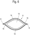
- FIG. 6 is a sectional view through the connector 11 in the area of the inflow opening 9, but without the spring element 10 and the seam 7.
- the connector 11 has a tubular channel 13, which is essentially oval in cross section and has a greater extent in a longitudinal direction than vertical has this.
- the nozzle 11 has two opposite wall sections 14 with a smaller radius of curvature than two tips 15, which are arranged adjacent to the connecting seams 6 on the long sides 5. This allows the vacuum cleaner bag 1 or 1' to be better sealed in the area of the inflow opening 9.
- the vacuum cleaner bag 1 can be used in particular in a vacuum cleaner with an elongated housing shape, as is known from battery-operated vacuum cleaners, which are also referred to as “battery sticks”.
Landscapes
- Engineering & Computer Science (AREA)
- Mechanical Engineering (AREA)
- Chemical & Material Sciences (AREA)
- Chemical Kinetics & Catalysis (AREA)
- Textile Engineering (AREA)
- Filters For Electric Vacuum Cleaners (AREA)
Claims (12)
- Sac d'aspirateur (1, 1') compose de deux couches (2, 2', 20) en un matériau de filtre et qui sont reliées entre elles au bord sur au moins trois côtés (3, 5) pour former un volume intérieur, un quatrième côté (4) étant formé entre les deux couches (2, 2', 20) au moins par zones avec un orifice d'entrée (9) dans lequel on engage un embout (11) pour être relié à l'aspirateur et à l'orifice d'entrée (9) et d'un élément de ressort (10) qui précontraint les deux couches (2, 2', 20) dans une position fermée,
sac caractérisé en ce que
l'orifice d'entrée (9) comporte un ourlet sur les deux couches (2, 2', 20) dans lequel est inséré l'élément de ressort (10) et cet élément de ressort (10) est sous la forme d'un ressort-lame courbé autour du bord de l'orifice d'entrée (9) sur environ 180°. - Sac d'aspirateur selon la revendication 1,
caractérisé en ce que
l'orifice d'entrée (9) s'étend complètement sur la longueur du quatrième côté (4). - Sac d'aspirateur selon la revendication 1 ou 2,
caractérisé en ce que
le sac d'aspirateur (1, 1') en vue de dessus a deux grands côtés (5) et deux petits côtés (3, 4) dans lesquels il est prévu un orifice d'entrée (9) dans l'un des petits côtés (4). - Sac d'aspirateur selon la revendication 3,
caractérisé en ce que
les grands côtés (5) sont au moins trois fois plus longs que les petits côtés (3, 4). - Sac d'aspirateur selon l'une des revendications précédentes,
caractérisé en ce que
un côté intérieur de l'orifice d'entrée (9) a une couche d'étanchéité, notamment en un non-tissé bouffant. - Sac d'aspirateur selon l'une des revendications précédentes,
caractérisé en ce que
le matériau de filtre est un non-tissé à une ou plusieurs couches. - Sac d'aspirateur selon l'une des revendications précédentes,
caractérisé en ce que
pour fermer l'orifice d'entrée (9) il est prévu au moins une fermeture à griffes, une fermeture à profils avec deux profils s'interpénétrant, un bouton pression, un rivet, un aimant, une lame de pincement, une lame d'écrasement et/ou un ressort annulaire. - Aspirateur comportant un sac d'aspirateur selon l'une des revendications précédentes et une soufflante entraînée ainsi qu'une chambre essentiellement tubulaire pour recevoir le sac d'aspirateur.
- Aspirateur selon la revendication 8,
caractérisé en ce que
l'aspirateur comporte une installation de maintien pour fixer le sac d'aspirateur (1, 1') dans la région de l'orifice d'entrée (9). - Aspirateur selon la revendication 8 ou 9,
caractérisé en ce que
un embout de l'aspirateur comporte un moyen de maintien sous la forme de nervures, de rainures, de bossages, d'aimants ou d'éléments de serrage pour fixer le sac d'aspirateur (1, 1'). - Aspirateur selon l'une des revendications 8 à 10,
caractérisé en ce que
dans la zone de l'orifice d'entrée, en position mise en place, l'embout a au moins en section une forme principalement ovale. - Aspirateur selon l'une des revendications 8 à 11,
caractérisé en ce que
l'aspirateur comporte un éjecteur mécanique pour enlever le sac d'aspirateur (1, 1') de l'embout.
Applications Claiming Priority (2)
| Application Number | Priority Date | Filing Date | Title |
|---|---|---|---|
| DE102019103908.8A DE102019103908A1 (de) | 2019-02-15 | 2019-02-15 | Staubsaugerbeutel und Staubsauger |
| PCT/EP2020/052701 WO2020164960A1 (fr) | 2019-02-15 | 2020-02-04 | Sac d'aspirateur et aspirateur |
Publications (2)
| Publication Number | Publication Date |
|---|---|
| EP3911211A1 EP3911211A1 (fr) | 2021-11-24 |
| EP3911211B1 true EP3911211B1 (fr) | 2024-01-03 |
Family
ID=69468557
Family Applications (1)
| Application Number | Title | Priority Date | Filing Date |
|---|---|---|---|
| EP20703725.0A Active EP3911211B1 (fr) | 2019-02-15 | 2020-02-04 | Sac d'aspirateur et aspirateur |
Country Status (9)
| Country | Link |
|---|---|
| US (1) | US20220087490A1 (fr) |
| EP (1) | EP3911211B1 (fr) |
| JP (1) | JP2022520488A (fr) |
| CN (1) | CN113473892A (fr) |
| DE (1) | DE102019103908A1 (fr) |
| DK (1) | DK3911211T3 (fr) |
| PL (1) | PL3911211T3 (fr) |
| PT (1) | PT3911211T (fr) |
| WO (1) | WO2020164960A1 (fr) |
Families Citing this family (2)
| Publication number | Priority date | Publication date | Assignee | Title |
|---|---|---|---|---|
| DE102021107714A1 (de) | 2021-03-26 | 2022-09-29 | Wolf Pvg Gmbh & Co. Kommanditgesellschaft | Staubsauger mit einem Staubsaugerbeutel und Verfahren zur Nutzung eines Staubsaugerbeutels |
| DE102021129903A1 (de) | 2021-11-16 | 2023-05-17 | Wolf Pvg Gmbh & Co. Kommanditgesellschaft | Verfahren und Vorrichtung zum Herstellen eines Staubsaugerbeutels und Staubsaugerbeutel |
Family Cites Families (14)
| Publication number | Priority date | Publication date | Assignee | Title |
|---|---|---|---|---|
| US2158955A (en) * | 1938-11-01 | 1939-05-16 | Blacher Brothers | Bag frame |
| US2547805A (en) * | 1945-04-11 | 1951-04-03 | Electrolux Corp | Vacuum cleaner dust bag |
| US4618420A (en) * | 1984-11-05 | 1986-10-21 | Alopex Industries, Inc. | Filter bag for pool cleaners |
| SE501135C2 (sv) * | 1993-07-07 | 1994-11-21 | Maj Britt Hulthen | Dammbehållare för dammsugare |
| DE9316502U1 (de) * | 1993-10-28 | 1994-03-17 | Baumgartner Marianne | Staubsaugerbeutel |
| SE9701006L (sv) * | 1997-03-19 | 1998-09-20 | Electrolux Ab | Hållare för en dammsugarpåse |
| DE202005007503U1 (de) * | 2005-05-12 | 2006-09-21 | Melitta Haushaltsprodukte Gmbh & Co. Kg | Filterbeutel |
| DE202006016303U1 (de) * | 2006-10-23 | 2006-12-21 | Wolf Gmbh & Co. Kg | Filterbeutel |
| CN101744578A (zh) * | 2010-01-08 | 2010-06-23 | 周丽君 | 吸尘器的多重集尘装置 |
| ES2625427T3 (es) * | 2014-04-08 | 2017-07-19 | Eurofilters N.V. | Bolsa de filtro para aspiradores de polvo para un aspirador de polvo vertical |
| ES2600163T3 (es) * | 2014-05-12 | 2017-02-07 | Eurofilters N.V. | Bolsa de filtro para aspiradora con costura de soldadura altamente resistente, procedimiento para su producción, así como herramienta e instalación de soldadura por ultrasonidos para la producción de una costura de soldadura ultrarresistente |
| DE102015101052B4 (de) * | 2015-01-26 | 2021-05-27 | Branofilter Gmbh | Staubsaugeinrichtung |
| DE102016105475B4 (de) * | 2016-03-23 | 2021-04-08 | Miele & Cie. Kg | Staubsauger |
| DE102017209154B4 (de) * | 2017-05-31 | 2022-06-09 | BSH Hausgeräte GmbH | Schmutzbehälter für einen handstaubsauger |
-
2019
- 2019-02-15 DE DE102019103908.8A patent/DE102019103908A1/de active Pending
-
2020
- 2020-02-04 DK DK20703725.0T patent/DK3911211T3/da active
- 2020-02-04 PT PT207037250T patent/PT3911211T/pt unknown
- 2020-02-04 US US17/424,957 patent/US20220087490A1/en active Pending
- 2020-02-04 CN CN202080014200.6A patent/CN113473892A/zh active Pending
- 2020-02-04 PL PL20703725.0T patent/PL3911211T3/pl unknown
- 2020-02-04 EP EP20703725.0A patent/EP3911211B1/fr active Active
- 2020-02-04 WO PCT/EP2020/052701 patent/WO2020164960A1/fr unknown
- 2020-02-04 JP JP2021548190A patent/JP2022520488A/ja active Pending
Also Published As
| Publication number | Publication date |
|---|---|
| JP2022520488A (ja) | 2022-03-30 |
| PL3911211T3 (pl) | 2024-05-06 |
| WO2020164960A1 (fr) | 2020-08-20 |
| PT3911211T (pt) | 2024-02-27 |
| DK3911211T3 (da) | 2024-03-11 |
| DE102019103908A1 (de) | 2020-08-20 |
| US20220087490A1 (en) | 2022-03-24 |
| EP3911211A1 (fr) | 2021-11-24 |
| CN113473892A (zh) | 2021-10-01 |
Similar Documents
| Publication | Publication Date | Title |
|---|---|---|
| DE10013301B4 (de) | Filtereinsatz | |
| EP2442703B1 (fr) | Sac plat pour aspirateur avec au moins deux diffuseurs | |
| EP3911211B1 (fr) | Sac d'aspirateur et aspirateur | |
| EP1917897A2 (fr) | Pièce de raccordement pour un sac antipoussière ainsi que sac antipoussière doté d'une telle pièce de raccordement | |
| EP3443880B1 (fr) | Sachet plat pour aspirateur | |
| EP3078408B1 (fr) | Élément de filtre doté d'une attache et système de filtre | |
| DE4327368A1 (de) | Filter zum Filtern einer Fluidströmung | |
| DE202008005050U1 (de) | Staubsaugerfilterbeutel | |
| DE2948914A1 (de) | Behaelter | |
| DE202019105816U1 (de) | Staubsaugerbeutel und Staubsauger | |
| DE102015100818A1 (de) | Elektrisch betriebener Staubsauger | |
| EP2067427A2 (fr) | Sac anti-poussière pour aspirateurs | |
| EP3226999A1 (fr) | Élément filtrant en forme de plaque et dispositif filtrant | |
| DE19911331C1 (de) | Staubsaugerbeutel | |
| DE102015101052B4 (de) | Staubsaugeinrichtung | |
| WO2018115269A1 (fr) | Plaque de retenue pour sac à poussière pour aspirateur, pourvue d'un élément d'étanchéité | |
| DE10262133B4 (de) | Randdichtung eines Filterelementes mit im wesentlichen plattenförmig angeordnetem Filtermaterial | |
| EP2465397B1 (fr) | Sac d'aspirateur et procédé destiné à la fabrication d'un sac d'aspirateur | |
| WO2007059938A1 (fr) | Sac filtrant d'aspirateur comportant un dispositif de fermeture | |
| EP3181030B1 (fr) | Sac filtrant dépliable pour un aspirateur | |
| EP1787564B1 (fr) | Plaque de fixation avec dispositif de déviation pour un sac à poussières d'aspirateur | |
| EP2233053B1 (fr) | Dispositif de filtre pour un aspirateur | |
| EP3536391A1 (fr) | Filtre | |
| DE102014108089A1 (de) | Filtereinheit für einen Staubsauger und Staubsauger mit einer solchen Filtereinheit | |
| DE102018218949A1 (de) | Filtermodul |
Legal Events
| Date | Code | Title | Description |
|---|---|---|---|
| STAA | Information on the status of an ep patent application or granted ep patent |
Free format text: STATUS: UNKNOWN |
|
| STAA | Information on the status of an ep patent application or granted ep patent |
Free format text: STATUS: THE INTERNATIONAL PUBLICATION HAS BEEN MADE |
|
| PUAI | Public reference made under article 153(3) epc to a published international application that has entered the european phase |
Free format text: ORIGINAL CODE: 0009012 |
|
| STAA | Information on the status of an ep patent application or granted ep patent |
Free format text: STATUS: REQUEST FOR EXAMINATION WAS MADE |
|
| 17P | Request for examination filed |
Effective date: 20210819 |
|
| AK | Designated contracting states |
Kind code of ref document: A1 Designated state(s): AL AT BE BG CH CY CZ DE DK EE ES FI FR GB GR HR HU IE IS IT LI LT LU LV MC MK MT NL NO PL PT RO RS SE SI SK SM TR |
|
| DAV | Request for validation of the european patent (deleted) | ||
| DAX | Request for extension of the european patent (deleted) | ||
| STAA | Information on the status of an ep patent application or granted ep patent |
Free format text: STATUS: EXAMINATION IS IN PROGRESS |
|
| 17Q | First examination report despatched |
Effective date: 20230606 |
|
| GRAP | Despatch of communication of intention to grant a patent |
Free format text: ORIGINAL CODE: EPIDOSNIGR1 |
|
| STAA | Information on the status of an ep patent application or granted ep patent |
Free format text: STATUS: GRANT OF PATENT IS INTENDED |
|
| INTG | Intention to grant announced |
Effective date: 20230915 |
|
| GRAS | Grant fee paid |
Free format text: ORIGINAL CODE: EPIDOSNIGR3 |
|
| GRAA | (expected) grant |
Free format text: ORIGINAL CODE: 0009210 |
|
| STAA | Information on the status of an ep patent application or granted ep patent |
Free format text: STATUS: THE PATENT HAS BEEN GRANTED |
|
| AK | Designated contracting states |
Kind code of ref document: B1 Designated state(s): AL AT BE BG CH CY CZ DE DK EE ES FI FR GB GR HR HU IE IS IT LI LT LU LV MC MK MT NL NO PL PT RO RS SE SI SK SM TR |
|
| P01 | Opt-out of the competence of the unified patent court (upc) registered |
Effective date: 20231124 |
|
| REG | Reference to a national code |
Ref country code: GB Ref legal event code: FG4D Free format text: NOT ENGLISH |
|
| REG | Reference to a national code |
Ref country code: CH Ref legal event code: EP |
|
| REG | Reference to a national code |
Ref country code: DE Ref legal event code: R096 Ref document number: 502020006607 Country of ref document: DE |
|
| REG | Reference to a national code |
Ref country code: IE Ref legal event code: FG4D Free format text: LANGUAGE OF EP DOCUMENT: GERMAN |
|
| REG | Reference to a national code |
Ref country code: PT Ref legal event code: SC4A Ref document number: 3911211 Country of ref document: PT Date of ref document: 20240227 Kind code of ref document: T Free format text: AVAILABILITY OF NATIONAL TRANSLATION Effective date: 20240222 |
|
| REG | Reference to a national code |
Ref country code: DK Ref legal event code: T3 Effective date: 20240304 |
|
| REG | Reference to a national code |
Ref country code: NL Ref legal event code: FP |
|
| REG | Reference to a national code |
Ref country code: SE Ref legal event code: TRGR |
|
| REG | Reference to a national code |
Ref country code: LT Ref legal event code: MG9D |
|
| REG | Reference to a national code |
Ref country code: GR Ref legal event code: EP Ref document number: 20240400691 Country of ref document: GR Effective date: 20240410 |
|
| PGFP | Annual fee paid to national office [announced via postgrant information from national office to epo] |
Ref country code: DE Payment date: 20240229 Year of fee payment: 5 Ref country code: PT Payment date: 20240321 Year of fee payment: 5 |