EP3910151A1 - Führungsteil für eine rolltür - Google Patents
Führungsteil für eine rolltür Download PDFInfo
- Publication number
- EP3910151A1 EP3910151A1 EP20186764.5A EP20186764A EP3910151A1 EP 3910151 A1 EP3910151 A1 EP 3910151A1 EP 20186764 A EP20186764 A EP 20186764A EP 3910151 A1 EP3910151 A1 EP 3910151A1
- Authority
- EP
- European Patent Office
- Prior art keywords
- roller
- roller door
- guide
- housing
- guide part
- Prior art date
- Legal status (The legal status is an assumption and is not a legal conclusion. Google has not performed a legal analysis and makes no representation as to the accuracy of the status listed.)
- Granted
Links
Images


Classifications
-
- E—FIXED CONSTRUCTIONS
- E06—DOORS, WINDOWS, SHUTTERS, OR ROLLER BLINDS IN GENERAL; LADDERS
- E06B—FIXED OR MOVABLE CLOSURES FOR OPENINGS IN BUILDINGS, VEHICLES, FENCES OR LIKE ENCLOSURES IN GENERAL, e.g. DOORS, WINDOWS, BLINDS, GATES
- E06B9/00—Screening or protective devices for wall or similar openings, with or without operating or securing mechanisms; Closures of similar construction
- E06B9/02—Shutters, movable grilles, or other safety closing devices, e.g. against burglary
- E06B9/08—Roll-type closures
- E06B9/11—Roller shutters
- E06B9/115—Roller shutters specially adapted for furniture
-
- A—HUMAN NECESSITIES
- A47—FURNITURE; DOMESTIC ARTICLES OR APPLIANCES; COFFEE MILLS; SPICE MILLS; SUCTION CLEANERS IN GENERAL
- A47B—TABLES; DESKS; OFFICE FURNITURE; CABINETS; DRAWERS; GENERAL DETAILS OF FURNITURE
- A47B61/00—Wardrobes
-
- A—HUMAN NECESSITIES
- A47—FURNITURE; DOMESTIC ARTICLES OR APPLIANCES; COFFEE MILLS; SPICE MILLS; SUCTION CLEANERS IN GENERAL
- A47B—TABLES; DESKS; OFFICE FURNITURE; CABINETS; DRAWERS; GENERAL DETAILS OF FURNITURE
- A47B96/00—Details of cabinets, racks or shelf units not covered by a single one of groups A47B43/00 - A47B95/00; General details of furniture
-
- E—FIXED CONSTRUCTIONS
- E06—DOORS, WINDOWS, SHUTTERS, OR ROLLER BLINDS IN GENERAL; LADDERS
- E06B—FIXED OR MOVABLE CLOSURES FOR OPENINGS IN BUILDINGS, VEHICLES, FENCES OR LIKE ENCLOSURES IN GENERAL, e.g. DOORS, WINDOWS, BLINDS, GATES
- E06B9/00—Screening or protective devices for wall or similar openings, with or without operating or securing mechanisms; Closures of similar construction
- E06B9/56—Operating, guiding or securing devices or arrangements for roll-type closures; Spring drums; Tape drums; Counterweighting arrangements therefor
- E06B9/58—Guiding devices
Definitions
- the invention relates to a guide part for a roller door of a roller door cabinet having roller door slats according to the preamble of claim 1.
- Rolling doors with slats for a closet are known in various designs.
- a roll-door cabinet with a roll-up door which is suspended from ring-shaped, closed belts guided over rollers and which runs around the outside of the cabinet body.
- the roller door completely covers the cabinet body transversely to its direction of movement, so that the base and the cover are not visible when the roller door is closed.
- the slats of this known cabinet are rotatably connected to one another via articulated connections and two adjacent slats have a semicircular, hollow profile in cross section.
- CH 700838 describes a guide element for a roller door of a roller door cabinet, which has a pin and a carrier, the pin being able to be guided in a groove of the upper part and / or the lower part of the cabinet.
- These guide elements with a pin have the disadvantage that they are guided too little fluently in the groove of the upper or lower part of the cabinet and can turn, especially in a curve, and thus affect a flowing movement when opening or closing the cabinet .
- the present invention is based on the object of specifying a guide part for a roller door which is well guided and which holds the slats of a roller door in the desired position.
- Such guide parts enable good, smooth and low-noise guidance of a roller door for a cabinet with almost any shape of lid and base.
- a guide part for a roller door of a roller door cabinet which has a roller and a guide pin, a housing and two guide pins that can be guided in a guide groove of the upper part and / or the lower part of the cabinet are provided on the housing, and wherein Housing has at least two spring-elastic latching elements that can be snapped into place behind a cam of a roller door lamella, and two fixing elements that can be fixed in a transverse slot of the roller door lamella.
- the axis of the roller is arranged essentially perpendicular to the two guide pins.
- the guide part according to the invention has the great advantage that a secure guide for the roller door is provided in a groove in the floor and / or in the lid of a cabinet, the roller door being supported at the same time by the rollers of the guide parts fastened at regular intervals to the slats of the roller door .
- the two guide pins allow a smooth, easy and quiet guidance of a roller door for a cabinet with almost any shape of lid and bottom.
- the housing preferably has a front wall, a rear wall, two side walls, an upper closed ceiling and a lower free opening.
- the two guide pins are preferably protruding from the front wall of the housing Area of the free opening attached.
- the front wall is understood to mean that side of the housing facing away from a roller door lamella when the housing is attached to a roller door lamella.
- the rear wall is understood to mean that side of the housing facing a roller door lamella when the carrier is attached to a roller door lamella.
- the two guide pins have a circular cylindrical shape and protrude so that they can be guided in a guide groove of an upper part and / or a lower part of a cabinet.
- the two guide pins are attached to the front wall protruding at the left corner and at the right corner.
- the front wall and the rear wall of the housing each have a bearing socket, in which the roller can be snapped and rotated by means of an axle.
- the two fixing elements are preferably arranged on the side walls of the housing.
- the housing has four resilient latching elements.
- the two fixing elements are arranged centrally on the side walls and flush with the rear wall.
- the roller advantageously has an annular groove and a rubber-elastic O-ring fitted in the groove.
- the housing and the guide pins are preferably made in one piece from a hard plastic. Suitable hard plastics are, for example, polyamide.
- the axis of the roller is also preferably made of a hard plastic manufactured.
- the axis of the roller is particularly preferably made of a harder plastic than the housing with the bearing socket, so that the roller has a particularly good sliding property.
- the present invention comprises a roller door with a plurality of roller door slats, which are connected to one another in an articulated manner by means of connecting pieces.
- the connecting pieces have a transverse slot which coincides with a transverse slot in the roller door lamella.
- the guide parts fix the roller door slats and the connecting pieces in the longitudinal direction by the fixing elements of the guide parts introduced into the transverse slots.
- a guide part 1 is shown with a housing 2 and two guide pins 3, which have a circular cylindrical shape. Furthermore, a fixing element 4, which essentially has the shape of a triangle, is arranged laterally on the housing 2 approximately halfway up the rear wall 7.
- the housing 2 (see Figure 1A ) has a front wall 6, a rear wall 7 and a left side wall 8 and a right side wall 9.
- a closed ceiling 10 is provided at the top and a free opening 11 is provided at the bottom.
- a spring-elastic latching element 12 which is designed in the shape of a hook, is provided above and below the fixing elements 4.
- the two guide pins 3 are at a left corner 13 between the left side wall 8 and the front wall 6 and at a right corner 14 between the right side wall 9 and the front wall 6 attached.
- a bearing socket 15 is formed on the front wall 6 and on the rear wall 7 (see FIG Figure 1D ).
- the axis 17 of a roller 16 is held in these bearing pans 15 (see below).
- the axis 17 of the roller 16 is arranged essentially perpendicular to the two guide pins 3.
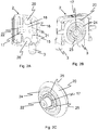
- FIG 2A a cross section through the housing 2 and an axis 17 of the roller 16 is shown.
- Figure 2B a cross-section through the housing 2 in a plane parallel to the roller 16 is shown, the axis 17 being shown cut flush with the outer contour of the roller 16.
- Figure 2C shows the roller 16 in a perspective view.
- the roller 16 can be seen to have an annular groove 18 into which a rubber-elastic O-ring 20 is pressed.
- the axle 17 has two stub axles, a front stub axle 21 and a rear stub axle 22, which are clicked into the front and rear bearing socket 15 and are rotatably fastened.
- the roller 16 has an outer ring 24 with four spokes 25 which are arranged at right angles to one another and which are fastened to the axle 17.
- the housing 2 is made in one piece from a suitable hard plastic material such as polyamide.
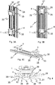
- FIG. 3A to 3C is a roller door lamella 27 with right ( Figures 3A and 3B ) a connecting piece 28 is shown, which is articulated to the roller door slat 27.
- the longitudinal edges 29 of the roller door lamella 27 are provided with a semicircular groove 30 into which a round rod-shaped longitudinal profile 31 of the connecting piece 28 has been pushed (see Fig. 4 ).
- the roller door lamella 27 is made of aluminum and has a fine, groove-shaped profile 33 and a V-shaped protuberance 34 so that a roller door with several coupled roller door lamellae 27 can be moved easily with the fingertips.
- the connectors 28 are made of a suitable hard plastic such as polyamide.
- transverse slots 35 with a saw blade or a milling cutter (not shown) are embedded. These transverse slots 35 serve to accommodate the fixing elements 4, see above that the roller door slats 27 coupled to the connecting pieces 28 cannot move in the longitudinal direction, ie are fixed.
- Figure 4 shows a plan view from below of the roller door lamella 27 with the connecting piece 28 and the guide part 1 latched into the roller door lamella 27.
- a cam 36 is provided on the inside of the roller door lamella 27 in the area of the semi-circular groove 30, behind which the resilient latching elements 12 are latched .
- the roller door lamella 27 has a longitudinal profile 38 on the inside on both sides of the protuberance 34, each of which corresponds to a longitudinal groove 39 on the rear wall 7 of the housing 2.
- the guide part 1 is thus fixed in a very stable manner on the roller door lamella 27.
- Figure 5A now shows a roller door segment 40 with several roller door slats 27, several connecting pieces 28 and several guide parts 1 in a perspective view bent outwards, ie with a convex radius or outer radius.
- the maximum angle between two roller door slats 27 is 40 °.
- Figure 5B shows the roller door segment 40 with several roller door slats 27, several connecting pieces 28 and several guide parts 1 in a perspective view bent inwards, ie with a concave radius or inner radius.
- the maximum angle between two roller door slats 27 is 30 °.
- FIG. 13 shows a bottom view of the roller door segment 40 in the configuration of FIG Figure 5B .
- guide element described above is also suitable for other purposes, for example to move individual lamellar panels made of a thin layer of wood or the like in front of a window.
Landscapes
- Engineering & Computer Science (AREA)
- Structural Engineering (AREA)
- Architecture (AREA)
- Civil Engineering (AREA)
- Support Devices For Sliding Doors (AREA)
Abstract
Description
- Die Erfindung betrifft ein Führungsteil für eine Rolltürlamellen aufweisende Rolltür eines Rolltürschranks nach dem Oberbegriff des Patentanspruchs 1.
- Rolltüren mit Lamellen für einen Wandschrank sind in verschiedenen Ausführungen bekannt. Beispielsweise ist aus
EP-A-0 461 220 ein Rolltürschrank mit einer Rolltür bekannt, welche an ringförmig geschlossenen, über Rollen geführten Bändern aufgehängt ist und aussenseitig um den Schrankkörper herumläuft. Dabei überdeckt die Rolltür den Schrankkörper quer zur ihrer Bewegungsrichtung vollständig, so dass der Sockel und der Deckel bei geschlossener Rolltür nicht sichtbar sind. Die Lamellen dieses bekannten Schranks sind über Gelenkverbindungen drehbar miteinander verbunden und zwei nebeneinanderliegende Lamellen haben im Querschnitt ein halbkreisförmiges, hohles Profil. Diese bekannten Schränke haben sich in der Praxis aus technischen und ästhetischen Gründen wohl bewährt, jedoch besitzen sie den Nachteil, dass das Öffnen und Schliessen der Rolltür ein lästiges Geräusch verursacht. Dies ist vor allem für Schlafzimmerschränke unerwünscht. - In
CH 700838 - Der vorliegenden Erfindung liegt nun die Aufgabe zugrunde, ein Führungsteil für eine Rolltür anzugeben, welches gut geführt ist, und welches die Lamellen einer Rolltür in gewünschter Position halten. Solche Führungsteile ermöglichen eine gute, leichtgängige und geräuscharme Führung einer Rolltür für einen Schrank mit einer fast beliebigen Form des Deckels und des Bodens.
- Diese Aufgabe wird durch ein Führungsteil für eine Rolltürlamellen aufweisende Rolltür eines Rolltürschranks gelöst, welches eine Rolle und einen Führungsstift aufweist, wobei ein Gehäuse und zwei in einer Führungsnut des Oberteils und/oder des Unterteils des Schranks führbare Führungsstifte am Gehäuse vorgesehen sind, und wobei das Gehäuse mindestens zwei federelastische Rastelemente, die hinter einen Nocken einer Rolltürlamelle einschnappbar sind, und zwei Fixierungselemente aufweist, die in einen Querschlitz der Rolltürlamelle fixierbar sind. Die Achse der Rolle ist im Wesentlichen senkrecht zu den zwei Führungsstiften angeordnet.
- Das erfindungsgemässe Führungsteil hat den grossen Vorteil, dass eine sichere Führung für die Rolltür in einer Nut im Boden und/oder im Deckel eines Schranks gegeben ist, wobei die Rolltür gleichzeitig von den Rollen der in regelmässigen Abständen an den Lamellen der Rolltür befestigten Führungsteile getragen wird. Die zwei Führungsstifte ermöglichen eine gute, leichtgängige und geräuscharme Führung einer Rolltür für einen Schrank mit einer fast beliebigen Form des Deckels und des Bodens.
- Das Gehäuse weist vorzugsweise eine Vorderwand, eine Rückwand, zwei Seitenwände, eine obere geschlossene Decke und eine untere freie Öffnung auf. Die zwei Führungsstifte sind vorzugsweise an der Vorderwand des Gehäuses vorstehend im Bereich der freien Öffnung angebracht. Unter Vorderwand wird die einer Rolltürlamelle abgewandten Seite des Gehäuses verstanden, wenn das Gehäuse an eine Rolltürlamelle angebracht ist. Unter Rückwand wird die einer Rolltürlamelle zugewandten Seite des Gehäuses verstanden, wenn der Träger an eine Rolltürlamelle angebracht ist.
- Die zwei Führungsstifte weisen eine kreiszylindrische Form auf und und stehen vor, so dass sie in einer Führungsnut eines Oberteils und/oder eines Unterteils eines Schrankes führbar sind. Bevorzugt sind die zwei Führungsstifte an der Vorderwand vorstehend an der linken Ecke und an der rechten Ecke angebracht.
- In einer bevorzugten Ausführungsform weist die Vorderwand und die Rückwand des Gehäuses je eine Lagerpfanne auf, in welche die Rolle mittels einer Achse einschnappbar und drehbar gelagert ist.
- Die zwei Fixierungselemente sind bevorzugt an den Seitenwänden des Gehäuses angeordnet.
- In einer bevorzugten Ausführungsform weist das Gehäuse vier federelastische Rastelemente auf.
- In einer besonderen Ausführungsform sind die zwei Fixierungselemente mittig an den Seitenwänden und bündig mit der Rückwand angeordnet.
- Die Rolle weist mit Vorteil eine ringförmige Nut und einen in der Nut angebrachten gummielastischen O-Ring auf.
- Vorzugsweise sind das Gehäuse und die Führungsstifte einstückig aus einem harten Kunststoff hergestellt. Geeignete harte Kunststoffe sind beispielsweise Polyamid. Die Achse der Rolle ist ebenfalls vorzugsweise aus einem harten Kunststoff hergestellt. Besonders bevorzugt ist die Achse der Rolle aus einem härteren Kunststoff als das Gehäuse mit der Lagerpfanne hergestellt, so dass eine besonders gute Gleiteigenschaft der Rolle entsteht.
- Des Weiteren umfasst die vorliegende Erfindung eine Rolltür mit mehreren Rolltürlamellen, die mittels Verbindungsstücke gelenkig miteinander verbunden sind. Dabei weisen die Verbindungsstücke einen Querschlitz auf, welcher mit einem Querschlitz der Rolltürlamelle übereinstimmt. Die Führungsteile fixieren die Rolltürlamellen und die Verbindungsstücke durch die in den Querschlitzen eingeführten Fixierungselemente der Führungsteile in Längsrichtung.
- Weitere Vorteile der Erfinderung ergeben sich aus der nachfolgenden Beschreibung eines Ausführungsbeispiels der Erfindung.
- Es zeigen:
- Fig. 1A
- ein Führungsteil in einer ersten perspektivischen Ansicht von oben,
- Fig. 1B
- das Führungsteil in einer perspektivischen Ansicht von unten mit Rolle,
- Fig. 1C
- das Führungsteil in einer perspektivischen Ansicht von der Rückseite,
- Fig. 1D
- das Führungsteil in einer perspektivischen Ansicht von unten ohne Rolle,
- Fig. 2A
- eine perspektivische Ansicht auf einen Querschnitt durch das Führungsteil längs der Achse der Rolle,
- Fig. 2B
- eine perspektivische Ansicht auf einen Querschnitt durch das Führungsteil senkrecht zur Achse der Rolle und versetzt zur Rolle,
- Fig. 2C
- die Rolle mit Achse in perspektivischer Ansicht,
- Fig. 3A
- eine Rolltürlamelle mit einem Verbindungsstück in perspektivischer Ansicht leicht von oben,
- Fig. 3B
- dieselbe Rolltürlamelle mit dem Verbindungsstück in perspektivischer Ansicht leicht von unten,
- Fig. 3C
- dieselbe Rolltürlamelle liegend in perspektivischer Ansicht ohne Verbindungsstück,
- Fig. 4
- eine Untenansicht auf das auf der Rolltürlamelle eingerastete Führungsteil,
- Fib. 5A
- ein Rolltürsegment mit mehreren Rolltürlamellen, mehreren Verbindungsstücken und mehreren Führungsteilen in einer perspektivischen Ansicht gebogen nach aussen,
- Fig. 5B
- das Rolltürsegment mit mehreren Rolltürlamellen, mehreren Verbindungsstücken und mehreren Führungsteilen in einer perspektivischen Ansicht gebogen nach innen, und
- Fig.6
- eine Untenansicht des Rolltürsegments der
Fig. 5B . - In den Figuren sind für dieselben Elemente jeweils dieselben Bezugszeichen verwendet worden und erstmalige Erklärungen betreffen alle Figuren, wenn nicht ausdrücklich anders erwähnt.
- Ein Ausführungsbeispiel der vorliegenden Erfindung wird anhand der beigefügten Zeichnungen näher erläutert.
- In den
Figuren 1A bis 1D ist ein Führungsteil 1 mit einem Gehäuse 2 und zwei Führungsstiften 3 dargestellt, die eine kreiszylindrische Form aufweisen. Ferner sind am Gehäuse 2 etwa auf halber Höhe der Rückwand 7 seitlich je ein Fixierungselement 4 angeordnet, welches im Wesentlichen die Form eines Dreiecks aufweist. Das Gehäuse 2 (sieheFigur 1A ) weist eine Vorderwand 6, eine Rückwand 7 und eine linke Seitenwand 8 und eine rechte Seitenwand 9 auf. Oben ist eine geschlossene Decke 10 und unten eine freie Öffnung 11 vorgesehen. Ferner sind oberhalb und unterhalb der Fixierungselemente 4 je ein federelastisches Rastelement 12 vorgesehen, welches hakenförmig ausgebildet ist. Die zwei Führungsstifte 3 sind an einer linken Ecke 13 zwischen der linken Seitenwand 8 und der Vorderwand 6 und an einer rechten Ecke 14 zwischen der rechten Seitenwand 9 und der Vorderwand 6 angebracht. Im Innern des Gehäuses 2 ist je eine Lagerpfanne 15 an der Vorderwand 6 und an der Rückwand 7 angeformt (sieheFigur 1D ). In diesen Lagerpfannen 15 wird die Achse 17 einer Rolle 16 gehalten (siehe unten). Die Achse 17 der Rolle 16 ist im Wesentlichen senkrecht zu den beiden Führungsstiften 3 angeordnet. - In
Figur 2A ist ein Querschnitt durch das Gehäuse 2 und eine Achse 17 der Rolle 16 gezeigt. InFigur 2B ist ein Querschnitt durch das Gehäuse 2 in einer Ebene parallel zur Rolle 16 gezeigt, wobei die Achse 17 bündig mit der Aussenkontur der Rolle 16 geschnitten dargestellt ist.Figur 2C zeigt die Rolle 16 in perspektivischer Darstellung. Wie inFigur 2A ersichtlich weist die Rolle 16 eine ringförmige Nut 18 auf, in welcher ein gummielastischer O-Ring 20 eingepresst ist. Die Achse 17 weist zwei Achsstümmel, einen vorderen Achsstümmel 21 und einen hinteren Achsstümmel 22, auf, welche in die vordere und hintere Lagerpfanne 15 eingeklickt und drehbar befestigt sind. Die Rolle 16 weist einen Aussenring 24 mit vier rechtwinklig zueinander angeordneten Speichen 25 auf, die mit der Achse 17 befestigt sind. - Das Gehäuse 2 ist einstückig aus einem geeigneten harten Kunststoffmaterial wie beispielsweise Polyamid hergestellt.
- In den
Figuren 3A bis 3C ist eine Rolltürlamelle 27 mit rechts (Fig. 3A und 3B ) ein Verbindungsstück 28 dargestellt, welches gelenkig mit der Rolltürlamelle 27 verbunden ist. Dazu sind Längskanten 29 der Rolltürlamelle 27 mit einer halbringförmigen Nut 30 versehen, in welche ein rundstabförmiges Längsprofil 31 des Verbindungsstücks 28 hineingeschoben worden ist (sieheFig. 4 ). Die Rolltürlamelle 27 ist aus Aluminium gefertigt und weist aussen ein feines rillenförmiges Profil 33 und einer v-förmigen Ausstülpung 34 auf, so dass man eine Rolltür mit mehreren gekoppelten Rolltürlamellen 27 einfach mit den Fingerkuppen bewegen kann. Die Verbindungsstücke 28 sind aus einem geeigneten harten Kunststoff wie Polyamid hergestellt. In den Rolltürlamellen 27 mit den gekoppelten Verbindungsstücken 28 sind Querschlitze 35 mit einem Sägeblatt oder einem Fräser (nicht dargestellt) eingelassen. Diese Querschlitze 35 dienen dazu, die Fixierungselemente 4 aufzunehmen, so dass die mit den Verbindungsstücken 28 gekoppelten Rolltürlamellen 27 sich in Längsrichtung nicht verschieben können, d.h. fixiert sind. -
Figur 4 zeigt in Draufsicht von unten die Rolltürlamelle 27 mit dem Verbindungsstück 28 und dem in der Rolltürlamelle 27 eingerasteten Führungsteil 1. Dazu sind an der Innenseite der Rolltürlamelle 27 im Bereich der halbringförmigen Nut 30 je ein Nocken 36 vorgesehen, hinter welchem die federelastischen Rastelemente 12 eingerastet sind. Ferner weist die Rolltürlamelle 27 an der Innenseite auf beiden Seiten der Ausstülpung 34 je ein Längsprofil 38 auf, welches mit je einer Längsnut 39 auf der Rückwand 7 des Gehäuses 2 übereinkommt. Damit ist das Führungsteil 1 sehr stabil auf der Rolltürlamelle 27 fixiert. -
Figur 5A zeigt nun ein Rolltürsegment 40 mit mehreren Rolltürlamellen 27, mehreren Verbindungsstücken 28 und mehreren Führungsteilen 1 in einer perspektivischen Ansicht gebogen nach aussen, d.h. bei einem konvexen Radius oder Aussenradius. Der maximale Winkel zwischen zwei Rolltürlamellen 27 beträgt dabei 40°. -
Figur 5B zeigt das Rolltürsegment 40 mit mehreren Rolltürlamellen 27, mehreren Verbindungsstücken 28 und mehreren Führungsteilen 1 in einer perspektivischen Ansicht gebogen nach innen, d.h. bei einem konkaven Radius oder Innenradius. Der maximale Winkel zwischen zwei Rolltürlamellen 27 beträgt dabei 30°. -
Figur 6 zeigt eine Untenansicht auf das Rolltürsegment 40 in der Konfiguration derFigur 5B . - Es versteht sich ferner für den Fachmann, dass das oben beschriebene Führungselement auch für andere Zwecke geeignet ist, beispielsweise um einzelne lamellenförmige Blenden aus einer dünnen Holzschicht oder dergleichen vor einem Fenster zu verschieben.
-
- 1
- Führungsteil
- 2
- Gehäuse
- 3
- Führungsstift
- 4
- Fixierungselement
- 5 6
- Vorderwand
- 7
- Rückwand
- 8
- linke Seitenwand
- 9
- rechte Seitenwand
- 10
- geschlossene Decke
- 11
- untere freie Öffnung
- 12
- federelastisches Rastelement
- 13
- linke Ecke
- 14
- rechte Ecke
- 15
- Lagerpfanne
- 16
- Rolle
- 17
- Achse
- 18
- ringförmige Nut
- 19 20
- gummielastischer O-Ring
- 21
- vorderer Achsstümmel
- 22
- hinterer Achsstümmel
- 23 24
- Aussenring
- 25
- Speiche
- 26 27
- Rolltürlamelle
- 28
- Verbindungsstück
- 29
- Längskante
- 30
- halbringförmige Nut
- 31
- rundstabförmiges Längsprofil
- 32
- federelastisches Rastelement
- 33
- feines rillenförmiges Profil
- 34
- v-förmige Ausstülpung
- 35
- Querschlitze
- 36
- Nocken
- 37 38
- Längsprofil
- 39
- Längsnut
- 40
- Rolltürsegment
Claims (10)
- Führungsteil (1) für eine Rolltürlamellen (27) aufweisende Rolltür eines Rolltürschranks, mit einer Rolle (16) und einem Führungsstift, dadurch gekennzeichnet, dass ein Gehäuse (2) und zwei in einer Führungsnut eines Oberteils und/oder eines Unterteils des Rolltürschranks führbare Führungsstifte (3) am Gehäuse (2) vorgesehen sind, wobei das Gehäuse (2) mindestens zwei federelastische Rastelemente (12), die hinter einen Nocken (36) einer Rolltürlamelle (27) der Rolltür einschnappbar sind, und zwei Fixierungselemente (4) aufweist, die in einen Querschlitz (35) der Rolltürlamelle (27) fixierbar sind, wobei die Achse (17) der Rolle (16) im Wesentlichen senkrecht zu den zwei Führungsstiften (3) angeordnet ist.
- Führungsteil (1) nach Anspruch 1, dadurch gekennzeichnet, dass das Gehäuse (2) eine Vorderwand (7), eine Rückwand (6), zwei Seitenwände (8, 9), eine obere geschlossene Decke (10) und eine untere freie Öffnung (11) aufweist.
- Führungsteil (1) nach Anspruch 1 oder 2, dadurch gekennzeichnet, dass die zwei Führungsstifte (3) an der Vorderwand (7) vorstehend an der linken Ecke (13) und an der rechten Ecke (14) angebracht sind.
- Führungsteil (1) nach einem der Ansprüche 1 bis 3, dadurch gekennzeichnet, dass die Vorderwand (7) und die Rückwand (6) des Gehäuses (2) je eine Lagerpfanne (15) aufweisen, in welche die Rolle (16) mittels der Achse (17) einschnappbar und drehbar gelagert ist.
- Führungsteil (1) nach einem der Ansprüche 1 bis 4, dadurch gekennzeichnet, dass die zwei Fixierungselemente (4) an den Seitenwänden (8, 9) des Gehäuses (2) angeordnet sind.
- Führungsteil (1) nach einem der Ansprüche 1 bis 5, dadurch gekennzeichnet, dass das Gehäuse (2) vier federelastischen Rastelemente (12) aufweist.
- Führungsteil (1) nach einem der Ansprüche 2 bis 6, dadurch gekennzeichnet, dass die zwei Fixierungselemente (4) mittig an den Seitenwänden (8, 9) und bündig mit der Rückwand (7) angeordnet sind.
- Führungsteil (1) nach einem der Ansprüche 1 bis 7, dadurch gekennzeichnet, dass die Rolle (16) eine ringförmige Nut (18) und einen in der Nut angebrachten gummielastischen O-Ring (20) aufweist.
- Führungsteil (1) nach einem der Ansprüche 1 bis 8, dadurch gekennzeichnet, dass das Gehäuse (2) und die Führungsstifte (3) einstückig aus einem harten Kunststoff, wie Polyamid, hergestellt sind.
- Rolltür mit mehreren Rolltürlamellen (27), die mittels Verbindungsstücke (28) gelenkig miteinander verbunden sind, dadurch gekennzeichnet, dass die Verbindungsstücke (28) einen Querschlitz (35) aufweisen, welcher mit dem Querschlitz (35) der Rolltürlamelle (27) übereinstimmt, und Führungsteile (1) nach einem der Ansprüche 1 bis 9 vorgesehen sind, welche die Rolltürlamellen (27) und die Verbindungsstücke (28) durch die in den Querschlitzen (35) eingeführten Fixierungselemente (4) der Führungsteile (1) in Längsrichtung fixieren.
Applications Claiming Priority (1)
| Application Number | Priority Date | Filing Date | Title |
|---|---|---|---|
| CH00972/19A CH716474A2 (de) | 2019-07-31 | 2019-07-31 | Führungsteil für eine Rolltür eines Rolltürschranks. |
Publications (3)
| Publication Number | Publication Date |
|---|---|
| EP3910151A1 true EP3910151A1 (de) | 2021-11-17 |
| EP3910151B1 EP3910151B1 (de) | 2024-10-02 |
| EP3910151C0 EP3910151C0 (de) | 2024-10-02 |
Family
ID=71783809
Family Applications (1)
| Application Number | Title | Priority Date | Filing Date |
|---|---|---|---|
| EP20186764.5A Active EP3910151B1 (de) | 2019-07-31 | 2020-07-20 | Führungsteil für eine rolltür |
Country Status (2)
| Country | Link |
|---|---|
| EP (1) | EP3910151B1 (de) |
| CH (1) | CH716474A2 (de) |
Cited By (2)
| Publication number | Priority date | Publication date | Assignee | Title |
|---|---|---|---|---|
| DE202022102918U1 (de) | 2022-05-25 | 2023-08-29 | Roto Frank Fenster- und Türtechnologie GmbH | Beschlageinheit mit einer Führungsrolle mit einem Reibmantel |
| DE102022205298A1 (de) | 2022-05-25 | 2023-11-30 | Roto Frank Fenster- und Türtechnologie GmbH | Führungsrolle mit zweifachem Reibmantel |
Citations (4)
| Publication number | Priority date | Publication date | Assignee | Title |
|---|---|---|---|---|
| CA690670A (en) * | 1964-07-14 | Schindlauer Karl | Roller equipment for sliding door | |
| US4279454A (en) * | 1978-09-08 | 1981-07-21 | Matsushita Electric Industrial Co., Ltd. | Cabinet with foldable sliding doors |
| EP0461220A1 (de) | 1990-01-03 | 1991-12-18 | Wogg Ag | Rolltürschrank. |
| CH700838A2 (de) | 2009-04-20 | 2010-10-29 | Willi Glaeser | Führungselement für eine Rolltür. |
-
2019
- 2019-07-31 CH CH00972/19A patent/CH716474A2/de unknown
-
2020
- 2020-07-20 EP EP20186764.5A patent/EP3910151B1/de active Active
Patent Citations (4)
| Publication number | Priority date | Publication date | Assignee | Title |
|---|---|---|---|---|
| CA690670A (en) * | 1964-07-14 | Schindlauer Karl | Roller equipment for sliding door | |
| US4279454A (en) * | 1978-09-08 | 1981-07-21 | Matsushita Electric Industrial Co., Ltd. | Cabinet with foldable sliding doors |
| EP0461220A1 (de) | 1990-01-03 | 1991-12-18 | Wogg Ag | Rolltürschrank. |
| CH700838A2 (de) | 2009-04-20 | 2010-10-29 | Willi Glaeser | Führungselement für eine Rolltür. |
Cited By (2)
| Publication number | Priority date | Publication date | Assignee | Title |
|---|---|---|---|---|
| DE202022102918U1 (de) | 2022-05-25 | 2023-08-29 | Roto Frank Fenster- und Türtechnologie GmbH | Beschlageinheit mit einer Führungsrolle mit einem Reibmantel |
| DE102022205298A1 (de) | 2022-05-25 | 2023-11-30 | Roto Frank Fenster- und Türtechnologie GmbH | Führungsrolle mit zweifachem Reibmantel |
Also Published As
| Publication number | Publication date |
|---|---|
| CH716474A2 (de) | 2021-02-15 |
| EP3910151B1 (de) | 2024-10-02 |
| EP3910151C0 (de) | 2024-10-02 |
Similar Documents
| Publication | Publication Date | Title |
|---|---|---|
| DE112014004253T5 (de) | Insektenschiebefenstergitterinstallationsstruktur umfassend einen Schienenrahmen mit einer entfernbaren Segmentstruktur | |
| DE2317086B2 (de) | Tür o.dgl. aus mehreren teleskopartig verschiebbaren Elementen | |
| DE102011011113B4 (de) | Rahmensystem eines Partikelschutzgitters | |
| EP3427984B2 (de) | Schutzvorrichtung für einen fahrzeuginnenraum | |
| EP2642194B1 (de) | Leuchte zur Montage an einem Decken- oder Wandelement, sowie System mit einer solchen Leuchte, montiert an dem Decken- oder Wandelement | |
| EP3910151B1 (de) | Führungsteil für eine rolltür | |
| DE8211487U1 (de) | Ventil | |
| DE4414812C1 (de) | Scharnier zur gelenkigen, aushängbaren Verbindung zweier benachbarter Flügelfelder eines Sektional-Tores | |
| DE102013003519B4 (de) | Duschabtrennung | |
| DE102007023007B3 (de) | Lamellendach | |
| AT15184U1 (de) | Lichtbandsystem mit länglicher Tragschiene | |
| DE2715909A1 (de) | Rolladen-fensterelement | |
| DE3118559C2 (de) | Fensterseitenwand für Personenbeförderungsfahrzeuge | |
| DE202005012809U1 (de) | Schrankmöbel | |
| DE20009630U1 (de) | Rolladen mit einer ausziehbaren Lichtwand | |
| EP1748143A2 (de) | Vorrichtung zum Verschliessen von Gebäudeöffnungen | |
| DE202018100888U1 (de) | Rahmensystem für einen Insekten- oder Pollenschutz einer Gebäudeöffnung | |
| EP1688666B1 (de) | Profil für eine Verkleidung sowie Verkleidung | |
| DE2914474C2 (de) | ||
| DE4321466A1 (de) | Zarge für ein Fenster | |
| AT517263A1 (de) | Schließvorrichtung für eine Schiebetür | |
| DE102007023008B3 (de) | Lamellendach | |
| WO2005090734A1 (de) | Vorrichtung zum verschluss und/oder zum schutz von bauwerksöffnungen | |
| EP1681400B1 (de) | Dachfenster, insbesondere Wohndachfenster, mit Rolladen | |
| EP2754844A2 (de) | Lamellensystem |
Legal Events
| Date | Code | Title | Description |
|---|---|---|---|
| STAA | Information on the status of an ep patent application or granted ep patent |
Free format text: STATUS: UNKNOWN |
|
| PUAI | Public reference made under article 153(3) epc to a published international application that has entered the european phase |
Free format text: ORIGINAL CODE: 0009012 |
|
| STAA | Information on the status of an ep patent application or granted ep patent |
Free format text: STATUS: THE APPLICATION HAS BEEN PUBLISHED |
|
| AK | Designated contracting states |
Kind code of ref document: A1 Designated state(s): AL AT BE BG CH CY CZ DE DK EE ES FI FR GB GR HR HU IE IS IT LI LT LU LV MC MK MT NL NO PL PT RO RS SE SI SK SM TR |
|
| B565 | Issuance of search results under rule 164(2) epc |
Effective date: 20211015 |
|
| STAA | Information on the status of an ep patent application or granted ep patent |
Free format text: STATUS: REQUEST FOR EXAMINATION WAS MADE |
|
| 17P | Request for examination filed |
Effective date: 20220427 |
|
| RBV | Designated contracting states (corrected) |
Designated state(s): AL AT BE BG CH CY CZ DE DK EE ES FI FR GB GR HR HU IE IS IT LI LT LU LV MC MK MT NL NO PL PT RO RS SE SI SK SM TR |
|
| RAP1 | Party data changed (applicant data changed or rights of an application transferred) |
Owner name: WOGG FURNITURE AG |
|
| STAA | Information on the status of an ep patent application or granted ep patent |
Free format text: STATUS: EXAMINATION IS IN PROGRESS |
|
| 17Q | First examination report despatched |
Effective date: 20230706 |
|
| RAP1 | Party data changed (applicant data changed or rights of an application transferred) |
Owner name: WOGG AG |
|
| GRAP | Despatch of communication of intention to grant a patent |
Free format text: ORIGINAL CODE: EPIDOSNIGR1 |
|
| STAA | Information on the status of an ep patent application or granted ep patent |
Free format text: STATUS: GRANT OF PATENT IS INTENDED |
|
| INTG | Intention to grant announced |
Effective date: 20240506 |
|
| GRAS | Grant fee paid |
Free format text: ORIGINAL CODE: EPIDOSNIGR3 |
|
| GRAA | (expected) grant |
Free format text: ORIGINAL CODE: 0009210 |
|
| STAA | Information on the status of an ep patent application or granted ep patent |
Free format text: STATUS: THE PATENT HAS BEEN GRANTED |
|
| AK | Designated contracting states |
Kind code of ref document: B1 Designated state(s): AL AT BE BG CH CY CZ DE DK EE ES FI FR GB GR HR HU IE IS IT LI LT LU LV MC MK MT NL NO PL PT RO RS SE SI SK SM TR |
|
| REG | Reference to a national code |
Ref country code: GB Ref legal event code: FG4D Free format text: NOT ENGLISH |
|
| REG | Reference to a national code |
Ref country code: CH Ref legal event code: EP |
|
| REG | Reference to a national code |
Ref country code: IE Ref legal event code: FG4D Free format text: LANGUAGE OF EP DOCUMENT: GERMAN |
|
| REG | Reference to a national code |
Ref country code: DE Ref legal event code: R096 Ref document number: 502020009358 Country of ref document: DE |
|
| U01 | Request for unitary effect filed |
Effective date: 20241007 |
|
| U07 | Unitary effect registered |
Designated state(s): AT BE BG DE DK EE FI FR IT LT LU LV MT NL PT RO SE SI Effective date: 20241028 |
|
| PG25 | Lapsed in a contracting state [announced via postgrant information from national office to epo] |
Ref country code: IS Free format text: LAPSE BECAUSE OF FAILURE TO SUBMIT A TRANSLATION OF THE DESCRIPTION OR TO PAY THE FEE WITHIN THE PRESCRIBED TIME-LIMIT Effective date: 20250202 Ref country code: HR Free format text: LAPSE BECAUSE OF FAILURE TO SUBMIT A TRANSLATION OF THE DESCRIPTION OR TO PAY THE FEE WITHIN THE PRESCRIBED TIME-LIMIT Effective date: 20241002 |
|
| PG25 | Lapsed in a contracting state [announced via postgrant information from national office to epo] |
Ref country code: ES Free format text: LAPSE BECAUSE OF FAILURE TO SUBMIT A TRANSLATION OF THE DESCRIPTION OR TO PAY THE FEE WITHIN THE PRESCRIBED TIME-LIMIT Effective date: 20241002 |
|
| PG25 | Lapsed in a contracting state [announced via postgrant information from national office to epo] |
Ref country code: NO Free format text: LAPSE BECAUSE OF FAILURE TO SUBMIT A TRANSLATION OF THE DESCRIPTION OR TO PAY THE FEE WITHIN THE PRESCRIBED TIME-LIMIT Effective date: 20250102 |
|
| PG25 | Lapsed in a contracting state [announced via postgrant information from national office to epo] |
Ref country code: GR Free format text: LAPSE BECAUSE OF FAILURE TO SUBMIT A TRANSLATION OF THE DESCRIPTION OR TO PAY THE FEE WITHIN THE PRESCRIBED TIME-LIMIT Effective date: 20250103 |
|
| PG25 | Lapsed in a contracting state [announced via postgrant information from national office to epo] |
Ref country code: PL Free format text: LAPSE BECAUSE OF FAILURE TO SUBMIT A TRANSLATION OF THE DESCRIPTION OR TO PAY THE FEE WITHIN THE PRESCRIBED TIME-LIMIT Effective date: 20241002 Ref country code: CZ Free format text: LAPSE BECAUSE OF FAILURE TO SUBMIT A TRANSLATION OF THE DESCRIPTION OR TO PAY THE FEE WITHIN THE PRESCRIBED TIME-LIMIT Effective date: 20241002 |
|
| PG25 | Lapsed in a contracting state [announced via postgrant information from national office to epo] |
Ref country code: RS Free format text: LAPSE BECAUSE OF FAILURE TO SUBMIT A TRANSLATION OF THE DESCRIPTION OR TO PAY THE FEE WITHIN THE PRESCRIBED TIME-LIMIT Effective date: 20250102 |
|
| PG25 | Lapsed in a contracting state [announced via postgrant information from national office to epo] |
Ref country code: SM Free format text: LAPSE BECAUSE OF FAILURE TO SUBMIT A TRANSLATION OF THE DESCRIPTION OR TO PAY THE FEE WITHIN THE PRESCRIBED TIME-LIMIT Effective date: 20241002 |
|
| PG25 | Lapsed in a contracting state [announced via postgrant information from national office to epo] |
Ref country code: SK Free format text: LAPSE BECAUSE OF FAILURE TO SUBMIT A TRANSLATION OF THE DESCRIPTION OR TO PAY THE FEE WITHIN THE PRESCRIBED TIME-LIMIT Effective date: 20241002 |
|
| PLBE | No opposition filed within time limit |
Free format text: ORIGINAL CODE: 0009261 |
|
| STAA | Information on the status of an ep patent application or granted ep patent |
Free format text: STATUS: NO OPPOSITION FILED WITHIN TIME LIMIT |
|
| U20 | Renewal fee for the european patent with unitary effect paid |
Year of fee payment: 6 Effective date: 20250710 |
|
| 26N | No opposition filed |
Effective date: 20250703 |
|
| PGFP | Annual fee paid to national office [announced via postgrant information from national office to epo] |
Ref country code: GB Payment date: 20250724 Year of fee payment: 6 |
|
| PGFP | Annual fee paid to national office [announced via postgrant information from national office to epo] |
Ref country code: CH Payment date: 20250801 Year of fee payment: 6 |
|
| PG25 | Lapsed in a contracting state [announced via postgrant information from national office to epo] |
Ref country code: IE Free format text: LAPSE BECAUSE OF NON-PAYMENT OF DUE FEES Effective date: 20250720 |
|
| PG25 | Lapsed in a contracting state [announced via postgrant information from national office to epo] |
Ref country code: MC Free format text: LAPSE BECAUSE OF FAILURE TO SUBMIT A TRANSLATION OF THE DESCRIPTION OR TO PAY THE FEE WITHIN THE PRESCRIBED TIME-LIMIT Effective date: 20241002 |
|
| REG | Reference to a national code |
Ref country code: CH Ref legal event code: U11 Free format text: ST27 STATUS EVENT CODE: U-0-0-U10-U11 (AS PROVIDED BY THE NATIONAL OFFICE) Effective date: 20260801 |
|
| PG25 | Lapsed in a contracting state [announced via postgrant information from national office to epo] |
Ref country code: CY Free format text: LAPSE BECAUSE OF FAILURE TO SUBMIT A TRANSLATION OF THE DESCRIPTION OR TO PAY THE FEE WITHIN THE PRESCRIBED TIME-LIMIT Effective date: 20241002 |