EP3909098B1 - Steckverbinderteil mit einem mit einem gehäuseteil zu verbindenden verbinderteil - Google Patents
Steckverbinderteil mit einem mit einem gehäuseteil zu verbindenden verbinderteil Download PDFInfo
- Publication number
- EP3909098B1 EP3909098B1 EP19818099.4A EP19818099A EP3909098B1 EP 3909098 B1 EP3909098 B1 EP 3909098B1 EP 19818099 A EP19818099 A EP 19818099A EP 3909098 B1 EP3909098 B1 EP 3909098B1
- Authority
- EP
- European Patent Office
- Prior art keywords
- connector part
- latching
- connector
- plug
- housing
- Prior art date
- Legal status (The legal status is an assumption and is not a legal conclusion. Google has not performed a legal analysis and makes no representation as to the accuracy of the status listed.)
- Active
Links
Images




Classifications
-
- H—ELECTRICITY
- H01—ELECTRIC ELEMENTS
- H01R—ELECTRICALLY-CONDUCTIVE CONNECTIONS; STRUCTURAL ASSOCIATIONS OF A PLURALITY OF MUTUALLY-INSULATED ELECTRICAL CONNECTING ELEMENTS; COUPLING DEVICES; CURRENT COLLECTORS
- H01R13/00—Details of coupling devices of the kinds covered by groups H01R12/70 or H01R24/00 - H01R33/00
- H01R13/46—Bases; Cases
- H01R13/502—Bases; Cases composed of different pieces
- H01R13/506—Bases; Cases composed of different pieces assembled by snap action of the parts
-
- H—ELECTRICITY
- H01—ELECTRIC ELEMENTS
- H01R—ELECTRICALLY-CONDUCTIVE CONNECTIONS; STRUCTURAL ASSOCIATIONS OF A PLURALITY OF MUTUALLY-INSULATED ELECTRICAL CONNECTING ELEMENTS; COUPLING DEVICES; CURRENT COLLECTORS
- H01R13/00—Details of coupling devices of the kinds covered by groups H01R12/70 or H01R24/00 - H01R33/00
- H01R13/46—Bases; Cases
- H01R13/516—Means for holding or embracing insulating body, e.g. casing, hoods
-
- B—PERFORMING OPERATIONS; TRANSPORTING
- B60—VEHICLES IN GENERAL
- B60L—PROPULSION OF ELECTRICALLY-PROPELLED VEHICLES; SUPPLYING ELECTRIC POWER FOR AUXILIARY EQUIPMENT OF ELECTRICALLY-PROPELLED VEHICLES; ELECTRODYNAMIC BRAKE SYSTEMS FOR VEHICLES IN GENERAL; MAGNETIC SUSPENSION OR LEVITATION FOR VEHICLES; MONITORING OPERATING VARIABLES OF ELECTRICALLY-PROPELLED VEHICLES; ELECTRIC SAFETY DEVICES FOR ELECTRICALLY-PROPELLED VEHICLES
- B60L53/00—Methods of charging batteries, specially adapted for electric vehicles; Charging stations or on-board charging equipment therefor; Exchange of energy storage elements in electric vehicles
- B60L53/10—Methods of charging batteries, specially adapted for electric vehicles; Charging stations or on-board charging equipment therefor; Exchange of energy storage elements in electric vehicles characterised by the energy transfer between the charging station and the vehicle
- B60L53/14—Conductive energy transfer
- B60L53/16—Connectors, e.g. plugs or sockets, specially adapted for charging electric vehicles
-
- H—ELECTRICITY
- H01—ELECTRIC ELEMENTS
- H01R—ELECTRICALLY-CONDUCTIVE CONNECTIONS; STRUCTURAL ASSOCIATIONS OF A PLURALITY OF MUTUALLY-INSULATED ELECTRICAL CONNECTING ELEMENTS; COUPLING DEVICES; CURRENT COLLECTORS
- H01R2201/00—Connectors or connections adapted for particular applications
- H01R2201/26—Connectors or connections adapted for particular applications for vehicles
-
- Y—GENERAL TAGGING OF NEW TECHNOLOGICAL DEVELOPMENTS; GENERAL TAGGING OF CROSS-SECTIONAL TECHNOLOGIES SPANNING OVER SEVERAL SECTIONS OF THE IPC; TECHNICAL SUBJECTS COVERED BY FORMER USPC CROSS-REFERENCE ART COLLECTIONS [XRACs] AND DIGESTS
- Y02—TECHNOLOGIES OR APPLICATIONS FOR MITIGATION OR ADAPTATION AGAINST CLIMATE CHANGE
- Y02T—CLIMATE CHANGE MITIGATION TECHNOLOGIES RELATED TO TRANSPORTATION
- Y02T10/00—Road transport of goods or passengers
- Y02T10/60—Other road transportation technologies with climate change mitigation effect
- Y02T10/70—Energy storage systems for electromobility, e.g. batteries
-
- Y—GENERAL TAGGING OF NEW TECHNOLOGICAL DEVELOPMENTS; GENERAL TAGGING OF CROSS-SECTIONAL TECHNOLOGIES SPANNING OVER SEVERAL SECTIONS OF THE IPC; TECHNICAL SUBJECTS COVERED BY FORMER USPC CROSS-REFERENCE ART COLLECTIONS [XRACs] AND DIGESTS
- Y02—TECHNOLOGIES OR APPLICATIONS FOR MITIGATION OR ADAPTATION AGAINST CLIMATE CHANGE
- Y02T—CLIMATE CHANGE MITIGATION TECHNOLOGIES RELATED TO TRANSPORTATION
- Y02T10/00—Road transport of goods or passengers
- Y02T10/60—Other road transportation technologies with climate change mitigation effect
- Y02T10/7072—Electromobility specific charging systems or methods for batteries, ultracapacitors, supercapacitors or double-layer capacitors
-
- Y—GENERAL TAGGING OF NEW TECHNOLOGICAL DEVELOPMENTS; GENERAL TAGGING OF CROSS-SECTIONAL TECHNOLOGIES SPANNING OVER SEVERAL SECTIONS OF THE IPC; TECHNICAL SUBJECTS COVERED BY FORMER USPC CROSS-REFERENCE ART COLLECTIONS [XRACs] AND DIGESTS
- Y02—TECHNOLOGIES OR APPLICATIONS FOR MITIGATION OR ADAPTATION AGAINST CLIMATE CHANGE
- Y02T—CLIMATE CHANGE MITIGATION TECHNOLOGIES RELATED TO TRANSPORTATION
- Y02T90/00—Enabling technologies or technologies with a potential or indirect contribution to GHG emissions mitigation
- Y02T90/10—Technologies relating to charging of electric vehicles
- Y02T90/14—Plug-in electric vehicles
Definitions
- the invention relates to a connector part for connection to a mating connector part according to the preamble of claim 1 and a method for assembling a connector part.
- Such a connector part comprises a housing part and a connector part to be latched to the housing part, which connector part has a plug-in section on which at least one (electrical) contact element is arranged for the plug-in connection with the mating connector part.
- a cover element is to be connected to the connector part and has at least one line outlet for accommodating an electrical line connected to the connector part.
- a connector part can be used, for example, as a charging socket for charging an electrically driven vehicle (also referred to as an electric vehicle).
- an electrically driven vehicle also referred to as an electric vehicle.
- Such a charging socket is arranged on a vehicle, for example, and can be plugged into an associated mating connector part in the form of a charging plug on a cable connected to a charging station, in order in this way to establish an electrical connection between the charging station and the vehicle.
- a housing part which is visible from the outside to be configured differently for different vehicles according to the wishes of a vehicle manufacturer.
- a connector part that forms the plug-in section with electrical contact elements arranged thereon is usually standardized with regard to its plug-in face. Because housing parts are designed differently for different vehicles, it is difficult with previous approaches to use identical parts for the formation of the connector part, because conventionally the connector part for attachment to the housing part (which varies depending on the vehicle) also has to be adapted.
- a cover element - which can be designed, for example, as a grommet and is used, in particular, to seal the connector part on the rear side where an electrical line is routed to the connector part - by means of a clamp to be screwed and thus clamped to the connector part connect. This further complicates the assembly process of the connector part.
- a tongue and groove connection is provided for arranging the charging socket on a holding device.
- a charging socket can be connected to a charging socket holder, for example via a fastening flange and screw connections.
- a connector part which has a housing with an insertion opening formed therein for the insertion of a mating connector part and a base part which can be connected to the housing part.
- the base part can be connected to the housing part via a connection in the manner of a bayonet catch, the connection being able to be fixed via a locking frame.
- the invention is based on the object of providing a connector part and a method for assembling a connector part which enable simple assembly while fastening a cover element to the connector part.
- the connector part has a frame part, which is to be connected to the connector part in a latching manner and is designed to fix the cover element to the connector part in a position in which it is attached to the connector part.
- the connector part is thus designed in several parts with components to be connected in a modular manner.
- the connector part which forms a plug face via the plug-in section formed on it and the electrical contact elements arranged thereon, can be connected in a latching manner to the housing part, which has a so-called variance range for arranging the Connector part forms, for example, on a vehicle.
- the connector part can be designed as an identical part for use on different connector parts and its mating face is standardized according to a standard for a charging system, for example, the housing part is designed variably and depends on, for example, a vehicle type on which the connector part is used as a charging socket, for example should come.
- the modular design of the connector part in interaction with the housing part which can be varied according to customer requirements, thus enables the use of identical parts for the connector part.
- the frame part is also of modular design and can be connected to the connector part in a latching manner.
- the frame part is used here to fix a cover element, which is used for sealing on the connector part in an area in which one or more electrical lines are arranged on the connector part, to the connector part.
- the cover element is fixed to the connector part by simply latching the frame part to the connector part, without having to take any further measures, in particular to produce a screw connection or the like. The assembly and arrangement of the cover element can thus be carried out easily and conveniently.
- both the housing part can be locked to the connector part and the frame part to the connector part, screw connections for connecting the individual parts to one another can be dispensed with, which can make assembly of the connector part easy overall.
- the cover element is designed, for example, as a grommet made of a soft material, for example a rubber material, and in this case is preferably flexibly deformable.
- the cover element can, for example, have the form of a rigid cover, on the edge of which facing the connector part, for example, a seal can be attached or molded (by means of injection molding).
- the cover element is attached to the connector part, for example with an edge section, and is held on the connector part via the frame part when the frame part is attached to the connector part. With its edge section, the cover element can be in contact with the connector part in such a way that a transition between the connector part and the cover element is sealed in a moisture-tight manner and moisture cannot get into an area in which one or more electrical lines are arranged on the connector part.
- the one or the several In this case, electrical lines are led out of the cover element via one or more line outlets, with a transition between the cover element and the electrical lines advantageously being sealed in a moisture-tight manner.
- the housing part has at least one first latching element and the connector part has at least one first counter-latching element.
- the at least one first latching element and the at least one first counter-latching element can be brought into engagement with one another to connect the connector part to the housing part along a (first) assembly direction, so that the connector part and the housing part have a positive fit via the at least one first latching element and the at least one first counter-latching element be locked together.
- the at least one first latching element and/or the at least one first counter-latching element can be elastically deflected at least over a certain deflection path, so that when the housing part and the connector part are placed on one another, the at least one first latching element and/or the at least one first counter-latching element can be elastically deflected and the at least one first latching element and the at least one first counter-latching element can thus snap into engagement with one another in a form-fitting manner.
- the at least one first counter-locking element can be designed as a rigid locking projection on the connector part.
- the at least one first counter-locking element has, for example, a ramp that allows the at least one first locking element of the housing part to run onto the at least one first counter-locking element when the housing part and the connector part are attached to one another along the (first) assembly direction, in order to Establish positive locking between the housing part and the connector part.
- the housing part has a housing body, the at least one first latching element being designed as a latching finger extending from the housing body along the (first) assembly direction.
- One or more first latching elements thus protrude as latching fingers from the housing body of the housing part and can be elastically deflected, preferably transversely to the (first) assembly direction, so that when the housing part and the connector part are attached to one another, a positive latching connection can be established between the connector part and the housing part.
- the frame part also serves to fix the cover element to the connector part, the locking to secure the connection between the connector part and the housing part by the frame part acting on the at least one first latching element of the housing part in the position attached to the connector part and locking this in its connection with the associated at least one first counter-latching element of the connector part. If the frame part is attached to the connector part, a connection between the connector part and the housing part cannot be released easily, at least not without removing the frame part and then releasing the latching connection between the housing part and the connector part.
- the frame part can act, for example, on an engagement element formed on the at least one first latching element in the manner of a tab, in order to lock the at least one first latching element in its latched position with the at least one first counter-latching element.
- the frame part can, for example, encompass the engagement element and thus hold the engagement element in position, so that deflection of the at least one first latching element is prevented.
- the frame part has at least one second latching element and the connector part has at least one second counter-latching element.
- the at least one second latching element of the frame part and the at least one second counter-latching element of the connector part can be brought into latching engagement with one another in order to connect the frame part to the connector part along a (second) assembly direction, in order in this way to create a form fit between the frame part and the connector part.
- the frame part can thus also be connected to the connector part in a latching manner, in which latching elements are brought into latching engagement with associated counter-latching elements.
- Mounting is generally along an axis, with the first mounting direction and the second mounting direction being aligned along the axis.
- the second mounting direction can be opposite to the first mounting direction, but can also be in the same direction as the first mounting direction.
- the at least one second latching element of the frame part and/or the at least one counter-latching element of the connector part can be elastic by a certain adjustment path be deflectable in order to allow a latching connection when the frame part and the connector part are attached to one another.
- the at least one second latching element of the frame part can be designed to be elastically resilient, while the at least one second counter-latching element of the connector part is designed as a rigid latching projection.
- the at least one second counter-locking element has, for example, a ramp that allows the at least one second locking element to run onto the counter-locking element to produce a positive connection when the frame part and the connector part are attached to one another.
- the frame part has a frame body.
- the at least one second latching element of the frame part is designed, for example, as a latching finger, which extends from the frame body along the (second) assembly direction and thus protrudes from the frame body.
- the at least one second latching element is preferably designed to be elastically resilient and can be elastically deflected when the frame part and the connector part are attached to one another in order to be pushed aside when attached and to produce a snapping, form-fitting connection with the connector part.
- the housing part is designed to act on the at least one second latching element of the frame part in order to to lock the latching connection between the connector part and the frame part against loosening.
- the connection between the frame part and the connector part is secured via the housing part, in that the housing part acts on the at least one second latching element and holds it in its positive engagement with the associated at least one second counter-latching element of the connector part.
- the housing part can encompass the at least one second latching element, for example, in such a way that deflection of the at least one second latching element for releasing the form-fitting connection is prevented.
- the housing part has a plurality of first latching elements and the frame part has a plurality of second latching elements, which can each be designed as latching fingers and thus protrude from the housing body of the housing part on the one hand and from the frame body of the frame part on the other.
- a first latching element of the housing part can be accommodated between two second latching elements of the frame part and/or a second latching element of the frame part between two first latching elements of the housing part.
- the first latching elements and the second latching elements can each be distributed circumferentially around the axis of the assembly direction on the housing body on the one hand and the frame body on the other hand, forming a comb structure, with the latching elements engaging in one another in the assembled position of the connector part in such a way that between two second latching elements in each case a first locking element and between two first locking elements in each case a second locking element comes to rest.
- the connector part has a housing part on which a plurality of first counter-locking elements for locking connection with the first locking elements of the housing part and a plurality of second counter-locking elements for locking connection with the second locking elements of the frame part are arranged.
- the first counter-locking elements and the second counter-locking elements can be arranged in alternation with one another, viewed along a circumferential direction around the axis of the assembly direction.
- the first counter-locking elements and the second counter-locking elements are thus arranged on the housing of the connector part in such a way that a first counter-locking element is followed by a second counter-locking element and then again by a first counter-locking element.
- the connector part has a sealing element, which is arranged, for example, between the connector part and the housing part and acts between the connector part and the housing part (when the connector part and the housing part are attached to one another) in order to make a transition between the connector part and the housing part moisture-tight to seal.
- a sealing element which is arranged, for example, between the connector part and the housing part and acts between the connector part and the housing part (when the connector part and the housing part are attached to one another) in order to make a transition between the connector part and the housing part moisture-tight to seal.
- the cover element comes to lie with an edge section between the frame part and the connector part and is made of a flexible, elastic material, for example a rubber material, there is also a transition between the cover element and the connector part sealed moisture-tight, with an elastic bias between the frame part and the connector part can be effected via the edge portion, which the second locking elements of the frame part and the second counter-locking elements of the Connector part holds backlash engaged with each other.
- the connection between the frame part and the connector part is thus made free of play.
- the object is also achieved by a method for assembling a connector part for connection to a mating connector part, in which a connector part, which has a plug-in section on which at least one contact element for plugging connection to the mating connector part is arranged, latches with a housing part and a cover element, which has at least one line outlet for receiving an electrical line connected to the connector part, is connected to the connector part. It is provided that a frame part is connected to the connector part in a latching manner, with the frame part fixing the cover element to the connector part in a position in which it is attached to the connector part.
- first the connector part latches with the housing part and then the frame part is connected to the connector part.
- first the frame part is connected to the connector part and then the connector part is latched to the housing part.
- the charging station 1 shows a charging station 1, which is used to charge an electrically driven vehicle 4, also referred to as an electric vehicle.
- the charging station 1 is designed to provide a charging current in the form of an alternating current or a direct current and has a cable 2 which is connected to the charging station 1 at one end 201 and to a mating connector part 3 in the form of a charging plug at the other end 200 connected is.
- the mating connector part 3 can be brought into engagement with an associated connector part 5 in the form of a charging socket on the vehicle 4 in a plugging manner.
- the charging station 1 can be electrically connected to the vehicle 4 in order to transmit charging currents from the charging station 1 to the vehicle 4 .
- FIG. 2 An exemplary embodiment of a connector part 5 in the form of a charging socket to be arranged, for example, on a vehicle 4 is shown 2 .
- the connector part 5 in the form of the charging socket has a housing part 50 which is to be fastened to an associated vehicle via fastening points 506 and on which a connector part 51 is arranged to form a plug face.
- the connector part 51 forms plug-in sections 510, 511, which extend along a plug-in direction E (see 1 ) can be plugged with an associated mating connector part 3 to electrical contacts 512, 513 on the plug portions 510, 511 electrically connected to the To contact mating connector part 3 and to establish an electrical connection between the charging station 1 and the vehicle 4.
- electrical contact elements 512 are arranged on an upper, first plug-in section 510, which can be used in particular to transmit a charging current in the form of an alternating current (possibly multi-phase).
- contact elements 513 are arranged on a lower, second plug-in section 511 , via which a charging current in the form of a direct current can be transmitted to the vehicle 4 .
- signal contacts for transmitting control signals can be provided on the plug-in sections 510, 511.
- the housing part 50 is usually variable in shape for different vehicles.
- the plug-in face provided by the connector part 51 is standardized, so that the plug-in connector part 5 can be brought into engagement with a correspondingly standardized, complementary charging plug 3 for charging the vehicle 4 .
- the connector part 51 In order to assemble the connector part 5, the connector part 51 must be attached to the housing part 50, it being desirable to use a predefined interface for connection, so that the connector part 51 can be used with a common part that can be connected to differently shaped housing parts 50 . This makes it possible to use a uniform connector part 51 on very different housing parts 50, which reduces the variety of parts and also reduces the effort and costs involved in designing a connector part 5 because adjustments to the connector part 51 are no longer necessary.
- FIG. 5 An embodiment of a connector part 5 show Figures 3 to 9A , 9B .
- the connector part 5 has a housing part 50 which is to be connected in a latching manner to a connector part 51 in such a way that plug-in sections 510, 511 of the connector part 51 come to rest in associated receiving openings 500, 501 on the front side 508 of the housing part 50 and thus on the front side 508 form a mating face for mating connection with an associated mating connector part 3 .
- a cover element 53 is arranged on the connector part 51 , which cover element serves to enclose electrical lines 54 on the connector part 51 in a moisture-tight manner and is held on the connector part 51 via a frame part 52 for this purpose.
- the cover element 53 has a sleeve body 530 made of an elastically deformable material, on which the line outlets 531 for receiving electrical lines 54 are formed, so that the electrical lines 54 are inserted into the cover element 53 and enclosed on the connector part 51 in a moisture-tight manner, such as this in particular 3 is evident.
- the housing part 50, the connector part 51 and the frame part 52 are connected to one another in a latching manner by the housing part 50, the connector part 51 and the frame part 52 being attached to one another.
- the frame part 52 encompasses an edge section 532 of the cover element 53 with a frame body 520 (see FIG 6 in synopsis with Figure 8B and 9B ), so that the cover element 53 is fixed to the connector part 51 via the frame part 52 .
- housing part 50 is first connected to the connector part 51 in a latching manner, as is shown in Figures 4 and 5 is shown.
- Housing part 50 has a housing body 502, from which latching elements 503 in the manner of latching fingers extend axially along a first assembly direction M1 to fix the connector part 51 to each other.
- a plurality of first latching elements 503 are distributed circumferentially around the first assembly direction M1 on the housing body 502, with each latching element 503 having a latching head 504 for latching with a respectively assigned counter-latching element 515 and an engagement element 505 protruding from the latching head 504.
- housing part 50 To connect housing part 50 to connector part 51, housing part 50 is placed on connector part 51 in assembly direction M1, so that latching elements 503 of housing part 50 with their latching heads 504 run onto ramps 516 on counter-latching elements 515 of connector part 51 and thus latch with the Counter-locking elements 515 engage, as in the transition from 4 towards figure 5 is evident.
- the cover element 53 is attached to a housing part 50 facing away Attached side of the connector part 51, like this 6 can be seen, and the frame part 52 is arranged on the connector part 51, for example in a second mounting direction M2 opposite to the first mounting direction M1.
- the frame part 52 has second latching elements 521 which protrude axially along the assembly direction M2 from a closed frame body 520 which extends circumferentially around the assembly direction M2 and are designed in the manner of latching fingers with latching heads 522 formed on the latching elements 521.
- the latching elements 521 run with their latching heads 522 onto ramps 518 on associated second counter-latching elements 517 of the connector part 51 .
- the locking elements 521 are positively locked with their locking heads 522 with the associated counter-locking elements 517 on the housing 514 of the connector part 51, so that the frame part 52 is connected to the connector part 51 and the cover element 53 is fixed to the connector part 51.
- the latching elements 503 of the housing part 50 and the latching elements 521 of the frame part 52 alternately engage in one another, so that a latching element 521 of the frame part 52 comes to lie between two latching elements 503 of the housing part 50 and vice versa.
- the first counter-locking elements 515 and the second counter-locking elements 517 are each formed as rigid locking projections on the connector part 51 that protrude radially from the housing 514 .
- the first counter-locking elements 515 and the second counter-locking elements 517 are arranged alternately to one another in such a way that a first counter-locking element 515 is followed by a second counter-locking element 517 and vice versa, as shown in particular in FIG 4 is evident.
- each latching element 503 of the housing part 50 is positively engaged with an associated counter-latching element 515 of the connector part 51 when the connector part 5 is in the installed position.
- a sealing member 519 is arranged between the housing part 50 and the connector part 51 (which is extended on the connector part 51 before connecting the housing part 50 to the connector part 51, as shown in FIG 4 can be seen), which seals a transition between the housing part 50 and the connector part 51 in a moisture-tight manner and also causes an elastic bias axially along the assembly direction M1, which leads to the Latching elements 503 and the counter-latching elements 515 engage with one another under elastic axial pretension and are thus held without play relative to one another along the assembly direction M1.
- each locking element 521 of the frame part 52 is in the assembled position of the connector part 5 in a form-fitting manner with an associated counter-locking element 517 of the connector part 51 .
- the edge section 532 of the cover element 53 comes to lie between a peripheral contact contour 524 formed inside the frame part 52 and the housing 514 of the connector part 51, as is the case Figure 9B is evident.
- the transition between the cover element 53 and the connector part 51 is sealed, with the edge section 532 also causing an elastic pretension between the frame part 52 and the connector part 51, which leads to the locking elements 521 and the counter-locking elements 517 being free of play along the assembly direction M2 with one another be kept engaged.
- the frame part 52 serves to fix the cover element 53 to the connector part 51 , a clamping effect on the edge section 532 for a moisture-tight seal at the transition to the connector part 51 being effected via the contact contour 524 .
- the frame part 52 is additionally designed to lock the latching between the housing part 50 and the connector part 51 in that the frame part 52 with its frame body 520, in particular with edge sections 523 formed between the latching elements 521, engages the engagement elements 505 on the latching elements 503 of the housing part 50 wraps around like this Figure 8B is evident.
- the latching elements 503 are thus secured in their engagement with the associated counter-latching elements 515 of the connector part 51, so that the connection between the housing part 50 and the connector part 51 cannot easily be broken, at least not without detaching the frame part 52.
- a connector part of the type described can realize a charging socket on an electric vehicle, but can also, for example, form a charging plug connected to a charging station via a charging cable.
- such a connector part can also be used independently of a charging system for charging an electric vehicle.
- Load currents in the form of a direct current or in the form of an alternating current can be transmitted via such a connector part.
- the connector part and the housing part of the connector part can be configured very differently.
- the connector part and the housing part are in particular not limited to the specifically illustrated configurations.
- the frame part serves (also) to lock the snap-in connection between the housing part and the connector part.
- the housing part serves (also) to lock the snap-in connection between the housing part and the connector part.
Landscapes
- Engineering & Computer Science (AREA)
- Power Engineering (AREA)
- Transportation (AREA)
- Mechanical Engineering (AREA)
- Connector Housings Or Holding Contact Members (AREA)
- Mechanical Coupling Of Light Guides (AREA)
Description
- Die Erfindung betrifft ein Steckverbinderteil zum Verbinden mit einem Gegensteckverbinderteil nach dem Oberbegriff des Anspruchs 1 sowie ein Verfahren zum Montieren eines Steckverbinderteils.
- Ein solches Steckverbinderteil umfasst ein Gehäuseteil und ein mit dem Gehäuseteil zu verrastendes Verbinderteil, das einen Steckabschnitt aufweist, an dem zumindest ein (elektrisches) Kontaktelement zum steckenden Verbinden mit dem Gegensteckverbinderteil angeordnet ist. Ein Abdeckelement ist mit dem Verbinderteil zu verbinden und weist zumindest einen Leitungsabgang zum Aufnehmen einer mit dem Verbinderteil verbundenen elektrischen Leitung auf.
- Beispielsweise ist ein entsprechendes Steckverbinderteil aus der
EP 1 049 211 A2 bekannt. Ein solches Steckverbinderteil kann z.B. als Ladebuchse zum Aufladen eines elektrisch angetriebenen Fahrzeugs (auch bezeichnet als Elektrofahrzeug) Verwendung finden. Eine solche Ladebuchse ist beispielswiese an einem Fahrzeug angeordnet und kann steckend mit einem zugeordneten Gegensteckverbinderteil in Form eines Ladesteckers an einem an eine Ladestation angeschlossenen Kabel verbunden werden, um auf diese Weise eine elektrische Verbindung zwischen der Ladestation und dem Fahrzeug herzustellen. - Insbesondere bei auf Seiten eines Fahrzeugs anzuordnenden Ladebuchsen, auch bezeichnet als Inlet, ist üblicherweise vorgesehen, ein von außen sichtbares Gehäuseteil nach Wünschen eines Fahrzeugherstellers für unterschiedliche Fahrzeuge unterschiedlich variabel zu gestalten. Ein Verbinderteil, das den Steckabschnitt mit daran angeordneten elektrischen Kontaktelementen ausbildet, ist hierbei jedoch üblicherweise mit Blick auf sein Steckgesicht genormt. Weil Gehäuseteile für unterschiedliche Fahrzeuge unterschiedlich gestaltet sind, ist mit bisherigen Ansätzen schwierig möglich, Gleichteile für die Ausbildung des Steckverbinderteils zu verwenden, weil herkömmlich üblicherweise auch das Verbinderteil zur Befestigung an dem (abhängig vom Fahrzeug variablen) Gehäuseteil angepasst werden muss.
- Herkömmlich ist vorgesehen worden, ein solches Verbinderteil durch Anbringen von Schrauben mit dem Gehäuseteil zu verbinden. Dies macht zusätzliche Montageschritte erforderlich und erschwert somit den Montageprozess. Wünschenswert ist somit ein Steckverbinderteil, bei dem ein Verbinderteil in einfacher, leicht zu montierender Weise mit einem Gehäuseteil verbunden werden kann.
- Herkömmlich ist zudem vorgesehen worden, ein Abdeckelement - das zum Beispiel als Tülle ausgeführt sein kann und zur insbesondere rückseitigen Abdichtung des Steckverbinderteils dient dort, wo eine elektrische Leitung hin zu dem Verbinderteil geführt wird - mittels einer zu verschraubenden Schelle und somit klemmend mit dem Verbinderteil zu verbinden. Dies erschwert den Montageprozess des Steckverbinderteils weiter.
- Bei einem aus der
DE 10 2014 215 077 A1 bekannten Steckverbinderteil in Form einer Ladesteckdose ist eine Nut-Feder-Verbindung zum Anordnen der Ladesteckdose an einer Haltevorrichtung vorgesehen. - Aus der
DE 10 2012 019 605 A1 ist ein Modulsystem zum Erstellen einer Vielzahl von Varianten einer Ladevorrichtung bekannt. Bei diesem Modulsystem kann eine Ladedose beispielsweise über einen Befestigungsflansch über Schraubverbindungen mit einem Ladedosenhalter verbunden werden. - Aus der
WO 2018/091422 A1 ist ein Steckverbinderteil bekannt, das ein Gehäuse mit einer darin geformten Stecköffnung zum Einstecken eines Gegensteckverbinderteils und ein Basisteil, das mit dem Gehäuseteil verbindbar ist, aufweist. Das Basisteil ist über eine Verbindung nach Art eines Bajonettverschlusses mit dem Gehäuseteil verbindbar, wobei die Verbindung über einen Verriegelungsrahmen fixierbar ist. - Der Erfindung liegt die Aufgabe zu Grunde, ein Steckverbinderteil und ein Verfahren zum Montieren eines Steckverbinderteils zur Verfügung zu stellen, die eine einfache Montage unter Befestigung eines Abdeckelements an dem Verbinderteil ermöglichen.
- Diese Aufgabe wird durch einen Gegenstand mit den Merkmalen des Anspruchs 1 gelöst.
- Demnach weist das Steckverbinderteil ein Rahmenteil auf, das mit dem Verbinderteil rastend zu verbinden ist und ausgebildet ist, in einer an das Verbinderteil angesetzten Stellung das Abdeckelement zu dem Verbinderteil festzulegen.
- Das Steckverbinderteil ist somit mehrteilig mit modular zu verbindenden Bauteilen ausgebildet. Das Verbinderteil, das über den daran geformten Steckabschnitt und daran angeordnete elektrische Kontaktelemente ein Steckgesicht ausbildet, ist rastend mit dem Gehäuseteil verbindbar, das einen sogenannten Varianzbereich zur Anordnung des Steckverbinderteils zum Beispiel an einem Fahrzeug ausbildet. Während das Verbinderteil als Gleichteil zur Verwendung an unterschiedlichen Steckverbinderteilen ausgebildet sein kann und an seinem Steckgesicht zum Beispiel nach einem Standard für ein Ladesystem genormt ist, ist das Gehäuseteil variabel und abhängig von zum Beispiel einem Fahrzeugtyp gestaltet, an dem das Steckverbinderteil beispielsweise als Ladebuchse zum Einsatz kommen soll. Die modulare Ausgestaltung des Verbinderteils im Zusammenspiel mit dem nach Kundenwünschen variablen Gehäuseteil ermöglicht somit die Verwendung von Gleichteilen für das Verbinderteil.
- Auch das Rahmenteil ist modular ausgebildet und rastend mit dem Verbinderteil zu verbinden. Das Rahmenteil dient hierbei dazu, ein Abdeckelement, das zur Abdichtung am Verbinderteil in einem Bereich dient, in dem eine oder mehrere elektrische Leitungen an dem Verbinderteil angeordnet sind, zu dem Verbinderteil zu fixieren. Das Fixieren des Abdeckelements an dem Verbinderteil erfolgt durch einfache Verrastung des Rahmenteils mit dem Verbinderteil, ohne dass weitere Maßnahmen, insbesondere zum Herstellen einer Schraubverbindung oder dergleichen, getroffen werden müssen. Die Montage und Anordnung des Abdeckelements kann somit einfach und komfortabel erfolgen.
- Dadurch, dass sowohl das Gehäuseteil mit dem Verbinderteil als auch das Rahmenteil mit dem Verbinderteil zu verrasten sind, kann auf Verschraubungen zum Verbinden der einzelnen Teile miteinander verzichtet werden, was die Montage des Steckverbinderteils insgesamt einfach gestalten kann.
- Das Abdeckelement ist beispielsweise als aus einem Weichmaterial, zum Beispiel einem Gummimaterial gefertigte Tülle ausgebildet und ist in diesem Fall vorzugsweise flexibel verformbar. Das Abdeckelement kann alternativ beispielsweise die Form eines starren Deckels aufweisen, an dessen dem Verbinderteil zugewandten Rand beispielsweise eine Dichtung angesetzt oder (mittels Spritzgießen) angeformt sein kann.
- Das Abdeckelement wird beispielsweise mit einem Randabschnitt an das Verbinderteil angesetzt und ist in der an das Verbinderteil angesetzten Stellung des Rahmenteils über das Rahmenteil an dem Verbinderteil gehalten. Mit seinem Randabschnitt kann das Abdeckelement hierbei derart in Anlage mit dem Verbinderteil sein, dass ein Übergang zwischen dem Verbinderteil und dem Abdeckelement feuchtigkeitsdicht abgedichtet ist und somit Feuchtigkeit nicht in einen Bereich gelangen kann, in dem eine oder mehrere elektrische Leitungen an dem Verbinderteil angeordnet sind. Die eine oder die mehreren elektrischen Leitungen werden hierbei über einen oder mehrere Leitungsabgänge aus dem Abdeckelement herausgeführt, wobei ein Übergang zwischen dem Abdeckelement und den elektrischen Leitungen vorteilhafterweise feuchtigkeitsdicht abgedichtet ist.
- In einer Ausgestaltung weist das Gehäuseteil zumindest ein erstes Rastelement und das Verbinderteil zumindest ein erstes Gegenrastelement auf. Das zumindest eine erste Rastelement und das zumindest eine erste Gegenrastelement können zum Verbinden des Verbinderteils mit dem Gehäuseteil entlang einer (ersten) Montagerichtung miteinander in Eingriff gebracht werden, sodass das Verbinderteil und das Gehäuseteil über das zumindest eine erste Rastelement und das zumindest eine erste Gegenrastelement formschlüssig miteinander verrastet werden.
- Das zumindest eine erste Rastelement und/oder das zumindest eine erste Gegenrastelement sind hierbei zumindest über einen gewissen Auslenkweg elastisch auslenkbar, sodass bei Ansetzen des Gehäuseteils und des Verbinderteils aneinander das zumindest eine erste Rastelement und/oder das zumindest eine erste Gegenrastelement elastisch ausgelenkt werden können und das zumindest eine erste Rastelement und das zumindest eine erste Gegenrastelement somit formschlüssig miteinander in Eingriff schnappen können.
- Beispielsweise kann das zumindest eine erste Gegenrastelement als starrer Rastvorsprung an dem Verbinderteil ausgebildet sein. In diesem Fall weist das zumindest eine erste Gegenrastelement beispielsweise eine Auflaufschräge auf, die ermöglicht, dass das zumindest eine erste Rastelement des Gehäuseteils beim Ansetzen des Gehäuseteils und des Verbinderteils aneinander entlang der (ersten) Montagerichtung auf das zumindest eine erste Gegenrastelement auflaufen kann, um den Formschluss zwischen dem Gehäuseteil und dem Verbinderteil herzustellen.
- In einer Ausgestaltung weist das Gehäuseteil einen Gehäusekörper auf, wobei das zumindest eine erste Rastelement als entlang der (ersten) Montagerichtung von dem Gehäusekörper erstreckter Rastfinger ausgebildet ist. Ein oder mehrere erste Rastelemente stehen somit als Rastfinger von dem Gehäusekörper des Gehäuseteils vor und können elastisch vorzugsweise quer zur (ersten) Montagerichtung ausgelenkt werden, sodass bei Ansetzen des Gehäuseteils und des Verbinderteils aneinander eine formschlüssige Rastverbindung zwischen dem Verbinderteil und dem Gehäuseteil hergestellt werden kann.
- Insbesondere in einer Ausgestaltung, in der vorgesehen ist, dass zunächst das Gehäuseteil und das Verbinderteil miteinander verbunden werden und sodann das Rahmenteil an das Verbinderteil angesetzt wird, kann vorgesehen sein, dass das Rahmenteil zusätzlich zur Festlegung des Abdeckelements an dem Verbinderteil dazu dient, die rastende Verbindung zwischen dem Verbinderteil und dem Gehäuseteil zu sichern, indem das Rahmenteil in der an das Verbinderteil angesetzten Stellung auf das zumindest eine erste Rastelement des Gehäuseteils einwirkt und dieses in seiner Verbindung mit dem zugeordneten zumindest einen ersten Gegenrastelement des Verbinderteils verriegelt. Ist das Rahmenteil an das Verbinderteil angesetzt, kann eine Verbindung zwischen dem Verbinderteil und dem Gehäuseteil somit nicht ohne weiteres gelöst werden, zumindest nicht ohne Abnehmen des Rahmenteils und anschließendes Lösen der Rastverbindung zwischen dem Gehäuseteil und dem Verbinderteil.
- Das Rahmenteil kann hierzu beispielsweise auf ein an dem zumindest einen ersten Rastelement geformtes Eingriffselement nach Art einer Lasche einwirken, um das zumindest eine erste Rastelement in seiner mit dem zumindest einen ersten Gegenrastelement verrasteten Stellung zu verriegeln. Das Rahmenteil kann das Eingriffselement beispielsweise umgreifen und das Eingriffselement somit in Position halten, sodass ein Auslenken des zumindest einen ersten Rastelements verhindert ist.
- In einer Ausgestaltung weist das Rahmenteil zumindest ein zweites Rastelement und das Verbinderteil zumindest ein zweites Gegenrastelement auf. Das zumindest eine zweite Rastelement des Rahmenteils und das zumindest eine zweite Gegenrastelement des Verbinderteils können zum Verbinden des Rahmenteils mit dem Verbinderteil entlang einer (zweiten) Montagerichtung rastend miteinander in Eingriff gebracht werden, um auf diese Weise einen Formschluss zwischen dem Rahmenteil und dem Verbinderteil herzustellen. Auch das Rahmenteil kann somit rastend mit dem Verbinderteil verbunden werden, in dem Rastelemente mit zugeordneten Gegenrastelementen rastend in Eingriff gebracht werden.
- Die Montage erfolgt allgemein entlang einer Achse, wobei die erste Montagerichtung und die zweite Montagerichtung entlang der Achse ausgerichtet sind. Die zweite Montagerichtung kann der ersten Montagerichtung entgegengesetzt, kann aber auch der ersten Montagerichtung gleichgerichtet sein.
- Das zumindest eine zweite Rastelement des Rahmenteils und/oder das zumindest eine Gegenrastelement des Verbinderteils können um einen gewissen Verstellweg elastisch auslenkbar sein, um bei Ansetzen des Rahmenteils und des Verbinderteils aneinander ein rastendes Verbinden zu ermöglichen. Beispielsweise kann das zumindest eine zweite Rastelement des Rahmenteils elastisch federnd ausgebildet sein, während das zumindest eine zweite Gegenrastelement des Verbinderteils als starrer Rastvorsprung ausgestaltet ist. In diesem Fall weist das zumindest eine zweite Gegenrastelement beispielsweise eine Auflaufschräge auf, die ein Auflaufen des zumindest einen zweiten Rastelements auf das Gegenrastelement zum Herstellen einer formschlüssigen Verbindung bei Ansetzen des Rahmenteils und des Verbinderteils aneinander ermöglicht.
- In einer Ausgestaltung weist das Rahmenteil einen Rahmenkörper auf. Das zumindest eine zweite Rastelement des Rahmenteils ist in diesem Fall beispielsweise als Rastfinger ausgebildet, der entlang der (zweiten) Montagerichtung von dem Rahmenkörper erstreckt ist und somit von dem Rahmenkörper vorsteht. In diesem Fall ist vorzugsweise das zumindest eine zweite Rastelement elastisch federnd ausgestaltet und kann bei Ansetzen des Rahmenteils und des Verbinderteils aneinander elastisch ausgelenkt werden, um beim Ansetzen beiseite gedrängt zu werden und eine schnappende, formschlüssige Verbindung mit dem Verbinderteil herzustellen.
- Insbesondere in einer Ausgestaltung, in der zunächst das Rahmenteil zum Festlegen des Abdeckelements an das Verbinderteil anzusetzen und sodann das Gehäuseteil mit dem Verbinderteil zu verbinden ist, kann vorgesehen sein, dass das Gehäuseteil ausgebildet ist, auf das zumindest eine zweite Rastelement des Rahmenteils einzuwirken, um die rastende Verbindung zwischen dem Verbinderteil und dem Rahmenteil gegen ein Lösen zu verriegeln. In diesem Fall wird die Verbindung zwischen dem Rahmenteil und dem Verbinderteil somit über das Gehäuseteil gesichert, indem das Gehäuseteil auf das zumindest eine zweite Rastelement einwirkt und dieses in seinem formschlüssigen Eingriff mit dem zugeordneten zumindest einen zweiten Gegenrastelement des Verbinderteils hält. Das Gehäuseteil kann hierzu das zumindest eine zweite Rastelement beispielsweise umgreifen derart, dass ein Auslenken des zumindest einen zweiten Rastelements für ein Lösen der formschlüssigen Verbindung verhindert ist.
- In einer Ausgestaltung weisen das Gehäuseteil mehrere erste Rastelemente und das Rahmenteil mehrere zweite Rastelemente auf, die jeweils als Rastfinger ausgestaltet sein können und somit einerseits von dem Gehäusekörper des Gehäuseteils und andererseits von dem Rahmenkörper des Rahmenteils vorstehen. In einer montierten Stellung des Steckverbinderteils, in der das Gehäuseteil, das Verbinderteil und das Rahmenteil miteinander verbunden sind, kann hierbei ein erstes Rastelement des Gehäuseteils zwischen zwei zweiten Rastelementen des Rahmenteils und/oder ein zweites Rastelement des Rahmenteils zwischen zwei ersten Rastelementen des Gehäuseteils aufgenommen sein. Die ersten Rastelemente und die zweiten Rastelemente können jeweils umfänglich um die Achse der Montagerichtung verteilt an dem Gehäusekörper einerseits und dem Rahmenkörper andererseits angeordnet sein und dabei eine Kammstruktur ausbilden, wobei in der montierten Stellung des Steckverbinderteils die Rastelemente so ineinander greifen, dass zwischen zwei zweiten Rastelementen jeweils ein erstes Rastelement und zwischen zwei ersten Rastelementen jeweils ein zweites Rastelement zu liegen kommt.
- In einer Ausgestaltung weist das Verbinderteil ein Gehäuseteil auf, an dem eine Mehrzahl von ersten Gegenrastelementen zum rastenden Verbinden mit den ersten Rastelementen des Gehäuseteils und eine Mehrzahl von zweiten Gegenrastelementen zum rastenden Verbinden mit den zweiten Rastelementen des Rahmenteils angeordnet sind. Die ersten Gegenrastelemente und die zweiten Gegenrastelemente können hierbei alternierend zueinander angeordnet sein, betrachtet entlang einer Umfangsrichtung um die Achse der Montagerichtung. Die ersten Gegenrastelemente und die zweiten Gegenrastelemente sind somit derart an dem Gehäuse des Verbinderteils angeordnet, dass auf ein erstes Gegenrastelement ein zweites Gegenrastelement und darauf wieder ein erstes Gegenrastelement folgt.
- In einer Ausgestaltung weist das Steckverbinderteil ein Dichtelement auf, das beispielsweise zwischen dem Verbinderteil und dem Gehäuseteil angeordnet ist und zwischen dem Verbinderteil und dem Gehäuseteil wirkt (wenn das Verbinderteil und das Gehäuseteil aneinander angesetzt sind), um einen Übergang zwischen dem Verbinderteil und dem Gehäuseteil feuchtigkeitsdicht abzudichten. Über das Dichtelement kann hierbei auch eine elastische Vorspannung zwischen dem Gehäuseteil und dem Verbinderteil bestehen, die bewirkt, dass die ersten Rastelemente des Gehäuseteils und die ersten Gegenrastelemente des Verbinderteils spielfrei miteinander in Eingriff gehalten werden.
- Dadurch, dass zudem - in einer Ausgestaltung - das Abdeckelement mit einem Randabschnitt zwischen dem Rahmenteil und dem Verbinderteil zu liegen kommt und aus einem flexiblen, elastischen Material, zum Beispiel einem Gummimaterial, gefertigt ist, ist zudem auch ein Übergang zwischen dem Abdeckelement und dem Verbinderteil feuchtigkeitsdicht abgedichtet, wobei über den Randabschnitt eine elastische Vorspannung zwischen dem Rahmenteil und dem Verbinderteil bewirkt sein kann, die die zweiten Rastelemente des Rahmenteils und die zweiten Gegenrastelemente des Verbinderteils spielfrei miteinander in Eingriff hält. Auch die Verbindung zwischen dem Rahmenteil und dem Verbinderteil ist somit spielfrei gemacht.
- Die Aufgabe wird auch gelöst durch ein Verfahren zum Montieren eines Steckverbinderteils zum Verbinden mit einem Gegensteckverbinderteil, bei dem ein Verbinderteil, das einen Steckabschnitt aufweist, an dem zumindest ein Kontaktelement zum steckenden Verbinden mit dem Gegensteckverbinderteil angeordnet ist, mit einem Gehäuseteil verrastet und ein Abdeckelement, das zumindest einen Leitungsabgang zum Aufnehmen einer mit dem Verbinderteil verbundenen elektrischen Leitung aufweist, mit dem Verbinderteil verbunden wird. Dabei ist vorgesehen, dass ein Rahmenteil mit dem Verbinderteil rastend verbunden wird, wobei das Rahmenteil in einer an das Verbinderteil angesetzten Stellung das Abdeckelement zu dem Verbinderteil festlegt.
- Hierbei kann vorgesehen sein, dass zunächst das Verbinderteil mit dem Gehäuseteil verrastet und sodann das Rahmenteil mit dem Verbinderteil verbunden wird. Alternativ kann aber auch vorgesehen sein, dass zunächst das Rahmenteil mit dem Verbinderteil verbunden und danach das Verbinderteil mit dem Gehäuseteil verrastet wird.
- Zu Vorteilen und vorteilhaften Ausgestaltungen soll ansonsten auf das vorangehend zu dem Steckverbinderteil Ausgeführte verwiesen werden, das analog auch auf das Verfahren Anwendung findet.
- Der der Erfindung zugrunde liegende Gedanke soll nachfolgend anhand der in den Figuren dargestellten Ausführungsbeispiele näher erläutert werden. Es zeigen:
- Fig. 1
- eine Ansicht einer Ladestation mit einem daran angeordneten Kabel;
- Fig. 2
- eine Ansicht eines Steckverbinderteils in Form einer an einem Fahrzeug anzubringenden Ladebuchse;
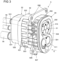
- Fig. 3
- eine Ansicht eines Ausführungsbeispiels eines Steckverbinderteils, mit einem Gehäuseteil, einem Verbinderteil und einem zum Festlegen eines Abdeckelements an dem Verbinderteil dienenden Rahmenteils;
- Fig. 4
- eine Ansicht des Gehäuseteils und des Verbinderteils vor Ansetzen aneinander;
- Fig. 5
- eine Ansicht des Gehäuseteils und des Verbinderteils in einer aneinander angesetzten Stellung;
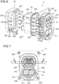
- Fig. 6
- eine Ansicht des Gehäuseteils und des Verbinderteils vor Ansetzen des Rahmenteils;
- Fig. 7
- eine Vorderansicht des Steckverbinderteils;
- Fig. 8A
- eine Schnittansicht entlang der Linie A-A gemäß
Fig. 7 ; - Fig. 8B
- eine vergrößerte Ansicht im Ausschnitt A1 gemäß
Fig. 8A ; - Fig. 9A
- eine Schnittansicht entlang der Linie B-B gemäß
Fig. 7 ; und - Fig. 9B
- eine vergrößerte Ansicht im Ausschnitt A2 gemäß
Fig. 9A . -
Fig. 1 zeigt eine Ladestation 1, die zum Aufladen eines elektrisch angetriebenen Fahrzeugs 4, auch bezeichnet als Elektrofahrzeug, dient. Die Ladestation 1 ist dazu ausgestaltet, einen Ladestrom in Form eines Wechselstroms oder eines Gleichstroms zur Verfügung zu stellen und weist ein Kabel 2 auf, das mit einem Ende 201 mit der Ladestation 1 und mit einem anderen Ende 200 mit einem Gegensteckverbinderteil 3 in Form eines Ladesteckers verbunden ist. - Das Gegensteckverbinderteil 3 kann steckend mit einem zugeordneten Steckverbinderteil 5 in Form einer Ladebuchse an dem Fahrzeug 4 in Eingriff gebracht werden. Auf diese Weise kann die Ladestation 1 elektrisch mit dem Fahrzeug 4 verbunden werden, um Ladeströme von der Ladestation 1 hin zu dem Fahrzeug 4 zu übertragen.
- Ein Ausführungsbeispiel eines Steckverbinderteils 5 in Form einer zum Beispiel an einem Fahrzeug 4 anzuordnenden Ladebuchse zeigt
Fig. 2 . Das Steckverbinderteil 5 in Form der Ladebuchse weist ein Gehäuseteil 50 auf, das über Befestigungsstellen 506 an einem zugeordneten Fahrzeug zu befestigen ist und an dem ein Verbinderteil 51 zur Ausbildung eines Steckgesichtes angeordnet ist. Das Verbinderteil 51 bildet Steckabschnitte 510, 511 aus, die entlang einer Steckrichtung E (sieheFig. 1 ) steckend mit einem zugeordneten Gegensteckverbinderteil 3 verbunden werden können, um elektrische Kontakte 512, 513 an den Steckabschnitten 510, 511 elektrisch mit dem Gegensteckverbinderteil 3 zu kontaktieren und darüber eine elektrische Verbindung zwischen der Ladestation 1 und dem Fahrzeug 4 herzustellen. - Bei dem dargestellten Ausführungsbeispiel sind an einem oberen, ersten Steckabschnitt 510 elektrische Kontaktelemente 512 angeordnet, die insbesondere zum Übertragen eines Ladestroms in Form eines (gegebenenfalls mehrphasigen) Wechselstroms dienen können. An einem unteren, zweiten Steckabschnitt 511 sind demgegenüber Kontaktelemente 513 angeordnet, über die ein Ladestrom in Form eines Gleichstroms hin zu dem Fahrzeug 4 übertragen werden kann. Zusätzlich zu Lastkontakten zum Übertragen eines Ladestroms können an den Steckabschnitten 510, 511 Signalkontakte zum Übertragen von Steuersignalen vorgesehen sein.
- Bei einem Steckverbinderteil 5 in Form einer an einem Fahrzeug 4 anzuordnenden Ladebuchse, wie sie beispielhaft in
Fig. 2 dargestellt ist, ist das Gehäuseteil 50 üblicherweise für unterschiedliche Fahrzeuge in seiner Gestalt variabel. Das durch das Verbinderteil 51 bereitgestellte Steckgesicht ist demgegenüber genormt, sodass das Steckverbinderteil 5 mit einem entsprechend genormten, komplementären Ladestecker 3 zum Aufladen des Fahrzeugs 4 in Eingriff gebracht werden kann. - Um das Steckverbinderteil 5 zu montieren, muss das Verbinderteil 51 an dem Gehäuseteil 50 befestigt werden, wobei wünschenswert ist, eine vordefinierte Schnittstelle zur Verbindung zu verwenden, sodass für das Verbinderteil 51 ein Gleichteil verwendet werden kann, das mit unterschiedlich gestalteten Gehäuseteilen 50 verbunden werden kann. Dies ermöglicht, ein einheitliches Verbinderteil 51 an ganz unterschiedlichen Gehäuseteilen 50 zu verwenden, was die Teilevielfalt reduziert und zudem den Aufwand und die Kosten bei Konzipierung eines Steckverbinderteils 5 verringert, weil Anpassungen an dem Verbinderteil 51 nicht mehr erforderlich sind.
- Ein Ausführungsbeispiel eines Steckverbinderteils 5 zeigen
Fig. 3 bis 9A ,9B . Das Steckverbinderteil 5 weist bei dem dargestellten Ausführungsbeispiel ein Gehäuseteil 50 auf, das rastend mit einem Verbinderteil 51 zu verbinden ist derart, dass Steckabschnitte 510, 511 des Verbinderteils 51 in zugeordneten Aufnahmeöffnungen 500, 501 an der Vorderseite 508 des Gehäuseteils 50 zu liegen kommen und somit an der Vorderseite 508 ein Steckgesicht zum steckenden Verbinden mit einem zugeordneten Gegensteckverbinderteil 3 ausbilden. - An dem Verbinderteil 51 ist ein Abdeckelement 53 angeordnet, das zum feuchtigkeitsdichten Einfassen von elektrischen Leitungen 54 an dem Verbinderteil 51 dient und dazu über ein Rahmenteil 52 an dem Verbinderteil 51 gehalten ist. Das Abdeckelement 53 weist einen aus einem elastisch verformbaren Material gefertigten Tüllenkörper 530 auf, an dem Leitungsabgänge 531 zum Aufnehmen von elektrischen Leitungen 54 geformt sind, sodass die elektrischen Leitungen 54 in das Abdeckelement 53 eingeführt und an dem Verbinderteil 51 in feuchtigkeitsdichter Weise eingefasst sind, wie dies insbesondere aus
Fig. 3 ersichtlich ist. - Zur Montage der Steckverbinderteils 5 werden das Gehäuseteil 50, das Verbinderteil 51 und das Rahmenteil 52 rastend miteinander verbunden, indem das Gehäuseteil 50, das Verbinderteil 51 und das Rahmenteil 52 aneinander angesetzt werden. Das Rahmenteil 52 umgreift hierbei mit einem Rahmenkörper 520 einen Randabschnitt 532 des Abdeckelements 53 (siehe
Fig. 6 in Zusammenschau mitFig. 8B und9B ), sodass über das Rahmenteil 52 das Abdeckelement 53 an dem Verbinderteil 51 fixiert wird. - Bei dem dargestellten Ausführungsbeispiel wird zunächst das Gehäuseteil 50 rastend mit dem Verbinderteil 51 verbunden, wie dies in
Fig. 4 und 5 dargestellt ist. Das Gehäuseteil 50 weist einen Gehäusekörper 502 auf, von dem axial entlang einer ersten Montagerichtung M1 Rastelemente 503 nach Art von Rastfingern erstreckt sind, die dazu dienen, mit zugeordneten ersten Gegenrastelementen 515 an einem Gehäuse 514 des Verbinderteils 51 zu verrasten, um das Gehäuseteil 50 und das Verbinderteil 51 zueinander festzulegen. Mehrere erste Rastelemente 503 sind hierbei umfänglich verteilt um die ersten Montagerichtung M1 an dem Gehäusekörper 502 geformt, wobei jedes Rastelement 503 einen Rastkopf 504 zum Verrasten mit einem jeweils zugeordneten Gegenrastelement 515 und ein von dem Rastkopf 504 vorstehendes Eingriffselement 505 aufweist. - Zum Verbinden des Gehäuseteils 50 mit dem Verbinderteil 51 wird das Gehäuseteil 50 in die Montagerichtung M1 an das Verbinderteil 51 angesetzt, sodass die Rastelemente 503 des Gehäuseteils 50 mit ihren Rastköpfen 504 auf Auflaufschrägen 516 an den Gegenrastelementen 515 des Verbinderteils 51 auflaufen und somit rastend mit den Gegenrastelementen 515 in Eingriff gelangen, wie dies im Übergang von
Fig. 4 hin zuFig. 5 ersichtlich ist. - Bei dem dargestellten Ausführungsbeispiel wird nach Verbinden des Gehäuseteils 50 mit dem Verbinderteil 51 das Abdeckelement 53 an eine dem Gehäuseteil 50 abgewandte Seite des Verbinderteils 51 angesetzt, wie dies aus
Fig. 6 ersichtlich ist, und das Rahmenteil 52 wird zum Beispiel in eine der ersten Montagerichtung M1 entgegengesetzte, zweite Montagerichtung M2 an dem Verbinderteil 51 angeordnet. Das Rahmenteil 52 weist zweite Rastelemente 521 auf, die axial entlang der Montagerichtung M2 von einem umfänglich um die Montagerichtung M2 erstreckten, geschlossenen Rahmenkörper 520 vorstehen und nach Art von Rastfingern mit an den Rastelementen 521 geformten Rastköpfen 522 ausgebildet sind. - Bei Ansetzen des Rahmenteils 52 an das Verbinderteil 51 laufen die Rastelemente 521 mit ihren Rastköpfen 522 auf Auflaufschrägen 518 an zugeordneten zweiten Gegenrastelementen 517 des Verbinderteils 51 auf. In verbundener Stellung sind die Rastelemente 521 mit ihren Rastköpfen 522 mit den zugeordneten Gegenrastelementen 517 an dem Gehäuse 514 des Verbinderteils 51 formschlüssig verrastet, sodass das Rahmenteil 52 mit dem Verbinderteil 51 verbunden und darüber das Abdeckelement 53 zu dem Verbinderteil 51 festgelegt ist.
- In montierter Stellung des Steckverbinderteils 5, dargestellt in
Fig. 3 , greifen die Rastelemente 503 des Gehäuseteils 50 und die Rastelemente 521 des Rahmenteils 52 alternierend ineinander, sodass zwischen zwei Rastelementen 503 des Gehäuseteils 50 ein Rastelement 521 des Rahmenteils 52 zu liegen kommt und umgekehrt. - Die ersten Gegenrastelemente 515 und die zweiten Gegenrastelemente 517 sind jeweils als radial von dem Gehäuse 514 vorstehende, starre Rastvorsprünge an dem Verbinderteil 51 geformt. Die ersten Gegenrastelemente 515 und die zweiten Gegenrastelemente 517 sind hierbei alternierend zueinander angeordnet derart, dass auf ein erstes Gegenrastelement 515 ein zweites Gegenrastelement 517 folgt und umgekehrt, wie dies insbesondere aus
Fig. 4 ersichtlich ist. - Wie aus der Schnittansicht gemäß
Fig. 8A und der vergrößerten Detailansicht gemäßFig. 8B ersichtlich ist, steht ein jedes Rastelement 503 des Gehäuseteils 50 in montierter Stellung des Steckverbinderteils 5 formschlüssig mit einem zugeordneten Gegenrastelement 515 des Verbinderteils 51 in Eingriff. Zwischen dem Gehäuseteil 50 und dem Verbinderteil 51 ist hierbei ein Dichtelement 519 angeordnet (das vor Verbinden des Gehäuseteils 50 mit dem Verbinderteil 51 an dem Verbinderteil 51 erstreckt ist, wie dies ausFig. 4 ersichtlich ist), das einen Übergang zwischen dem Gehäuseteil 50 und dem Verbinderteil 51 feuchtigkeitsdicht abdichtet und zudem eine elastische Vorspannung axial entlang der Montagerichtung M1 bewirkt, die dazu führt, dass die Rastelemente 503 und die Gegenrastelemente 515 unter elastischer axialer Vorspannung miteinander in Eingriff und somit spielfrei entlang der Montagerichtung M1 zueinander gehalten sind. - Wie aus der Schnittansicht gemäß
Fig. 9A und der vergrößerten Detailansicht gemäßFig. 9B ersichtlich ist, steht ein jedes Rastelement 521 des Rahmenteils 52 in der montierten Stellung des Steckverbinderteils 5 formschlüssig mit einem zugeordneten Gegenrastelement 517 des Verbinderteils 51 in Eingriff. Zwischen einer innen in dem Rahmenteil 52 geformten, umlaufenden Anlagekontur 524 und dem Gehäuse 514 des Verbinderteils 51 kommt dabei der Randabschnitt 532 des Abdeckelements 53 zu liegen, wie dies ausFig. 9B ersichtlich ist. Der Übergang zwischen dem Abdeckelement 53 und dem Verbinderteil 51 ist darüber abgedichtet, wobei der Randabschnitt 532 zusätzlich eine elastische Vorspannung zwischen dem Rahmenteil 52 und dem Verbinderteil 51 bewirkt, die dazu führt, dass die Rastelemente 521 und die Gegenrastelemente 517 spielfrei entlang der Montagerichtung M2 miteinander in Eingriff gehalten werden. - Das Rahmenteil 52 dient dazu, das Abdeckelement 53 zu dem Verbinderteil 51 festzulegen, wobei über die Anlagekontur 524 eine Klemmwirkung auf den Randabschnitt 532 für eine feuchtigkeitsdichte Abdichtung am Übergang zu dem Verbinderteil 51 bewirkt wird. Das Rahmenteil 52 ist hierbei zusätzlich dazu ausgebildet, die Verrastung zwischen dem Gehäuseteil 50 und dem Verbinderteil 51 zu verriegeln, indem das Rahmenteil 52 mit seinem Rahmenkörper 520, insbesondere mit zwischen den Rastelementen 521 geformten Randabschnitten 523 die Eingriffselemente 505 an den Rastelementen 503 des Gehäuseteils 50 umgreift, wie dies aus
Fig. 8B ersichtlich ist. Die Rastelemente 503 sind somit in ihrem Eingriff mit den zugeordneten Gegenrastelementen 515 des Verbinderteils 51 gesichert, sodass die Verbindung zwischen dem Gehäuseteil 50 und dem Verbinderteil 51 nicht ohne weiteres, jedenfalls nicht ohne Lösen des Rahmenteils 52, aufgehoben werden kann. - Der der Erfindung zugrunde liegende Gedanke ist nicht auf die vorangehend geschilderten Ausführungsbeispiele beschränkt, sondern lässt sich auch in gänzlich andersgearteter Weise verwirklichen.
- Ein Steckverbinderteil der beschriebenen Art kann eine Ladebuchse an einem Elektrofahrzeug verwirklichen, kann aber auch zum Beispiel einen über ein Ladekabel mit einer Ladestation verbundenen Ladestecker ausbilden.
- Darüber hinaus kann ein solches Steckverbinderteil auch unabhängig von einem Ladesystem zum Aufladen eines Elektrofahrzeugs zum Einsatz kommen.
- Über ein solches Steckverbinderteil können Lastströme in Form eines Gleichstroms oder in Form eines Wechselstroms übertragen werden.
- Das Verbinderteil und das Gehäuseteil des Steckverbinderteils können ganz unterschiedlich ausgestaltet sein. Insofern sind das Verbinderteil und das Gehäuseteil insbesondere nicht auf die konkret dargestellten Ausgestaltungen beschränkt.
- Bei dem dargestellten Ausführungsbeispiel dient das Rahmenteil (auch) dazu, die rastende Verbindung zwischen dem Gehäuseteil und dem Verbinderteil zu verriegeln. Umgekehrt ist auch denkbar und möglich, insbesondere bei einer Ausgestaltung, bei der das Rahmenteil zunächst mit dem Verbinderteil verbunden und sodann das Gehäuseteil angesetzt wird, das Gehäuseteil dazu auszugestalten, die rastende Verbindung zwischen dem Verbinderteil und dem Rahmenteil zu verriegeln, indem das Gehäuseteil Rastelemente des Rahmenteils umgreift und somit in Eingriff mit zugeordneten Gegenrastelementen des Verbinderteils hält.
-
- 1
- Ladestation
- 2
- Ladekabel
- 200,201
- Ende
- 3
- Gegensteckverbinderteil (Ladestecker)
- 4
- Fahrzeug
- 5
- Steckverbinderteil (Ladebuchse)
- 50
- Gehäuseteil
- 500, 501
- Aufnahmeöffnung
- 502
- Gehäusekörper
- 503
- Rastelement
- 504
- Rastkopf
- 505
- Eingriffselement
- 506
- Befestigungselement
- 507
- Anschluss
- 508
- Vorderseite
- 51
- Verbinderteil
- 510, 511
- Steckabschnitt
- 512,513
- Kontaktelement
- 514
- Gehäuse
- 515
- Gegenrastelement
- 516
- Auflaufschräge
- 517
- Gegenrastelement
- 518
- Auflaufschräge
- 519
- Dichtelement
- 52
- Rahmenteil
- 520
- Rahmenkörper
- 521
- Rastelement
- 522
- Rastkopf
- 523
- Randabschnitt
- 524
- Anlagekontur
- 53
- Abdeckelement
- 530
- Tüllenkörper
- 531
- Leitungsabgang
- 532
- Randabschnitt
- 54
- Leitung
- E
- Einsteckrichtung
- M 1, M2
- Montagerichtung
Claims (15)
- Steckverbinderteil (5) zum Verbinden mit einem Gegensteckverbinderteil (3), mit einem Gehäuseteil (50), einem mit dem Gehäuseteil (50) zu verrastenden Verbinderteil (51), das einen Steckabschnitt (510, 511) aufweist, an dem zumindest ein Kontaktelement (512, 513) zum steckenden Verbinden mit dem Gegensteckverbinderteil (3) angeordnet ist, und einem Abdeckelement (53), das mit dem Verbinderteil (51) zu verbinden ist und zumindest einen Leitungsabgang (531) zum Aufnehmen einer mit dem Verbinderteil (51) verbundenen elektrischen Leitung (54) aufweist, gekennzeichnet durch ein Rahmenteil (52), das mit dem Verbinderteil (51) rastend zu verbinden ist und ausgebildet ist, in einer an das Verbinderteil (51) angesetzten Stellung das Abdeckelement (53) zu dem Verbinderteil (51) festzulegen.
- Steckverbinderteil (5) nach Anspruch 1, dadurch gekennzeichnet, dass in der an das Verbinderteil (51) angesetzten Stellung des Rahmenteils (52) das Abdeckelement (53) mit einem Randabschnitt (532) an dem Verbinderteil (51) anliegt und über das Rahmenteil (52) an dem Verbinderteil (51) gehalten ist.
- Steckverbinderteil (5) nach Anspruch 1 oder 2, dadurch gekennzeichnet, dass das Gehäuseteil (50) zumindest ein erstes Rastelement (503) und das Verbinderteil (51) zumindest ein erstes Gegenrastelement (515) aufweisen, wobei das zumindest eine erste Rastelement (503) und das zumindest eine erste Gegenrastelement (515) zum Verbinden des Verbinderteils (51) mit dem Gehäuseteil (50) entlang einer Montagerichtung (M1, M2) rastend miteinander in Eingriff bringbar sind.
- Steckverbinderteil (5) nach Anspruch 3, dadurch gekennzeichnet, dass das zumindest eine erste Gegenrastelement (515) eine Auflaufschräge (518) für das zumindest eine erste Rastelement (503) des Gehäuseteils (50) zum Auflaufen entlang der Montagerichtung (M1, M2) aufweist.
- Steckverbinderteil (5) nach Anspruch 3 oder 4, dadurch gekennzeichnet, dass das Gehäuseteil (50) einen Gehäusekörper (502) aufweist, wobei das zumindest eine erste Rastelement (503) als entlang der Montagerichtung (M1, M2) von dem Gehäusekörper (502) erstreckter Rastfinger ausgebildet ist.
- Steckverbinderteil (5) nach einem der Ansprüche 3 bis 5, dadurch gekennzeichnet, dass das Rahmenteil (52) ausgebildet ist, auf das zumindest eine erste Rastelement (503) des Gehäuseteils (50) einzuwirken, um die rastende Verbindung zwischen dem Gehäuseteil (50) und dem Verbinderteil (51) gegen ein Lösen zu verriegeln.
- Steckverbinderteil (5) nach einem der vorangehenden Ansprüche, dadurch gekennzeichnet, dass das Rahmenteil (52) zumindest ein zweites Rastelement (521) und das Verbinderteil (51) zumindest ein zweites Gegenrastelement (517) aufweisen, wobei das zumindest eine zweite Rastelement (521) und das zumindest eine zweite Gegenrastelement (517) zum Verbinden des Rahmenteils (52) mit dem Verbinderteil (51) entlang einer Montagerichtung (M1, M2) rastend miteinander in Eingriff bringbar sind.
- Steckverbinderteil (5) nach Anspruch 7, dadurch gekennzeichnet, dass das zumindest eine zweite Gegenrastelement (517) eine Auflaufschräge (518) für das zumindest eine zweite Rastelement (521) des Rahmenteils (52) zum Auflaufen entlang der Montagerichtung (M1, M2) aufweist.
- Steckverbinderteil (5) nach Anspruch 7 oder 8, dadurch gekennzeichnet, dass das Rahmenteil (52) einen Rahmenkörper (520) aufweist, wobei das zumindest eine zweite Rastelement (521) als entlang der Montagerichtung (M1, M2) von dem Rahmenkörper (520) erstreckter Rastfinger ausgebildet ist.
- Steckverbinderteil (5) nach einem der Ansprüche 7 bis 9, dadurch gekennzeichnet, dass das Gehäuseteil (50) ausgebildet ist, auf das zumindest eine zweite Rastelement (521) des Rahmenteils (52) einzuwirken, um die rastende Verbindung zwischen dem Verbinderteil (51) und dem Rahmenteil (52) gegen ein Lösen zu verriegeln.
- Steckverbinderteil (5) nach einem der vorangehenden Ansprüche, dadurch gekennzeichnet, dass das Gehäuseteil (50) mehrere erste Rastelemente (503) und das Rahmenteil (52) mehrere zweite Rastelemente (521) aufweisen, wobei in einer montierten Stellung des Steckverbinderteils (5), in der das Gehäuseteil (50), das Verbinderteil (51) und das Rahmenteil (52) miteinander verbunden sind, ein erstes Rastelement (503) zwischen zwei zweiten Rastelementen (521) und/oder ein zweites Rastelement (521) zwischen zwei ersten Rastelementen (503) aufgenommen ist.
- Steckverbinderteil (5) nach einem der vorangehenden Ansprüche, dadurch gekennzeichnet, dass das Verbinderteil (51) ein Gehäuse (514) aufweist, an dem erste Gegenrastelemente (515) zum rastenden Verbinden mit dem Gehäuseteil (50) und zweite Gegenrastelemente (517) zum rastenden Verbinden mit dem Rahmenteil (52) entlang einer Umfangsrichtung alternierend zueinander angeordnet sind.
- Steckverbinderteil (5) nach einem der vorangehenden Ansprüche, gekennzeichnet durch ein Dichtelement (519), das bei mit dem Gehäuseteil (50) verrasteten Verbinderteil (51) einen Übergang zwischen dem Gehäuseteil (50) und dem Verbinderteil (51) feuchtigkeitsdicht abdichtet.
- Verfahren zum Montieren eines Steckverbinderteils (5) zum Verbinden mit einem Gegensteckverbinderteil (3), bei dem ein Verbinderteil (51), das einen Steckabschnitt (510, 511) aufweist, an dem zumindest ein Kontaktelement (512, 513) zum steckenden Verbinden mit dem Gegensteckverbinderteil (3) angeordnet ist, mit einem Gehäuseteil (50) verrastet und ein Abdeckelement (53), das zumindest einen Leitungsabgang (531) zum Aufnehmen einer mit dem Verbinderteil (51) verbundenen elektrischen Leitung (54) aufweist, mit dem Verbinderteil (51) verbunden wird, dadurch gekennzeichnet, dass ein Rahmenteil (52) mit dem Verbinderteil (51) rastend verbunden wird, wobei das Rahmenteil (52) in einer an das Verbinderteil (51) angesetzten Stellung das Abdeckelement (53) zu dem Verbinderteil (51) festlegt.
- Verfahren nach Anspruch 14, dadurch gekennzeichnet, dass zunächst das Verbinderteil (51) mit dem Gehäuseteil (50) verrastet und danach das Rahmenteil (52) mit dem Verbinderteil (51) verbunden wird oder zunächst das Rahmenteil (52) mit dem Verbinderteil (51) verbunden und danach das Verbinderteil (51) mit dem Gehäuseteil (50) verrastet wird.
Applications Claiming Priority (2)
| Application Number | Priority Date | Filing Date | Title |
|---|---|---|---|
| BE20195016A BE1026967B1 (de) | 2019-01-11 | 2019-01-11 | Steckverbinderteil mit einem mit einem Gehäuseteil zu verbindenden Verbinderteil |
| PCT/EP2019/085344 WO2020144005A1 (de) | 2019-01-11 | 2019-12-16 | Steckverbinderteil mit einem mit einem gehäuseteil zu verbindenden verbinderteil |
Publications (2)
| Publication Number | Publication Date |
|---|---|
| EP3909098A1 EP3909098A1 (de) | 2021-11-17 |
| EP3909098B1 true EP3909098B1 (de) | 2023-02-01 |
Family
ID=65324120
Family Applications (1)
| Application Number | Title | Priority Date | Filing Date |
|---|---|---|---|
| EP19818099.4A Active EP3909098B1 (de) | 2019-01-11 | 2019-12-16 | Steckverbinderteil mit einem mit einem gehäuseteil zu verbindenden verbinderteil |
Country Status (6)
| Country | Link |
|---|---|
| US (1) | US11749934B2 (de) |
| EP (1) | EP3909098B1 (de) |
| CN (1) | CN113287231B (de) |
| BE (1) | BE1026967B1 (de) |
| ES (1) | ES2938034T3 (de) |
| WO (1) | WO2020144005A1 (de) |
Families Citing this family (10)
| Publication number | Priority date | Publication date | Assignee | Title |
|---|---|---|---|---|
| DE102020130410A1 (de) * | 2020-11-18 | 2022-05-19 | Phoenix Contact E-Mobility Gmbh | Ladedose zur Montage in einer Karosserie eines zumindest teilweise elektrisch angetriebenen Kraftfahrzeugs |
| DE102021115051A1 (de) * | 2021-06-10 | 2022-12-15 | Te Connectivity Germany Gmbh | Adaptersystem zur elektrischen Verbindung eines Steckverbinders einer Verkabelung mit unterschiedlichen Kontaktanordnungen verschiedener Ladebuchsen |
| US20230085351A1 (en) * | 2021-09-10 | 2023-03-16 | Aptiv Technologies Limited | Serviceable power inlet connector |
| CN116080770A (zh) * | 2021-11-05 | 2023-05-09 | 本田技研工业(中国)投资有限公司 | 充电装置或放电装置及车辆 |
| US12496918B2 (en) * | 2022-06-09 | 2025-12-16 | Japan Aviation Electronics Industry, Limited | Charging connector |
| CN114824853B (zh) * | 2022-06-27 | 2022-10-28 | 深圳众城卓越科技有限公司 | 用于pcb功率板导大电流接线的压接组件及其压接方法 |
| WO2024154346A1 (ja) * | 2023-01-20 | 2024-07-25 | 住友電気工業株式会社 | コネクタ、嵌合間口、および取付部材 |
| EP4485704B1 (de) * | 2023-06-27 | 2025-08-06 | Neutrik AG | Einbausteckverbindergehäuse aus weichem material |
| EP4527680A1 (de) * | 2023-09-21 | 2025-03-26 | ITT Cannon GmbH | Ladesteckdose für ein elektrofahrzeug, verfahren zur herstellung der ladesteckdose |
| CN117549774A (zh) * | 2023-11-29 | 2024-02-13 | 浙江力达电器股份有限公司 | 电动汽车充电口 |
Family Cites Families (15)
| Publication number | Priority date | Publication date | Assignee | Title |
|---|---|---|---|---|
| JP2000311741A (ja) * | 1999-04-28 | 2000-11-07 | Sumitomo Wiring Syst Ltd | 分割コネクタ |
| US6939174B2 (en) * | 2003-07-01 | 2005-09-06 | Hon Hai Precision Ind. Co., Ltd. | Cable assembly with internal circuit modules |
| DE102009036411B3 (de) | 2009-08-06 | 2011-02-03 | Tyco Electronics Amp Gmbh | Kombinierter elektrischer Steckverbinder mit Toleranzausgleich |
| US9013319B2 (en) | 2011-08-23 | 2015-04-21 | Lear Corporation | Vehicle inlet for use in charging a battery of an electric vehicle (EV) or a hybrid electric vehicle (HEV) |
| DE102012019605A1 (de) | 2012-10-05 | 2014-04-10 | Audi Ag | Modulsystem für eine Ladevorrichtung, Ladevorrichtung sowie Fahrzeug mit einer aus dem Modulsystem erstellten Ladevorrichtung |
| JP5981294B2 (ja) | 2012-10-12 | 2016-08-31 | 矢崎総業株式会社 | 充電インレット装置 |
| CN105144498B (zh) * | 2013-03-19 | 2017-10-13 | 住友电装株式会社 | 车辆侧连接器 |
| DE102013112991A1 (de) | 2013-11-25 | 2015-06-11 | Phoenix Contact Gmbh & Co. Kg | Ladestecker zum Laden eines Elektrofahrzeugs |
| DE102013019882B4 (de) | 2013-11-28 | 2025-10-02 | Phoenix Contact E-Mobility Gmbh | Ladekabelstecker |
| DE102014215077B4 (de) | 2014-07-31 | 2021-11-18 | Volkswagen Aktiengesellschaft | Ladesteckdose und modulares Ladesteckdosensystem |
| DE102016105470A1 (de) | 2016-03-23 | 2017-09-28 | Te Connectivity Germany Gmbh | Leistungselektrische Kontakteinrichtung; austauschbares, leistungselektrisches Kontaktmodul sowie leistungselektrischer Verbinder |
| LU93308B1 (de) | 2016-11-16 | 2018-06-07 | Phoenix Contact E Mobility Gmbh | Steckverbinderteil, insbesondere zum Übertragen eines Ladestroms zum Aufladen eines Elektrofahrzeugs |
| CN206498000U (zh) | 2017-02-08 | 2017-09-15 | 安费诺科技(珠海)有限公司 | 一种板式电源连接器 |
| CN207052813U (zh) * | 2017-05-12 | 2018-02-27 | 泰科电子(上海)有限公司 | 插座壳体组件及插座 |
| CN107394520B (zh) * | 2017-09-05 | 2023-05-05 | 东台正耀精密技术有限公司 | 电连接器组合 |
-
2019
- 2019-01-11 BE BE20195016A patent/BE1026967B1/de not_active IP Right Cessation
- 2019-12-16 WO PCT/EP2019/085344 patent/WO2020144005A1/de not_active Ceased
- 2019-12-16 ES ES19818099T patent/ES2938034T3/es active Active
- 2019-12-16 US US17/421,401 patent/US11749934B2/en active Active
- 2019-12-16 CN CN201980088584.3A patent/CN113287231B/zh active Active
- 2019-12-16 EP EP19818099.4A patent/EP3909098B1/de active Active
Also Published As
| Publication number | Publication date |
|---|---|
| EP3909098A1 (de) | 2021-11-17 |
| BE1026967B1 (de) | 2020-08-13 |
| US11749934B2 (en) | 2023-09-05 |
| CN113287231A (zh) | 2021-08-20 |
| ES2938034T3 (es) | 2023-04-04 |
| CN113287231B (zh) | 2024-02-27 |
| WO2020144005A1 (de) | 2020-07-16 |
| BE1026967A1 (de) | 2020-08-06 |
| US20220102904A1 (en) | 2022-03-31 |
Similar Documents
| Publication | Publication Date | Title |
|---|---|---|
| EP3909098B1 (de) | Steckverbinderteil mit einem mit einem gehäuseteil zu verbindenden verbinderteil | |
| EP2208259B1 (de) | Stecker und steckverbindung für roboter | |
| EP3963217B1 (de) | Befestigungsanordnung mit dämpfungswirkung und bauteilverbindung mit der befestigungsanordnung | |
| DE2807366A1 (de) | Verbinderanordnung | |
| EP3637560B1 (de) | Steckverbinderteil mit einem mit einem gehäuseteil zu verbindenden inletteil | |
| DE102012203459A1 (de) | Mehrpolige Steckverbindungseinheit für Dreiphasen-Wechselstromsysteme | |
| DE102015120921B4 (de) | Steckverbinder und Steckerverbinderanordnung | |
| LU93308B1 (de) | Steckverbinderteil, insbesondere zum Übertragen eines Ladestroms zum Aufladen eines Elektrofahrzeugs | |
| WO2018192962A1 (de) | Baugruppe für ein steckverbinderteil mit einem kontakteinsatz und einem erdungselement | |
| EP3127194A1 (de) | Mehrpoliges elektrisches steckverbinderteil | |
| DE102019100580B4 (de) | Steckverbinderteil mit einem mit einem Gehäuseteil zu verbindenden Verbinderteil sowie Verfahren zum Montieren eines Steckverbinderteils | |
| WO2021028077A1 (de) | Buchse xlr 8+2 pcb | |
| DE102011112283A1 (de) | Modulares elektrisches Steckverbindersystem für Solaranlagen | |
| WO2024153609A1 (de) | Sensorbaugruppe für ein fahrzeug | |
| WO2019076620A1 (de) | Steckverbinderteil mit einem verriegelungselement | |
| EP1760838A1 (de) | Elektrisches Steckverbinderteil | |
| DE102016121847A1 (de) | Steckverbinderteil mit einem Abflussstutzen | |
| DE4224155C2 (de) | Elektrische Steckverbinderanordnung | |
| DE202004015082U1 (de) | Einheit zur Installation einer elektrischen Leitung | |
| EP3895254B1 (de) | Steckverbinderteil zur kontaktierung in mehreren raumrichtungen | |
| DE102011056335B4 (de) | Steckeradapter | |
| EP4435981B1 (de) | Gehäusebaugruppe für einen steckverbinder und verfahren zur montage eines steckverbinders | |
| DE102024202796A1 (de) | Steckverbinder und Kappe | |
| WO2025195697A1 (de) | Steckverbinder und kappe | |
| DE102024202797A1 (de) | Steckverbinder und Kappe |
Legal Events
| Date | Code | Title | Description |
|---|---|---|---|
| STAA | Information on the status of an ep patent application or granted ep patent |
Free format text: STATUS: UNKNOWN |
|
| STAA | Information on the status of an ep patent application or granted ep patent |
Free format text: STATUS: THE INTERNATIONAL PUBLICATION HAS BEEN MADE |
|
| PUAI | Public reference made under article 153(3) epc to a published international application that has entered the european phase |
Free format text: ORIGINAL CODE: 0009012 |
|
| STAA | Information on the status of an ep patent application or granted ep patent |
Free format text: STATUS: REQUEST FOR EXAMINATION WAS MADE |
|
| 17P | Request for examination filed |
Effective date: 20210701 |
|
| AK | Designated contracting states |
Kind code of ref document: A1 Designated state(s): AL AT BE BG CH CY CZ DE DK EE ES FI FR GB GR HR HU IE IS IT LI LT LU LV MC MK MT NL NO PL PT RO RS SE SI SK SM TR |
|
| DAV | Request for validation of the european patent (deleted) | ||
| DAX | Request for extension of the european patent (deleted) | ||
| GRAP | Despatch of communication of intention to grant a patent |
Free format text: ORIGINAL CODE: EPIDOSNIGR1 |
|
| STAA | Information on the status of an ep patent application or granted ep patent |
Free format text: STATUS: GRANT OF PATENT IS INTENDED |
|
| INTG | Intention to grant announced |
Effective date: 20220831 |
|
| GRAS | Grant fee paid |
Free format text: ORIGINAL CODE: EPIDOSNIGR3 |
|
| GRAA | (expected) grant |
Free format text: ORIGINAL CODE: 0009210 |
|
| STAA | Information on the status of an ep patent application or granted ep patent |
Free format text: STATUS: THE PATENT HAS BEEN GRANTED |
|
| AK | Designated contracting states |
Kind code of ref document: B1 Designated state(s): AL AT BE BG CH CY CZ DE DK EE ES FI FR GB GR HR HU IE IS IT LI LT LU LV MC MK MT NL NO PL PT RO RS SE SI SK SM TR |
|
| REG | Reference to a national code |
Ref country code: GB Ref legal event code: FG4D Free format text: NOT ENGLISH |
|
| REG | Reference to a national code |
Ref country code: CH Ref legal event code: EP Ref country code: AT Ref legal event code: REF Ref document number: 1547165 Country of ref document: AT Kind code of ref document: T Effective date: 20230215 |
|
| REG | Reference to a national code |
Ref country code: DE Ref legal event code: R096 Ref document number: 502019006931 Country of ref document: DE |
|
| REG | Reference to a national code |
Ref country code: IE Ref legal event code: FG4D Free format text: LANGUAGE OF EP DOCUMENT: GERMAN |
|
| REG | Reference to a national code |
Ref country code: SE Ref legal event code: TRGR |
|
| REG | Reference to a national code |
Ref country code: ES Ref legal event code: FG2A Ref document number: 2938034 Country of ref document: ES Kind code of ref document: T3 Effective date: 20230404 |
|
| REG | Reference to a national code |
Ref country code: LT Ref legal event code: MG9D |
|
| REG | Reference to a national code |
Ref country code: NL Ref legal event code: MP Effective date: 20230201 |
|
| P01 | Opt-out of the competence of the unified patent court (upc) registered |
Effective date: 20230525 |
|
| P02 | Opt-out of the competence of the unified patent court (upc) changed |
Effective date: 20230531 |
|
| PG25 | Lapsed in a contracting state [announced via postgrant information from national office to epo] |
Ref country code: RS Free format text: LAPSE BECAUSE OF FAILURE TO SUBMIT A TRANSLATION OF THE DESCRIPTION OR TO PAY THE FEE WITHIN THE PRESCRIBED TIME-LIMIT Effective date: 20230201 Ref country code: PT Free format text: LAPSE BECAUSE OF FAILURE TO SUBMIT A TRANSLATION OF THE DESCRIPTION OR TO PAY THE FEE WITHIN THE PRESCRIBED TIME-LIMIT Effective date: 20230601 Ref country code: NO Free format text: LAPSE BECAUSE OF FAILURE TO SUBMIT A TRANSLATION OF THE DESCRIPTION OR TO PAY THE FEE WITHIN THE PRESCRIBED TIME-LIMIT Effective date: 20230501 Ref country code: NL Free format text: LAPSE BECAUSE OF FAILURE TO SUBMIT A TRANSLATION OF THE DESCRIPTION OR TO PAY THE FEE WITHIN THE PRESCRIBED TIME-LIMIT Effective date: 20230201 Ref country code: LV Free format text: LAPSE BECAUSE OF FAILURE TO SUBMIT A TRANSLATION OF THE DESCRIPTION OR TO PAY THE FEE WITHIN THE PRESCRIBED TIME-LIMIT Effective date: 20230201 Ref country code: LT Free format text: LAPSE BECAUSE OF FAILURE TO SUBMIT A TRANSLATION OF THE DESCRIPTION OR TO PAY THE FEE WITHIN THE PRESCRIBED TIME-LIMIT Effective date: 20230201 Ref country code: HR Free format text: LAPSE BECAUSE OF FAILURE TO SUBMIT A TRANSLATION OF THE DESCRIPTION OR TO PAY THE FEE WITHIN THE PRESCRIBED TIME-LIMIT Effective date: 20230201 |
|
| PG25 | Lapsed in a contracting state [announced via postgrant information from national office to epo] |
Ref country code: PL Free format text: LAPSE BECAUSE OF FAILURE TO SUBMIT A TRANSLATION OF THE DESCRIPTION OR TO PAY THE FEE WITHIN THE PRESCRIBED TIME-LIMIT Effective date: 20230201 Ref country code: IS Free format text: LAPSE BECAUSE OF FAILURE TO SUBMIT A TRANSLATION OF THE DESCRIPTION OR TO PAY THE FEE WITHIN THE PRESCRIBED TIME-LIMIT Effective date: 20230601 Ref country code: GR Free format text: LAPSE BECAUSE OF FAILURE TO SUBMIT A TRANSLATION OF THE DESCRIPTION OR TO PAY THE FEE WITHIN THE PRESCRIBED TIME-LIMIT Effective date: 20230502 Ref country code: FI Free format text: LAPSE BECAUSE OF FAILURE TO SUBMIT A TRANSLATION OF THE DESCRIPTION OR TO PAY THE FEE WITHIN THE PRESCRIBED TIME-LIMIT Effective date: 20230201 |
|
| PG25 | Lapsed in a contracting state [announced via postgrant information from national office to epo] |
Ref country code: SM Free format text: LAPSE BECAUSE OF FAILURE TO SUBMIT A TRANSLATION OF THE DESCRIPTION OR TO PAY THE FEE WITHIN THE PRESCRIBED TIME-LIMIT Effective date: 20230201 Ref country code: RO Free format text: LAPSE BECAUSE OF FAILURE TO SUBMIT A TRANSLATION OF THE DESCRIPTION OR TO PAY THE FEE WITHIN THE PRESCRIBED TIME-LIMIT Effective date: 20230201 Ref country code: EE Free format text: LAPSE BECAUSE OF FAILURE TO SUBMIT A TRANSLATION OF THE DESCRIPTION OR TO PAY THE FEE WITHIN THE PRESCRIBED TIME-LIMIT Effective date: 20230201 Ref country code: DK Free format text: LAPSE BECAUSE OF FAILURE TO SUBMIT A TRANSLATION OF THE DESCRIPTION OR TO PAY THE FEE WITHIN THE PRESCRIBED TIME-LIMIT Effective date: 20230201 Ref country code: CZ Free format text: LAPSE BECAUSE OF FAILURE TO SUBMIT A TRANSLATION OF THE DESCRIPTION OR TO PAY THE FEE WITHIN THE PRESCRIBED TIME-LIMIT Effective date: 20230201 |
|
| REG | Reference to a national code |
Ref country code: DE Ref legal event code: R097 Ref document number: 502019006931 Country of ref document: DE |
|
| PG25 | Lapsed in a contracting state [announced via postgrant information from national office to epo] |
Ref country code: SK Free format text: LAPSE BECAUSE OF FAILURE TO SUBMIT A TRANSLATION OF THE DESCRIPTION OR TO PAY THE FEE WITHIN THE PRESCRIBED TIME-LIMIT Effective date: 20230201 |
|
| PLBE | No opposition filed within time limit |
Free format text: ORIGINAL CODE: 0009261 |
|
| STAA | Information on the status of an ep patent application or granted ep patent |
Free format text: STATUS: NO OPPOSITION FILED WITHIN TIME LIMIT |
|
| 26N | No opposition filed |
Effective date: 20231103 |
|
| PG25 | Lapsed in a contracting state [announced via postgrant information from national office to epo] |
Ref country code: SI Free format text: LAPSE BECAUSE OF FAILURE TO SUBMIT A TRANSLATION OF THE DESCRIPTION OR TO PAY THE FEE WITHIN THE PRESCRIBED TIME-LIMIT Effective date: 20230201 |
|
| REG | Reference to a national code |
Ref country code: CH Ref legal event code: PL |
|
| PG25 | Lapsed in a contracting state [announced via postgrant information from national office to epo] |
Ref country code: LU Free format text: LAPSE BECAUSE OF NON-PAYMENT OF DUE FEES Effective date: 20231216 |
|
| PG25 | Lapsed in a contracting state [announced via postgrant information from national office to epo] |
Ref country code: MC Free format text: LAPSE BECAUSE OF FAILURE TO SUBMIT A TRANSLATION OF THE DESCRIPTION OR TO PAY THE FEE WITHIN THE PRESCRIBED TIME-LIMIT Effective date: 20230201 |
|
| REG | Reference to a national code |
Ref country code: BE Ref legal event code: MM Effective date: 20231231 |
|
| PG25 | Lapsed in a contracting state [announced via postgrant information from national office to epo] |
Ref country code: MC Free format text: LAPSE BECAUSE OF FAILURE TO SUBMIT A TRANSLATION OF THE DESCRIPTION OR TO PAY THE FEE WITHIN THE PRESCRIBED TIME-LIMIT Effective date: 20230201 Ref country code: LU Free format text: LAPSE BECAUSE OF NON-PAYMENT OF DUE FEES Effective date: 20231216 |
|
| REG | Reference to a national code |
Ref country code: IE Ref legal event code: MM4A |
|
| PG25 | Lapsed in a contracting state [announced via postgrant information from national office to epo] |
Ref country code: IE Free format text: LAPSE BECAUSE OF NON-PAYMENT OF DUE FEES Effective date: 20231216 |
|
| PG25 | Lapsed in a contracting state [announced via postgrant information from national office to epo] |
Ref country code: BE Free format text: LAPSE BECAUSE OF NON-PAYMENT OF DUE FEES Effective date: 20231231 |
|
| PG25 | Lapsed in a contracting state [announced via postgrant information from national office to epo] |
Ref country code: CH Free format text: LAPSE BECAUSE OF NON-PAYMENT OF DUE FEES Effective date: 20231231 |
|
| PG25 | Lapsed in a contracting state [announced via postgrant information from national office to epo] |
Ref country code: IE Free format text: LAPSE BECAUSE OF NON-PAYMENT OF DUE FEES Effective date: 20231216 Ref country code: CH Free format text: LAPSE BECAUSE OF NON-PAYMENT OF DUE FEES Effective date: 20231231 Ref country code: BE Free format text: LAPSE BECAUSE OF NON-PAYMENT OF DUE FEES Effective date: 20231231 |
|
| PG25 | Lapsed in a contracting state [announced via postgrant information from national office to epo] |
Ref country code: BG Free format text: LAPSE BECAUSE OF FAILURE TO SUBMIT A TRANSLATION OF THE DESCRIPTION OR TO PAY THE FEE WITHIN THE PRESCRIBED TIME-LIMIT Effective date: 20230201 |
|
| PG25 | Lapsed in a contracting state [announced via postgrant information from national office to epo] |
Ref country code: BG Free format text: LAPSE BECAUSE OF FAILURE TO SUBMIT A TRANSLATION OF THE DESCRIPTION OR TO PAY THE FEE WITHIN THE PRESCRIBED TIME-LIMIT Effective date: 20230201 |
|
| PGFP | Annual fee paid to national office [announced via postgrant information from national office to epo] |
Ref country code: FR Payment date: 20241227 Year of fee payment: 6 |
|
| PGFP | Annual fee paid to national office [announced via postgrant information from national office to epo] |
Ref country code: IT Payment date: 20241220 Year of fee payment: 6 |
|
| PGFP | Annual fee paid to national office [announced via postgrant information from national office to epo] |
Ref country code: SE Payment date: 20241224 Year of fee payment: 6 |
|
| PGFP | Annual fee paid to national office [announced via postgrant information from national office to epo] |
Ref country code: ES Payment date: 20250113 Year of fee payment: 6 |
|
| PG25 | Lapsed in a contracting state [announced via postgrant information from national office to epo] |
Ref country code: CY Free format text: LAPSE BECAUSE OF FAILURE TO SUBMIT A TRANSLATION OF THE DESCRIPTION OR TO PAY THE FEE WITHIN THE PRESCRIBED TIME-LIMIT; INVALID AB INITIO Effective date: 20191216 |
|
| PG25 | Lapsed in a contracting state [announced via postgrant information from national office to epo] |
Ref country code: HU Free format text: LAPSE BECAUSE OF FAILURE TO SUBMIT A TRANSLATION OF THE DESCRIPTION OR TO PAY THE FEE WITHIN THE PRESCRIBED TIME-LIMIT; INVALID AB INITIO Effective date: 20191216 |
|
| PG25 | Lapsed in a contracting state [announced via postgrant information from national office to epo] |
Ref country code: TR Free format text: LAPSE BECAUSE OF FAILURE TO SUBMIT A TRANSLATION OF THE DESCRIPTION OR TO PAY THE FEE WITHIN THE PRESCRIBED TIME-LIMIT Effective date: 20230201 |
|
| PGFP | Annual fee paid to national office [announced via postgrant information from national office to epo] |
Ref country code: GB Payment date: 20251223 Year of fee payment: 7 |
|
| REG | Reference to a national code |
Ref country code: AT Ref legal event code: MM01 Ref document number: 1547165 Country of ref document: AT Kind code of ref document: T Effective date: 20241216 |
|
| PGFP | Annual fee paid to national office [announced via postgrant information from national office to epo] |
Ref country code: DE Payment date: 20260220 Year of fee payment: 7 |
|
| PG25 | Lapsed in a contracting state [announced via postgrant information from national office to epo] |
Ref country code: AT Free format text: LAPSE BECAUSE OF NON-PAYMENT OF DUE FEES Effective date: 20241216 |
|
| PGFP | Annual fee paid to national office [announced via postgrant information from national office to epo] |
Ref country code: AT Payment date: 20260410 Year of fee payment: 5 |