EP3907142A1 - Vorrichtung zum befüllen von infusionsbeuteln - Google Patents
Vorrichtung zum befüllen von infusionsbeuteln Download PDFInfo
- Publication number
- EP3907142A1 EP3907142A1 EP20173245.0A EP20173245A EP3907142A1 EP 3907142 A1 EP3907142 A1 EP 3907142A1 EP 20173245 A EP20173245 A EP 20173245A EP 3907142 A1 EP3907142 A1 EP 3907142A1
- Authority
- EP
- European Patent Office
- Prior art keywords
- filling
- filling needle
- movable nozzle
- inert gas
- needle
- Prior art date
- Legal status (The legal status is an assumption and is not a legal conclusion. Google has not performed a legal analysis and makes no representation as to the accuracy of the status listed.)
- Granted
Links
Images

Classifications
-
- A—HUMAN NECESSITIES
- A61—MEDICAL OR VETERINARY SCIENCE; HYGIENE
- A61M—DEVICES FOR INTRODUCING MEDIA INTO, OR ONTO, THE BODY; DEVICES FOR TRANSDUCING BODY MEDIA OR FOR TAKING MEDIA FROM THE BODY; DEVICES FOR PRODUCING OR ENDING SLEEP OR STUPOR
- A61M39/00—Tubes, tube connectors, tube couplings, valves, access sites or the like, specially adapted for medical use
- A61M39/10—Tube connectors or tube couplings
- A61M39/12—Tube connectors or tube couplings for joining a flexible tube to a rigid attachment
-
- A—HUMAN NECESSITIES
- A61—MEDICAL OR VETERINARY SCIENCE; HYGIENE
- A61J—CONTAINERS SPECIALLY ADAPTED FOR MEDICAL OR PHARMACEUTICAL PURPOSES; DEVICES OR METHODS SPECIALLY ADAPTED FOR BRINGING PHARMACEUTICAL PRODUCTS INTO PARTICULAR PHYSICAL OR ADMINISTERING FORMS; DEVICES FOR ADMINISTERING FOOD OR MEDICINES ORALLY; BABY COMFORTERS; DEVICES FOR RECEIVING SPITTLE
- A61J1/00—Containers specially adapted for medical or pharmaceutical purposes
- A61J1/14—Details; Accessories therefor
- A61J1/20—Arrangements for transferring or mixing fluids, e.g. from vial to syringe
- A61J1/2003—Accessories used in combination with means for transfer or mixing of fluids, e.g. for activating fluid flow, separating fluids, filtering fluid or venting
- A61J1/2048—Connecting means
- A61J1/2065—Connecting means having aligning and guiding means
-
- B—PERFORMING OPERATIONS; TRANSPORTING
- B65—CONVEYING; PACKING; STORING; HANDLING THIN OR FILAMENTARY MATERIAL
- B65B—MACHINES, APPARATUS OR DEVICES FOR, OR METHODS OF, PACKAGING ARTICLES OR MATERIALS; UNPACKING
- B65B3/00—Packaging plastic material, semiliquids, liquids or mixed solids and liquids, in individual containers or receptacles, e.g. bags, sacks, boxes, cartons, cans, or jars
- B65B3/003—Filling medical containers such as ampoules, vials, syringes or the like
-
- B—PERFORMING OPERATIONS; TRANSPORTING
- B65—CONVEYING; PACKING; STORING; HANDLING THIN OR FILAMENTARY MATERIAL
- B65B—MACHINES, APPARATUS OR DEVICES FOR, OR METHODS OF, PACKAGING ARTICLES OR MATERIALS; UNPACKING
- B65B3/00—Packaging plastic material, semiliquids, liquids or mixed solids and liquids, in individual containers or receptacles, e.g. bags, sacks, boxes, cartons, cans, or jars
- B65B3/04—Methods of, or means for, filling the material into the containers or receptacles
-
- B—PERFORMING OPERATIONS; TRANSPORTING
- B65—CONVEYING; PACKING; STORING; HANDLING THIN OR FILAMENTARY MATERIAL
- B65B—MACHINES, APPARATUS OR DEVICES FOR, OR METHODS OF, PACKAGING ARTICLES OR MATERIALS; UNPACKING
- B65B31/00—Packaging articles or materials under special atmospheric or gaseous conditions; Adding propellants to aerosol containers
-
- B—PERFORMING OPERATIONS; TRANSPORTING
- B65—CONVEYING; PACKING; STORING; HANDLING THIN OR FILAMENTARY MATERIAL
- B65B—MACHINES, APPARATUS OR DEVICES FOR, OR METHODS OF, PACKAGING ARTICLES OR MATERIALS; UNPACKING
- B65B31/00—Packaging articles or materials under special atmospheric or gaseous conditions; Adding propellants to aerosol containers
- B65B31/04—Evacuating, pressurising or gasifying filled containers or wrappers by means of nozzles through which air or other gas, e.g. an inert gas, is withdrawn or supplied
- B65B31/044—Evacuating, pressurising or gasifying filled containers or wrappers by means of nozzles through which air or other gas, e.g. an inert gas, is withdrawn or supplied the nozzles being combined with a filling device
-
- B—PERFORMING OPERATIONS; TRANSPORTING
- B65—CONVEYING; PACKING; STORING; HANDLING THIN OR FILAMENTARY MATERIAL
- B65B—MACHINES, APPARATUS OR DEVICES FOR, OR METHODS OF, PACKAGING ARTICLES OR MATERIALS; UNPACKING
- B65B39/00—Nozzles, funnels or guides for introducing articles or materials into containers or wrappers
- B65B39/12—Nozzles, funnels or guides for introducing articles or materials into containers or wrappers movable towards or away from container or wrapper during filling or depositing
-
- A—HUMAN NECESSITIES
- A61—MEDICAL OR VETERINARY SCIENCE; HYGIENE
- A61M—DEVICES FOR INTRODUCING MEDIA INTO, OR ONTO, THE BODY; DEVICES FOR TRANSDUCING BODY MEDIA OR FOR TAKING MEDIA FROM THE BODY; DEVICES FOR PRODUCING OR ENDING SLEEP OR STUPOR
- A61M2209/00—Ancillary equipment
- A61M2209/04—Tools for specific apparatus
Definitions
- the invention relates to a device for filling infusion bags, in particular for filling infusion bags with a liquid.
- the infusion bags can be bags with only one chamber, but also multi-chamber bags.
- Multi-chamber bags can, for example, also comprise a powder and a liquid chamber.
- infusion bags usually has to take place under special conditions (called "low bio burden"), since the contents contained in the infusion bags are fed to a patient and must therefore not be contaminated.
- low bio burden special conditions
- critical ingredients especially cancer drugs or infusions for parenteral nutrition
- nitrogen is used as the inert gas.
- a filling of liquids under inert gas conditions can take place, for example, through a roof gas supply.
- the device for filling the infusion bags is placed in a constant flow of inert gas.
- this method consumes large amounts of nitrogen, so that it incurs significant costs.
- there are safety-related problems since the large amounts of nitrogen often flow off in an uncontrolled manner due to the design.
- the critical bag area is shaded, so that, if necessary, an optimal laminar air flow cannot be achieved in the critical area of the filling hoses.
- a special filling head can be used to fill infusion bags under inert gas conditions, with which several media can be passed through the filling needle. In this way, post-gassing with nitrogen can be possible. Evacuation of the filling hoses before the actual filling would also be possible in this way. With such a filling head for multiple media, however, cleaning the filling head turns out to be very difficult. Intensive cleaning of the filling head is, however, essential, particularly due to the possibility of drawing residual liquid into the vacuum circuit.
- the use of the filling needle for vacuum and / or nitrogen gas in addition to the actual use for filling the infusion bag with a liquid requires the complete emptying of the filling needle before changing the application. Taking into account the intended filling media, this is undesirable and technically very complex. The remainder of the filling media must be collected and disposed of separately, as disposal via wastewater is not possible.
- the invention is based on the object of specifying an improved device for filling infusion bags, in which filling is possible in a process-reliable manner under inert gas conditions.
- the device according to the invention for filling an infusion bag has a filling needle and a base holder that is so around the The filling needle runs around so that there is a circumferential space between the filling needle and the base holder.
- At the lower end of the base holder there is a movable nozzle which is mounted so as to be longitudinally displaceable and, in its rest position, protrudes beyond the lower end of the filling needle.
- the filling needle itself is therefore only used for filling the infusion bag with the liquid to be filled.
- the media used inert gas or liquid to be filled
- the configuration according to the invention of the device for filling infusion bags therefore enables the device, in particular the filling needle, to be cleaned effectively and reliably.
- the leading movable nozzle can in particular be spring-loaded and mounted so as to be longitudinally displaceable by means of a compression spring.
- Such an embodiment is simple and economical to implement and can be easily exchanged if necessary.
- the shape of the filling needle itself is not restricted by the device according to the invention.
- different outer geometries of the filling needle are still possible, see above that, for example, an adaptation of the filling needle to the shape of the connection of the infusion bag is possible.
- the infusion bag to be filled is flushed with inert gas, in particular with nitrogen, at an upstream station.
- the rinsed infusion bag is then emptied and the filling tube of the infusion bag is clamped off.
- a piece of filling hose remains above the clamp. This piece of filling hose can come into contact with the ambient air and thus cause inadmissibly high oxygen values when filling the infusion bag.
- the inert gas When filling an infusion bag, initially only the inert gas can be passed through the circumferential space and the movable nozzle. In this way, inert gas can be passed into the filling tube of the infusion bag that remains above the clamp in order to displace the ambient air from the filling tube.
- the movable nozzle can then be pushed back up a little.
- the movable nozzle can preferably be pushed back up so far that it is present above the lower end of the filling needle.
- the filling needle for filling the infusion bag with the liquid to be filled can be brought into direct contact with the filling tube of the infusion bag, so that no contact of the liquid to be filled with ambient air should be possible.
- a stop element can be present in a first embodiment. If the device is designed to be height-adjustable, when the device is lowered, contact with the stop element can initially take place, by means of which the movable nozzle can be correspondingly shifted upwards when the device is further lowered. In a second embodiment, the movable nozzle can be moved upwards from its rest position by a motor or pneumatic drive. Such training would be independent of a possible height adjustability of the device.
- the filling needle can have a radially projecting connection flange.
- the filling needle can be connected to a filling device via this connection flange.
- the base holder can also have a radially projecting connection flange, so that the base holder can be attached to the filling needle via the respective connection flanges.
- a single gas connection for inert gas can be sufficient to fill the circumferential gap with inert gas and sufficient inert gas to flow out via the movable nozzle.
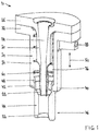
- the device 10 according to the invention for filling infusion bags is shown in FIG Fig. 1 and 2 shown.
- the device 10 has a filling needle 20.
- the lower end 22 of the filling needle 20 can be brought into contact with a corresponding attachment of an infusion bag - in particular with the filling tube of the infusion bag - so that the liquid to be filled through the interior 24 of the filling needle into the infusion bag can be filled.
- the filling needle 20 has a radially projecting connection flange 26. Via the connection flange 26, the filling needle 20 can be attached to a filling device, not shown here, in particular to a filling head.
- the fastening can preferably take place via one or more screws.
- a base holder 30 with its radially projecting connection flange 32 is fastened to the connection flange 26 of the filling needle 20.
- the basic holder 30 has a pipe socket 34 which extends around the filling needle 20 on the outside.
- a circumferential gap 36 is present between the pipe socket 34 of the base holder 30 and the filling needle 20.
- the filling needle 20 has an approximately circular cross-section
- the pipe socket 34 of the basic holder 30 also has a circular cross-section.
- the circumferential intermediate space 36 is of annular design.
- the cross-sectional shape of the filling needle 20, in particular of the lower end 22 of the filling needle 20 can be freely selected in the device according to the invention.
- the lower end 22 of the filling needle 20 can be adapted to different connections of an infusion bag and to different cross-sectional shapes of the filling tubes of an infusion bag.
- the shape of the filling needle 20 can also be adapted to the shape of the pipe socket 34 of the basic holder 30.
- the pipe socket 34 can therefore also have a rectangular, square or oval cross section, for example.
- a gas connection 38 is present on the upper edge region of the pipe socket 34.
- the gas connection 40 is provided directly below the connection flange 32.
- the circumferential space 36 between the pipe socket 34 and the filling needle 20 can be flooded with an inert gas, in particular with nitrogen.
- the individual gas connections 38 should each be present on the upper edge area of the pipe socket 34 of the base holder so that the circumferential gap 36 can be flooded with inert gas over its entire longitudinal alignment and no residues of the ambient air remain in the upper edge areas of the circumferential gap 36.
- the lower end 40 of the pipe socket 34 of the basic holder 30 is located a little above the lower end 22 of the filling needle 20.
- the filling needle 20 thus projects a little beyond the basic holder 30.
- the lower end 40 of the basic holder 30 has an inwardly cantilevered circumferential shoulder formation 42.
- On this circumferential shoulder formation 42 is a movable nozzle 44 in its Fig 1 shown rest position 46 with a circumferential cantilever nose 48.
- the movable nozzle 44 extends the circumferential space 36 downwards. In this case, the movable nozzle 44 protrudes downward in its rest position 46 beyond the lower end 22 of the filling needle 20.
- the filling needle 20 can be adjusted together with the base holder 30 and the movable nozzle 44 in its longitudinal direction 50 and thus be designed to be adjustable in height. In this way, the filling needle 20 with the base holder 30 and the movable nozzle 44 can be lowered continuously in the longitudinal direction 50 in the present example.
- the filling tube of the infusion bag remaining above the clamp is flooded with inert gas.
- the lower end 52 of the movable nozzle 44 comes into contact with two centering jaws 54, 56 (see FIG Fig. 2 ).
- the two centering jaws 54, 56 thus serve as a stop for the movable nozzle 44 and prevent the movable nozzle 44 from being lowered further.
- the centering jaws 54, 56 move the movable nozzle 44 upwards from its rest position 46, so that when the device 10 is lowered further, the lower end 22 of the filling needle 20 is present below the lower end 52 of the movable nozzle 44.
- the circumferential cantilever nose 48 of the movable nozzle 44 slides along the inside 58 of the pipe socket 34.
- a compression spring 60 is present in the circumferential gap 36.
- the compression spring 60 runs along the inside 58 of the pipe socket and presses the movable nozzle 44 into its rest position 46.
- the compression spring is tensioned, so that after the deflecting force has been removed, the compression spring the pushes the movable nozzle back into its rest position.
- the filling hose could be flooded in particular during the waiting positions.
Landscapes
- Engineering & Computer Science (AREA)
- Health & Medical Sciences (AREA)
- Mechanical Engineering (AREA)
- Veterinary Medicine (AREA)
- Heart & Thoracic Surgery (AREA)
- Dispersion Chemistry (AREA)
- Chemical & Material Sciences (AREA)
- Life Sciences & Earth Sciences (AREA)
- Animal Behavior & Ethology (AREA)
- General Health & Medical Sciences (AREA)
- Public Health (AREA)
- Biomedical Technology (AREA)
- Hematology (AREA)
- Physics & Mathematics (AREA)
- Fluid Mechanics (AREA)
- Pharmacology & Pharmacy (AREA)
- Anesthesiology (AREA)
- Pulmonology (AREA)
- Supply Of Fluid Materials To The Packaging Location (AREA)
- Vacuum Packaging (AREA)
- Basic Packing Technique (AREA)
Abstract
Description
- Die Erfindung betrifft eine Vorrichtung zum Befüllen von Infusionsbeuteln, insbesondere zum Befüllen von Infusionsbeuteln mit einer Flüssigkeit. Bei den Infusionsbeuteln kann es sich um Beutel mit lediglich einer Kammer handeln, aber auch um Mehrkammerbeutel. Mehrkammerbeutel können beispielsweise auch ein Pulver und eine Liquidkammer umfassen.
- Die Befüllung von Infusionsbeuteln muss in der Regel unter besonderen Bedingungen ("low bio burden" genannt) erfolgen, da der in den Infusionsbeuteln enthaltene Inhalt einem Patienten zugeführt wird und daher nicht kontaminiert werden darf. Bei kritischen Inhaltsstoffen, insbesondere bei Krebsmedikamenten oder auch bei Infusionen zur parenteralen Ernährung, kann eine Abfüllung der Infusionsbeutel unter Inertgas notwendig sein, da die abzufüllende Flüssigkeit nicht mit Luft-Sauerstoff in Kontakt kommen darf. Dabei wird in der Regel Stickstoff als Inertgas verwendet.
- Eine Abfüllung von Flüssigkeiten unter Inertgas-Bedingungen kann beispielsweise durch eine Dachbegasung erfolgen. In diesem Fall wird die Vorrichtung zum Befüllen der Infusionsbeutel in einem konstanten Strom aus Inertgas platziert. Bei dieser Methode werden jedoch große Mengen an Stickstoff verbraucht, so dass erhebliche Kosten entstehen. Darüber hinaus kommt es zu einer sicherheitstechnischen Problematik, da die großen Mengen an Stickstoff häufig bauartbedingt unkontrolliert abfließen. Darüber hinaus wird der kritische Beutelbereich abgeschattet, so dass gegebenenfalls kein optimaler laminarer Luftstrom im kritischen Bereich der Füllschläuche erreicht werden kann.
- Alternativ zu der Dachbegasung kann für die Befüllung von Infusionsbeuteln unter Inertgas-Bedingungen ein spezieller Füllkopf verwendet werden, bei dem mehrere Medien durch die Füllnadel geleitet werden können. Auf diese Weise kann eine Nachbegasung mit Stickstoff möglich sein. Auch eine Evakuierung der Füllschläuche vor dem eigentlichen Befüllen wäre auf diese Weise möglich. Bei einem solchen Füllkopf für mehrere Medien gestaltet sich die Reinigung des Füllkopfes jedoch sehr schwierig. Insbesondere durch die Möglichkeit des Einzugs von Rest-Flüssigkeit in den Vakuumkreis ist eine intensive Reinigung des Füllkopfes jedoch unerlässlich. Die Nutzung der Füllnadel für Vakuum und/ oder Stickstoffbegasung neben der eigentlichen Verwendung zur Befüllung der Infusionsbeutel mit einer Flüssigkeit erfordert die vollständige Entleerung der Füllnadel vor dem Wechsel der Anwendung. Unter Berücksichtigung der vorgesehenen Füllmedien ist dies unerwünscht und technisch sehr aufwendig. Die Restmengen der Füllmedien müssen separat gesammelt und entsorgt werden, da keine Entsorgung über das Abwasser möglich ist.
- Ausgehend von diesem vorbekannten Stand der Technik liegt der Erfindung die Aufgabe zugrunde, eine verbesserte Vorrichtung zum Befüllen von Infusionsbeuteln anzugeben, bei der eine Befüllung unter Inertgas-Bedingungen prozesssicher möglich ist.
- Die erfindungsgemäße Vorrichtung zum Befüllen von Infusionsbeuteln ist durch die Merkmale des Hauptanspruchs 1 gegeben. Sinnvolle Weiterbildungen der Erfindung sind Gegenstand von sich an diesen Anspruch anschließenden weiteren Ansprüchen.
- Die erfindungsgemäße Vorrichtung zum Befüllen eines Infusionsbeutels besitzt eine Füllnadel und einen Grundhalter, der so um die Füllnadel herum verläuft, dass zwischen der Füllnadel und dem Grundhalter ein umlaufender Zwischenraum vorhanden ist. Darüber hinaus ist zumindest ein Gasanschluss für Inertgas vorhanden, durch den Inertgas in den umlaufenden Zwischenraum zwischen der Füllnadel und dem Grundhalter geleitet werden kann. Am unteren Ende des Grundhalters ist eine bewegliche Düse vorhanden, die längsverschieblich gelagert ist und in ihrer Ruhestellung über das untere Ende der Füllnadel hinausragt.
- Die Füllnadel selbst wird erfindungsgemäß somit lediglich für die Befüllung der Infusionsbeutel mit der zu befüllenden Flüssigkeit verwendet. Die verwendeten Medien (Inertgas beziehungsweise zu befüllende Flüssigkeit) werden daher durch unterschiedliche Kanäle geleitet, so dass keine Vermischung der Medien stattfindet. Dies führt zu einer vergleichsweise einfachen Maschinenkonstruktion. Die erfindungsgemäße Ausgestaltung der Vorrichtung zum Befüllen von Infusionsbeuteln ermöglicht daher eine effektive und prozesssichere Reinigung der Vorrichtung, insbesondere der Füllnadel.
- Durch die Verwendung der erfindungsgemäßen Vorrichtung können Einkammerbeutel und Mehrkammerbeutel mit einem deutlich reduzierten Rest-Sauerstoffgehalt im Headspace hergestellt werden. Dabei können deutliche reduzierte Zykluszeiten realisiert werden, so dass ein sicherer und wirtschaftlicher Betrieb der erfindungsgemäßen Vorrichtung möglich ist.
- Die voreilende bewegliche Düse kann insbesondere federbelastet sein und mittels einer Druckfeder längsverschieblich gelagert sein. Eine solche Ausführungsform ist einfach und wirtschaftlich umsetzbar und kann im Bedarfsfall unkompliziert ausgetauscht werden.
- Die Form der Füllnadel selbst, insbesondere des unteren Endes der Füllnadel, die in den Infusionsbeutel eingeführt wird, wird durch die erfindungsgemäße Vorrichtung nicht eingeschränkt. Insofern sind nach wie vor unterschiedliche äußere Geometrien der Füllnadel möglich, so dass beispielsweise eine Anpassung der Füllnadel an die Form des Anschlusses der Infusionsbeutel möglich ist.
- In der Regel wird der zu befüllende Infusionsbeutel an einer vorgelagerten Station mit Inertgas, insbesondere mit Stickstoff gespült werden. Der gespülte Infusionsbeutel wird anschließend leergedrückt und der Füllschlauch des Infusionsbeutels abgeklemmt. Oberhalb der Abklemmung bleibt ein Stück Füllschlauch stehen. Dieses Stück Füllschlauch kann in Kontakt mit der Umgebungsluft kommen und dadurch für unzulässig hohe Sauerstoffwerte bei der Abfüllung der Infusionsbeutel sorgen.
- Bei der Befüllung eines Infusionsbeutels kann zunächst lediglich das Inertgas durch den umlaufenden Zwischenraum und die bewegliche Düse geleitet werden. Auf diese Weise kann Inertgas in den oberhalb der Abklemmung verbleibenden Füllschlauch des Infusionsbeutels geleitet werden, um die Umgebungsluft aus dem Füllschlauch zu verdrängen. Anschließend kann die bewegliche Düse ein Stück weit nach oben zurückgeschoben werden. Vorzugsweise kann die bewegliche Düse dabei so weit nach oben zurückgeschoben werden, dass diese oberhalb des unteren Endes der Füllnadel vorhanden ist. Dadurch kann die Füllnadel zur Befüllung des Infusionsbeutels mit der zu befüllenden Flüssigkeit in direkten Kontakt mit dem Füllschlauch des Infusionsbeutels gebracht werden, so dass kein Kontakt der zu befüllenden Flüssigkeit mit Umgebungsluft möglich sein sollte.
- Um die bewegliche Düse aus ihrer Ruhestellung nach oben zu verschieben, kann in einer ersten Ausführungsform ein Anschlagelement vorhanden sein. Sofern die Vorrichtung höhenverstellbar ausgebildet ist, kann bei einem Absenken der Vorrichtung zunächst ein Kontakt mit dem Anschlagelement erfolgen, durch das die bewegliche Düse beim weiteren Absenken der Vorrichtung entsprechend nach oben verschoben werden kann. In einer zweiten Ausführungsform kann die bewegliche Düse durch einen motorischen oder pneumatischen Antrieb aus ihrer Ruhestellung nach oben verschoben werden. Eine solche Ausbildung wäre unabhängig von einer möglichen Höhenverstellbarkeit der Vorrichtung.
- Die Füllnadel kann einen radial auskragenden Anschlussflansch aufweisen. Über diesen Anschlussflansch kann die Füllnadel an einer Befüllvorrichtung angeschlossen werden. Auch der Grundhalter kann einen radial auskragenden Anschlussflansch aufweisen, so dass eine Befestigung des Grundhalters an der Füllnadel über die jeweiligen Anschlussflansche möglich ist.
- Grundsätzlich kann ein einzelner Gasanschluss für Inertgas ausreichend sein, um den umlaufenden Zwischenraum mit Inertgas zu befüllen und ausreichend Inertgas über die bewegliche Düse auszuströmen. Vorzugsweise können jedoch mehrere, insbesondere drei Gasanschlüsse vorhanden sein, die umfangmäßig verteilt angeordnet sind. Dies ermöglicht eine gleichmäßige Verteilung des Inertgases innerhalb des umlaufenden Zwischenraums und gewährleistet darüber hinaus, dass die Flutung des Füllschlauchs oberhalb der Abklemmung mit Inertgas rasch erfolgt.
- Weitere Vorteile und Merkmale der Erfindung sind den in den Ansprüchen ferner angegebenen Merkmalen sowie dem nachstehenden Ausführungsbeispiel zu entnehmen.
- Die Erfindung wird im Folgenden anhand des in der Zeichnung dargestellten Ausführungsbeispiels näher beschrieben und erläutert. Es zeigen:
- Fig. 1
- einen Querschnitt durch die erfindungsgemäße Vorrichtung zum Befüllen von Infusionsbeuteln in der Ruhestellung der beweglichen Düse, und
- Fig. 2
- einen Querschnitt gemäß
Fig 1 , bei dem die bewegliche Düse durch Zentrierbacken nach oben verschoben wurde. - Die erfindungsgemäße Vorrichtung 10 zum Befüllen von Infusionsbeuteln ist in
Fig. 1 und2 dargestellt. Die Vorrichtung 10 besitzt eine Füllnadel 20. Das untere Ende 22 der Füllnadel 20 kann mit einem entsprechenden Ansatz eines Infusionsbeutels - insbesondere mit dem Füllschlauch des Infusionsbeutels - in Kontakt gebracht werden, so dass die zu befüllende Flüssigkeit durch den Innenraum 24 der Füllnadel in den Infusionsbeutel eingefüllt werden kann. Die Füllnadel 20 besitzt an ihrem oberen Ende einen radial auskragenden Anschlussflansch 26. Über den Anschlussflansch 26 kann die Füllnadel 20 an einer hier nicht dargestellten Befüllvorrichtung, insbesondere an einem Füllkopf, befestigt werden. Die Befestigung kann dabei vorzugsweise über eine oder mehrere Schrauben erfolgen. - An dem Anschlussflansch 26 der Füllnadel 20 ist ein Grundhalter 30 mit seinem radial auskragenden Anschlussflansch 32 befestigt. Der Grundhalter 30 besitzt einen Rohrstutzen 34, der außen um die Füllnadel 20 herum verläuft. Zwischen dem Rohrstutzen 34 des Grundhalters 30 und der Füllnadel 20 ist ein umlaufender Zwischenraum 36 vorhanden.
- Im vorliegenden Beispielsfall weist die Füllnadel 20 einen etwa kreisförmigen Querschnitt auf, auch der Rohrstutzen 34 des Grundhalters 30 weist einen kreisförmigen Querschnitt auf. Entsprechend ist der umlaufende Zwischenraum 36 im vorliegenden Beispielsfall ringförmig ausgebildet. Grundsätzlich ist die Querschnittsform der Füllnadel 20, insbesondere des unteren Endes 22 der Füllnadel 20 bei der erfindungsgemäßen Vorrichtung frei wählbar. Dadurch kann eine Anpassung des unteren Endes 22 der Füllnadel 20 an unterschiedliche Anschlüsse eines Infusionsbeutels und an unterschiedliche Querschnittsformen der Füllschläuche eines Infusionsbeutels erfolgen. Abhängig von der gewählten Form der Füllnadel 20 kann auch die Form des Rohrstutzens 34 des Grundhalters 30 angepasst werden. Der Rohrstutzen 34 kann also beispielsweise auch einen rechteckigen, eine quadratischen oder einen ovalen Querschnitt aufweisen.
- An dem oberen Randbereich des Rohrstutzens 34 ist im vorliegenden Beispielsfall ein Gasanschluss 38 vorhanden. Der Gasanschluss 40 ist unmittelbar unterhalb des Anschlussflansches 32 vorhanden. Durch den Gasanschluss 38 kann der umlaufende Zwischenraum 36 zwischen dem Rohrstutzen 34 und der Füllnadel 20 mit einem Inertgas, insbesondere mit Stickstoff, geflutet werden. Neben dem Gasanschluss 38 können weitere Gasanschlüsse vorhanden sein, die umfangmäßig verteilt angeordnet sein sollten, so dass eine gleichmäßig Flutung des umlaufenden Zwischenraums 36 mit Inertgas möglich ist. Darüber hinaus sollten die einzelnen Gasanschlüsse 38 jeweils am oberen Randbereich des Rohrstutzens 34 des Grundhalters vorhanden sein, damit der umlaufende Zwischenraum 36 möglichst über seine gesamte Längsausrichtung mit Inertgas geflutet werden kann und keine Reste der Umgebungsluft in den oberen Randbereichen des umlaufenden Zwischenraums 36 verbleiben.
- Das untere Ende 40 des Rohrstutzens 34 des Grundhalters 30 befindet sich ein Stück oberhalb des unteren Endes 22 der Füllnadel 20. Die Füllnadel 20 steht somit ein Stück weit über den Grundhalter 30 über. Im vorliegenden Beispielsfall weist das untere Ende 40 des Grundhalters 30 eine nach innen kragende umlaufende Schulterausbildung 42 auf. An dieser umlaufenden Schulterausbildung 42 liegt eine bewegliche Düse 44 in ihrer in
Fig 1 dargestellten Ruhestellung 46 mit einer umlaufenden Kragnase 48 auf. Die bewegliche Düse 44 verlängert den umlaufenden Zwischenraum 36 nach unten hin. Dabei ragt die bewegliche Düse 44 in ihrer Ruhestellung 46 nach unten über das untere Ende 22 der Füllnadel 20 hinaus. - Die Füllnadel 20 kann zusammen mit dem Grundhalter 30 und der beweglichen Düse 44 in ihrer Längsrichtung 50 verstellt werden und somit höhenverstellbar ausgebildet sein. Auf diese Weise kann die Füllnadel 20 mit dem Grundhalter 30 und der beweglichen Düse 44 im vorliegenden Beispielsfall kontinuierlich in Längsrichtung 50 abgesenkt werden. Während dieses Absenkens der Füllnadel 20 erfolgt gleichzeitig eine Flutung des oberhalb der Abklemmung verbleibenden Füllschlauchs des Infusionsbeutels mit Inertgas. Während des Absenkens kommt es zu einem Kontakt des unteren Endes 52 der beweglichen Düse 44 mit zwei Zentrierbacken 54, 56 (siehe
Fig. 2 ). Die beiden Zentrierbacken 54, 56 dienen somit als Anschlag für die bewegliche Düse 44 und verhindern, dass die bewegliche Düse 44 weiter abgesenkt werden kann. Durch die Zentrierbacken 54, 56 wird die bewegliche Düse 44 aus ihrer Ruhestellung 46 nach oben verschoben, so dass beim weiteren Absenken der Vorrichtung 10 das untere Ende 22 der Füllnadel 20 unterhalb des unteren Endes 52 der beweglichen Düse 44 vorhanden ist. Dabei gleitet die umlaufende Kragnase 48 der beweglichen Düse 44 an der Innenseite 58 des Rohrstutzens 34 entlang. Sobald das untere Ende 22 der Füllnadel 20 so weit abgesenkt wurde, dass ein Kontakt mit dem Füllschlauch des Infusionsbeutels besteht, kann der eigentliche Befüllvorgang gestartet werden. - In dem umlaufenden Zwischenraum 36 ist im vorliegenden Beispielsfall eine Druckfeder 60 vorhanden. Die Druckfeder 60 verläuft entlang der Innenseite 58 des Rohrstutzens und drückt die bewegliche Düse 44 in ihre Ruhestellung 46. Bei einer Auslenkung der beweglichen Düse 44 aus ihrer Ruhestellung 46 heraus, wird die Druckfeder gespannt, so dass nach dem Entfernen der auslenkenden Kraft die Druckfeder die bewegliche Düse wieder in ihre Ruhestellung drückt.
- Statt einer kontinuierlichen Absenkung der Vorrichtung wäre es auch möglich, während des Absenkens der Vorrichtung eine oder mehrere Wartepositionen vorzusehen. In diesem Fall könnte die Flutung des Füllschlauchs insbesondere während der Wartepositionen erfolgen.
Claims (10)
- Vorrichtung (10) zum Befüllen eines Infusionsbeutels mit einer Flüssigkeit- mit einer Füllnadel (20),- mit einem Grundhalter (30), der so um die Füllnadel (20) herum verläuft, dass zwischen der Füllnadel (20) und dem Grundhalter (30) ein umlaufender Zwischenraum (36) vorhanden ist,- mit zumindest einem Gasanschluss (38) für Inertgas, durch den Inertgas in den umlaufenden Zwischenraum (36) zwischen Füllnadel (20) und Grundhalter (30) leitbar ist,- mit einer beweglichen Düse (44), die längsverschieblich an dem unteren Ende (40) des Grundhalters (30) befestigt ist,- wobei die bewegliche Düse (44) in ihrer Ruhestellung (46) über das untere Ende (22) der Füllnadel (20) hinausragt.
- Vorrichtung nach Anspruch 1,- dadurch gekennzeichnet, dass- die bewegliche Düse (44) mittels einer Druckfeder (60) längsverschieblich gelagert ist.
- Vorrichtung nach Anspruch 1 oder 2,- dadurch gekennzeichnet, dass- die bewegliche Düse (44) in ihrer zurückgeschobenen Position oberhalb des unteren Endes (22) der Füllnadel (20) vorhanden ist.
- Vorrichtung nach einem der Ansprüche 1 bis 3,- dadurch gekennzeichnet, dass- ein Anschlagelement (54, 56) vorhanden ist, durch das die bewegliche Düse (44) aus ihrer Ruhestellung (46) nach oben verschiebbar ist.
- Vorrichtung nach einem der Ansprüche 1 bis 3,- dadurch gekennzeichnet, dass- die bewegliche Düse (44) durch einen motorischen oder pneumatischen Antrieb aus ihrer Ruhestellung (46) nach oben verschiebbar ist.
- Vorrichtung nach einem der vorstehenden Ansprüche,- dadurch gekennzeichnet, dass- die Füllnadel (20) zusammen mit dem Grundhalter (30) und der beweglichen Düse (44) höhenverstellbar ausgebildet ist.
- Vorrichtung nach einem der vorstehenden Ansprüche,- dadurch gekennzeichnet, dass- die Füllnadel (20) einen radial auskragenden Anschlussflansch (26) aufweist,- die Füllnadel (20) mit ihrem Anschlussflansch (26) an einer Befüllvorrichtung anschließbar ist.
- Vorrichtung nach Anspruch 7,- dadurch gekennzeichnet, dass- der Grundhalter (30) einen radial auskragenden Anschlussflansch (32) aufweist,- der Anschlussflansch (32) des Grundhalters (30) an dem Anschlussflansch (26) der Füllnadel (20) befestigbar ist.
- Vorrichtung nach einem der vorstehenden Ansprüche,- dadurch gekennzeichnet, dass- zumindest drei Gasanschlüsse (38) für Inertgas vorhanden sind, durch die Inertgas in den umlaufenden Zwischenraum (36) zwischen Füllnadel (20) und Grundhalter (30) leitbar ist.
- Vorrichtung nach einem der vorstehenden Ansprüche,- dadurch gekennzeichnet, dass- der umlaufende Zwischenraum (36) zwischen Füllnadel (20) und Grundhalter (30) ringförmig ausgebildet ist.
Priority Applications (1)
| Application Number | Priority Date | Filing Date | Title |
|---|---|---|---|
| EP20173245.0A EP3907142B1 (de) | 2020-05-06 | 2020-05-06 | Vorrichtung zum befüllen von infusionsbeuteln |
Applications Claiming Priority (1)
| Application Number | Priority Date | Filing Date | Title |
|---|---|---|---|
| EP20173245.0A EP3907142B1 (de) | 2020-05-06 | 2020-05-06 | Vorrichtung zum befüllen von infusionsbeuteln |
Publications (2)
| Publication Number | Publication Date |
|---|---|
| EP3907142A1 true EP3907142A1 (de) | 2021-11-10 |
| EP3907142B1 EP3907142B1 (de) | 2025-04-30 |
Family
ID=70975669
Family Applications (1)
| Application Number | Title | Priority Date | Filing Date |
|---|---|---|---|
| EP20173245.0A Active EP3907142B1 (de) | 2020-05-06 | 2020-05-06 | Vorrichtung zum befüllen von infusionsbeuteln |
Country Status (1)
| Country | Link |
|---|---|
| EP (1) | EP3907142B1 (de) |
Citations (5)
| Publication number | Priority date | Publication date | Assignee | Title |
|---|---|---|---|---|
| US3299603A (en) * | 1962-03-12 | 1967-01-24 | Continental Can Co | Method of filling pouches |
| EP1411023A1 (de) * | 2002-10-17 | 2004-04-21 | Shibuya Kogyo Co., Ltd | Füllventil |
| EP1860057A1 (de) * | 2006-05-24 | 2007-11-28 | Sidel Holdings & Technology S.A. | Ventileinheit für Füllmaschinen mit Füllhöheprobe in isoliertem Rohr |
| WO2012061359A1 (en) * | 2010-11-01 | 2012-05-10 | Ge Healthcare Limited | Pierce and fill device |
| DE102015106125B3 (de) * | 2015-04-21 | 2016-09-08 | Khs Gmbh | Füllelementanordnung sowie Füllmaschine |
-
2020
- 2020-05-06 EP EP20173245.0A patent/EP3907142B1/de active Active
Patent Citations (5)
| Publication number | Priority date | Publication date | Assignee | Title |
|---|---|---|---|---|
| US3299603A (en) * | 1962-03-12 | 1967-01-24 | Continental Can Co | Method of filling pouches |
| EP1411023A1 (de) * | 2002-10-17 | 2004-04-21 | Shibuya Kogyo Co., Ltd | Füllventil |
| EP1860057A1 (de) * | 2006-05-24 | 2007-11-28 | Sidel Holdings & Technology S.A. | Ventileinheit für Füllmaschinen mit Füllhöheprobe in isoliertem Rohr |
| WO2012061359A1 (en) * | 2010-11-01 | 2012-05-10 | Ge Healthcare Limited | Pierce and fill device |
| DE102015106125B3 (de) * | 2015-04-21 | 2016-09-08 | Khs Gmbh | Füllelementanordnung sowie Füllmaschine |
Also Published As
| Publication number | Publication date |
|---|---|
| EP3907142B1 (de) | 2025-04-30 |
Similar Documents
| Publication | Publication Date | Title |
|---|---|---|
| EP2788275B1 (de) | Füllelement mit einem trinox-rohr | |
| WO2005019090A1 (de) | Gegendruck-füllvorrichtung und verfahren zum gegendruckfüllen | |
| DE102015116532A1 (de) | Verfahren sowie Behandlungsstation und Behandlungskopf zur Behandlung der Innenräume von KEGs sowie Dichtung zur Verwendung bei einer derartigen Behandlungsstation | |
| DE102013108295B4 (de) | Reinigungsvorrichtung | |
| EP3067126A1 (de) | Vorrichtung zum spülen eines behälters mit einem spülmedium | |
| WO2013050968A1 (de) | Verfahren zur kontaminationsvermeidenden entleerung beziehungsweise befüllung eines behälters | |
| DE2034911B2 (de) | Vorrichtung zur Behandlung von insbesondere zellförmigen Materialien mit Temperatur- und Druckstollen durch Zünden eines Arbeitsmittels | |
| EP4251879B1 (de) | Verfahren zum entleeren von viskosem material aus einer beidseitig offenen kartusche sowie hierfür geeignete entleer-vorrichtung | |
| EP3907142B1 (de) | Vorrichtung zum befüllen von infusionsbeuteln | |
| DE102011086278A1 (de) | Entleerverfahren und Entleervorrichtung für ein kontaminationsfreies Entleeren eines zumindest teilweise flexiblen Gebindes | |
| DE19616484A1 (de) | Verfahren zum Kaltbiegen von hohlen Werkstücken | |
| WO1993009056A1 (de) | Vorrichtung zum reinigen und entleeren von getränkeflüssigkeitsleitungen in zapfanlangen | |
| DE19932519C2 (de) | Vorrichtung zum Entleeren von Spraydosen | |
| EP2615449B1 (de) | Wechselarmatur für ein behältnis und verwendung einer wechselarmatur | |
| WO2018137811A1 (de) | Füllsystem zum füllen von behältern mit einem flüssigen füllgut | |
| DE2648330C2 (de) | Vorrichtung zur Entnahme einer Probe aus einer abgepumpten begrenzten Menge einer inhomogenen Flüssigkeit | |
| EP3717397B1 (de) | Verschliessvorrichtung zum begasen und verschliessen von behältern, die eine einfüllöffnung aufweisen | |
| DE3618981C2 (de) | ||
| WO1997038904A1 (de) | Verfahren und vorrichtung zur vermeidung von produktestaub- oder produktegasaustritt bei abfüllung mit feststoff- oder flüssigkeitsdosiersystemen | |
| DE2539656A1 (de) | Einfuellvorrichtung und einfuellverfahren fuer viskose stoffe | |
| EP3127826B1 (de) | Düse zum aufblasen eines spout-folienbeutels und verfahren zum aufblasen eines spout-folienbeutels | |
| DE102023124506B3 (de) | Prüfvorrichtung und Verfahren sowie Prüfstation zur Dichtigkeitsprüfung von offenen, nicht befüllten Dosen | |
| DE3914992C2 (de) | Vorrichtung zum Verbinden der Enden von mit einer Drahtumflechtung versehenen Ringwellenschläuchen | |
| EP4339111A1 (de) | Vorrichtung und verfahren zum befüllen von beuteln | |
| DE3543823C2 (de) | Vorrichtung zum Füllen von Ampullen mit einer Gas- oder Flüssigkeitsprobe |
Legal Events
| Date | Code | Title | Description |
|---|---|---|---|
| PUAI | Public reference made under article 153(3) epc to a published international application that has entered the european phase |
Free format text: ORIGINAL CODE: 0009012 |
|
| STAA | Information on the status of an ep patent application or granted ep patent |
Free format text: STATUS: THE APPLICATION HAS BEEN PUBLISHED |
|
| AK | Designated contracting states |
Kind code of ref document: A1 Designated state(s): AL AT BE BG CH CY CZ DE DK EE ES FI FR GB GR HR HU IE IS IT LI LT LU LV MC MK MT NL NO PL PT RO RS SE SI SK SM TR |
|
| B565 | Issuance of search results under rule 164(2) epc |
Effective date: 20201030 |
|
| STAA | Information on the status of an ep patent application or granted ep patent |
Free format text: STATUS: REQUEST FOR EXAMINATION WAS MADE |
|
| 17P | Request for examination filed |
Effective date: 20220224 |
|
| RBV | Designated contracting states (corrected) |
Designated state(s): AL AT BE BG CH CY CZ DE DK EE ES FI FR GB GR HR HU IE IS IT LI LT LU LV MC MK MT NL NO PL PT RO RS SE SI SK SM TR |
|
| GRAP | Despatch of communication of intention to grant a patent |
Free format text: ORIGINAL CODE: EPIDOSNIGR1 |
|
| STAA | Information on the status of an ep patent application or granted ep patent |
Free format text: STATUS: GRANT OF PATENT IS INTENDED |
|
| INTG | Intention to grant announced |
Effective date: 20241220 |
|
| GRAS | Grant fee paid |
Free format text: ORIGINAL CODE: EPIDOSNIGR3 |
|
| GRAA | (expected) grant |
Free format text: ORIGINAL CODE: 0009210 |
|
| STAA | Information on the status of an ep patent application or granted ep patent |
Free format text: STATUS: THE PATENT HAS BEEN GRANTED |
|
| AK | Designated contracting states |
Kind code of ref document: B1 Designated state(s): AL AT BE BG CH CY CZ DE DK EE ES FI FR GB GR HR HU IE IS IT LI LT LU LV MC MK MT NL NO PL PT RO RS SE SI SK SM TR |
|
| REG | Reference to a national code |
Ref country code: CH Ref legal event code: EP Ref country code: GB Ref legal event code: FG4D Free format text: NOT ENGLISH |
|
| REG | Reference to a national code |
Ref country code: IE Ref legal event code: FG4D Free format text: LANGUAGE OF EP DOCUMENT: GERMAN |
|
| REG | Reference to a national code |
Ref country code: DE Ref legal event code: R096 Ref document number: 502020010927 Country of ref document: DE |
|
| REG | Reference to a national code |
Ref country code: NL Ref legal event code: MP Effective date: 20250430 |
|
| PG25 | Lapsed in a contracting state [announced via postgrant information from national office to epo] |
Ref country code: FI Free format text: LAPSE BECAUSE OF FAILURE TO SUBMIT A TRANSLATION OF THE DESCRIPTION OR TO PAY THE FEE WITHIN THE PRESCRIBED TIME-LIMIT Effective date: 20250430 Ref country code: ES Free format text: LAPSE BECAUSE OF FAILURE TO SUBMIT A TRANSLATION OF THE DESCRIPTION OR TO PAY THE FEE WITHIN THE PRESCRIBED TIME-LIMIT Effective date: 20250430 Ref country code: PT Free format text: LAPSE BECAUSE OF FAILURE TO SUBMIT A TRANSLATION OF THE DESCRIPTION OR TO PAY THE FEE WITHIN THE PRESCRIBED TIME-LIMIT Effective date: 20250901 |
|
| REG | Reference to a national code |
Ref country code: LT Ref legal event code: MG9D |
|
| PG25 | Lapsed in a contracting state [announced via postgrant information from national office to epo] |
Ref country code: NO Free format text: LAPSE BECAUSE OF FAILURE TO SUBMIT A TRANSLATION OF THE DESCRIPTION OR TO PAY THE FEE WITHIN THE PRESCRIBED TIME-LIMIT Effective date: 20250730 Ref country code: GR Free format text: LAPSE BECAUSE OF FAILURE TO SUBMIT A TRANSLATION OF THE DESCRIPTION OR TO PAY THE FEE WITHIN THE PRESCRIBED TIME-LIMIT Effective date: 20250731 |
|
| PG25 | Lapsed in a contracting state [announced via postgrant information from national office to epo] |
Ref country code: PL Free format text: LAPSE BECAUSE OF FAILURE TO SUBMIT A TRANSLATION OF THE DESCRIPTION OR TO PAY THE FEE WITHIN THE PRESCRIBED TIME-LIMIT Effective date: 20250430 Ref country code: NL Free format text: LAPSE BECAUSE OF FAILURE TO SUBMIT A TRANSLATION OF THE DESCRIPTION OR TO PAY THE FEE WITHIN THE PRESCRIBED TIME-LIMIT Effective date: 20250430 |
|
| PG25 | Lapsed in a contracting state [announced via postgrant information from national office to epo] |
Ref country code: BG Free format text: LAPSE BECAUSE OF FAILURE TO SUBMIT A TRANSLATION OF THE DESCRIPTION OR TO PAY THE FEE WITHIN THE PRESCRIBED TIME-LIMIT Effective date: 20250430 |
|
| PG25 | Lapsed in a contracting state [announced via postgrant information from national office to epo] |
Ref country code: HR Free format text: LAPSE BECAUSE OF FAILURE TO SUBMIT A TRANSLATION OF THE DESCRIPTION OR TO PAY THE FEE WITHIN THE PRESCRIBED TIME-LIMIT Effective date: 20250430 |
|
| PG25 | Lapsed in a contracting state [announced via postgrant information from national office to epo] |
Ref country code: RS Free format text: LAPSE BECAUSE OF FAILURE TO SUBMIT A TRANSLATION OF THE DESCRIPTION OR TO PAY THE FEE WITHIN THE PRESCRIBED TIME-LIMIT Effective date: 20250731 |
|
| PG25 | Lapsed in a contracting state [announced via postgrant information from national office to epo] |
Ref country code: IS Free format text: LAPSE BECAUSE OF FAILURE TO SUBMIT A TRANSLATION OF THE DESCRIPTION OR TO PAY THE FEE WITHIN THE PRESCRIBED TIME-LIMIT Effective date: 20250830 |
|
| PG25 | Lapsed in a contracting state [announced via postgrant information from national office to epo] |
Ref country code: LV Free format text: LAPSE BECAUSE OF FAILURE TO SUBMIT A TRANSLATION OF THE DESCRIPTION OR TO PAY THE FEE WITHIN THE PRESCRIBED TIME-LIMIT Effective date: 20250430 |
|
| REG | Reference to a national code |
Ref country code: CH Ref legal event code: H13 Free format text: ST27 STATUS EVENT CODE: U-0-0-H10-H13 (AS PROVIDED BY THE NATIONAL OFFICE) Effective date: 20251223 |
|
| PG25 | Lapsed in a contracting state [announced via postgrant information from national office to epo] |
Ref country code: SM Free format text: LAPSE BECAUSE OF FAILURE TO SUBMIT A TRANSLATION OF THE DESCRIPTION OR TO PAY THE FEE WITHIN THE PRESCRIBED TIME-LIMIT Effective date: 20250430 Ref country code: DK Free format text: LAPSE BECAUSE OF FAILURE TO SUBMIT A TRANSLATION OF THE DESCRIPTION OR TO PAY THE FEE WITHIN THE PRESCRIBED TIME-LIMIT Effective date: 20250430 |
|
| PG25 | Lapsed in a contracting state [announced via postgrant information from national office to epo] |
Ref country code: LU Free format text: LAPSE BECAUSE OF NON-PAYMENT OF DUE FEES Effective date: 20250506 |
|
| PG25 | Lapsed in a contracting state [announced via postgrant information from national office to epo] |
Ref country code: CH Free format text: LAPSE BECAUSE OF NON-PAYMENT OF DUE FEES Effective date: 20250531 |
|
| PG25 | Lapsed in a contracting state [announced via postgrant information from national office to epo] |
Ref country code: CZ Free format text: LAPSE BECAUSE OF FAILURE TO SUBMIT A TRANSLATION OF THE DESCRIPTION OR TO PAY THE FEE WITHIN THE PRESCRIBED TIME-LIMIT Effective date: 20250430 |
|
| PG25 | Lapsed in a contracting state [announced via postgrant information from national office to epo] |
Ref country code: EE Free format text: LAPSE BECAUSE OF FAILURE TO SUBMIT A TRANSLATION OF THE DESCRIPTION OR TO PAY THE FEE WITHIN THE PRESCRIBED TIME-LIMIT Effective date: 20250430 |
|
| PG25 | Lapsed in a contracting state [announced via postgrant information from national office to epo] |
Ref country code: SK Free format text: LAPSE BECAUSE OF FAILURE TO SUBMIT A TRANSLATION OF THE DESCRIPTION OR TO PAY THE FEE WITHIN THE PRESCRIBED TIME-LIMIT Effective date: 20250430 Ref country code: RO Free format text: LAPSE BECAUSE OF FAILURE TO SUBMIT A TRANSLATION OF THE DESCRIPTION OR TO PAY THE FEE WITHIN THE PRESCRIBED TIME-LIMIT Effective date: 20250430 |
|
| REG | Reference to a national code |
Ref country code: BE Ref legal event code: MM Effective date: 20250531 |
|
| PG25 | Lapsed in a contracting state [announced via postgrant information from national office to epo] |
Ref country code: MC Free format text: LAPSE BECAUSE OF FAILURE TO SUBMIT A TRANSLATION OF THE DESCRIPTION OR TO PAY THE FEE WITHIN THE PRESCRIBED TIME-LIMIT Effective date: 20250430 |
|
| REG | Reference to a national code |
Ref country code: DE Ref legal event code: R097 Ref document number: 502020010927 Country of ref document: DE |
|
| PLBE | No opposition filed within time limit |
Free format text: ORIGINAL CODE: 0009261 |
|
| STAA | Information on the status of an ep patent application or granted ep patent |
Free format text: STATUS: NO OPPOSITION FILED WITHIN TIME LIMIT |
|
| REG | Reference to a national code |
Ref country code: CH Ref legal event code: L10 Free format text: ST27 STATUS EVENT CODE: U-0-0-L10-L00 (AS PROVIDED BY THE NATIONAL OFFICE) Effective date: 20260311 |
|
| 26N | No opposition filed |
Effective date: 20260202 |
|
| PG25 | Lapsed in a contracting state [announced via postgrant information from national office to epo] |
Ref country code: BE Free format text: LAPSE BECAUSE OF NON-PAYMENT OF DUE FEES Effective date: 20250531 |
|
| PG25 | Lapsed in a contracting state [announced via postgrant information from national office to epo] |
Ref country code: LT Free format text: LAPSE BECAUSE OF FAILURE TO SUBMIT A TRANSLATION OF THE DESCRIPTION OR TO PAY THE FEE WITHIN THE PRESCRIBED TIME-LIMIT Effective date: 20250430 |
|
| PGFP | Annual fee paid to national office [announced via postgrant information from national office to epo] |
Ref country code: GB Payment date: 20260521 Year of fee payment: 7 |
|
| PGFP | Annual fee paid to national office [announced via postgrant information from national office to epo] |
Ref country code: IT Payment date: 20260529 Year of fee payment: 7 |
|
| PGFP | Annual fee paid to national office [announced via postgrant information from national office to epo] |
Ref country code: DE Payment date: 20260505 Year of fee payment: 7 |
|
| PG25 | Lapsed in a contracting state [announced via postgrant information from national office to epo] |
Ref country code: AT Free format text: LAPSE BECAUSE OF NON-PAYMENT OF DUE FEES Effective date: 20250506 |
|
| REG | Reference to a national code |
Ref country code: AT Ref legal event code: MM01 Ref document number: 1789866 Country of ref document: AT Kind code of ref document: T Effective date: 20250506 |
|
| PGFP | Annual fee paid to national office [announced via postgrant information from national office to epo] |
Ref country code: IE Payment date: 20260526 Year of fee payment: 7 |
|
| PGFP | Annual fee paid to national office [announced via postgrant information from national office to epo] |
Ref country code: TR Payment date: 20260504 Year of fee payment: 7 |
|
| PGFP | Annual fee paid to national office [announced via postgrant information from national office to epo] |
Ref country code: FR Payment date: 20260522 Year of fee payment: 7 |
|
| PG25 | Lapsed in a contracting state [announced via postgrant information from national office to epo] |
Ref country code: SE Free format text: LAPSE BECAUSE OF FAILURE TO SUBMIT A TRANSLATION OF THE DESCRIPTION OR TO PAY THE FEE WITHIN THE PRESCRIBED TIME-LIMIT Effective date: 20250430 Ref country code: CY Free format text: LAPSE BECAUSE OF FAILURE TO SUBMIT A TRANSLATION OF THE DESCRIPTION OR TO PAY THE FEE WITHIN THE PRESCRIBED TIME-LIMIT Effective date: 20250430 |