EP3906375B1 - Verfahren zur verlegung und/oder rückgewinnung einer flexiblen leitung in einem gewässer und zugehöriges system - Google Patents
Verfahren zur verlegung und/oder rückgewinnung einer flexiblen leitung in einem gewässer und zugehöriges system Download PDFInfo
- Publication number
- EP3906375B1 EP3906375B1 EP19835430.0A EP19835430A EP3906375B1 EP 3906375 B1 EP3906375 B1 EP 3906375B1 EP 19835430 A EP19835430 A EP 19835430A EP 3906375 B1 EP3906375 B1 EP 3906375B1
- Authority
- EP
- European Patent Office
- Prior art keywords
- tensioner
- line
- motor
- movement
- movement member
- Prior art date
- Legal status (The legal status is an assumption and is not a legal conclusion. Google has not performed a legal analysis and makes no representation as to the accuracy of the status listed.)
- Active
Links
Images


Classifications
-
- F—MECHANICAL ENGINEERING; LIGHTING; HEATING; WEAPONS; BLASTING
- F16—ENGINEERING ELEMENTS AND UNITS; GENERAL MEASURES FOR PRODUCING AND MAINTAINING EFFECTIVE FUNCTIONING OF MACHINES OR INSTALLATIONS; THERMAL INSULATION IN GENERAL
- F16L—PIPES; JOINTS OR FITTINGS FOR PIPES; SUPPORTS FOR PIPES, CABLES OR PROTECTIVE TUBING; MEANS FOR THERMAL INSULATION IN GENERAL
- F16L1/00—Laying or reclaiming pipes; Repairing or joining pipes on or under water
- F16L1/12—Laying or reclaiming pipes on or under water
- F16L1/14—Laying or reclaiming pipes on or under water between the surface and the bottom
- F16L1/15—Laying or reclaiming pipes on or under water between the surface and the bottom vertically
-
- F—MECHANICAL ENGINEERING; LIGHTING; HEATING; WEAPONS; BLASTING
- F16—ENGINEERING ELEMENTS AND UNITS; GENERAL MEASURES FOR PRODUCING AND MAINTAINING EFFECTIVE FUNCTIONING OF MACHINES OR INSTALLATIONS; THERMAL INSULATION IN GENERAL
- F16L—PIPES; JOINTS OR FITTINGS FOR PIPES; SUPPORTS FOR PIPES, CABLES OR PROTECTIVE TUBING; MEANS FOR THERMAL INSULATION IN GENERAL
- F16L1/00—Laying or reclaiming pipes; Repairing or joining pipes on or under water
- F16L1/12—Laying or reclaiming pipes on or under water
- F16L1/16—Laying or reclaiming pipes on or under water on the bottom
- F16L1/18—Laying or reclaiming pipes on or under water on the bottom the pipes being S- or J-shaped and under tension during laying
- F16L1/19—Laying or reclaiming pipes on or under water on the bottom the pipes being S- or J-shaped and under tension during laying the pipes being J-shaped
-
- F—MECHANICAL ENGINEERING; LIGHTING; HEATING; WEAPONS; BLASTING
- F16—ENGINEERING ELEMENTS AND UNITS; GENERAL MEASURES FOR PRODUCING AND MAINTAINING EFFECTIVE FUNCTIONING OF MACHINES OR INSTALLATIONS; THERMAL INSULATION IN GENERAL
- F16L—PIPES; JOINTS OR FITTINGS FOR PIPES; SUPPORTS FOR PIPES, CABLES OR PROTECTIVE TUBING; MEANS FOR THERMAL INSULATION IN GENERAL
- F16L1/00—Laying or reclaiming pipes; Repairing or joining pipes on or under water
- F16L1/12—Laying or reclaiming pipes on or under water
- F16L1/20—Accessories therefor, e.g. floats or weights
- F16L1/23—Pipe tensioning apparatus
Definitions
- the present invention relates to a method for laying and/or recovering a flexible line in a body of water according to the preamble of claim 1.
- the flexible line is in particular a flexible pipe as described in the normative documents published by American Petroleum Institute (API), API 17J “Specification for Unbonded Flexible Pipe” 4th Edition May 2014 , And API RP 17B “Recommended Practice for Flexible Pipe” 5th Edition May 2014 .
- the flexible pipe is for example a riser pipe (or “riser” in English) and/or a pipe placed on the seabed (or “flowline” in English).
- the flexible pipe is a composite beam of the "bundle" type, comprising at least one fluid transport tube and a set of electric or optical cables suitable for transporting electric or hydraulic power or information between the bottom and the surface. of the body of water.
- the flexible line is an underwater umbilical described in the normative document API 17E, or an electrical power cable.
- the storage means are in particular a basket or a rotating drum.
- the line is unwound from the storage means, then is generally raised on a chute carried by the tower of the laying device.
- the line is engaged in grab and move assemblies including tracked tensioners.
- the line thus descends vertically or in an inclined manner along the tower, before plunging into the expanse of water.
- the line is retained by the tensioning means which ensure its suspension in the stretch of water.
- the tensioning means support the mechanical tension coming from the weight of the unwound line and prevent the storage means from undergoing this weight, while guaranteeing that the line does not undergo bending which goes beyond its minimum radius of curvature. in bending without damage (“MBR” or “Minimal Bending Radius” in English).
- a vertical shaft is generally made through the hull of the ship to form a passage for the descent of the line.
- Such a well is designated by the English term “moon pool”.
- the tower of the laying device extends vertically or in an inclined manner in the vicinity of this well to allow the deployment of the line through the passage.
- the laying device tower is located at the rear of the hull.
- the laying device comprises, from top to bottom on the tower, at least a first group of upper tensioners and a second group of lower tensioners.
- These operations include, for example, the installation at regular intervals of buoys around the line, to give it a wave-like configuration.
- Stopping the laying can also result from being put on hold, linked for example to the weather and/or constraints imposed by neighboring oil installations.
- the stretchers are equipped with mechanical brake systems which block the axis of at least one motor, on command from the control unit. Then, when paving can start again, the control unit deactivates the mechanical brakes and reactivates the tensioners.
- An object of the invention is therefore to obtain a laying method using upper tensioners and lower tensioners, the method making it possible to carry out frequent immobilizations of the line during laying, while avoiding oversizing of the equipment, or an undersizing of the line to be laid.
- the subject of the invention is a method according to claim 1.
- the method according to the invention may comprise one or more of the characteristics of claims 2 to 9.
- the invention also relates to a system for laying and/or recovering a flexible line in a body of water, according to claim 10.
- the system according to the invention may comprise one or more of the features of claims 11 to 15.
- a first system 10 for laying and/or recovering a flexible line 12 is represented on the Figures 1 to 3 .
- the system 10 floats on a body of water 11 (visible on the Figure 1 ) which is for example a sea, an ocean or a lake.
- the depth of the expanse of water 11 between the surface 11A and the bottom is greater than 5 meters, and is in particular between 100 meters and 4000 meters.
- the laying system 10 is intended for laying and/or recovering a flexible line 12 which is advantageously a flexible pipe.
- the flexible pipe is in particular a pipe as described in the normative documents published by the American Petroleum Institute (API), API 17J, and API RP17B.
- the pipe is an umbilical as described in the normative documents published by the American Petroleum Institute (API), API17E, or alternatively an unwound rigid pipe.
- This definition equally encompasses flexible pipes of the unbonded or bonded type.
- the flexible line 12 is a composite bundle of the "bundle" type comprising at least one fluid transport tube and a set of electric or optical cables suitable for transporting electric or hydraulic power or information between the bottom and surface of the body of water.
- the flexible line 12 is an underwater umbilical described in the normative document API 17E, or an electric power cable.
- Line 12 can carry equipment, such as buoys, connectors or downhole equipment that has a transverse extent greater than its average transverse extent.
- the laying and/or recovery system 10 comprises a hull 14 floating on the stretch of water 11, and a set 16 for storing the line 12 on the hull 14.
- It comprises a laying and/or retrieval device 18 and a control unit 19, mounted on the hull 14.
- the hull 14 is for example the hull of a ship comprising means of propulsion.
- the hull 14 is formed by a platform floating on the body of water 11, a barge, or a semi-submersible barge.
- the hull 14 extends between a lower surface 22 submerged under the expanse of water 11 and an upper deck 24, from which the laying and/or recovery device 18 projects.
- the bridge 24 is advantageously located above the surface 11A of the expanse of water 11.
- the hull 14 delimits internally, between the lower surface 22 and the upper surface 24, a central through well 26, visible on there figure 1 .
- the central well 26 extends vertically. It opens upwards on the bridge 24 and it opens downwards in the expanse of water 11 through the lower surface 22.
- the storage assembly 16 is formed by a rotary member 28 for storing the pipe in a coiled configuration.
- the rotary member 28 is for example a drum with a horizontal axis of rotation or a basket with a vertical axis of rotation.
- the storage assembly 16 is arranged on the deck 24 or in the hull 14.
- the rotation of the storage member 28 in a first direction around its axis A-A' allows the unwinding of an increasing length of line 12 towards the laying device 18, while the rotation in a second direction opposite to the first direction allows winding an increasing length of pipe on the storage member 28.
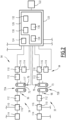
- the laying device 18 comprises a tower 30 with vertical axis B-B', defining a tower axis, at least one upper assembly 34 for gripping and moving the line 12, and at least one assembly bottom 35 for gripping and moving line 12, assemblies 34, 35 being carried by tower 30.
- the laying device 18 further comprises an assembly 36 for guiding the movement of the line 12 between the storage assembly 16 and the gripping and displacement assemblies 34, 35.
- Each assembly 34, 35 includes a support frame 70 and at least two gripping mechanisms.
- the gripping mechanisms here are track tensioners 72A, 72B carried by the frame 70.
- tensioner should be understood as a synonym of “grip mechanism”.
- Each assembly 34, 35 further comprises a sensor 76 for measuring information representative of the load applied by line 12 to tensioner 72A, 72B (visible on the figure 2 ).
- Each frame 70 is capable of being moved between an open configuration for placing the line 12 in the frame and a closed configuration for use.
- each frame 70 delimits a central passage 73 extending vertically along an axis CC' defining a laying axis of the line 12.
- This laying axis CC' is substantially parallel to the axis BB' of the tower 30 , that is to say totally parallel or inclined at an angle less than 10°, for example, with respect to the axis B-B'.
- each frame 70 advantageously carries two tensioners 72A, 72B arranged substantially parallel to each other
- Each tensioner 72A, 72B protrudes into passage 73 towards axis C-C'.
- the tensioner 72A, 72B comprises a displacement member 90, formed by a guide caterpillar intended to grip and move the line 12, two toothed wheels 92, on which the displacement member 90 is wound, a device 94 for driving the displacement member 90 along the axis B-B', and a mechanism 96 for radial displacement of each displacement member 90 towards the axis B-B'.
- the displacement member 90 substantially has the shape of an endless band wound on two toothed wheels 92. It thus has a longitudinal part 98A for guiding the pipe and a longitudinal part 98B for returning, intended to extend parallel to the C-C' laying axis.
- Guide part 98A is intended to come into contact with the outer peripheral surface of line 12, along a generatrix.
- the opposite guide sections 98A of two facing tensioners 72 face each other and are capable of gripping respectively two opposite angular sections of the line 12 with respect to the axis C-C'.
- the toothed wheels 92 are rotatable around an axis perpendicular to the axis C-C'. They are driven in rotation around their axis by the device 94, to cause the displacement of the parts 98A, 98B parallel to the axis C-C'.
- each drive device 94 comprises a motor 110, controllable by the control unit 19, advantageously a geared motor 112, connecting the motor 110 to at least one toothed wheel 92 and a mechanical brake 114 for blocking the motor 110.
- the drive device 94 advantageously comprises a sensor 116 for measuring the torque applied by each motor 110, and/or a sensor 117 for measuring the speed of movement of the line 12.
- the motor 110 is for example a hydraulic motor or an electric motor. It is capable of generating a variable torque depending on the desired configuration.
- the variable torque is selected from a line 12 holding torque in a stationary or near stationary line 12 configuration, and a line 12 moving torque through the central passage 73 in a line 12 moving configuration. .
- the mechanical brake 114 can also be controlled by the control unit 19 between a disengaged position, in which the motor 110 is free to rotate the toothed wheels 92 and an engaged position in which it is able to immobilize the motor 110 and /or each toothed wheel 92 to statically retain the line 12, even in the absence of torque applied by the motor 110.
- the radial displacement mechanism 96 comprises, for example, at least one actuator capable of radially displacing each displacement member 90 towards the laying axis C-C', in order to apply a determined force to the outer peripheral surface of the line 12.
- the control unit 19 is represented schematically on the figure 1 And 2 . It comprises for example a computer 120 and a man-machine interface 122.
- the computer 120 comprises a processor 124 and a memory 126 capable of containing functional software modules intended to be executed by the computer 124.
- the functional modules are produced at least partially in the form of programmable logic components, or else in the form of dedicated integrated circuits.
- the memory 126 contains a module 130 for selective activation of each motor 110, a module 132 for regulating each motor 110 in speed or torque, connected to each sensor 116, 117, and advantageously, a module 134 d activation of the mechanical brake 114.
- a module 136 for controlling the modules 130, 132, 134 between a rest configuration, a configuration for laying or/and recovering the line 12, a configuration of quasi-immobilization of the line 12 and a line 12 immobilizer configuration.
- the activation module 130 deactivates each motor 110 and the activation module 134 activates at least one mechanical brake 114.
- the activation module 134 deactivates each mechanical brake 114.
- the activation module 130 activates each motor 110 and the regulation module 132 controls each motor 110 in torque, or/and in speed on the basis of information received from at least one sensor 116, 117 to reach a laying and/or recovery speed greater than 2 m/hour, in particular between 2 m/hour and 2000 m/hour.
- the activation module 134 deactivates each mechanical brake 114 and activates each motor 110.
- the regulation module 132 simultaneously controls at least one motor 110 of an upper tensioner 72A and at least one motor 110 of a lower tensioner 72B to generate a continuous displacement of the displacement members 90 of the line 12, causing a continuous movement of line 12 through each traffic passage 73, at a speed of less than 1 m/hour.
- the control module 136 controls the modules 132 and 134 to carry out a succession of intervals of immobile maintenance of the line 12, in which the motors 110 of at least one upper tensioner 72A and of at least one lower tensioner 72B apply a restraining torque on line 12 without displacement of a restraining member 90 and of regulation intervals of load in which a motor 110 of an upper tensioner 72A or of an upper tensioner 72B is active to generate a limited movement of a moving member 90 of a lower tensioner 72A and/or of an upper tensioner 72B or a modification of the retaining torque applied to a moving member 90 of a lower tensioner 72A and/or an upper tensioner 72B.
- control module 136 regularly measures information representative of a difference between the load applied to at least one upper tensioner 72A and the load applied to at least one lower tensioner 72B using the sensors 76, and moves a displacement member 90 of the lower tensioner 72B or/and of the upper tensioner 72A by the motor 110, or modify the torque applied to a displacement member 90 of the lower tensioner 72B or/and of the upper tensioner 72A by the motor 110 according to the representative measured information.
- the control module 136 activates the motor 110 of a lower tensioner 72B to move a moving member 90 of the lower tensioner 72B or to modify the holding torque applied to the displacement member 90 of the lower tensioner 72B until the measured load difference is less than or equal to the predetermined threshold.
- the man-machine interface 122 comprises for example a control member, in particular a joystick and/or a touch screen, and a display to allow the control unit 19 to switch between the rest configuration, the laying configuration or /and recovery, the quasi-immobilization configuration and the immobilization configuration of line 12. It is suitable for allowing the user to select a speed of laying or/and recovery of line 12 in the configuration of installation and/or recovery.
- the guide assembly 34 comprises at least one curved guide chute 140 or a wheel arranged above the tower 30 to redirect the flexible line 12 taken from the storage assembly 16 in the axis of the tower 30.
- the chute 140 has a substantially downward U-shape defining an adequate radius of curvature for the line 12. This radius of curvature is greater than the minimum radius of curvature (MBR) of the line 12.
- the flexible line 12 is stored in the storage assembly 16 by being wound on the rotary member 28.
- Line 12 thus retains an adequate radius of curvature greater than its MBR.
- the system 10 is then moved over the expanse of water 11 to a laying region in which the line 12 is to be deployed.
- the respective frames 70 of the gripping and displacement assemblies 34, 35 are at least partially open.
- the mechanisms 96 for radial displacement of the displacement members 90 are then activated to apply each longitudinal guide part 98A against the outer peripheral surface of the line 12 along a generatrix of the latter.
- the radial displacement mechanisms 96 are also driven to apply a predetermined pressure on the line 12.
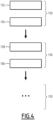
- an installation phase 150 is then performed.
- the control unit 19 switches to its installation configuration. It activates the motors 110 at step 152, and controls the motors at step 154 to develop a torque to move the mover 90. This causes a continuous movement of the line 12 through the circulation passages 73 , regulated at a displacement speed greater than 2 m/hour, in particular between 2 m/hour and 2000 m/hour.
- the device 94 for driving the toothed wheels 92 in rotation is activated.
- the displacement members 90 are driven in motion, so that each longitudinal part 98A moves from top to bottom while driving the line 12.
- the line 12 is thus driven in translation along the laying axis C-C' by the members displacement 90 of the tensioners 72A, 72B next to each set 34, 35.
- a phase of quasi- immobilization 156 is then implemented.
- control unit 19 switches to the quasi-immolation configuration at step 158.
- step 160 It simultaneously activates and controls at least one motor 110 of an upper tensioner 72A and at least one motor 110 of a lower tensioner 72B (step 160), to generate a continuous displacement of the displacement members 90 causing a continuous movement of the line 12 through each circulation passage 73, at a speed of less than 1 m/hour, in particular less than 0.25 m/hour.
- Simultaneous control 160 advantageously includes the measurement of information representative of a difference between the load applied by line 12 to at least one upper tensioner 72A and the load applied to line 12 by at least one lower tensioner 72B at the using sensors 76.
- Simultaneous control 160 comprises the selective control of at least one motor 110 of an upper tensioner 72A and of at least one motor 110 of a lower tensioner 72B according to the measured load difference, to maintain the load difference below a certain threshold.
- the second process illustrated by the figure 5 differs from the process illustrated by the figure 4 in that it comprises at least one phase 170 of immobilization of line 12.
- the immobilization phase 170 comprises a succession of intervals 172 for keeping line 12 immobile, and load regulation intervals 174.
- the control unit 19 regularly measures information representative of a difference between the load applied by line 12 to at least one upper tensioner 72A and the load applied to line 12 by at least one lower tensioner 72B using the sensors 76.
- a regulation interval 174 is executed by the control unit 19.
- a motor 110 of one of an upper tensioner 72A or of a lower tensioner 72B is activated to generate a movement of a displacement member 90 of the upper tensioner 72A or of the lower tensioner 72B.
- the motor 110 of the other of the upper tensioner 72A or of the lower tensioner 72B remains active, but without displacement of its displacement member 90.
- the motor of at least one lower tensioner 72B is activated to cause movement of the displacement member 90 of the lower tensioner 72B.
- the motor 110 of each upper tensioner 72A remains active to apply to the displacement member 90 of the upper tensioner 72A a retaining torque of the line 12 against its weight, but without displacement of the displacement member 90 of the 72A top tensioner.
- the displacement of the displacement member of the lower tensioner 72A by the motor 110 is then controlled according to the representative information measured so that the difference between the load applied by line 12 on at least one upper tensioner 72A and the load applied on line 12 by at least one lower tensioner 72B, measured using sensors 76, goes below the predetermined threshold.
- a motor 110 of one of an upper tensioner 72A or of a lower tensioner 72B is activated to generate a modification of the retaining torque applied to a displacement member 90 of the upper tensioner 72A or the lower tensioner 72B, without moving the upper tensioner 72A or the lower tensioner 72B.
- the motor 110 of the other of the upper tensioner 72A or of the lower tensioner 72B remains active, but without modification of the torque applied to its displacement member 90 and without displacement of the upper tensioner 72A or of the lower tensioner 72B.
- the motor of at least one lower tensioner 72B is activated to generate a modification of the torque applied to the moving member 90 of the lower tensioner 72B.
- the motor 110 of each upper tensioner 72A remains active to apply to the displacement member 90 of the upper tensioner 72A the same retaining torque of the line 12 against its weight, without displacement of the displacement member 90 of the 72A top tensioner.
- the torque applied to the displacement member of the lower tensioner 72A by the motor 110 is then controlled according to the representative information measured so that the difference between the load applied by the line 12 on at least one tensioner upper 72A and the load applied to line 12 by at least one lower tensioner 72B, measured using sensors 76, falls below the predetermined threshold.
- the third process illustrated on the figure 6 differs from the second process illustrated on the figure 5 in that during the immobilization phase 170, a mechanical brake 114 is permanently applied to at least one upper tensioner 72A to immobilize the upper tensioner 72A (step 180).
- the motor 110 of at least one lower tensioner 72B is activated to cause a displacement of a displacement member 90 of the lower tensioner 72B.
- the method includes the measurement of information representative of a difference between the load applied by line 12 to at least one upper tensioner 72A and the load applied to line 12 by at least one lower tensioner 72B at the using sensors 76.
- the method then includes the activation of at least one lower tensioner 72B to cause movement of the displacement member 90 of the lower tensioner 72B.
- the displacement of the displacement member of the lower tensioner 72A by the motor 110 is then controlled according to the representative information measured so that the difference between the load applied by line 12 on at least one upper tensioner 72A and the load applied to line 12 by at least one lower tensioner 72B, measured using sensors 76, falls below the predetermined threshold.
- the brake 114 of the upper tensioner 72A remains active during the regulation interval 174.
- the motor 110 of at least one lower tensioner 72B is activated to modify the torque applied to a displacement member 90 of the lower tensioner 72B, without displacement of the displacement member 90 of the lower tensioner 72B.
- the method includes the measurement of information representative of a difference between the load applied by line 12 to at least one upper tensioner 72A and the load applied to line 12 by at least one lower tensioner 72B at the using sensors 76.
- the method then comprises the activation of at least one motor 110 of a lower tensioner 72B to generate a modification of the retaining torque applied to the moving member 90 of the lower tensioner 72B.
- the torque applied to the displacement member of the lower tensioner 72B by the motor 110 is then controlled according to the representative information measured so that the difference between the load applied by line 12 on at least one upper tensioner 72A and the load applied to line 12 by at least one lower tensioner 72B, measured using sensors 76, drops below the predetermined threshold.
- the brake 114 of the upper tensioner 72A remains active during the regulation interval 174.
- a mechanical brake 114 is permanently applied to at least one lower tensioner 72B to immobilize the lower tensioner 72B.
- the motor 110 of at least one upper tensioner 72A is activated to cause a displacement of a displacement member 90 of the upper tensioner 72A or a modification of the torque applied to the displacement member 90 of the upper tensioner 72A without displacement of the upper tensioner 72A.
- the second and the third method according to the invention make it possible to immobilize the line 12 in order to carry out operations thereon, without generating any substantial difference in load applying between the tensioners.
- the second and third methods according to the invention also lead to a total immobilization of the line 12 allowing interventions in complete safety, limiting the risks for the personnel working on the line.
Landscapes
- Engineering & Computer Science (AREA)
- General Engineering & Computer Science (AREA)
- Mechanical Engineering (AREA)
- Bridges Or Land Bridges (AREA)
- Controlling Rewinding, Feeding, Winding, Or Abnormalities Of Webs (AREA)
- Processing Of Solid Wastes (AREA)
- Tension Adjustment In Filamentary Materials (AREA)
- Supports For Pipes And Cables (AREA)
- Lining Or Joining Of Plastics Or The Like (AREA)
Claims (15)
- Verfahren zum Verlegen oder/und Einholen einer flexiblen Leitung (12) in einem Gewässer (11), umfassend:- Bereitstellen einer Verlegevorrichtung (18), umfassend ein Paar obere Spanner (72A) und ein Paar untere Spanner (72B), wobei jedes Paar Spanner (72A; 72B) einen Durchgang (73) für den Umlauf der Leitung (12) definiert, in dem die Leitung (12) lokal eingeklemmt wird; wobei jeder Spanner (72A; 72B) ein Element (90) zum Bewegen der Leitung (12) und mindestens einen Motor (110) zum Bewegen des Bewegungselements (90) umfasst, der aktiviert werden kann, um ein Drehmoment zum Bewegen der Leitung (12) zu entwickeln;- eine Einheit (19) zum Steuern von jedem Motor (110),das Verfahren umfassend:
mindestens eine Verlege- und/oder Einholphase, in der die Steuereinheit (19) den Motor (110) mindestens eines Spanners (72A; 72B) aktiviert und ein Bewegungsmoment entwickelt, das eine kontinuierliche Bewegung der Leitung (12) durch jeden Umlaufdurchgang (73) erzeugt;- mindestens eine Quasiimmobilisierungs- oder Immobilisierungsphase der Leitung;dadurch gekennzeichnet, dass die oder jede Quasiimmobilisierungs- oder Immobilisierungsphase der Leitung die folgenden Schritte umfasst:- Aktivieren des Motors von mindestens einem oberen Spanner (72A) und/oder mindestens einem unteren Spanner (72B) durch die Steuereinheit (19), um auf das Bewegungselement des oberen Spanners (72A) und/oder des unteren Spanners (72B) ein Rückhaltemoment der Leitung (12) gegen ihr Gewicht durch das Paar oberer Spanner (72A) oder/und durch das Paar unterer Spanner (72B) zu übertragen,- zumindest punktuelles Ansteuern mindestens eines Motors (110) eines oberen Spanners (72A) und/oder eines unteren Spanners (72B) durch die Steuereinheit (19), um eine Bewegung eines Bewegungselements (90) des oberen Spanners (72A) und/oder des unteren Spanners (72B) zu erzeugen oder um das auf das Bewegungselement (90) des oberen Spanners (72A) oder/und des unteren Spanners (72B) ausgeübte Rückhaltemoment ohne Bewegung des Bewegungselements (90) des oberen Spanners (72A) oder/und des unteren Spanners (72B) zu verändern. - Verfahren nach Anspruch 1, umfassend mindestens eine Quasiimmobilisierungsphase der Leitung (12), in der die Steuereinheit (19) gleichzeitig mindestens einen Motor (110) eines oberen Spanners (72A) und mindestens einen Motor (110) eines unteren Spanners (72B) steuert, um eine kontinuierliche Bewegung der Bewegungselemente (90) der Leitung (12) zu erzeugen, die eine kontinuierliche Bewegung der Leitung (12) durch jeden Durchgang (73) mit einer Geschwindigkeit von weniger als 1 m/Stunde bewirkt.
- Verfahren nach Anspruch 2, wobei in der Verlege- und/oder Einholphase der Leitung (12) die kontinuierliche Bewegung der Leitung (12) höher als 1,5 m/Stunde ist.
- Verfahren nach Anspruch 2 oder 3, wobei die gleichzeitige Ansteuerung mindestens eines Motors (110) eines oberen Spanners (72A) und mindestens eines Motors (110) eines unteren Spanners (72B), um eine kontinuierliche Bewegung der Bewegungselemente (90) der Leitung (12) zu erzeugen, eine Messung von Informationen, die repräsentativ für eine Differenz zwischen der Last des oberen Spanners (72A) und der Last des unteren Spanners (72B) sind, und die selektive Steuerung von mindestens einem Motor (110) eines oberen Spanners (72A) und mindestens einem Motor (110) eines unteren Spanners (72B) abhängig von der gemessenen Lastdifferenz umfasst.
- Verfahren nach einem der vorherigen Ansprüche, mindestens umfassend eine Immobilisierungsphase der Leitung (12), die Immobilisierungsphase der Leitung (12) umfassend eine Abfolge von Halteintervallen (172) der Leitung (12), in denen die Motoren (110) mindestens eines oberen Spanner (72A) und eines unteren Spanners (72B) das Rückhaltemoment ohne Bewegung eines Bewegungselements (90) auf die Leitung (12) übertragen, und von Regulierungsintervallen (174) der Last, in denen ein Motor (110) eines oberen Spanners (72A) oder eines oberen Spanners (72A) aktiv ist, um eine Bewegung eines Bewegungselements (90) des unteren Spanners (72B) und/oder des oberen Spanners (72A) zu erzeugen, oder eine Änderung des auf das Bewegungselement (90) des oberen Spanners (72A) oder/und des unteren Spanners (72B) ausgeübten Haltemoments ohne Bewegung des Bewegungselements (90) des oberen Spanners (72A) oder/und des unteren Spanners (72B) zu bewirken.
- Verfahren nach Anspruch 5, wobei in jedem Regulierungsintervall (174) der Motor (110) von mindestens einem unteren Spanner (72B) aktiviert wird, um ohne Bewegung des unteren Spanners (72B) eine Bewegung eines Bewegungselements (90) des unteren Spanners (72B) oder eine Änderung des auf das Bewegungselement (90) des unteren Spanners (72B) ausgeübten Rückhaltemoments zu bewirken, wobei der Motor (110) von jedem oberen Spanner (72A) aktiviert wird, um ohne Bewegung des Bewegungselements (90) des oberen Spanners (72A) ein Rückhaltemoment der Leitung (12) gegen ihr Gewicht auf das Bewegungselement (90) des oberen Spanners (72A) zu übertragen.
- Verfahren nach Anspruch 5, wobei während der Immobilisierungsphase (174) eine mechanische Bremse permanent auf mindestens einen oberen Spanner (72A) angewendet wird, um den oberen Spanner (72A) zu immobilisieren, und wobei während jedes Regulierungsintervalls (174) der Motor (110) von mindestens einem unteren Spanner (72B) aktiviert wird, eine Bewegung eines Bewegungselements (90) des unteren Spanners (72B) oder eine Änderung des auf das Bewegungselement (90) des unteren Spanners (72B) ausgeübten Drehmoments ohne Bewegung des unteren Spanners (72B) zu erzeugen,
oder wobei während der Immobilisierungsphase (174) eine mechanische Bremse permanent an mindestens einen unteren Spanner (72B) angelegt wird, um den unteren Spanner (72B) zu immobilisieren, und wobei während jedes Regulierungsintervalls (174) der Motor (110) von mindestens einem oberen Spanner (72A) aktiviert wird, um eine Bewegung eines Bewegungselements (90) des oberen Spanners (72A) oder eine Änderung des auf das Bewegungselement (90) des oberen Spanners (72A) ausgeübten Drehmoments ohne Bewegung des oberen Spanners (72A) zu erzeugen. - Verfahren nach einem der Ansprüche 5 bis 7, umfassend das Messen von Informationen, die repräsentativ sind für eine Differenz zwischen der ausgeübten Last auf mindestens einen oberen Spanner (72A) und der ausgeübten Last auf mindestens einen unteren Spanner (72B), die Bewegung eines Bewegungselements (90) des unteren Spanners (72B) und/oder des oberen Spanners (72A) durch den Motor (110) während jedes Regulierungsintervalls (174) oder das auf das Bewegungselement (90) des unteren Spanners (72B) oder/und des oberen Spanners (72A) ausgeübte Drehmoment durch den Motor (110) in jedem Regulierungsintervall (174) abhängig von den repräsentativen Informationen gesteuert wird.
- Verfahren nach Anspruch 7 oder 8, wobei die Bewegung eines Bewegungselements (90) des unteren Spanners (72B) oder/und des oberen Spanners (72A) durch den Motor (110) während jedes Regulierungsintervalls (174) oder die Änderung des auf das Bewegungselement (90) des oberen Spanners (72A) oder/und des unteren Spanners (72B) ausgeübten Rückhaltemoments durchgeführt werden, wenn die Differenz der Last einen ersten vordefinierten Schwellenwert überschreitet, und angehalten wird. wenn die Differenz der Last unter einen zweiten vordefinierten Schwellenwert fällt, der vorteilhafterweise kleiner als oder gleich wie der erste vordefinierte Schwellenwert ist.
- System (10) zum Verlegen oder/und Einholen einer flexiblen Leitung (12) in einem Gewässer (11), umfassend:- eine Verlegevorrichtung (18), umfassend ein Paar oberer Spanner (72A) und ein Paar unterer Spanner (72B), wobei jedes Paar Spanner (72A; 72B) einen Umlaufdurchgang (73) der Leitung (12) definiert, in dem die Leitung (12) lokal eingeklemmt ist;
jede Spanner (72A; 72B) umfassend ein Bewegungselement (90) der Leitung (12) und mindestens einen Motor (110) zum Inbewegungsetzen des Bewegungselements (90), der aktiviert werden kann, um ein Bewegungsdrehmoment der Leitung (12) zu entwickeln;- eine Steuereinheit von jedem Motor (110), die zur Ausführung von Folgendem geeignet ist:- mindestens eine Verlege- und/oder Einholphase, in der die Steuereinheit den Motor (110) mindestens eines Spanners (72A; 72B) aktiviert und ein Bewegungsmoment entwickelt, das eine kontinuierliche Bewegung der Leitung (12) durch jeden Umlaufdurchgang (73) erzeugt;- mindestens eine Quasiimmobilisierungs- oder Immobilisierungsphase der Leitung (12); dadurch gekennzeichnet, dass während der oder jeder Quasiimmobilisierungs- oder Immobilisierungsphase der Leitung (12) die Steuereinheit zu Folgendem geeignet ist:- Aktivieren eines Motors (110) von mindestens einem oberen Spanner (72A) und/oder mindestens einem unteren Spanner (72B), um auf das Bewegungselement (90) des oberen Spanners (72A) und/oder des unteren Spanners (72B) ein Rückhaltemoment der Leitung (12) gegen ihr Gewicht durch das Paar von oberen Spannern (72A) oder/und durch das Paar von unteren Spannern (72B) zu übertragen,- Steuern, zumindest punktuell, mindestens eines Motors (110) eines oberen Spanners (72A) und/oder eines unteren Spanners (72B), um eine Bewegung eines Bewegungselements (90) des oberen Spanners (72A) und/oder des unteren Spanners (72B) zu erzeugen oder um das auf das Bewegungselement (90) des oberen Spanners (72A) oder/und des unteren Spanners (72B) ausgeübte Rückhaltemoment ohne Bewegung des Bewegungselements (90) des oberen Spanners (72A) oder/und des unteren Spanners (72B) zu ändern. - System (10) nach Anspruch 10, wobei die Steuereinheit (19) geeignet ist, um eine Quasiimmobilisierungsphase der Leitung (12) auszuführen, in der die Steuereinheit (19) gleichzeitig mindestens einen Motor (110) eines oberen Spanners (72A) und einen Motor (110) eines unteren Spanners (72B) steuert, um eine kontinuierliche Bewegung der Bewegungselemente (90) der Leitung (12) zu erzeugen, die eine kontinuierliche Bewegung der Leitung (12) durch jeden Umlaufdurchgang (73) mit einer Geschwindigkeit von weniger als 1 m/Stunde bewirkt.
- System (10) nach Anspruch 10, wobei die Steuereinheit (19) geeignet ist, um mindestens eine Immobilisierungsphase der Leitung (12) auszuführen, die Immobilisierungsphase der Leitung (12) umfassend eine Abfolge von Intervallen (172), um die Leitung (12) immobilisiert zu halten, in denen die Motoren (110) mindestens eines oberen Spanner (72A) und eines unteren Spanners (72B) das Rückhaltemoment ohne Bewegung eines Rückhalteelements (190) auf die Leitung (12) übertragen, und von Regulierungsintervallen (174) der Last, in denen ein Motor (110) eines oberen Spanners (72A) oder eines oberen Spanners (72A) aktiv ist, um eine Bewegung eines Bewegungselements (90) des unteren Spanners (72B) und/oder des oberen Spanners (72A) zu erzeugen, oder um das auf das Bewegungselement (90) des oberen Spanners (72A) oder/und des unteren Spanners (72B) ausgeübte Haltemoment ohne Bewegung des Bewegungselements (90) des oberen Spanners (72A) oder/und des unteren Spanners (72B) zu ändern.
- System nach Anspruch 12, wobei die Steuereinheit (19) während jedes Regulierungsintervalls (174) geeignet ist, um den Motor (110) mindestens eines unteren Spanners (72B) zu aktivieren, um eine Bewegung eines Bewegungsorgans (90) des unteren Spanners (72B) oder eine Änderung des auf das Bewegungsorgan (90) des unteren Spanners (72B) ausgeübten Rückhaltemoments ohne Bewegung des unteren Spanners (72B) zu bewirken, wobei der Motor (110) von jedem oberen Spanner (72A) aktiviert wird, um ohne Bewegung des Bewegungselements (90) des oberen Spanners (72A) ein Rückhaltemoment der Leitung (12) gegen ihr Gewicht auf das Bewegungselement (90) des oberen Spanners (72A) zu übertragen.
- System nach Anspruch 12, wobei die Verlegevorrichtung mindestens eine mechanische Bremse (114) umfasst, die geeignet ist, um mindestens einen Motor (110) eines oberen Spanners (72A) mechanisch zu immobilisieren, der durch die Steuereinheit (19) aktiviert werden kann, wobei die Steuereinheit (19) während jeder Immobilisierungsphase geeignet ist, um die mechanische Bremse (114) permanent auf mindestens einen oberen Spanner (72A) anzuwenden, um den oberen Spanner (72A) zu immobilisieren, und während jedes Regulierungsintervalls (174) den Motor (110) von mindestens einem unteren Spanner (72B) zu aktivieren, um eine Bewegung eines Bewegungselements (90) des unteren Spanners (72B) zu bewirken oder das auf das Bewegungselement (90) des unteren Spanners (72B) ausgeübte Rückhaltemoment ohne Bewegung des unteren Spanners (72B) zu ändern;
oder wobei die Verlegevorrichtung mindestens eine mechanische Bremse (114) umfasst, die geeignet ist, um mindestens einen Motor (110) eines unteren Spanners (72B) mechanisch zu immobilisieren, der durch die Steuereinheit (19) aktiviert werden kann, wobei die Steuereinheit (19) während jeder Immobilisierungsphase geeignet ist, um die mechanische Bremse (114) permanent auf mindestens einen unteren Spanner (72B) anzuwenden, um den unteren Spanner (72B) zu immobilisieren, und während jedes Regulierungsintervalls (174) den Motor (110) von mindestens einem oberen Spanner (72A) zu aktivieren, um eine Bewegung eines Bewegungselements (90) des oberen Spanners (72A) zu bewirken oder das auf das Bewegungselement (90) des oberen Spanners (72A) ausgeübte Rückhaltemoment ohne Bewegung des oberen Spanners (72A) zu ändern; - System (10) nach einem der Ansprüche 10 bis 14, umfassend mindestens einen Sensor (76) zum Messen von Informationen, die repräsentativ sind für eine Differenz zwischen der ausgeübten Last auf mindestens einen oberen Spanner (72A) und der ausgeübten Last auf mindestens einen unteren Spanner (72B), wobei die Steuereinheit (19) geeignet ist, um den Motor (110) zur Bewegung eines Bewegungsorgans (90) des unteren Spanners (72B) oder/und des oberen Spanners (72A) während jedes Regulierungsintervalls (174) abhängig von den repräsentativen Informationen zu steuern.
Applications Claiming Priority (2)
| Application Number | Priority Date | Filing Date | Title |
|---|---|---|---|
| FR1874403A FR3091326B1 (fr) | 2018-12-31 | 2018-12-31 | Procédé de pose ou/et de récupération d'une ligne flexible dans une étendue d'eau et système associé |
| PCT/EP2019/087188 WO2020141172A1 (fr) | 2018-12-31 | 2019-12-31 | Procédé de pose ou/et de récupération d'une ligne flexible dans une étendue d'eau et système associé |
Publications (3)
| Publication Number | Publication Date |
|---|---|
| EP3906375A1 EP3906375A1 (de) | 2021-11-10 |
| EP3906375B1 true EP3906375B1 (de) | 2023-06-07 |
| EP3906375B8 EP3906375B8 (de) | 2023-07-12 |
Family
ID=66530324
Family Applications (1)
| Application Number | Title | Priority Date | Filing Date |
|---|---|---|---|
| EP19835430.0A Active EP3906375B8 (de) | 2018-12-31 | 2019-12-31 | Verfahren zur verlegung und/oder rückgewinnung einer flexiblen leitung in einem gewässer und zugehöriges system |
Country Status (7)
| Country | Link |
|---|---|
| US (1) | US11746926B2 (de) |
| EP (1) | EP3906375B8 (de) |
| AU (1) | AU2019417977B2 (de) |
| DK (1) | DK3906375T3 (de) |
| FR (1) | FR3091326B1 (de) |
| MY (1) | MY202088A (de) |
| WO (1) | WO2020141172A1 (de) |
Families Citing this family (3)
| Publication number | Priority date | Publication date | Assignee | Title |
|---|---|---|---|---|
| GB2611020A (en) * | 2021-08-19 | 2023-03-29 | Offshore Projects Alliance Ltd | Method and system for deploying an elongate member |
| DK4534401T3 (da) * | 2023-10-04 | 2026-04-20 | Technipfmc Subsea France | Genvindingsanlæg til genvinding af en undersøisk ledning i et vandområde samt tilsvarende fremgangsmåde til genvinding |
| EP4538500A1 (de) * | 2023-10-12 | 2025-04-16 | TechnipFMC Subsea France | Rückgewinnungsverfahren zur rückgewinnung einer flexiblen leitung in einem gewässer und zugehörige anlage |
Family Cites Families (10)
| Publication number | Priority date | Publication date | Assignee | Title |
|---|---|---|---|---|
| DE2648264C2 (de) * | 1976-10-25 | 1978-09-07 | Licentia Patent-Verwaltungs-Gmbh, 6000 Frankfurt | Regeleinrichtung zum Rohrverlegen im tiefen Wasser mit kombinierter Rohrverleger- und Tensioner-Regelung |
| FR2792990B1 (fr) | 1999-04-30 | 2001-06-08 | Coflexip | Navire de pose de conduite rigides a grandes profondeurs |
| ATE530830T1 (de) * | 2005-02-08 | 2011-11-15 | Itrec Bv | System zur verlegung von rohren im meer und verfahren zur installierung von offshore-rohren mit einem oder mehreren zubehörteilen |
| BRPI0621558B1 (pt) | 2006-03-22 | 2018-04-24 | Itrec B.V. | Sistema de instalação de tubulação submarina para assentamento de uma tubulação fora-da- costa e/ou instalação de um tubo ascendente submarino, e, método de instalação de um tubo ascendente submarino |
| GB0715999D0 (en) * | 2007-08-16 | 2007-09-26 | Acergy Uk Ltd | Method andapparatus for laying offshore pipeline from a vessel |
| FR2970056B1 (fr) * | 2011-01-04 | 2014-02-14 | Technip France | Dispositif de pose d'une conduite dans une etendue d'eau, structure et procede associes |
| GB201104715D0 (en) * | 2011-03-21 | 2011-05-04 | Saipem Spa | A/R Method and apparatus therefor |
| GB2492402B (en) * | 2011-07-01 | 2013-10-09 | Technip France | Marine pipeline-installation tower and tensioning assembly |
| GB2505868A (en) * | 2012-07-10 | 2014-03-19 | Ceona Services Uk Ltd | An apparatus and method for laying a submarine pipeline |
| NL2010511C2 (en) * | 2013-03-22 | 2014-09-24 | Itrec Bv | Marine pipeline installation vessel and method. |
-
2018
- 2018-12-31 FR FR1874403A patent/FR3091326B1/fr active Active
-
2019
- 2019-12-31 DK DK19835430.0T patent/DK3906375T3/da active
- 2019-12-31 MY MYPI2021003682A patent/MY202088A/en unknown
- 2019-12-31 EP EP19835430.0A patent/EP3906375B8/de active Active
- 2019-12-31 AU AU2019417977A patent/AU2019417977B2/en active Active
- 2019-12-31 US US17/419,362 patent/US11746926B2/en active Active
- 2019-12-31 WO PCT/EP2019/087188 patent/WO2020141172A1/fr not_active Ceased
Also Published As
| Publication number | Publication date |
|---|---|
| FR3091326B1 (fr) | 2021-04-02 |
| FR3091326A1 (fr) | 2020-07-03 |
| MY202088A (en) | 2024-04-03 |
| EP3906375A1 (de) | 2021-11-10 |
| US11746926B2 (en) | 2023-09-05 |
| EP3906375B8 (de) | 2023-07-12 |
| WO2020141172A1 (fr) | 2020-07-09 |
| BR112021012867A2 (pt) | 2021-09-21 |
| DK3906375T3 (da) | 2023-09-04 |
| US20220082182A1 (en) | 2022-03-17 |
| AU2019417977B2 (en) | 2025-06-26 |
| AU2019417977A1 (en) | 2021-07-22 |
Similar Documents
| Publication | Publication Date | Title |
|---|---|---|
| EP3906375B1 (de) | Verfahren zur verlegung und/oder rückgewinnung einer flexiblen leitung in einem gewässer und zugehöriges system | |
| EP1092108B1 (de) | Schiff zum verlegen von starren rohrleitungen in grosser tiefe | |
| EP1385780B1 (de) | Flüssigkeitstransferierungssystem, insbesondere lng, zwischen einem transportfahrzeug, wie ein schiff, und eine empfangs- oder lieferstation für dieses produkt | |
| FR2859495A1 (fr) | Methode d'installation et de connexion d'une conduite sous-marine montante | |
| WO1994024377A1 (fr) | Procede et dispositif de pose et d'ensouillage en continu d'une conduite flexible sous-marine | |
| EP1913229B1 (de) | Unterwassersystem mit einem biegsamen rohr mit verstellbarer krümmung | |
| FR2801088A1 (fr) | Systeme de pinces pour maintenir une conduite en tension, et support flottant en comprenant | |
| FR2590539A1 (fr) | Systeme d'amarrage a cable unique, et procede de realisation d'un terminal de haute mer utilisant un tel systeme | |
| EP2661576B1 (de) | Vorrichtung zum verlegen einer rohrleitung in einer wasserbedeckten fläche und diesbezügliche struktur und verfahren | |
| EP1173698A1 (de) | Vorrichtung für die verbindung und die verlegung der aufeinanderfolgenden teile einer unterwasserleitung von einem schiff und deren verwendungen | |
| EP0474845B1 (de) | Verfahren zum verlegen von biegsamen rohrförmigen leitungen mittels einer vielzahl von schiffen | |
| EP0020257A1 (de) | Vorrichtung zum J-förmigen Verlegen einer Unterwasserrohrleitung | |
| EP2571753B1 (de) | Vorrichtung für eine verbindung zwischen meeresgrund und oberfläche mit einer flexiblen rohrführungsstruktur | |
| EP3209546A1 (de) | System zum aussetzen und bergen von see- und unterseevorrichtungen mit unterstützung durch kippbare schutzkomponenten | |
| FR2765183A1 (fr) | Navires de relevements sismiques | |
| EP3987207B1 (de) | Verfahren zum verlegen und/oder zurückholen einer leitung in einem gewässer, mit einer phase der gesteuerten immobilisierung | |
| EP3004707B1 (de) | Vorrichtung zum verlegen eines länglichen elements in einem gewässer, zugehörige anlage und zugehöriges verfahren | |
| FR2938001A1 (fr) | Procede de montage d'une tour d'exploitation d'un fluide dans une etendue d'eau et tour d'exploitation associee. | |
| WO2013150079A1 (fr) | Procede de positionnement d'un ensemble de fond au fond d'une etendue d'eau, et dispositif associe | |
| EP0677753B1 (de) | Verfahren und Vorrichtung für die diskontinuierliche Vorwärtsbewegung eines den Meeresboden berührenden Objektes | |
| EP4101806B1 (de) | Unterwasserausrüstung zum spannen von ankerleinen einer offshore-struktur und verfahren zur installation einer solchen ausrüstung | |
| EP2640923B1 (de) | Turm in einem wasserkörper zur erschliessung einer flüssigkeit und zugehöriges installationsverfahren | |
| FR2934663A1 (fr) | Methode d'installation d'une conduite tubulaire sur le fond marin | |
| BR112021012867B1 (pt) | Método para assentar e/ou recuperar uma tubulação flexível em um corpo dágua e sistema para assentar e/ou recuperar uma tubulação flexível em um corpo dágua | |
| FR2549803A1 (fr) | Bossoir a longue portee pour embarcation de sauvetage |
Legal Events
| Date | Code | Title | Description |
|---|---|---|---|
| STAA | Information on the status of an ep patent application or granted ep patent |
Free format text: STATUS: UNKNOWN |
|
| STAA | Information on the status of an ep patent application or granted ep patent |
Free format text: STATUS: THE INTERNATIONAL PUBLICATION HAS BEEN MADE |
|
| PUAI | Public reference made under article 153(3) epc to a published international application that has entered the european phase |
Free format text: ORIGINAL CODE: 0009012 |
|
| STAA | Information on the status of an ep patent application or granted ep patent |
Free format text: STATUS: REQUEST FOR EXAMINATION WAS MADE |
|
| 17P | Request for examination filed |
Effective date: 20210628 |
|
| AK | Designated contracting states |
Kind code of ref document: A1 Designated state(s): AL AT BE BG CH CY CZ DE DK EE ES FI FR GB GR HR HU IE IS IT LI LT LU LV MC MK MT NL NO PL PT RO RS SE SI SK SM TR |
|
| DAV | Request for validation of the european patent (deleted) | ||
| DAX | Request for extension of the european patent (deleted) | ||
| GRAP | Despatch of communication of intention to grant a patent |
Free format text: ORIGINAL CODE: EPIDOSNIGR1 |
|
| STAA | Information on the status of an ep patent application or granted ep patent |
Free format text: STATUS: GRANT OF PATENT IS INTENDED |
|
| INTG | Intention to grant announced |
Effective date: 20230110 |
|
| RAP3 | Party data changed (applicant data changed or rights of an application transferred) |
Owner name: TECHNIPFMC SUBSEA FRANCE |
|
| GRAS | Grant fee paid |
Free format text: ORIGINAL CODE: EPIDOSNIGR3 |
|
| GRAA | (expected) grant |
Free format text: ORIGINAL CODE: 0009210 |
|
| STAA | Information on the status of an ep patent application or granted ep patent |
Free format text: STATUS: THE PATENT HAS BEEN GRANTED |
|
| AK | Designated contracting states |
Kind code of ref document: B1 Designated state(s): AL AT BE BG CH CY CZ DE DK EE ES FI FR GB GR HR HU IE IS IT LI LT LU LV MC MK MT NL NO PL PT RO RS SE SI SK SM TR |
|
| REG | Reference to a national code |
Ref country code: GB Ref legal event code: FG4D Free format text: NOT ENGLISH |
|
| REG | Reference to a national code |
Ref country code: CH Ref legal event code: PK Free format text: RECTIFICATION B8 Ref country code: CH Ref legal event code: EP Ref country code: AT Ref legal event code: REF Ref document number: 1575997 Country of ref document: AT Kind code of ref document: T Effective date: 20230615 Ref country code: DE Ref legal event code: R096 Ref document number: 602019030685 Country of ref document: DE |
|
| P01 | Opt-out of the competence of the unified patent court (upc) registered |
Effective date: 20230522 |
|
| RAP4 | Party data changed (patent owner data changed or rights of a patent transferred) |
Owner name: TECHNIPFMC SUBSEA FRANCE |
|
| REG | Reference to a national code |
Ref country code: NL Ref legal event code: FP |
|
| REG | Reference to a national code |
Ref country code: DK Ref legal event code: T3 Effective date: 20230828 |
|
| REG | Reference to a national code |
Ref country code: LT Ref legal event code: MG9D |
|
| REG | Reference to a national code |
Ref country code: NO Ref legal event code: T2 Effective date: 20230607 |
|
| PG25 | Lapsed in a contracting state [announced via postgrant information from national office to epo] |
Ref country code: SE Free format text: LAPSE BECAUSE OF FAILURE TO SUBMIT A TRANSLATION OF THE DESCRIPTION OR TO PAY THE FEE WITHIN THE PRESCRIBED TIME-LIMIT Effective date: 20230607 Ref country code: ES Free format text: LAPSE BECAUSE OF FAILURE TO SUBMIT A TRANSLATION OF THE DESCRIPTION OR TO PAY THE FEE WITHIN THE PRESCRIBED TIME-LIMIT Effective date: 20230607 |
|
| REG | Reference to a national code |
Ref country code: AT Ref legal event code: MK05 Ref document number: 1575997 Country of ref document: AT Kind code of ref document: T Effective date: 20230607 |
|
| PG25 | Lapsed in a contracting state [announced via postgrant information from national office to epo] |
Ref country code: RS Free format text: LAPSE BECAUSE OF FAILURE TO SUBMIT A TRANSLATION OF THE DESCRIPTION OR TO PAY THE FEE WITHIN THE PRESCRIBED TIME-LIMIT Effective date: 20230607 Ref country code: LV Free format text: LAPSE BECAUSE OF FAILURE TO SUBMIT A TRANSLATION OF THE DESCRIPTION OR TO PAY THE FEE WITHIN THE PRESCRIBED TIME-LIMIT Effective date: 20230607 Ref country code: LT Free format text: LAPSE BECAUSE OF FAILURE TO SUBMIT A TRANSLATION OF THE DESCRIPTION OR TO PAY THE FEE WITHIN THE PRESCRIBED TIME-LIMIT Effective date: 20230607 Ref country code: HR Free format text: LAPSE BECAUSE OF FAILURE TO SUBMIT A TRANSLATION OF THE DESCRIPTION OR TO PAY THE FEE WITHIN THE PRESCRIBED TIME-LIMIT Effective date: 20230607 Ref country code: GR Free format text: LAPSE BECAUSE OF FAILURE TO SUBMIT A TRANSLATION OF THE DESCRIPTION OR TO PAY THE FEE WITHIN THE PRESCRIBED TIME-LIMIT Effective date: 20230908 |
|
| PG25 | Lapsed in a contracting state [announced via postgrant information from national office to epo] |
Ref country code: FI Free format text: LAPSE BECAUSE OF FAILURE TO SUBMIT A TRANSLATION OF THE DESCRIPTION OR TO PAY THE FEE WITHIN THE PRESCRIBED TIME-LIMIT Effective date: 20230607 |
|
| PG25 | Lapsed in a contracting state [announced via postgrant information from national office to epo] |
Ref country code: SK Free format text: LAPSE BECAUSE OF FAILURE TO SUBMIT A TRANSLATION OF THE DESCRIPTION OR TO PAY THE FEE WITHIN THE PRESCRIBED TIME-LIMIT Effective date: 20230607 |
|
| PG25 | Lapsed in a contracting state [announced via postgrant information from national office to epo] |
Ref country code: IS Free format text: LAPSE BECAUSE OF FAILURE TO SUBMIT A TRANSLATION OF THE DESCRIPTION OR TO PAY THE FEE WITHIN THE PRESCRIBED TIME-LIMIT Effective date: 20231007 |
|
| PG25 | Lapsed in a contracting state [announced via postgrant information from national office to epo] |
Ref country code: SM Free format text: LAPSE BECAUSE OF FAILURE TO SUBMIT A TRANSLATION OF THE DESCRIPTION OR TO PAY THE FEE WITHIN THE PRESCRIBED TIME-LIMIT Effective date: 20230607 Ref country code: SK Free format text: LAPSE BECAUSE OF FAILURE TO SUBMIT A TRANSLATION OF THE DESCRIPTION OR TO PAY THE FEE WITHIN THE PRESCRIBED TIME-LIMIT Effective date: 20230607 Ref country code: RO Free format text: LAPSE BECAUSE OF FAILURE TO SUBMIT A TRANSLATION OF THE DESCRIPTION OR TO PAY THE FEE WITHIN THE PRESCRIBED TIME-LIMIT Effective date: 20230607 Ref country code: PT Free format text: LAPSE BECAUSE OF FAILURE TO SUBMIT A TRANSLATION OF THE DESCRIPTION OR TO PAY THE FEE WITHIN THE PRESCRIBED TIME-LIMIT Effective date: 20231009 Ref country code: IS Free format text: LAPSE BECAUSE OF FAILURE TO SUBMIT A TRANSLATION OF THE DESCRIPTION OR TO PAY THE FEE WITHIN THE PRESCRIBED TIME-LIMIT Effective date: 20231007 Ref country code: EE Free format text: LAPSE BECAUSE OF FAILURE TO SUBMIT A TRANSLATION OF THE DESCRIPTION OR TO PAY THE FEE WITHIN THE PRESCRIBED TIME-LIMIT Effective date: 20230607 Ref country code: CZ Free format text: LAPSE BECAUSE OF FAILURE TO SUBMIT A TRANSLATION OF THE DESCRIPTION OR TO PAY THE FEE WITHIN THE PRESCRIBED TIME-LIMIT Effective date: 20230607 Ref country code: AT Free format text: LAPSE BECAUSE OF FAILURE TO SUBMIT A TRANSLATION OF THE DESCRIPTION OR TO PAY THE FEE WITHIN THE PRESCRIBED TIME-LIMIT Effective date: 20230607 |
|
| PG25 | Lapsed in a contracting state [announced via postgrant information from national office to epo] |
Ref country code: PL Free format text: LAPSE BECAUSE OF FAILURE TO SUBMIT A TRANSLATION OF THE DESCRIPTION OR TO PAY THE FEE WITHIN THE PRESCRIBED TIME-LIMIT Effective date: 20230607 |
|
| REG | Reference to a national code |
Ref country code: DE Ref legal event code: R097 Ref document number: 602019030685 Country of ref document: DE |
|
| PLBE | No opposition filed within time limit |
Free format text: ORIGINAL CODE: 0009261 |
|
| STAA | Information on the status of an ep patent application or granted ep patent |
Free format text: STATUS: NO OPPOSITION FILED WITHIN TIME LIMIT |
|
| PG25 | Lapsed in a contracting state [announced via postgrant information from national office to epo] |
Ref country code: SI Free format text: LAPSE BECAUSE OF FAILURE TO SUBMIT A TRANSLATION OF THE DESCRIPTION OR TO PAY THE FEE WITHIN THE PRESCRIBED TIME-LIMIT Effective date: 20230607 |
|
| 26N | No opposition filed |
Effective date: 20240308 |
|
| PG25 | Lapsed in a contracting state [announced via postgrant information from national office to epo] |
Ref country code: SI Free format text: LAPSE BECAUSE OF FAILURE TO SUBMIT A TRANSLATION OF THE DESCRIPTION OR TO PAY THE FEE WITHIN THE PRESCRIBED TIME-LIMIT Effective date: 20230607 |
|
| REG | Reference to a national code |
Ref country code: DE Ref legal event code: R119 Ref document number: 602019030685 Country of ref document: DE |
|
| REG | Reference to a national code |
Ref country code: CH Ref legal event code: PL |
|
| PG25 | Lapsed in a contracting state [announced via postgrant information from national office to epo] |
Ref country code: LU Free format text: LAPSE BECAUSE OF NON-PAYMENT OF DUE FEES Effective date: 20231231 |
|
| PG25 | Lapsed in a contracting state [announced via postgrant information from national office to epo] |
Ref country code: MC Free format text: LAPSE BECAUSE OF FAILURE TO SUBMIT A TRANSLATION OF THE DESCRIPTION OR TO PAY THE FEE WITHIN THE PRESCRIBED TIME-LIMIT Effective date: 20230607 |
|
| REG | Reference to a national code |
Ref country code: BE Ref legal event code: MM Effective date: 20231231 |
|
| PG25 | Lapsed in a contracting state [announced via postgrant information from national office to epo] |
Ref country code: MC Free format text: LAPSE BECAUSE OF FAILURE TO SUBMIT A TRANSLATION OF THE DESCRIPTION OR TO PAY THE FEE WITHIN THE PRESCRIBED TIME-LIMIT Effective date: 20230607 Ref country code: LU Free format text: LAPSE BECAUSE OF NON-PAYMENT OF DUE FEES Effective date: 20231231 |
|
| REG | Reference to a national code |
Ref country code: IE Ref legal event code: MM4A |
|
| PG25 | Lapsed in a contracting state [announced via postgrant information from national office to epo] |
Ref country code: DE Free format text: LAPSE BECAUSE OF NON-PAYMENT OF DUE FEES Effective date: 20240702 Ref country code: IE Free format text: LAPSE BECAUSE OF NON-PAYMENT OF DUE FEES Effective date: 20231231 |
|
| PG25 | Lapsed in a contracting state [announced via postgrant information from national office to epo] |
Ref country code: BE Free format text: LAPSE BECAUSE OF NON-PAYMENT OF DUE FEES Effective date: 20231231 |
|
| PG25 | Lapsed in a contracting state [announced via postgrant information from national office to epo] |
Ref country code: CH Free format text: LAPSE BECAUSE OF NON-PAYMENT OF DUE FEES Effective date: 20231231 |
|
| PG25 | Lapsed in a contracting state [announced via postgrant information from national office to epo] |
Ref country code: IE Free format text: LAPSE BECAUSE OF NON-PAYMENT OF DUE FEES Effective date: 20231231 Ref country code: DE Free format text: LAPSE BECAUSE OF NON-PAYMENT OF DUE FEES Effective date: 20240702 Ref country code: CH Free format text: LAPSE BECAUSE OF NON-PAYMENT OF DUE FEES Effective date: 20231231 Ref country code: BE Free format text: LAPSE BECAUSE OF NON-PAYMENT OF DUE FEES Effective date: 20231231 |
|
| PG25 | Lapsed in a contracting state [announced via postgrant information from national office to epo] |
Ref country code: BG Free format text: LAPSE BECAUSE OF FAILURE TO SUBMIT A TRANSLATION OF THE DESCRIPTION OR TO PAY THE FEE WITHIN THE PRESCRIBED TIME-LIMIT Effective date: 20230607 |
|
| PG25 | Lapsed in a contracting state [announced via postgrant information from national office to epo] |
Ref country code: BG Free format text: LAPSE BECAUSE OF FAILURE TO SUBMIT A TRANSLATION OF THE DESCRIPTION OR TO PAY THE FEE WITHIN THE PRESCRIBED TIME-LIMIT Effective date: 20230607 |
|
| PG25 | Lapsed in a contracting state [announced via postgrant information from national office to epo] |
Ref country code: CY Free format text: LAPSE BECAUSE OF FAILURE TO SUBMIT A TRANSLATION OF THE DESCRIPTION OR TO PAY THE FEE WITHIN THE PRESCRIBED TIME-LIMIT; INVALID AB INITIO Effective date: 20191231 |
|
| PG25 | Lapsed in a contracting state [announced via postgrant information from national office to epo] |
Ref country code: HU Free format text: LAPSE BECAUSE OF FAILURE TO SUBMIT A TRANSLATION OF THE DESCRIPTION OR TO PAY THE FEE WITHIN THE PRESCRIBED TIME-LIMIT; INVALID AB INITIO Effective date: 20191231 |
|
| PG25 | Lapsed in a contracting state [announced via postgrant information from national office to epo] |
Ref country code: TR Free format text: LAPSE BECAUSE OF FAILURE TO SUBMIT A TRANSLATION OF THE DESCRIPTION OR TO PAY THE FEE WITHIN THE PRESCRIBED TIME-LIMIT Effective date: 20230607 |
|
| PGFP | Annual fee paid to national office [announced via postgrant information from national office to epo] |
Ref country code: NL Payment date: 20251127 Year of fee payment: 7 |
|
| PGFP | Annual fee paid to national office [announced via postgrant information from national office to epo] |
Ref country code: GB Payment date: 20251229 Year of fee payment: 7 |
|
| PGFP | Annual fee paid to national office [announced via postgrant information from national office to epo] |
Ref country code: NO Payment date: 20251127 Year of fee payment: 7 |
|
| PGFP | Annual fee paid to national office [announced via postgrant information from national office to epo] |
Ref country code: IT Payment date: 20251210 Year of fee payment: 7 Ref country code: DK Payment date: 20251127 Year of fee payment: 7 |
|
| PGFP | Annual fee paid to national office [announced via postgrant information from national office to epo] |
Ref country code: FR Payment date: 20251230 Year of fee payment: 7 |