EP4101806B1 - Unterwasserausrüstung zum spannen von ankerleinen einer offshore-struktur und verfahren zur installation einer solchen ausrüstung - Google Patents
Unterwasserausrüstung zum spannen von ankerleinen einer offshore-struktur und verfahren zur installation einer solchen ausrüstung Download PDFInfo
- Publication number
- EP4101806B1 EP4101806B1 EP21305770.6A EP21305770A EP4101806B1 EP 4101806 B1 EP4101806 B1 EP 4101806B1 EP 21305770 A EP21305770 A EP 21305770A EP 4101806 B1 EP4101806 B1 EP 4101806B1
- Authority
- EP
- European Patent Office
- Prior art keywords
- passive
- equipment
- anchor
- active
- equipment item
- Prior art date
- Legal status (The legal status is an assumption and is not a legal conclusion. Google has not performed a legal analysis and makes no representation as to the accuracy of the status listed.)
- Active
Links
Images


Classifications
-
- B—PERFORMING OPERATIONS; TRANSPORTING
- B63—SHIPS OR OTHER WATERBORNE VESSELS; RELATED EQUIPMENT
- B63B—SHIPS OR OTHER WATERBORNE VESSELS; EQUIPMENT FOR SHIPPING
- B63B21/00—Tying-up; Shifting, towing, or pushing equipment; Anchoring
- B63B21/04—Fastening or guiding equipment for chains, ropes, hawsers, or the like
-
- B—PERFORMING OPERATIONS; TRANSPORTING
- B63—SHIPS OR OTHER WATERBORNE VESSELS; RELATED EQUIPMENT
- B63B—SHIPS OR OTHER WATERBORNE VESSELS; EQUIPMENT FOR SHIPPING
- B63B21/00—Tying-up; Shifting, towing, or pushing equipment; Anchoring
- B63B21/18—Stoppers for anchor chains
-
- B—PERFORMING OPERATIONS; TRANSPORTING
- B66—HOISTING; LIFTING; HAULING
- B66D—CAPSTANS; WINCHES; TACKLES, e.g. PULLEY BLOCKS; HOISTS
- B66D3/00—Portable or mobile lifting or hauling appliances
- B66D3/006—Power actuated devices operating on ropes, cables, or chains for hauling in a mainly horizontal direction
-
- B—PERFORMING OPERATIONS; TRANSPORTING
- B63—SHIPS OR OTHER WATERBORNE VESSELS; RELATED EQUIPMENT
- B63B—SHIPS OR OTHER WATERBORNE VESSELS; EQUIPMENT FOR SHIPPING
- B63B21/00—Tying-up; Shifting, towing, or pushing equipment; Anchoring
- B63B2021/003—Mooring or anchoring equipment, not otherwise provided for
- B63B2021/007—Remotely controlled subsea assistance tools, or related methods for handling of anchors or mooring lines, e.g. using remotely operated underwater vehicles for connecting mooring lines to anchors
-
- B—PERFORMING OPERATIONS; TRANSPORTING
- B63—SHIPS OR OTHER WATERBORNE VESSELS; RELATED EQUIPMENT
- B63B—SHIPS OR OTHER WATERBORNE VESSELS; EQUIPMENT FOR SHIPPING
- B63B21/00—Tying-up; Shifting, towing, or pushing equipment; Anchoring
- B63B21/50—Anchoring arrangements or methods for special vessels, e.g. for floating drilling platforms or dredgers
- B63B2021/505—Methods for installation or mooring of floating offshore platforms on site
Definitions
- the present invention relates to the general field of underwater equipment used for tensioning anchor lines of offshore structures, such as in particular oil platforms, floating units for the production, storage and unloading of hydrocarbons, floating supports for offshore wind turbines, etc. It relates more specifically to the launching, deployment and recovery of such underwater equipment.
- Offshore structures such as oil platforms, floating production, storage and offloading units (FPSOs) and offshore wind turbines are floating structures that do not move very often and generally remain in the same location for several years.
- FPSOs floating production, storage and offloading units
- offshore wind turbines are floating structures that do not move very often and generally remain in the same location for several years.
- these devices are based on a system for tensioning anchor lines consisting of jacks and a chain locking mechanism.
- a system for tensioning anchor lines consisting of jacks and a chain locking mechanism.
- this equipment has many drawbacks, particularly during deployment. Launching such equipment from the deck of the installation vessel is typically done using a crane connected to the equipment. However, this equipment can be bulky and very heavy, which requires high-capacity lifting equipment suitable for offshore installations. In addition, this lifting is generally carried out from the top of the equipment, so it is necessary, depending on the method of tensioning the anchor lines, after its placement on the seabed to disconnect the lifting points in order to then connect the anchor lines. This operation requires the intervention of divers or a remotely operated underwater vehicle (ROV) from the installation vessel in accordance with the working water depth. Similarly, once the equipment is placed on the seabed, divers or an ROV intervene to prepare the tensioning of the anchor lines. However, these diving operations are delicate and dangerous, particularly in cases of poor visibility, or require expensive and highly technical means when using a remote-controlled underwater vehicle.
- ROV remotely operated underwater vehicle
- prior art subsea equipment is most often powered during deployment by a power umbilical that is permanently connected to the surface installation vessel.
- this operation is also delicate since there is a risk of damaging the umbilical during deployment.
- the present invention aims to provide underwater equipment for tensioning anchor lines and the associated deployment, recovery and implementation methods which does not have such drawbacks.
- the equipment according to the invention is remarkable in particular in that its launching and its ascent from the installation vessel with a hauling winch is made possible by the specific positioning of the two high-capacity connection organs centered on the pulling axis. Furthermore, these hauling points that constitute the organs are positioned in the lower part of the equipment, and not in the upper part, which minimizes the traction forces required to raise the equipment onto the deck of the installation vessel and avoids having to block access to the active anchor line recovery chute with all the disadvantages that this blocking brings. In addition, the organs are set back from the passive and active ends of the platform so as to allow passage over the launching rollers of the surface installation vessel.
- this type of hauling installation avoids underwater disconnection operations by divers or ROVs, whether for lifting slings or hauling cables following its installation and reconnection of the latter before recovering the equipment.
- the stability of the equipment during its launching and deployment is guaranteed by the positioning of its center of gravity which is located below the pulling axis. Any risk of the equipment overturning during launching and recovery on the deck of the installation vessel can thus be avoided.
- the equipment according to the invention is also remarkable in that the integration of measurement and communication means within the equipment makes it possible, during deployment and recovery phases, to ensure its monitoring in real time and continuously from the installation vessel on the surface, to ensure its stability in open water, and to guarantee its deposit on the seabed and its recovery on the deck of the vessel.
- the equipment further comprises a system for pre-tensioning the active anchor line once it is recovered by the chute.
- This pre-tensioning system makes it possible to precisely position the active anchor line for the tensioning system.
- This system also makes it possible to recover excess lengths of the active anchor line and tension it to several tens of tons, which saves considerable time during the actual tensioning step.
- the equipment further comprises a power and control umbilical intended to power and control the system for tensioning the active and passive anchor lines, the power and control umbilical being housed in a basket and capable of being deployed autonomously from the equipment and connected to the installation vessel once the equipment is placed on the seabed.
- the power and control umbilical is thus stored within the equipment and is therefore protected in open water from mechanical risks, in particular from the risks of tearing.
- the progress of the equipment towards the seabed is advantageously continuously monitored by the installation vessel thanks to measurements of the trim, heel and azimuth angles of the equipment, and immersion depth.
- the abandonment chain is preferably stored on the seabed and connected to a surface buoy.
- the invention relates to the launching, deployment and recovery of subsea equipment for tensioning retaining anchor lines of an offshore structure such as an oil platform, an FPSO, a buoy, a floating support of an offshore wind turbine, etc.
- an offshore structure such as an oil platform, an FPSO, a buoy, a floating support of an offshore wind turbine, etc.
- the anchor tensions can reach more than 1000 tonnes.
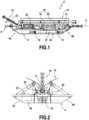
- FIGS 1 and 2 represent underwater equipment 2 according to the invention used for tensioning the anchor lines of such offshore structures.
- the equipment 2 includes in particular a rectangular platform 4 which is intended to rest on the seabed and to ensure the stability of the equipment when the anchor lines are tensioned and to ensure the self-alignment of the equipment.
- This platform 4 comprises two end flanks 4a, 4b connected to each other by two lateral flanks 4c, 4d, these flanks being inclined relative to the horizontal.
- the platform 4 is equipped with a passive ring 6 which is intended to be connected to a passive anchor line.
- the opposite end flank 4b called the “active end” of the equipment, defines a pulling axis 8 for the active anchor line 10.
- the platform is equipped with two high-capacity organs 12 (or rings on which a chain, a cable, etc. is moored), these organs being aligned on the pulling axis 8 and intended to be connected to a hauling winch of a surface installation vessel.
- the organs 12 are centered on the end flanks 4a, 4b, located in the lower part of the equipment and set back from the ends of the equipment. They thus define two hauling points for the deployment and recovery of the equipment from the surface installation vessel.
- the equipment according to the invention also comprises a V-shaped chute 14 which is mounted on the platform 4 extending between the passive end 4a and the active end 4b thereof.
- This chute 14 consists of two inclined plates forming a V open towards the surface when the equipment rests on the seabed. The function of this chute is to recover the active anchor line 10 to guide it towards the tensioning system.
- the tensioning system 16 of the active and passive anchor lines is positioned on the platform and under the chute 14. It notably comprises two locks - a mobile lock 18 and a fixed lock 20 - which are spaced from each other and which cooperate with the active anchor line 10 recovered by the chute according to an operating mode which will be described later.
- the movable lock 18 is coupled to hydraulic cylinders 21 for creating tension in the active anchor line.
- hydraulic cylinders 21 they are powered and controlled from the surface installation vessel via umbilicals described later.
- the passive end 4a of the equipment serves in particular to provide the reaction force to the anchor line tensioning system 16.
- a chain support chute 23 allows the active anchor line 10 to pass through the equipment lengthwise (from the active end 4b to the passive end 4a) by passing through the two locks 18, 20.
- the equipment according to the invention also comprises measuring instruments grouped within a housing 25 and known from the prior art for measuring in real time during the immersion, deployment and recovery of the equipment the trim, heel and azimuth angles of the equipment, as well as its immersion depth.
- the equipment according to the invention further comprises a system 22 for pre-tensioning the active anchor line once the latter is recovered by the chain support chute 23.
- This pre-tensioning system 22 is positioned under the V-shaped chute 14 downstream of the tensioning system 16. In particular, it makes it possible to apply tension in the passive and active anchor lines in order to minimize the duration of tensioning by the two locks 18, 20 of the tensioning system.
- the equipment according to the invention further comprises a system for locating the active anchor line (for example housed within the housing 25 grouping the measuring instruments) as it approaches the V-shaped chute 14 of the equipment.
- the active anchor line for example housed within the housing 25 grouping the measuring instruments
- this tracking system may be in the form of acoustic sensors (for example SONAR type or acoustic cameras) arranged in opposition on each plate of the V-shaped chute 14.
- the signals from these sensors are transmitted in real time to the surface installation vessel in order to enable it to know the relative position of the active anchor line with respect to said chute. This data then makes it possible to correct in real time from the surface installation vessel the position, tension and length of the active anchor line as it approaches the equipment.
- the equipment according to the invention further comprises at least one power and control umbilical which is intended to supply and control the tensioning system 16, jacks 21 and pre-tensioning system 22 as well as all the equipment for controlling the active and passive anchor lines.
- This power and control umbilical is advantageously housed in an umbilical basket 27 equipped with its release system and carried either by the port side or by the starboard side of the equipment. This basket provides structural protection during immersion and deployment of the equipment.
- This umbilical is capable of being deployed autonomously from the equipment and of being connected to the installation vessel once the equipment is placed on the seabed.
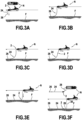
- FIG. 3A schematizes the initial conditions prior to starting the installation process.
- the passive anchor line 24 and its retaining anchor 26 are placed on the seabed F.
- the end of the passive anchor line opposite the anchor is connected to the passive ring 6 of the equipment 2.
- the active anchor line 10 it is either also placed on the seabed or is waiting on the deck of the installation vessel N.
- a length of abandonment chain is connected, on the one hand to the organs 12 of the equipment to allow the abandonment of the latter, and on the other hand to a hauling winch (not shown in the figures) of the installation vessel.
- the installation vessel N begins to advance in the opposite direction to the retaining anchor 26 of the passive anchor line 24. If necessary, port and starboard hooking lines can be installed on the equipment and be relieved or taken up to adjust the position of the equipment relative to the launching device of the installation vessel.
- the installation vessel N continues its course towards the equipment deployment position, gradually hauling out the abandonment chain in order to delicately launch the equipment ( Figure 3C ).
- the equipment is overflowed from the installation vessel and its overflow is controlled by the hauling winch.
- the descent of equipment 2 then continues by hauling the hauling winch and advancing the installation vessel N ( 3D figure ). During this descent, the equipment is suspended on the chain catenary between the installation vessel and the seabed.
- the installation vessel N continues on its azimuth away from the holding anchor 26 of the passive anchor line.
- the equipment gradually descends ( Figure 3E ).
- the progress of the equipment towards the seabed F is monitored in real time thanks to the acoustic transmission of measurement data (trim, heel and azimuth angles of the equipment, and immersion depth of the equipment) to the installation vessel.
- the installation vessel N stops and the operation of the hauling winch is stopped. The position of the equipment is checked against a predetermined position. The installation vessel N then completes its trajectory by abandoning the abandonment chain 28 which is connected to a surface buoy 30 ( Figure 3F ).
- the active anchor line is installed by the surface installation vessel in the V-shaped chute of the equipment to engage with the pre-tensioning and tensioning systems. This deployment of the active anchor line within the chute is carried out either directly from the installation vessel following the installation of the active anchor line or following its recovery by the installation vessel from the seabed where the active anchor line was lying awaiting deployment of the equipment. This recovery is controlled using the means described above.
- the power and control umbilical Prior to tensioning the active and passive anchor lines, the power and control umbilical is deployed from the equipment to be retrieved and connected to the installation vessel to power and control the tensioning system.
- the tensioning of the active and passive anchor lines by the equipment tensioning system is known per se. It is based on a back-and-forth movement formed by the two locks 18, 20 and the hydraulic cylinders 21.
- a pulling cycle comprises the following successive steps: the chain of the active anchor line is engaged in the equipment and rests in the chain support chute 23, the fixed lock 20 of the tensioning system 16 being open (i.e. in the low position) and the movable lock 18 being in the closed position (i.e. in the high position).
- the hydraulic cylinders 21 are retracted (i.e. in the start-of-stroke position).
- the hydraulic cylinders 21 are then deployed to their end-of-stroke position, which causes a movement of the movable lock 18 which drives the active anchor line over a length corresponding to the stroke length of the cylinders 21.
- the fixed lock 20 is then tilted into the closed position (high position) so as to block the active anchor line.
- the movable lock 18 it is tilted into the open position (low position) and thus releases the active anchor line.
- the hydraulic cylinders 21 can then be retracted to their start-of-stroke position so as to start a new pulling cycle.
- the active anchor line is kept under tension from the surface.
- the initial conditions for starting the installation process according to this embodiment variant are as follows: the retaining anchor of the active anchor line is placed on the seabed. The end of the active anchor line opposite the retaining anchor is kept on the surface on the deck of the installation vessel and installed and secured in the locks of the equipment tensioning system. As for the passive anchor line with its retaining anchor, they are waiting on the deck of the installation vessel.
- a length of abandonment chain is connected, on the one hand to the equipment organs on the passive end to allow it to be abandoned, and on the other hand to a hauling winch on the installation vessel.
- the installation vessel begins to move towards the intended position for dropping the passive anchor line retaining anchor. If necessary, port and starboard hooking lines can be installed on the equipment and can be eased or taken up to adjust the equipment's position relative to the installation vessel's launching device.
- the installation vessel continues its course towards the deployment position of the passive anchor line retaining anchor, gradually unhooking the abandonment chain in order to gently launch the equipment.
- the descent of the equipment is stopped after its immersion.
- the passive anchor line takes up the tension while the abandonment chain is relieved. The latter is secured to the passive anchor line.
- the descent of the equipment is then resumed by hauling the passive anchor line hauling winch and moving the installation vessel forward.
- the installation vessel continues its advance towards the position for dropping the passive anchor line retaining anchor while hauling the hauling winch.
- the progress of the equipment towards the seabed is monitored in real time thanks to the acoustic transmission of measurement data (trim, heel and azimuth angles of the equipment, and immersion depth of the equipment) to the installation vessel.
- the installation vessel stops and the hauling winch is stopped.
- the position of the equipment is checked against a predetermined position.
- the installation vessel then completes its trajectory by abandoning the passive anchor line and the passive anchor, which is connected to a surface buoy.
- the active anchor line is then ready to be tensioned.
- the power and control umbilicals Prior to tensioning the active and passive anchor lines, the power and control umbilicals are deployed from the equipment to be retrieved and connected to the installation vessel to power and control the tensioning system.
- the tensioning of the active and passive anchor lines by the equipment tensioning system can then begin according to the pulling cycle previously described with reference to the other embodiment of the installation process.
- this step of tensioning the active and passive anchor lines can advantageously be preceded by pre-tensioning using the pre-tensioning system 22 of the active anchor line.
- the active 10 and passive 24 anchor lines Prior to starting this recovery process, the active 10 and passive 24 anchor lines must be “de-tensioned” from the tensioning system of the equipment 2.
- the active anchor line 10 is extracted from the equipment 2 by hauling from the installation vessel N on the surface and deposited on the seabed F.
- the abandonment chain 28 is recovered and connected to the hauling winch of the installation vessel N, the latter being in the equipment recovery position ( Figure 4A ).
- the hauling winch of the installation vessel begins to regain tension on the abandonment chain 28.
- the installation vessel then advances towards the retaining anchor 26 of the passive anchor line 24 to allow the equipment 2 to be raised ( Figure 4B ).
- the installation vessel continues to move towards holding anchor 26, the hauling winch regaining tension to support the raising of the equipment ( Figure 4C ).
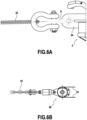
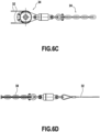
- the first step consists of connecting a first end of a multiplication cable 32 to the passive end 4a of the equipment 2, that is to say to the passive ring 6 thereof.
- the gearing cable 32 then passes through a first pulley 34 which is positioned on the passive end side of the equipment.
- the gearing cable is thus doubled on this side of the equipment (see Figure 6C ).
- the gearing cable 32 continues its path by passing towards the active end 4b of the equipment to pass through a second pulley 36 positioned on the side of the active end of the equipment (see Figure 6B ).
- the second end of the gearing cable 32 (opposite the first end) is then connected to a chain extension 38 which is itself connected to the tensioning system of the anchor lines of the equipment (see Figure 6D ).
- each pulley is connected to one of the active and passive anchor lines, namely here the first pulley 34 is connected to the passive anchor line 24, while the second pulley 36 is connected to the active anchor line 10.
Landscapes
- Engineering & Computer Science (AREA)
- Mechanical Engineering (AREA)
- Chemical & Material Sciences (AREA)
- Combustion & Propulsion (AREA)
- Ocean & Marine Engineering (AREA)
- Earth Drilling (AREA)
Claims (12)
- Unterwasserausrüstung (2) zum Spannen von Ankerleinen einer Offshore-Struktur, umfassend:- eine Plattform (4), die dazu bestimmt ist, auf einem Meeresboden (F) zu ruhen und die Stabilität der Ausrüstung und ihre Selbstausrichtung durch Gleiten auf dem Meeresboden beim Spannen der Ankerleinen zu gewährleisten, die Plattform umfassend ein passives Ende (4a), das mit einem passiven Ring (6) ausgerüstet ist, der dazu bestimmt ist, mit einer passiven Ankerleine (10) verbunden zu werden, die in einem Rückhalteanker endet, ein aktives Ende (4b) gegenüber dem passiven Ende und das eine Zugachse (8) definiert, und zwei Elemente (12), die entlang der Zugachse ausgerichtet sind, sich im unteren Teil der Plattform befinden und in Bezug auf die Enden zurückversetzt sind und geeignet sind, um ein Aussetzen von der Oberfläche bis zum Meeresboden und eine Bergung der Ausrüstung durch eine Schleppwinde eines Installationsschiffs (N) an der Oberfläche zu ermöglichen;- einen V-förmigen Kanal (14), der auf der Plattform (4) montiert ist, der sich zwischen dem passiven Ende und dem aktiven Ende der Plattform erstreckt, und der dazu bestimmt ist, eine aktive Ankerleine (10) einzuholen;- ein Spannsystem (16) der aktiven und der passiven Ankerleine, umfassend zwei Riegel (18, 20), die voneinander beabstandet sind und mit der aktiven Ankerleine zusammenwirken, die von dem Kanal eingeholt wird;- Einrichtungen zur Echtzeitmessung des Neigungs-, Krängungs- und Azimutwinkels der Ausrüstung sowie ihrer Eintauchtiefe während des Aussetzens und Einholens der Ausrüstung; und- akustische Kommunikationseinrichtungen, um die Messungen der Winkel und der Eintauchtiefe der Ausrüstung während ihrer Aussetzung und ihrer Einholung an das Installationsschiff zu übertragen.
- Ausrüstung nach Anspruch 1, ferner umfassend ein Vorspannsystem (22) der aktiven Ankerleine, sobald diese von dem Kanal (14) eingeholt wird.
- Ausrüstung nach einem der Ansprüche 1 und 2, ferner umfassend ein Ortungssystem der aktiven Ankerleine bei ihrer Annäherung an den Kanal.
- Ausrüstung nach einem der Ansprüche 1 bis 3, ferner umfassend eine Leistungs- und Steuerungsleitung zur Versorgung und Steuerung des Spannsystems der aktiven und der passiven Ankerleine, wobei die Leistungs- und Steuerungsleitung in einem Korb (27) untergebracht ist und geeignet ist, um autonom von der Ausrüstung ausgesetzt und mit dem Installationsschiff verbunden zu werden, nachdem die Ausrüstung auf dem Meeresboden abgesetzt wurde.
- Verfahren zur Installation einer Unterwasserausrüstung nach einem der Ansprüche 1 bis 4 zum Spannen von Ankerleinen einer Offshore-Struktur, das Installationsverfahren umfassend die folgenden aufeinanderfolgenden Schritte:- Absetzen des Rückhalteankers (26) der passiven Ankerleine (24) auf dem Meeresboden;- Verbinden auf dem Installationsschiff (N) der passiven Ankerleine (24) mit dem passiven Ring (6) der Ausrüstung;- Verbinden des Elements (12), das sich auf der Seite des aktiven Endes der Ausrüstung befindet, mit einer Aussetzkette (28), die mit der Schleppwinde des Installationsschiffs verbunden ist;- Absenken der Ausrüstung auf den Meeresboden durch Lösen der Winde und Vorwärtsbewegen des Installationsschiffs in entgegengesetzter Richtung zu dem Halteanker der passiven Ankerleine;- Absetzen der Ausrüstung (2) auf dem Meeresboden (F);- Anhalten des Installationsschiffs und Abkoppeln der Schleppwinde von der Aussetzkette;- Absetzen der aktiven Ankerleine (10) in dem Kanal der Ausrüstung;- Verlegen einer Leistungs- und Steuerungsleitung von der Ausrüstung, um eingeholt und mit dem Installationsschiff verbunden zu werden, um das Spannsystem (16) mit Strom zu versorgen und zu steuern; und- Aktivieren des Spannsystems (6) der aktiven und der passiven Ankerleine.
- Verfahren nach Anspruch 5, wobei die aktive Ankerleine anfangs auf dem Installationsschiff in Bereitschaft ist.
- Verfahren nach Anspruch 5, wobei die aktive Ankerleine anfangs auf dem Meeresboden in der Nähe der Stelle, an der die Ausrüstung abgesetzt wird, in Bereitschaft ist.
- Verfahren zur Installation einer Unterwasserausrüstung zum Spannen von Ankerleinen einer Offshore-Struktur nach einem der Ansprüche 1 bis 4, umfassend die folgenden aufeinanderfolgenden Schritte:- Absetzen eines Rückhalteankers der aktiven Ankerleine (10) auf dem Meeresboden (F);- Verriegeln und Sichern der aktiven Ankerleine (10) in dem Spannsystem (6) und dem Kettenhaltekanal (23) der Ausrüstung von der Oberfläche auf dem Deck des Installationsschiffs;- Verbinden, auf dem Installationsschiff (N), der passiven Ankerleine (24) und ihres Rückhalteankers (26) mit dem passiven Ring (6) der Ausrüstung;- Verbinden des Elements (12), das sich auf der Seite des passiven Endes der Ausrüstung befindet, mit einer Aussetzkette (28), die mit der Schleppwinde des Installationsschiffs verbunden ist;- Aussetzen und Absenken der Ausrüstung durch Lösen der Aussetzkette und Vorrücken des Installationsschiffs an die vorgesehene Position zum Aussetzen des Rückhalteankers der passiven Ankerleine;- Anhalten des Absetzens der Ausrüstung nach seinem Eintauchen in Wasser, wobei die passive Ankerleine die Spannung wieder aufnimmt, während die Aussetzkette geschockt und an der passiven Ankerleine gesichert wird;- Wiederaufnehmen des Absenkens der Ausrüstung auf den Meeresboden durch Lösen der passiven Ankerleine und Wiederaufnehmen der Vorwärtsfahrt des Installationsschiffes in Richtung der vorgesehenen Position zum Aussetzen des Rückhalteankers der passiven Ankerleine;- Absetzen der Ausrüstung auf dem Meeresboden;- Absetzen der passiven Ankerleine in Richtung der vorgesehenen Position des Ankers der passiven Ankerleine;- Absetzen des Rückhalteankers der passiven Ankerleine;- Verlegen der Leistungs- und Steuerungsleitung von der Ausrüstung, um eingeholt und mit dem Installationsschiff verbunden zu werden, um das Spannsystem mit Strom zu versorgen und zu steuern; und- Aktivieren des Spannsystems der aktiven und der passiven Ankerleine.
- Verfahren nach einem der Ansprüche 5 bis 8, wobei der Fortschritt der Ausrüstung (2) in Richtung Meeresboden (F) von dem Installationsschiff (N) durch Messungen des Neigungs-, Krängungs- und Azimutwinkels der Ausrüstung sowie der Eintauchtiefe kontinuierlich verfolgt wird.
- Verfahren nach einem der Ansprüche 5 bis 9, wobei die Aussetzkette (28), nachdem sie von der Schleppwinde getrennt wurde, auf dem Meeresboden gelagert und mit einer Oberflächenboje (30) verbunden wird.
- Verfahren nach einem der Ansprüche 5 bis 10, ferner umfassend das Einholen der Ausrüstung, umfassend die folgenden aufeinanderfolgenden:- Aktivieren des Spannsystems der aktiven und der passiven Ankerlinie, um diese zu entspannen;- Herausziehen der aktiven Ankerleine aus der Ausrüstung und Ablegen der Ankerleine auf dem Meeresboden;- Einholen und Verbinden der Aussetzkette mit der Schleppwinde des Installationsschiffs;- Verlagern des Installationsschiffs in Richtung des Rückhalteankers der passiven Ankerleine, um das Einholen der Ausrüstung zu ermöglichen; und- Einholen der Ausrüstung auf das Installationsschiff durch Ziehen der Schleppwinde.
- Verfahren nach einem der Ansprüche 5 bis 11, ferner umfassend die Untersetzung der Kraft zum Spannen der aktiven und der passiven Ankerleine, umfassend die folgenden aufeinanderfolgenden Schritte:- Verbinden eines ersten Endes eines Untersetzungskabels (32) mit dem passiven Ende (4a) der Ausrüstung;- Führen des Untersetzungskabels durch eine erste Rolle (34), die auf der Seite des passiven Endes der Ausrüstung positioniert ist;- Führen des Untersetzungskabels zu dem aktiven Ende (4b) der Ausrüstung durch eine zweite Rolle (36);- Verbinden eines zweiten Endes des Untersetzungskabels mit einer Kettenverlängerung (38), die mit dem Spannsystem (6) für die Ankerleinen der Ausrüstung verbunden ist;- Verbinden jeder Rolle (34, 36) mit einer von der aktiven und der passiven Ankerleine (10, 24); und- Ziehen, ausgeübt durch das Spannsystem der Ausrüstung auf die Kettenverlängerung (38).
Priority Applications (1)
| Application Number | Priority Date | Filing Date | Title |
|---|---|---|---|
| EP21305770.6A EP4101806B1 (de) | 2021-06-07 | 2021-06-07 | Unterwasserausrüstung zum spannen von ankerleinen einer offshore-struktur und verfahren zur installation einer solchen ausrüstung |
Applications Claiming Priority (1)
| Application Number | Priority Date | Filing Date | Title |
|---|---|---|---|
| EP21305770.6A EP4101806B1 (de) | 2021-06-07 | 2021-06-07 | Unterwasserausrüstung zum spannen von ankerleinen einer offshore-struktur und verfahren zur installation einer solchen ausrüstung |
Publications (3)
| Publication Number | Publication Date |
|---|---|
| EP4101806A1 EP4101806A1 (de) | 2022-12-14 |
| EP4101806C0 EP4101806C0 (de) | 2025-03-19 |
| EP4101806B1 true EP4101806B1 (de) | 2025-03-19 |
Family
ID=76483245
Family Applications (1)
| Application Number | Title | Priority Date | Filing Date |
|---|---|---|---|
| EP21305770.6A Active EP4101806B1 (de) | 2021-06-07 | 2021-06-07 | Unterwasserausrüstung zum spannen von ankerleinen einer offshore-struktur und verfahren zur installation einer solchen ausrüstung |
Country Status (1)
| Country | Link |
|---|---|
| EP (1) | EP4101806B1 (de) |
Family Cites Families (7)
| Publication number | Priority date | Publication date | Assignee | Title |
|---|---|---|---|---|
| US3845935A (en) | 1973-04-11 | 1974-11-05 | Hydranautics | Chain jack with mechanically and hydraulically operated pawls |
| US5934216A (en) | 1997-09-16 | 1999-08-10 | Oceaneering International Inc. | Method and apparatus for tensioning and deploying mooring chain |
| GB2551379B (en) * | 2016-06-16 | 2018-12-12 | Acergy France SAS | Upgrading subsea foundations of mooring systems |
| NO20170862A1 (en) * | 2017-05-24 | 2017-05-24 | Can Systems As | A mooring system |
| ES2956037T3 (es) * | 2018-03-02 | 2023-12-12 | Vicinay Mooring Connectors S A | Tensor de una línea de fondeo de una estructura flotante |
| NL2021529B1 (en) * | 2018-08-30 | 2020-04-30 | Stevlos Bv | Chain tensioner with chain switch device |
| GB201910603D0 (en) * | 2019-07-24 | 2019-09-04 | Subsea Riser Products Ltd | Mooring Line Tensioning Tool |
-
2021
- 2021-06-07 EP EP21305770.6A patent/EP4101806B1/de active Active
Also Published As
| Publication number | Publication date |
|---|---|
| EP4101806C0 (de) | 2025-03-19 |
| EP4101806A1 (de) | 2022-12-14 |
Similar Documents
| Publication | Publication Date | Title |
|---|---|---|
| US6983714B2 (en) | Method of and apparatus for offshore mooring | |
| US7507055B2 (en) | Apparatus and method for laying down, abandoning, and recovering a pipe on the sea floor | |
| EP2043911B1 (de) | Anlage und verfahren zur wiederherstellung eines unterwasser- oder wasserfahrzeugs | |
| EP2285663B1 (de) | System zum automatischen starten und zurückrufen einer unterwasserdrohne | |
| CN103781698B (zh) | 锚索张紧方法 | |
| US4445804A (en) | Method and apparatus for remote recovery of submerged pipelines | |
| FR2859495A1 (fr) | Methode d'installation et de connexion d'une conduite sous-marine montante | |
| FR2590539A1 (fr) | Systeme d'amarrage a cable unique, et procede de realisation d'un terminal de haute mer utilisant un tel systeme | |
| FR2531031A1 (fr) | Procede de descente au fond de l'ocean et de remontee en surface d'une station de recherches a de grandes profondeurs, et station mettant en application ledit procede | |
| EP2547938A1 (de) | Verfahren zum verlegen eines unterwasserkabels auf dem meeresgrund | |
| EP1318072A2 (de) | Verankerungssysteme | |
| EP3209546B1 (de) | System zum aussetzen und bergen von see- und unterseevorrichtungen mit unterstützung durch kippbare schutzkomponenten | |
| EP0522049B1 (de) | Verfahren zum verlegen von rohrförmigen leitungen | |
| EP0020257A1 (de) | Vorrichtung zum J-förmigen Verlegen einer Unterwasserrohrleitung | |
| EP0522050B1 (de) | Vorrichtung zum verlegen von rohrförmigen leitungen mit einer unter dem meeresspiegel liegenden klemme und verfahren unter zuhilfenahme dieser vorrichtung | |
| EP3906375B1 (de) | Verfahren zur verlegung und/oder rückgewinnung einer flexiblen leitung in einem gewässer und zugehöriges system | |
| EP4101806B1 (de) | Unterwasserausrüstung zum spannen von ankerleinen einer offshore-struktur und verfahren zur installation einer solchen ausrüstung | |
| CA2331176C (en) | Method and apparatus for suction anchor and mooring deployment and connection | |
| EP2621796B1 (de) | System mit einem unterwasserfahrzeug und einer basis an der oberfläche | |
| WO2013150079A1 (fr) | Procede de positionnement d'un ensemble de fond au fond d'une etendue d'eau, et dispositif associe | |
| EP0522059B1 (de) | Haltevorrichtung und verbindungsvorrichtung, die mit dieser haltevorrichtung ausgerüstet ist | |
| EP3987207B1 (de) | Verfahren zum verlegen und/oder zurückholen einer leitung in einem gewässer, mit einer phase der gesteuerten immobilisierung | |
| FR3132076A1 (fr) | Procédé d'exploration sous-marine et dispositif de mouillage d'un drone d'exploration sous-marine | |
| FR2638417A1 (fr) | Procede et dispositif de recuperation d'un corps flottant a l'aide d'une grue |
Legal Events
| Date | Code | Title | Description |
|---|---|---|---|
| PUAI | Public reference made under article 153(3) epc to a published international application that has entered the european phase |
Free format text: ORIGINAL CODE: 0009012 |
|
| STAA | Information on the status of an ep patent application or granted ep patent |
Free format text: STATUS: THE APPLICATION HAS BEEN PUBLISHED |
|
| AK | Designated contracting states |
Kind code of ref document: A1 Designated state(s): AL AT BE BG CH CY CZ DE DK EE ES FI FR GB GR HR HU IE IS IT LI LT LU LV MC MK MT NL NO PL PT RO RS SE SI SK SM TR |
|
| STAA | Information on the status of an ep patent application or granted ep patent |
Free format text: STATUS: REQUEST FOR EXAMINATION WAS MADE |
|
| 17P | Request for examination filed |
Effective date: 20230609 |
|
| RBV | Designated contracting states (corrected) |
Designated state(s): AL AT BE BG CH CY CZ DE DK EE ES FI FR GB GR HR HU IE IS IT LI LT LU LV MC MK MT NL NO PL PT RO RS SE SI SK SM TR |
|
| GRAP | Despatch of communication of intention to grant a patent |
Free format text: ORIGINAL CODE: EPIDOSNIGR1 |
|
| STAA | Information on the status of an ep patent application or granted ep patent |
Free format text: STATUS: GRANT OF PATENT IS INTENDED |
|
| RIC1 | Information provided on ipc code assigned before grant |
Ipc: B63B 21/50 20060101ALN20240925BHEP Ipc: B63B 21/00 20060101ALN20240925BHEP Ipc: B63B 21/18 20060101ALI20240925BHEP Ipc: B63B 21/04 20060101ALI20240925BHEP Ipc: B66D 3/00 20060101AFI20240925BHEP |
|
| INTG | Intention to grant announced |
Effective date: 20241021 |
|
| GRAS | Grant fee paid |
Free format text: ORIGINAL CODE: EPIDOSNIGR3 |
|
| GRAA | (expected) grant |
Free format text: ORIGINAL CODE: 0009210 |
|
| STAA | Information on the status of an ep patent application or granted ep patent |
Free format text: STATUS: THE PATENT HAS BEEN GRANTED |
|
| RAP1 | Party data changed (applicant data changed or rights of an application transferred) |
Owner name: VINCI CONSTRUCTION GRANDS PROJETS |
|
| AK | Designated contracting states |
Kind code of ref document: B1 Designated state(s): AL AT BE BG CH CY CZ DE DK EE ES FI FR GB GR HR HU IE IS IT LI LT LU LV MC MK MT NL NO PL PT RO RS SE SI SK SM TR |
|
| REG | Reference to a national code |
Ref country code: GB Ref legal event code: FG4D Free format text: NOT ENGLISH |
|
| REG | Reference to a national code |
Ref country code: CH Ref legal event code: EP |
|
| REG | Reference to a national code |
Ref country code: IE Ref legal event code: FG4D Free format text: LANGUAGE OF EP DOCUMENT: FRENCH |
|
| REG | Reference to a national code |
Ref country code: DE Ref legal event code: R096 Ref document number: 602021027770 Country of ref document: DE |
|
| U01 | Request for unitary effect filed |
Effective date: 20250416 |
|
| U07 | Unitary effect registered |
Designated state(s): AT BE BG DE DK EE FI FR IT LT LU LV MT NL PT RO SE SI Effective date: 20250424 |
|
| U20 | Renewal fee for the european patent with unitary effect paid |
Year of fee payment: 5 Effective date: 20250502 |
|
| PG25 | Lapsed in a contracting state [announced via postgrant information from national office to epo] |
Ref country code: RS Free format text: LAPSE BECAUSE OF FAILURE TO SUBMIT A TRANSLATION OF THE DESCRIPTION OR TO PAY THE FEE WITHIN THE PRESCRIBED TIME-LIMIT Effective date: 20250619 |
|
| PGFP | Annual fee paid to national office [announced via postgrant information from national office to epo] |
Ref country code: GB Payment date: 20250625 Year of fee payment: 5 |
|
| PGFP | Annual fee paid to national office [announced via postgrant information from national office to epo] |
Ref country code: NO Payment date: 20250530 Year of fee payment: 5 |
|
| PG25 | Lapsed in a contracting state [announced via postgrant information from national office to epo] |
Ref country code: HR Free format text: LAPSE BECAUSE OF FAILURE TO SUBMIT A TRANSLATION OF THE DESCRIPTION OR TO PAY THE FEE WITHIN THE PRESCRIBED TIME-LIMIT Effective date: 20250319 |
|
| PG25 | Lapsed in a contracting state [announced via postgrant information from national office to epo] |
Ref country code: GR Free format text: LAPSE BECAUSE OF FAILURE TO SUBMIT A TRANSLATION OF THE DESCRIPTION OR TO PAY THE FEE WITHIN THE PRESCRIBED TIME-LIMIT Effective date: 20250620 |
|
| PGFP | Annual fee paid to national office [announced via postgrant information from national office to epo] |
Ref country code: IE Payment date: 20250521 Year of fee payment: 5 |
|
| PG25 | Lapsed in a contracting state [announced via postgrant information from national office to epo] |
Ref country code: SM Free format text: LAPSE BECAUSE OF FAILURE TO SUBMIT A TRANSLATION OF THE DESCRIPTION OR TO PAY THE FEE WITHIN THE PRESCRIBED TIME-LIMIT Effective date: 20250319 |
|
| PG25 | Lapsed in a contracting state [announced via postgrant information from national office to epo] |
Ref country code: ES Free format text: LAPSE BECAUSE OF FAILURE TO SUBMIT A TRANSLATION OF THE DESCRIPTION OR TO PAY THE FEE WITHIN THE PRESCRIBED TIME-LIMIT Effective date: 20250319 |
|
| PG25 | Lapsed in a contracting state [announced via postgrant information from national office to epo] |
Ref country code: PL Free format text: LAPSE BECAUSE OF FAILURE TO SUBMIT A TRANSLATION OF THE DESCRIPTION OR TO PAY THE FEE WITHIN THE PRESCRIBED TIME-LIMIT Effective date: 20250319 |
|
| PG25 | Lapsed in a contracting state [announced via postgrant information from national office to epo] |
Ref country code: CZ Free format text: LAPSE BECAUSE OF FAILURE TO SUBMIT A TRANSLATION OF THE DESCRIPTION OR TO PAY THE FEE WITHIN THE PRESCRIBED TIME-LIMIT Effective date: 20250319 |
|
| PG25 | Lapsed in a contracting state [announced via postgrant information from national office to epo] |
Ref country code: SK Free format text: LAPSE BECAUSE OF FAILURE TO SUBMIT A TRANSLATION OF THE DESCRIPTION OR TO PAY THE FEE WITHIN THE PRESCRIBED TIME-LIMIT Effective date: 20250319 |
|
| PG25 | Lapsed in a contracting state [announced via postgrant information from national office to epo] |
Ref country code: IS Free format text: LAPSE BECAUSE OF FAILURE TO SUBMIT A TRANSLATION OF THE DESCRIPTION OR TO PAY THE FEE WITHIN THE PRESCRIBED TIME-LIMIT Effective date: 20250719 |
|
| PLBE | No opposition filed within time limit |
Free format text: ORIGINAL CODE: 0009261 |
|
| STAA | Information on the status of an ep patent application or granted ep patent |
Free format text: STATUS: NO OPPOSITION FILED WITHIN TIME LIMIT |
|
| REG | Reference to a national code |
Ref country code: CH Ref legal event code: H13 Free format text: ST27 STATUS EVENT CODE: U-0-0-H10-H13 (AS PROVIDED BY THE NATIONAL OFFICE) Effective date: 20260127 |
|
| REG | Reference to a national code |
Ref country code: CH Ref legal event code: L10 Free format text: ST27 STATUS EVENT CODE: U-0-0-L10-L00 (AS PROVIDED BY THE NATIONAL OFFICE) Effective date: 20260128 |
|
| PG25 | Lapsed in a contracting state [announced via postgrant information from national office to epo] |
Ref country code: MC Free format text: LAPSE BECAUSE OF FAILURE TO SUBMIT A TRANSLATION OF THE DESCRIPTION OR TO PAY THE FEE WITHIN THE PRESCRIBED TIME-LIMIT Effective date: 20250319 |
|
| 26N | No opposition filed |
Effective date: 20251222 |