EP3987207B1 - Verfahren zum verlegen und/oder zurückholen einer leitung in einem gewässer, mit einer phase der gesteuerten immobilisierung - Google Patents
Verfahren zum verlegen und/oder zurückholen einer leitung in einem gewässer, mit einer phase der gesteuerten immobilisierung Download PDFInfo
- Publication number
- EP3987207B1 EP3987207B1 EP20734032.4A EP20734032A EP3987207B1 EP 3987207 B1 EP3987207 B1 EP 3987207B1 EP 20734032 A EP20734032 A EP 20734032A EP 3987207 B1 EP3987207 B1 EP 3987207B1
- Authority
- EP
- European Patent Office
- Prior art keywords
- line
- successive
- gripping members
- change
- stop position
- Prior art date
- Legal status (The legal status is an assumption and is not a legal conclusion. Google has not performed a legal analysis and makes no representation as to the accuracy of the status listed.)
- Active
Links
Images


Classifications
-
- F—MECHANICAL ENGINEERING; LIGHTING; HEATING; WEAPONS; BLASTING
- F16—ENGINEERING ELEMENTS AND UNITS; GENERAL MEASURES FOR PRODUCING AND MAINTAINING EFFECTIVE FUNCTIONING OF MACHINES OR INSTALLATIONS; THERMAL INSULATION IN GENERAL
- F16L—PIPES; JOINTS OR FITTINGS FOR PIPES; SUPPORTS FOR PIPES, CABLES OR PROTECTIVE TUBING; MEANS FOR THERMAL INSULATION IN GENERAL
- F16L1/00—Laying or reclaiming pipes; Repairing or joining pipes on or under water
- F16L1/12—Laying or reclaiming pipes on or under water
- F16L1/14—Laying or reclaiming pipes on or under water between the surface and the bottom
- F16L1/15—Laying or reclaiming pipes on or under water between the surface and the bottom vertically
-
- F—MECHANICAL ENGINEERING; LIGHTING; HEATING; WEAPONS; BLASTING
- F16—ENGINEERING ELEMENTS AND UNITS; GENERAL MEASURES FOR PRODUCING AND MAINTAINING EFFECTIVE FUNCTIONING OF MACHINES OR INSTALLATIONS; THERMAL INSULATION IN GENERAL
- F16L—PIPES; JOINTS OR FITTINGS FOR PIPES; SUPPORTS FOR PIPES, CABLES OR PROTECTIVE TUBING; MEANS FOR THERMAL INSULATION IN GENERAL
- F16L1/00—Laying or reclaiming pipes; Repairing or joining pipes on or under water
- F16L1/12—Laying or reclaiming pipes on or under water
- F16L1/20—Accessories therefor, e.g. floats or weights
- F16L1/23—Pipe tensioning apparatus
-
- F—MECHANICAL ENGINEERING; LIGHTING; HEATING; WEAPONS; BLASTING
- F16—ENGINEERING ELEMENTS AND UNITS; GENERAL MEASURES FOR PRODUCING AND MAINTAINING EFFECTIVE FUNCTIONING OF MACHINES OR INSTALLATIONS; THERMAL INSULATION IN GENERAL
- F16L—PIPES; JOINTS OR FITTINGS FOR PIPES; SUPPORTS FOR PIPES, CABLES OR PROTECTIVE TUBING; MEANS FOR THERMAL INSULATION IN GENERAL
- F16L1/00—Laying or reclaiming pipes; Repairing or joining pipes on or under water
- F16L1/12—Laying or reclaiming pipes on or under water
- F16L1/16—Laying or reclaiming pipes on or under water on the bottom
- F16L1/18—Laying or reclaiming pipes on or under water on the bottom the pipes being S- or J-shaped and under tension during laying
- F16L1/19—Laying or reclaiming pipes on or under water on the bottom the pipes being S- or J-shaped and under tension during laying the pipes being J-shaped
Definitions
- the present invention relates to a method of laying and/or recovering a line in a body of water, according to the preamble of claim 1.
- WO2015/069099 WO2011/141793 And WO2007/108673 describe methods of laying lines in a body of water.
- the line is for example a flexible line, in particular a flexible pipe as described in the normative documents published by the American Petroleum Institute (API), API 17J “Specification for Unbonded Flexible Pipe” 4th Edition May 2014, and API RP 17B “ Recommended Practice for Flexible Pipe » 5th Edition May 2014.
- Flexible pipe is for example a rising pipe (or “riser” in English) and/or a pipe placed on the seabed (or “flowline” in English).
- the flexible pipe is a composite bundle of the "bundle" type, comprising at least one fluid transport tube and a set of electrical or optical cables capable of transporting electrical or hydraulic power or information between the bottom and the surface of the body of water.
- the flexible line is a submarine umbilical described in the API 17E normative document, or an electrical power cable.
- the line installed or recovered by the process is a rigid pipe as described in the normative document published by the Det Norske Veritas and Germanischer Lloyd (DNV-GL), DNVGL-ST-F101 “Submarine pipeline systems” Edition 2017 .
- the storage means include a basket or a rotating drum.
- the line is unrolled from the storage means, then is generally reassembled on a chute carried by the tower of the laying device.
- the line is engaged in gripping and moving assemblies comprising tracked gripping members.
- the line thus descends vertically or inclined along the tower, before plunging into the body of water.
- the line is held by the opposite gripping devices which ensure its suspension in the body of water.
- the opposite gripping members support the mechanical tension coming from the weight of the unrolled line and avoid the storage means to undergo this weight, while guaranteeing that the line does not undergo bending which goes beyond its minimum radius of curvature in bending without damage (“MBR” or “Minimal Bending Radius” in English).
- a vertical well is generally provided through the hull of the vessel to form a passage for lowering the line.
- Such a well is referred to by the English term “moon pool”.
- the tower of the laying device extends vertically or inclined in the vicinity of this well to allow the deployment of the line through the passage.
- the installation device tower is located at the rear of the hull.
- the installation device comprises, from top to bottom on the tower, at least a first group of upper gripping members and a second group of lower gripping members.
- the line is laid horizontally with gripping members arranged in tandem.
- These operations include, for example, the installation of buoys around the line at regular intervals, to give it a wave-shaped configuration.
- Other operations include one-off repairs on the line, or even underwater operations related to the line, for example connections/disconnections, interventions by remotely piloted underwater vehicles.
- the stopping of the installation can also result from a hold, linked for example to the weather and/or to constraints imposed by neighboring oil installations.
- the gripping devices are equipped with mechanical brake systems which block the axis of at least one motor, on command from the control unit. Then, when the installation can restart, the control unit deactivates the mechanical brakes and reactivates the gripping devices.
- the lower and upper parts of the gripping members undergo, just after immobilization of the line, a relatively high downward stress which results from the stabilization of the line on the gripping member. (referred to by the English term “pad landing” or “pad take off”). This constraint opposes the retention of the line by the input device.
- the aforementioned phenomenon can prove problematic when the hanging weight carried by the gripping members approaches the nominal holding capacity of the gripping members. In this case, the retention of the line may prove insufficient, which could lead, in critical cases, to an uncontrolled fall of the line into the body of water.
- An aim of the invention is therefore to provide a method of laying and/or raising a flexible line which makes it possible to ensure the installation of a flexible line in complete safety, without causing a significant reduction in the installation capacity. .
- the subject of the invention is a method according to claim 1.
- the method according to the invention may comprise one or more of the characteristics of claims 2 to 8, taken in isolation or in any technically possible combination.
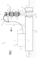
- a first system 10 for laying and/or recovering a line 12 is shown on the Figures 1 to 3 .
- the system 10 floats on a body of water 11 (visible on the Figure 1 ) which is for example a sea, an ocean or a lake.
- the depth of the body of water 11 between the surface 11A and the bottom is greater than 5 meters, and is in particular between 100 meters and 4000 meters.
- the installation system 10 is intended for the installation and/or recovery of a line 12 which is advantageously a flexible line, in particular a flexible pipe.
- Flexible pipe is in particular pipe as described in the normative documents published by the American Petroleum Institute (API), API 17J, and API RP17B.
- the pipe is alternatively an umbilical as described in the normative documents published by the American Petroleum Institute (API), API17E or even a rigid unrolled pipe as described in the normative document published by the Det Norske Veritas et Germanischer Lloyd (DNV-GL), DNVGL-ST-F101 Edition 2017 .
- This definition indifferently includes flexible pipes of the unbonded or bonded type.
- the flexible line 12 is a composite bundle of the "bundle" type comprising at least one fluid transport tube and a set of electrical or optical cables capable of transporting electrical or hydraulic power or information between the bottom and surface of the body of water.
- the flexible line 12 is a submarine umbilical described in the normative document API 17E, or an electrical power cable.
- line 12 is a rigid pipe described in the normative document DNVGL-ST-F101.
- Line 12 may carry equipment, such as buoys, connectors or bottom equipment which have a transverse extent greater than its average transverse extent.
- the installation and/or recovery system 10 comprises a hull 14 floating on the body of water 11, and an assembly 16 for storing the line 12 on the hull 14.
- It comprises an installation and/or recovery device 18 and a control unit 19, mounted on the hull 14.
- the hull 14 is for example the hull of a ship comprising propulsion means.
- the hull 14 is formed by a platform floating on the body of water 11, a barge, or a semi-submersible barge.
- the hull 14 extends between a lower surface 22 immersed under the body of water 11 and an upper deck 24, from which the installation and/or recovery device 18 projects.
- the bridge 24 is advantageously located above the surface 11A of the body of water 11.
- the hull 14 internally delimits, between the lower surface 22 and the upper surface 24, a central through well 26, visible on there figure 1 .
- the central well 26 extends vertically. It opens upwards onto the bridge 24 and it opens downwards into the body of water 11 through the lower surface 22.
- the storage assembly 16 is formed by a rotating member 28 for storing the pipe in a wound configuration.
- the rotating member 28 is for example a drum with a horizontal axis of rotation or a basket with a vertical axis of rotation.
- the storage assembly 16 is arranged on the deck 24 or in the hull 14.
- the rotation of the storage member 28 in a first direction around its axis A-A' allows the unfolding of an increasing length of line 12 towards the laying device 18, while the rotation in a second direction opposite to the first direction allows winding an increasing length of pipe on the storage member 28.
- the installation device 18 comprises a tower 30 of vertical axis B-B', defining a tower axis, at least one upper assembly 34 for gripping and moving the line 12, and at least one assembly lower 35 for gripping and moving line 12, the assemblies 34, 35 being carried by the tower 30.
- the installation device 18 further comprises an assembly 36 for guiding the movement of the line 12 between the storage assembly 16 and the gripping and movement assemblies 34, 35.
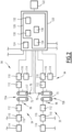
- Each assembly 34, 35 comprises a support frame 70 and at least two tracked gripping members 72A, 72B, for example between two and six gripping members 72A, 72B, carried by the chassis 70.
- Each assembly 34, 35 further comprises a sensor 76 for measuring information representative of the load applied by the line 12 on the input member 72A, 72B (visible on the figure 2 ).
- Each chassis 70 is suitable for being moved between an open configuration for placing line 12 in the chassis and a closed configuration for use.
- each frame 70 delimits a central passage 73 extending vertically along an axis CC' defining an installation axis of the line 12.
- This installation axis CC' is substantially parallel to the axis BB' of the tower 30 , that is to say totally parallel or inclined at an angle less than, for example, 10° relative to the axis B-B'.
- each frame 70 advantageously carries two gripping members 72A, 72B arranged substantially parallel to each other
- Each gripping member 72A, 72B projects into the passage 73 towards the axis C-C'.
- the gripping member 72A, 72B comprises a movement member 90, formed by a guide caterpillar intended to grasp and move the line 12, two toothed wheels 92, on which the movement member 90 is wound, a device 94 d 'drive of the movement member 90 along the axis B-B', and a mechanism 96 for radial movement of each movement member 90 towards the axis B-B'.
- the displacement member 90 has substantially the shape of an endless strip wound on two toothed wheels 92. It thus has a longitudinal part 98A for guiding the pipe and a longitudinal return part 98B, intended to extend parallel to the axis C-C' of installation.
- the displacement member 90 here comprises a plurality of pads mounted end to end to form the endless belt.
- the guide part 98A is intended to come into contact with the outer peripheral surface of the line 12, along a generator.
- the opposite guide sections 98A of two facing gripping members 72 face each other and are capable of respectively gripping two opposite angular sections of the line 12 relative to the axis C-C'.
- the toothed wheels 92 are movable in rotation around an axis perpendicular to the axis C-C'. They are rotated around their axis by the device 94, to cause the parts 98A, 98B to move parallel to the axis C-C'.
- each drive device 94 comprises a motor 110, controllable by the control unit 19, advantageously a reduction motor 112, connecting the motor 110 to at least one toothed wheel 92 and a mechanical brake 114 for blocking the motor 110.
- the drive device 94 advantageously comprises a sensor 116 for measuring the torque applied by each motor 110, and/or a sensor 117 for measuring the speed of movement of the line 12.
- the motor 110 is for example a hydraulic motor or an electric motor. It is able to generate a variable torque depending on the desired configuration.
- the variable torque is chosen from a retaining torque of line 12 in a stationary configuration of line 12, and a displacement torque of line 12 through the central passage 73 in a displacement configuration of line 12.
- the mechanical brake 114 can also be controlled by the control unit 19 between a disengaged position, in which the motor 110 is free to rotate the toothed wheels 92 and an engaged position in which it is capable of immobilizing the motor 110 and /or each toothed wheel 92 to statically retain line 12, even in the absence of torque applied by motor 110.
- the radial movement mechanism 96 comprises for example at least one cylinder capable of moving each movement member 90 radially towards the installation axis C-C', in order to apply a determined force on the outer peripheral surface of the line 12.
- the control unit 19 is shown schematically on the figures 1 And 2 . It includes, for example, a computer 120 and a man-machine interface 122.
- the computer 120 comprises a processor 124 and a memory 126 capable of containing functional software modules intended to be executed by the computer 124.
- the functional modules are produced at least partially in the form of programmable logic components, or even in the form of dedicated integrated circuits.
- the memory 126 contains a module 130 for selective activation of each motor 110, a module 132 for regulating each motor 110 in speed or torque, connected to each sensor 116, 117, and advantageously, a module 134 d activation of the mechanical brake 114.
- It contains a module 136 for controlling modules 130, 132, 134 between a rest configuration, an installation and/or recovery configuration of line 12, and an immobilization configuration of line 12.
- the activation module 130 deactivates each motor 110 and the activation module 134 activates at least one mechanical brake 114.
- the activation module 134 deactivates each mechanical brake 114.
- the activation module 130 activates each motor 110 and the regulation module 132 controls each motor 110 in torque, and/or in speed on the basis of information received from at least one sensor 116, 117 to achieve an installation and/or recovery speed, greater than 2 m/hour, in particular between 2 m/hour and 2000 m/hour.
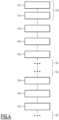
- the control module 136 is capable of controlling the regulation module 132 of each motor 110 to carry out an overtaking limited 158 from the immobilization position downwards, in order to reach a position of change of direction of movement, then to carry out a delay 160 in the position of change of direction of movement, in which the line 12 remains temporarily stationary, before carrying out a limited rise 162 of line 12 from the position of change of direction of movement towards the immobilization position.
- the limited overhang 158 is preferably at least 0.5 m.
- the limited overhang 158 is advantageously at most 10 m, for example at most 7 m, in particular at most 3 m, in particular at most 1 m. This overrun is generally between 0.5 m and 1 m.
- the time delay 160 carried out in the position of change of direction of movement, in which line 12 remains stationary preferably lasts at least 0.5 seconds.
- the delay 160 carried out in the position of change of direction of movement advantageously lasts at most 60 seconds, preferably at most 40 seconds, in particular at most 10 seconds and is generally between 1 second and 5 seconds.
- control module 136 is capable of carrying out the steps 158, 160, 162 previously described for a plurality of successive immobilizations of line 12 in successive immobilization positions.
- the method comprises, before each successive immobilization, the steps of limited overtaking of each successive immobilization position downwards to reach a successive position of change of direction of movement, the time delay in each position of change of direction of movement. successive movement, and the limited rise of line 12 from each successive change of direction of movement position to the successive stop position.
- Steps 158, 160, 162 are preferably implemented for any immobilization of line 12 occurring when the hanging weight of line 12 under the gripping members 72A, 72B is greater than 50% of the maximum holding capacity of the lines. gripping members 72A, 72B, with maximum radial tightening adjustment of the facing gripping members 72A, 72B.
- steps 158, 160, 162 are not implemented for any immobilization of line 12 occurring between the start of installation and the moment when the hanging weight reaches 50% of the maximum capacity.
- control module 136 controls the modules 132 and 134 to carry out a succession of intervals of holding line 12 stationary, in which the motors 110 of at least one upper gripping member 72A and of at least a lower gripping member 72B applies a restraining torque on the line 12 without moving a retaining member 90 and load regulation intervals in which a motor 110 of an upper gripping member 72A or a member upper gripping member 72B is active to generate a limited movement of a movement member 90 of a lower gripping member 72A and/or an upper gripping member 72B or a modification of the holding torque applied to a movement member 90 of a lower gripping member 72A and/or an upper gripping member 72B.
- control module 136 regularly measures information representative of a difference between the load applied to at least one upper gripping member 72A and the load applied to at least one lower gripping member 72B using sensors 76 , and moves a moving member 90 of the lower gripping members 72B and/or the upper gripping members 72A by the motor 110, or modifies the torque applied to a moving member 90 of the lower gripping members 72B and/or the members upper input 72A by the motor 110 as a function of the representative information measured.
- the control module 136 activates the motor 110 of a lower gripping member 72B to move a movement member 90 of the lower gripping members 72B or modify the restraining torque applied to the movement member 90 of the lower gripping members 72B until the measured load difference is less than or equal to the predetermined threshold.
- the man-machine interface 122 comprises for example a control member, in particular a joystick and/or a touch screen, and a display to allow the control unit 19 to switch between the rest configuration, the installation configuration or / and recovery, and the immobilization configuration of line 12. It is suitable for allowing the user to select a speed of installation and/or recovery of line 12 in the installation and/or recovery configuration .
- the guide assembly 34 comprises at least one curved guide chute 140 or a wheel arranged above the tower 30 to redirect the line 12 taken from the storage assembly 16 in the axis of the tower 30.
- the chute 140 has substantially a U shape facing downwards defining an adequate radius of curvature for line 12. This radius of curvature is greater than the minimum radius of curvature (MBR) of line 12.
- the line 12 is stored in the storage assembly 16 by being wound on the rotating member 28.
- Line 12 thus maintains an adequate radius of curvature greater than its MBR.
- the system 10 is then moved over the body of water 11 to a laying region in which the line 12 must be deployed.
- the respective frames 70 of the gripping and movement assemblies 34, 35 are open at least partially.
- One end of line 12 is then brought into contact with the chute 140 by engaging it thereon.
- the radial movement mechanisms 96 of the movement members 90 are then activated to apply each longitudinal guide part 98A against the outer peripheral surface of the line 12 along a generatrix thereof.
- the radial movement mechanisms 96 are also controlled to apply a predetermined pressure on line 12.
- an installation phase 150 is then carried out.
- the control unit 19 switches to its installation configuration. It activates the motors 110 in step 152, and controls the motors in step 154 to develop a displacement torque of the displacement member 90. This generates a continuous downward movement of the line 12 through the passages circulation 73, regulated at a speed of movement greater than 2 m/hour, in particular between 2 m/hour and 2000 m/hour.
- the device 94 for driving the toothed wheels 92 in rotation is activated.
- the displacement members 90 are driven in movement, so that each longitudinal part 98A moves up and down driving the line 12.
- the line 12 is thus driven in translation downwards along the installation axis C-C' by the movement members 90 of the gripping members 72A, 72B facing each assembly 34, 35.
- an immobilization phase 156 in an immobilized position is then implemented.
- control module 136 commands the regulation module 132 to carry out a limited overshoot 158 of the immobilization position downwards to reach a position change of direction of movement.
- this limited overhang is preferably at least 0.5 m.
- the limited overhang 158 is advantageously at most 10 m, for example at most 7 m, in particular at most 3 m, in particular at most 1 m. This overrun is generally between 0.5 m and 1 m.
- a time delay 160 is carried out in the position of change of direction of movement. During this delay, line 12 temporarily stops in the position for changing direction of movement.
- the time delay 160 carried out in the position of change of direction of movement, in which line 12 remains stationary preferably lasts at least 0.5 seconds.
- the delay 160 carried out in the position of change of direction of movement advantageously lasts at most 60 seconds, preferably at most 40 seconds, in particular at most 10 seconds and is generally between 1 second and 5 seconds.
- the method includes a limited rise 162 of line 12 from the position of change of direction of movement towards the immobilization position. This ascent is carried out over the aforementioned overtaking distance and line 12 is then immobilized in the immobilization position.
- the axial load applied by a series of pads applying to the bottom of each gripping member 72A, 72B, and in particular on the lower gripping member 72B at the time of stopping of line 12 (end of the step 158) in the position for changing direction of movement is important. This axial load is directed downwards.
- the limited rise 162 of the line to the immobilization position results in a total reversal of the direction of the load applying to the gripping members 72A, 72B when they are definitively immobilized in the immobilization position.
- line 12 is stably immobilized in the gripping members 72A, 72B, which avoids the undesired phenomena described above.
- the gripping members 72A, 72B do not have to be oversized and can be used for a greater installation capacity, increasing the mass of the line 12 which can be installed using the installation system 10 according to the 'invention.
- a stabilization process as described in the patent application FR 18 74403 is implemented to reduce the load difference that can be observed between the upper gripping member 72A and the lower gripping member 72B.
- line 12 is recovered using system 10 according to the invention.
- the control module 136 is able to control the regulation module 132 to carry out a limited overshoot of the immobilization position upwards to reach a position change of direction of movement, then a delay in the change of direction of movement position, before a limited descent of line 12 from the position of change of direction of movement to the immobilization position.
- the limited overhang 158 is preferably at least 0.5 m.
- the limited overhang 158 is advantageously at most 10 m, for example at most 7 m, in particular at most 3 m, in particular at most 1 m. This overrun is generally between 0.5 m and 1 m.
- the time delay 160 carried out in the position of change of direction of movement, in which line 12 remains stationary preferably lasts at least 0.5 seconds.
- the delay 160 carried out in the position of change of direction of movement advantageously lasts at most 60 seconds, preferably at most 40 seconds, in particular at most 10 seconds and is generally between 1 second and 5 seconds.
- the upper gripping members 72A are located above the lower gripping members 72B.
- the gripping members 72A are therefore upstream gripping members 72A, and the gripping members 72B are downstream gripping members 72B relative to the direction of movement of the line.
- the upstream gripping members 72A are not necessarily positioned above the downstream gripping members 72B.
Landscapes
- Engineering & Computer Science (AREA)
- General Engineering & Computer Science (AREA)
- Mechanical Engineering (AREA)
- Earth Drilling (AREA)
- Pipeline Systems (AREA)
- Physical Or Chemical Processes And Apparatus (AREA)
- Load-Engaging Elements For Cranes (AREA)
Claims (8)
- Verfahren zum Verlegen oder/und Einholen einer Leitung (12) in einem Gewässer (11), welches die folgenden Schritte umfasst:- Bereitstellung einer Verlegevorrichtung (18), die mindestens zwei gegenüberliegende stromaufwärtige Greiforgane (72A) und mindestens zwei gegenüberliegende stromabwärtige Greiforgane (72B) umfasst, wobei die gegenüberliegenden Greiforgane (72A; 72B) einen Durchgang (73) für den Umlauf der Leitung (12) definieren, in dem die Leitung (12) lokal eingeklemmt ist; wobei jedes Greiforgan (72A; 72B) ein Organ (90) zum Verschieben der Leitung (12) umfasst und mindestens einen Motor (110) zum Bewegen des Verschiebungsorgans (90), der aktiviert werden kann, um ein Drehmoment zum Verschieben der Leitung (12) zu erzeugen, wobei die Verlegevorrichtung (18) eine Steuereinheit (19) für jeden Motor (110) umfasst, wobei das Verfahren die folgenden Schritte umfasst:- Absenken der Leitung (12) in aufeinanderfolgende Immobilisierungpositionen;- sukzessive Immobilisierung der Leitung (12) in jeder Position der sukzessiven Immobilisierung;gekennzeichnet durch die folgenden Schritte, die vor jeder sukzessiven Immobilisierung der Leitung in einer Position der sukzessiven Immobilisierung durchgeführt werden:- begrenztes Überschreiten von mindestens 0,5 m aus der Position der sukzessiven Immobilisierung nach unten, um eine Position für den sukzessiven Wechsel der Bewegungsrichtung zu erreichen;- Verzögerungszeit in der sukzessiven Wechselposition;- begrenztes Anheben der Leitung (12) aus der Position des sukzessiven Richtungswechsels in die Position der sukzessiven Immobilisierung.
- Verfahren nach Anspruch 1, bei dem die begrenzte Überschreitung jeder Position der sukzessiven Immobilisierung höchstens 10 m, vorzugsweise höchstens 3 m, insbesondere höchstens 1 m beträgt.
- Verfahren nach einem der vorhergehenden Ansprüche, wobei die Verzögerungszeit in jeder Position des sukzessiven Richtungswechsels höchstens 60 s, vorzugsweise höchstens 40 s, insbesondere höchstens 10 s beträgt.
- Verfahren nach einem der vorhergehenden Ansprüche, wobei die Verzögerungszeit in jeder Position, in der die Bewegungsrichtung sukzessive geändert wird, mindestens 0,5 s beträgt.
- Verfahren nach einem der vorhergehenden Ansprüche, in dem die Schritte des begrenztes Überschreitens der Position der sukzessiven Immobilisierung nach unten, um eine Position der sukzessiven Richtungsänderung zu erreichen, der Verzögerung in der Richtungsänderung und begrenztes Anheben der Leitung (12) aus der Position der sukzessiven Änderung der Bewegungsrichtung in die Position der sukzessiven Immobilisierung durchgeführt werden, wenn das hängende Gewicht der Leitung (12) mehr als 50% der maximalen Haltekapazität der Greiforgane (72A, 72B) beträgt.
- Verfahren nach einem der vorhergehenden Ansprüche, das nach der Immobilisierung der Leitung (12) in jeder Position der sukzessiven Immobilisierung die folgenden Schritte umfasst:- Aktivieren des Motors von mindestens einem stromaufwärtigen Greiforgan (72A) und/oder mindestens einem stromabwärtigen Greiforgan (72B) durch die Steuereinheit (19), um auf das Bewegungselement des stromaufwärtigen Greiforgans (72A) und/oder des stromabwärtigen Greiforgans (72B) ein Rückhaltemoment der Leitung (12) gegen ihr Gewicht durch das Paar stromaufwärtiger Greiforgane (72A) oder/und durch das Paar stromabwärtiger Greiforgane (72B) zu übertragen,- zumindest punktuelles Ansteuern mindestens eines Motors (110) eines stromaufwärtigen Greiforgans (72A) und/oder eines stromabwärtigen Greiforgans (72B) durch die Steuereinheit (19), um eine Bewegung eines Bewegungselements (90) der stromaufwärtigen Greiforgane (72A) und/oder der stromabwärtigen Greiforgane (72B) zu erzeugen oder um das auf das Bewegungselement (90) des stromaufwärtigen Greiforgans (72A) oder/und des stromabwärtigen Greiforgans (72B) ausgeübte Rückhaltemoment ohne Bewegung des Bewegungselements (90) des stromaufwärtigen Greiforgans (72A) oder/und des stromabwärtigen Greiforgans (72B) zu verändern.
- Verfahren nach einem der vorhergehenden Ansprüche, wobei das Verfahren nach der Immobilisierung der Leitung (12) in jeder Position der sukzessiven Immobilisierung das Setzen einer Boje um die Leitung (12) herum, eine punktuelle Reparatur an der Leitung (12), eine Unterwasseroperation in Verbindung mit der Leitung (12), insbesondere eine Verbindung/Trennung, oder einen Eingriff durch ein ferngesteuertes Unterwasserfahrzeug umfasst
oder/und eine wetterbedingte Wartezeit für die Verlegung oder/und Einschränkungen durch eine benachbarte Einrichtung. - System nach einem der vorherigen Ansprüche, ferner umfassend die folgenden Schritte:- Anheben der Leitung (12) bis zu mindestens einer Immobilisierungsposition;- Immobilisierung der Leitung (12) in der oder jeder Immobilisierungsposition;wobei das Verfahren vor der oder jede Fixierung der Leitung (12) in der Fixierungsposition umfasst:- begrenztes Überschreiten der Immobilisierungsposition nach oben, um eine Position für den Wechsel der Bewegungsrichtung zu erreichen;- Verzögerungszeit in der Position für den Wechsel der Bewegungsrichtung;- begrenztes Absenken der Leitung (12) von der Position, in der die Bewegungsrichtung gewechselt wird, in die Position, in der die Bewegung zum Stillstand kommt.
Applications Claiming Priority (2)
| Application Number | Priority Date | Filing Date | Title |
|---|---|---|---|
| FR1906804A FR3097611B1 (fr) | 2019-06-24 | 2019-06-24 | Procédé de pose ou/et de récupération d'une ligne dans une étendue d'eau comportant une phase d’immobilisation contrôlée et système associé |
| PCT/EP2020/067618 WO2020260350A1 (fr) | 2019-06-24 | 2020-06-24 | Procédé de pose ou/et de récupération d'une ligne dans une étendue d'eau comportant une phase d'immobilisation contrôlée et système associé |
Publications (2)
| Publication Number | Publication Date |
|---|---|
| EP3987207A1 EP3987207A1 (de) | 2022-04-27 |
| EP3987207B1 true EP3987207B1 (de) | 2024-04-10 |
Family
ID=67660375
Family Applications (1)
| Application Number | Title | Priority Date | Filing Date |
|---|---|---|---|
| EP20734032.4A Active EP3987207B1 (de) | 2019-06-24 | 2020-06-24 | Verfahren zum verlegen und/oder zurückholen einer leitung in einem gewässer, mit einer phase der gesteuerten immobilisierung |
Country Status (5)
| Country | Link |
|---|---|
| US (1) | US11994239B2 (de) |
| EP (1) | EP3987207B1 (de) |
| AU (1) | AU2020301526B2 (de) |
| FR (1) | FR3097611B1 (de) |
| WO (1) | WO2020260350A1 (de) |
Family Cites Families (11)
| Publication number | Priority date | Publication date | Assignee | Title |
|---|---|---|---|---|
| BRPI0621558B1 (pt) * | 2006-03-22 | 2018-04-24 | Itrec B.V. | Sistema de instalação de tubulação submarina para assentamento de uma tubulação fora-da- costa e/ou instalação de um tubo ascendente submarino, e, método de instalação de um tubo ascendente submarino |
| GB0715999D0 (en) * | 2007-08-16 | 2007-09-26 | Acergy Uk Ltd | Method andapparatus for laying offshore pipeline from a vessel |
| CN101918745B (zh) * | 2008-01-11 | 2012-09-26 | 伊特里克公司 | 海洋张紧装置 |
| IT1400575B1 (it) * | 2010-05-10 | 2013-06-14 | Saipem Spa | Metodo di varo di una tubazione da un natante di posa su un letto di un corpo di acqua e natante di posa |
| FR2970056B1 (fr) * | 2011-01-04 | 2014-02-14 | Technip France | Dispositif de pose d'une conduite dans une etendue d'eau, structure et procede associes |
| GB2492402B (en) * | 2011-07-01 | 2013-10-09 | Technip France | Marine pipeline-installation tower and tensioning assembly |
| EP2951478B1 (de) * | 2013-02-01 | 2019-09-11 | Itrec B.V. | Unterwasserpipelineinstallationssystem und -verfahren |
| NL2010511C2 (en) * | 2013-03-22 | 2014-09-24 | Itrec Bv | Marine pipeline installation vessel and method. |
| NL2011746C2 (en) * | 2013-11-06 | 2015-05-07 | Itrec Bv | Marine pipelaying and method for abandonment of a pipeline. |
| WO2016042071A1 (en) * | 2014-09-19 | 2016-03-24 | Itrec B.V. | Marine pipeline installation vessel and method for laying an offshore rigid pipeline in the sea |
| GB2576333C (en) * | 2018-08-14 | 2024-05-08 | Subsea 7 Do Brasil Servicos Ltda | Handling loads in subsea operations |
-
2019
- 2019-06-24 FR FR1906804A patent/FR3097611B1/fr not_active Expired - Fee Related
-
2020
- 2020-06-24 WO PCT/EP2020/067618 patent/WO2020260350A1/fr not_active Ceased
- 2020-06-24 AU AU2020301526A patent/AU2020301526B2/en active Active
- 2020-06-24 US US17/622,276 patent/US11994239B2/en active Active
- 2020-06-24 EP EP20734032.4A patent/EP3987207B1/de active Active
Also Published As
| Publication number | Publication date |
|---|---|
| WO2020260350A1 (fr) | 2020-12-30 |
| AU2020301526B2 (en) | 2025-10-30 |
| EP3987207A1 (de) | 2022-04-27 |
| BR112021026275A2 (pt) | 2022-03-03 |
| FR3097611B1 (fr) | 2021-10-15 |
| FR3097611A1 (fr) | 2020-12-25 |
| US20220243841A1 (en) | 2022-08-04 |
| AU2020301526A1 (en) | 2022-02-03 |
| US11994239B2 (en) | 2024-05-28 |
Similar Documents
| Publication | Publication Date | Title |
|---|---|---|
| EP3906375B1 (de) | Verfahren zur verlegung und/oder rückgewinnung einer flexiblen leitung in einem gewässer und zugehöriges system | |
| EP2342488B1 (de) | Verfahren zur montage eines steigrohrs für eine flüssigkeit in einem wasserkörper und entsprechendes steigrohr | |
| FR2859495A1 (fr) | Methode d'installation et de connexion d'une conduite sous-marine montante | |
| EP1913229B1 (de) | Unterwassersystem mit einem biegsamen rohr mit verstellbarer krümmung | |
| EP2547938B1 (de) | Verfahren zum verlegen eines unterwasserkabels auf dem meeresgrund | |
| EP3134601B1 (de) | Verfahren zur installation und einrichtung eines starren rohrs von einem schiff oder schwimmenden träger | |
| EP0020257B1 (de) | Vorrichtung zum J-förmigen Verlegen einer Unterwasserrohrleitung | |
| EP3987207B1 (de) | Verfahren zum verlegen und/oder zurückholen einer leitung in einem gewässer, mit einer phase der gesteuerten immobilisierung | |
| FR2911173A1 (fr) | Dispositif et procede de descente ou remontee de l'extremite d'une conduite sous marine a partir d'un navire de pose | |
| EP2571753B1 (de) | Vorrichtung für eine verbindung zwischen meeresgrund und oberfläche mit einer flexiblen rohrführungsstruktur | |
| EP0522050B1 (de) | Vorrichtung zum verlegen von rohrförmigen leitungen mit einer unter dem meeresspiegel liegenden klemme und verfahren unter zuhilfenahme dieser vorrichtung | |
| EP3209546A1 (de) | System zum aussetzen und bergen von see- und unterseevorrichtungen mit unterstützung durch kippbare schutzkomponenten | |
| CA2742501C (fr) | Procede de mise en place d'une tour d'exploitation d'un fluide dans une etendue d'eau avec un engin de traction | |
| EP3004707B1 (de) | Vorrichtung zum verlegen eines länglichen elements in einem gewässer, zugehörige anlage und zugehöriges verfahren | |
| EP4101806B1 (de) | Unterwasserausrüstung zum spannen von ankerleinen einer offshore-struktur und verfahren zur installation einer solchen ausrüstung | |
| WO2013150079A1 (fr) | Procede de positionnement d'un ensemble de fond au fond d'une etendue d'eau, et dispositif associe | |
| EP2640923B1 (de) | Turm in einem wasserkörper zur erschliessung einer flüssigkeit und zugehöriges installationsverfahren | |
| BR112021012867B1 (pt) | Método para assentar e/ou recuperar uma tubulação flexível em um corpo dágua e sistema para assentar e/ou recuperar uma tubulação flexível em um corpo dágua | |
| FR2934663A1 (fr) | Methode d'installation d'une conduite tubulaire sur le fond marin | |
| OA16429A (fr) | Tour d'exploitation de fluide dans une étendue d'eau et procédé d'installation associé. |
Legal Events
| Date | Code | Title | Description |
|---|---|---|---|
| STAA | Information on the status of an ep patent application or granted ep patent |
Free format text: STATUS: UNKNOWN |
|
| STAA | Information on the status of an ep patent application or granted ep patent |
Free format text: STATUS: THE INTERNATIONAL PUBLICATION HAS BEEN MADE |
|
| PUAI | Public reference made under article 153(3) epc to a published international application that has entered the european phase |
Free format text: ORIGINAL CODE: 0009012 |
|
| STAA | Information on the status of an ep patent application or granted ep patent |
Free format text: STATUS: REQUEST FOR EXAMINATION WAS MADE |
|
| 17P | Request for examination filed |
Effective date: 20211222 |
|
| AK | Designated contracting states |
Kind code of ref document: A1 Designated state(s): AL AT BE BG CH CY CZ DE DK EE ES FI FR GB GR HR HU IE IS IT LI LT LU LV MC MK MT NL NO PL PT RO RS SE SI SK SM TR |
|
| DAV | Request for validation of the european patent (deleted) | ||
| DAX | Request for extension of the european patent (deleted) | ||
| STAA | Information on the status of an ep patent application or granted ep patent |
Free format text: STATUS: EXAMINATION IS IN PROGRESS |
|
| 17Q | First examination report despatched |
Effective date: 20230117 |
|
| RAP3 | Party data changed (applicant data changed or rights of an application transferred) |
Owner name: TECHNIPFMC SUBSEA FRANCE |
|
| GRAP | Despatch of communication of intention to grant a patent |
Free format text: ORIGINAL CODE: EPIDOSNIGR1 |
|
| STAA | Information on the status of an ep patent application or granted ep patent |
Free format text: STATUS: GRANT OF PATENT IS INTENDED |
|
| INTG | Intention to grant announced |
Effective date: 20231102 |
|
| GRAS | Grant fee paid |
Free format text: ORIGINAL CODE: EPIDOSNIGR3 |
|
| GRAA | (expected) grant |
Free format text: ORIGINAL CODE: 0009210 |
|
| STAA | Information on the status of an ep patent application or granted ep patent |
Free format text: STATUS: THE PATENT HAS BEEN GRANTED |
|
| AK | Designated contracting states |
Kind code of ref document: B1 Designated state(s): AL AT BE BG CH CY CZ DE DK EE ES FI FR GB GR HR HU IE IS IT LI LT LU LV MC MK MT NL NO PL PT RO RS SE SI SK SM TR |
|
| REG | Reference to a national code |
Ref country code: GB Ref legal event code: FG4D Free format text: NOT ENGLISH |
|
| REG | Reference to a national code |
Ref country code: CH Ref legal event code: EP |
|
| REG | Reference to a national code |
Ref country code: DE Ref legal event code: R096 Ref document number: 602020028774 Country of ref document: DE |
|
| REG | Reference to a national code |
Ref country code: IE Ref legal event code: FG4D Free format text: LANGUAGE OF EP DOCUMENT: FRENCH |
|
| REG | Reference to a national code |
Ref country code: NL Ref legal event code: FP |
|
| REG | Reference to a national code |
Ref country code: LT Ref legal event code: MG9D |
|
| REG | Reference to a national code |
Ref country code: AT Ref legal event code: MK05 Ref document number: 1675218 Country of ref document: AT Kind code of ref document: T Effective date: 20240410 |
|
| PG25 | Lapsed in a contracting state [announced via postgrant information from national office to epo] |
Ref country code: IS Free format text: LAPSE BECAUSE OF FAILURE TO SUBMIT A TRANSLATION OF THE DESCRIPTION OR TO PAY THE FEE WITHIN THE PRESCRIBED TIME-LIMIT Effective date: 20240810 |
|
| PG25 | Lapsed in a contracting state [announced via postgrant information from national office to epo] |
Ref country code: BG Free format text: LAPSE BECAUSE OF FAILURE TO SUBMIT A TRANSLATION OF THE DESCRIPTION OR TO PAY THE FEE WITHIN THE PRESCRIBED TIME-LIMIT Effective date: 20240410 |
|
| PG25 | Lapsed in a contracting state [announced via postgrant information from national office to epo] |
Ref country code: FI Free format text: LAPSE BECAUSE OF FAILURE TO SUBMIT A TRANSLATION OF THE DESCRIPTION OR TO PAY THE FEE WITHIN THE PRESCRIBED TIME-LIMIT Effective date: 20240410 Ref country code: HR Free format text: LAPSE BECAUSE OF FAILURE TO SUBMIT A TRANSLATION OF THE DESCRIPTION OR TO PAY THE FEE WITHIN THE PRESCRIBED TIME-LIMIT Effective date: 20240410 |
|
| PG25 | Lapsed in a contracting state [announced via postgrant information from national office to epo] |
Ref country code: GR Free format text: LAPSE BECAUSE OF FAILURE TO SUBMIT A TRANSLATION OF THE DESCRIPTION OR TO PAY THE FEE WITHIN THE PRESCRIBED TIME-LIMIT Effective date: 20240711 |
|
| PG25 | Lapsed in a contracting state [announced via postgrant information from national office to epo] |
Ref country code: PT Free format text: LAPSE BECAUSE OF FAILURE TO SUBMIT A TRANSLATION OF THE DESCRIPTION OR TO PAY THE FEE WITHIN THE PRESCRIBED TIME-LIMIT Effective date: 20240812 |
|
| PG25 | Lapsed in a contracting state [announced via postgrant information from national office to epo] |
Ref country code: ES Free format text: LAPSE BECAUSE OF FAILURE TO SUBMIT A TRANSLATION OF THE DESCRIPTION OR TO PAY THE FEE WITHIN THE PRESCRIBED TIME-LIMIT Effective date: 20240410 |
|
| PG25 | Lapsed in a contracting state [announced via postgrant information from national office to epo] |
Ref country code: AT Free format text: LAPSE BECAUSE OF FAILURE TO SUBMIT A TRANSLATION OF THE DESCRIPTION OR TO PAY THE FEE WITHIN THE PRESCRIBED TIME-LIMIT Effective date: 20240410 |
|
| PG25 | Lapsed in a contracting state [announced via postgrant information from national office to epo] |
Ref country code: PL Free format text: LAPSE BECAUSE OF FAILURE TO SUBMIT A TRANSLATION OF THE DESCRIPTION OR TO PAY THE FEE WITHIN THE PRESCRIBED TIME-LIMIT Effective date: 20240410 |
|
| PG25 | Lapsed in a contracting state [announced via postgrant information from national office to epo] |
Ref country code: LV Free format text: LAPSE BECAUSE OF FAILURE TO SUBMIT A TRANSLATION OF THE DESCRIPTION OR TO PAY THE FEE WITHIN THE PRESCRIBED TIME-LIMIT Effective date: 20240410 |
|
| PG25 | Lapsed in a contracting state [announced via postgrant information from national office to epo] |
Ref country code: PT Free format text: LAPSE BECAUSE OF FAILURE TO SUBMIT A TRANSLATION OF THE DESCRIPTION OR TO PAY THE FEE WITHIN THE PRESCRIBED TIME-LIMIT Effective date: 20240812 Ref country code: PL Free format text: LAPSE BECAUSE OF FAILURE TO SUBMIT A TRANSLATION OF THE DESCRIPTION OR TO PAY THE FEE WITHIN THE PRESCRIBED TIME-LIMIT Effective date: 20240410 Ref country code: LV Free format text: LAPSE BECAUSE OF FAILURE TO SUBMIT A TRANSLATION OF THE DESCRIPTION OR TO PAY THE FEE WITHIN THE PRESCRIBED TIME-LIMIT Effective date: 20240410 Ref country code: IS Free format text: LAPSE BECAUSE OF FAILURE TO SUBMIT A TRANSLATION OF THE DESCRIPTION OR TO PAY THE FEE WITHIN THE PRESCRIBED TIME-LIMIT Effective date: 20240810 Ref country code: HR Free format text: LAPSE BECAUSE OF FAILURE TO SUBMIT A TRANSLATION OF THE DESCRIPTION OR TO PAY THE FEE WITHIN THE PRESCRIBED TIME-LIMIT Effective date: 20240410 Ref country code: GR Free format text: LAPSE BECAUSE OF FAILURE TO SUBMIT A TRANSLATION OF THE DESCRIPTION OR TO PAY THE FEE WITHIN THE PRESCRIBED TIME-LIMIT Effective date: 20240711 Ref country code: FI Free format text: LAPSE BECAUSE OF FAILURE TO SUBMIT A TRANSLATION OF THE DESCRIPTION OR TO PAY THE FEE WITHIN THE PRESCRIBED TIME-LIMIT Effective date: 20240410 Ref country code: ES Free format text: LAPSE BECAUSE OF FAILURE TO SUBMIT A TRANSLATION OF THE DESCRIPTION OR TO PAY THE FEE WITHIN THE PRESCRIBED TIME-LIMIT Effective date: 20240410 Ref country code: BG Free format text: LAPSE BECAUSE OF FAILURE TO SUBMIT A TRANSLATION OF THE DESCRIPTION OR TO PAY THE FEE WITHIN THE PRESCRIBED TIME-LIMIT Effective date: 20240410 Ref country code: AT Free format text: LAPSE BECAUSE OF FAILURE TO SUBMIT A TRANSLATION OF THE DESCRIPTION OR TO PAY THE FEE WITHIN THE PRESCRIBED TIME-LIMIT Effective date: 20240410 Ref country code: RS Free format text: LAPSE BECAUSE OF FAILURE TO SUBMIT A TRANSLATION OF THE DESCRIPTION OR TO PAY THE FEE WITHIN THE PRESCRIBED TIME-LIMIT Effective date: 20240710 |
|
| REG | Reference to a national code |
Ref country code: DE Ref legal event code: R119 Ref document number: 602020028774 Country of ref document: DE |
|
| PG25 | Lapsed in a contracting state [announced via postgrant information from national office to epo] |
Ref country code: DK Free format text: LAPSE BECAUSE OF FAILURE TO SUBMIT A TRANSLATION OF THE DESCRIPTION OR TO PAY THE FEE WITHIN THE PRESCRIBED TIME-LIMIT Effective date: 20240410 |
|
| PG25 | Lapsed in a contracting state [announced via postgrant information from national office to epo] |
Ref country code: EE Free format text: LAPSE BECAUSE OF FAILURE TO SUBMIT A TRANSLATION OF THE DESCRIPTION OR TO PAY THE FEE WITHIN THE PRESCRIBED TIME-LIMIT Effective date: 20240410 |
|
| PG25 | Lapsed in a contracting state [announced via postgrant information from national office to epo] |
Ref country code: CZ Free format text: LAPSE BECAUSE OF FAILURE TO SUBMIT A TRANSLATION OF THE DESCRIPTION OR TO PAY THE FEE WITHIN THE PRESCRIBED TIME-LIMIT Effective date: 20240410 |
|
| PG25 | Lapsed in a contracting state [announced via postgrant information from national office to epo] |
Ref country code: SK Free format text: LAPSE BECAUSE OF FAILURE TO SUBMIT A TRANSLATION OF THE DESCRIPTION OR TO PAY THE FEE WITHIN THE PRESCRIBED TIME-LIMIT Effective date: 20240410 Ref country code: RO Free format text: LAPSE BECAUSE OF FAILURE TO SUBMIT A TRANSLATION OF THE DESCRIPTION OR TO PAY THE FEE WITHIN THE PRESCRIBED TIME-LIMIT Effective date: 20240410 |
|
| PG25 | Lapsed in a contracting state [announced via postgrant information from national office to epo] |
Ref country code: SM Free format text: LAPSE BECAUSE OF FAILURE TO SUBMIT A TRANSLATION OF THE DESCRIPTION OR TO PAY THE FEE WITHIN THE PRESCRIBED TIME-LIMIT Effective date: 20240410 |
|
| PG25 | Lapsed in a contracting state [announced via postgrant information from national office to epo] |
Ref country code: SM Free format text: LAPSE BECAUSE OF FAILURE TO SUBMIT A TRANSLATION OF THE DESCRIPTION OR TO PAY THE FEE WITHIN THE PRESCRIBED TIME-LIMIT Effective date: 20240410 Ref country code: SK Free format text: LAPSE BECAUSE OF FAILURE TO SUBMIT A TRANSLATION OF THE DESCRIPTION OR TO PAY THE FEE WITHIN THE PRESCRIBED TIME-LIMIT Effective date: 20240410 Ref country code: RO Free format text: LAPSE BECAUSE OF FAILURE TO SUBMIT A TRANSLATION OF THE DESCRIPTION OR TO PAY THE FEE WITHIN THE PRESCRIBED TIME-LIMIT Effective date: 20240410 Ref country code: EE Free format text: LAPSE BECAUSE OF FAILURE TO SUBMIT A TRANSLATION OF THE DESCRIPTION OR TO PAY THE FEE WITHIN THE PRESCRIBED TIME-LIMIT Effective date: 20240410 Ref country code: DK Free format text: LAPSE BECAUSE OF FAILURE TO SUBMIT A TRANSLATION OF THE DESCRIPTION OR TO PAY THE FEE WITHIN THE PRESCRIBED TIME-LIMIT Effective date: 20240410 Ref country code: CZ Free format text: LAPSE BECAUSE OF FAILURE TO SUBMIT A TRANSLATION OF THE DESCRIPTION OR TO PAY THE FEE WITHIN THE PRESCRIBED TIME-LIMIT Effective date: 20240410 Ref country code: MC Free format text: LAPSE BECAUSE OF FAILURE TO SUBMIT A TRANSLATION OF THE DESCRIPTION OR TO PAY THE FEE WITHIN THE PRESCRIBED TIME-LIMIT Effective date: 20240410 |
|
| REG | Reference to a national code |
Ref country code: CH Ref legal event code: PL |
|
| PG25 | Lapsed in a contracting state [announced via postgrant information from national office to epo] |
Ref country code: IT Free format text: LAPSE BECAUSE OF FAILURE TO SUBMIT A TRANSLATION OF THE DESCRIPTION OR TO PAY THE FEE WITHIN THE PRESCRIBED TIME-LIMIT Effective date: 20240410 |
|
| PLBE | No opposition filed within time limit |
Free format text: ORIGINAL CODE: 0009261 |
|
| STAA | Information on the status of an ep patent application or granted ep patent |
Free format text: STATUS: NO OPPOSITION FILED WITHIN TIME LIMIT |
|
| PG25 | Lapsed in a contracting state [announced via postgrant information from national office to epo] |
Ref country code: LU Free format text: LAPSE BECAUSE OF NON-PAYMENT OF DUE FEES Effective date: 20240624 |
|
| 26N | No opposition filed |
Effective date: 20250113 |
|
| PG25 | Lapsed in a contracting state [announced via postgrant information from national office to epo] |
Ref country code: DE Free format text: LAPSE BECAUSE OF NON-PAYMENT OF DUE FEES Effective date: 20250101 |
|
| PG25 | Lapsed in a contracting state [announced via postgrant information from national office to epo] |
Ref country code: IE Free format text: LAPSE BECAUSE OF NON-PAYMENT OF DUE FEES Effective date: 20240624 |
|
| PG25 | Lapsed in a contracting state [announced via postgrant information from national office to epo] |
Ref country code: SI Free format text: LAPSE BECAUSE OF FAILURE TO SUBMIT A TRANSLATION OF THE DESCRIPTION OR TO PAY THE FEE WITHIN THE PRESCRIBED TIME-LIMIT Effective date: 20240410 Ref country code: BE Free format text: LAPSE BECAUSE OF NON-PAYMENT OF DUE FEES Effective date: 20240630 Ref country code: CH Free format text: LAPSE BECAUSE OF NON-PAYMENT OF DUE FEES Effective date: 20240630 |
|
| REG | Reference to a national code |
Ref country code: BE Ref legal event code: MM Effective date: 20240630 |
|
| PGFP | Annual fee paid to national office [announced via postgrant information from national office to epo] |
Ref country code: NL Payment date: 20250528 Year of fee payment: 6 |
|
| PGFP | Annual fee paid to national office [announced via postgrant information from national office to epo] |
Ref country code: GB Payment date: 20250625 Year of fee payment: 6 |
|
| PGFP | Annual fee paid to national office [announced via postgrant information from national office to epo] |
Ref country code: NO Payment date: 20250530 Year of fee payment: 6 |
|
| PGFP | Annual fee paid to national office [announced via postgrant information from national office to epo] |
Ref country code: FR Payment date: 20250625 Year of fee payment: 6 |
|
| PG25 | Lapsed in a contracting state [announced via postgrant information from national office to epo] |
Ref country code: SE Free format text: LAPSE BECAUSE OF FAILURE TO SUBMIT A TRANSLATION OF THE DESCRIPTION OR TO PAY THE FEE WITHIN THE PRESCRIBED TIME-LIMIT Effective date: 20240410 |
|
| PG25 | Lapsed in a contracting state [announced via postgrant information from national office to epo] |
Ref country code: CY Free format text: LAPSE BECAUSE OF FAILURE TO SUBMIT A TRANSLATION OF THE DESCRIPTION OR TO PAY THE FEE WITHIN THE PRESCRIBED TIME-LIMIT; INVALID AB INITIO Effective date: 20200624 |
|
| PG25 | Lapsed in a contracting state [announced via postgrant information from national office to epo] |
Ref country code: HU Free format text: LAPSE BECAUSE OF FAILURE TO SUBMIT A TRANSLATION OF THE DESCRIPTION OR TO PAY THE FEE WITHIN THE PRESCRIBED TIME-LIMIT; INVALID AB INITIO Effective date: 20200624 |