EP3906183B1 - System zur herstellung einer aufnahmestruktur für fahrzeuge mit kabinen oder dergleichen, verfahren und fahrzeug mit dieser struktur - Google Patents
System zur herstellung einer aufnahmestruktur für fahrzeuge mit kabinen oder dergleichen, verfahren und fahrzeug mit dieser struktur Download PDFInfo
- Publication number
- EP3906183B1 EP3906183B1 EP19838974.4A EP19838974A EP3906183B1 EP 3906183 B1 EP3906183 B1 EP 3906183B1 EP 19838974 A EP19838974 A EP 19838974A EP 3906183 B1 EP3906183 B1 EP 3906183B1
- Authority
- EP
- European Patent Office
- Prior art keywords
- joints
- arms
- segments
- frame
- tubular profile
- Prior art date
- Legal status (The legal status is an assumption and is not a legal conclusion. Google has not performed a legal analysis and makes no representation as to the accuracy of the status listed.)
- Active
Links
Images


Classifications
-
- B—PERFORMING OPERATIONS; TRANSPORTING
- B62—LAND VEHICLES FOR TRAVELLING OTHERWISE THAN ON RAILS
- B62D—MOTOR VEHICLES; TRAILERS
- B62D27/00—Connections between superstructure or understructure sub-units
- B62D27/02—Connections between superstructure or understructure sub-units rigid
- B62D27/023—Assembly of structural joints
-
- B—PERFORMING OPERATIONS; TRANSPORTING
- B62—LAND VEHICLES FOR TRAVELLING OTHERWISE THAN ON RAILS
- B62D—MOTOR VEHICLES; TRAILERS
- B62D33/00—Superstructures for load-carrying vehicles
- B62D33/04—Enclosed load compartments ; Frameworks for movable panels, tarpaulins or side curtains
Definitions
- the present invention relates to the sector of industrial and commercial vehicles. More in particular, the present invention relates to structures and methods for producing cabs or other containing structures to be mounted on flatbeds or chassis of vehicles or their trailers.
- Motor vehicles comprising a chassis on which a containing structure is mounted are available for a variety of applications.
- Vehicles of this type are normally produced by modifying a standard vehicle, manufactured by a vehicle manufacturer, which has a driver's cab, a flatbed or frame, an engine, axles and wheels, as well as steering systems for the front wheels and motion transmission systems from the engine to the driving wheels.
- Containing structures of various types are applied on the flatbed or frame of the chassis thus formed to obtain transport vehicles suitably equipped for a plurality of uses.
- emergency vehicles such as ambulances or the like, service vehicles of various types, mobile shops, mobile workshops and other vehicles for a wide range of commercial and professional uses can be produced by combining a chassis to a containing structure of various type.
- Containing structures must comply with strict requirements of static and dynamic strength.
- containing structures must have a frame capable of withstanding dynamic loads that are generated not only during normal driving of the vehicle, caused by irregularities in the ground, but also simple accelerations and decelerations due to driving conditions.
- the structures must also withstand dynamic loads resulting from front or rear impacts (for example, rear-end collisions), and also side impacts. Accelerations in the direction of travel or transverse accelerations to which the vehicle is subjected must not cause significant deformations of the structure.
- a structure according to the current art is disclosed in CN106080805 .
- Containing structures with high mechanical performances are typically made of metal frames, by welding sections of metal profiles, for example in aluminum.
- the structure must be assembled by highly skilled personnel, capable of performing cutting and welding operations of the single segments of profile in a workmanlike manner, to obtain a final structure that satisfies the required mechanical properties.
- These construction procedures are therefore lengthy and costly, and the client is obliged to wait a long time between the definition date of the project of the containing structure and the delivery date of the vehicle.
- the new system comprises a frame for a containing structure adapted to be mounted on a vehicle chassis, said system comprising a plurality of joints and a plurality of segments of tubular profile adapted to be joined in a lattice structure having a three-dimensional configuration by means of the aforesaid joints.
- Each joint has a central core and a plurality of arms extending from the central core and forming securing members for a respective plurality of segments of tubular profile.
- the arms and the segments of tubular profile have a quadrangular cross section.
- the joints are advantageously made of molded polymer material, preferably charged with reinforcing fibers or in any case suitable for metal replacement.
- the joints advantageously have an inner volume filled by a lattice lightening and stiffening structure.
- closing covers of open faces of the arms adapted to form, with remaining faces of the respective arm, a continuous outer surface.
- each node is the point of convergence of two or more rectilinear tubular segments.
- Each node is provided with a joint of the type defined above, which forms the connecting element of the segments of tubular profile converging in the respective node.
- the system advantageously contains one or more joints of each of the following types of joints:
- the invention also relates to a containing structure for vehicles and a vehicle comprising a chassis and a structure obtained with the system described herein.
- the present invention also relates to a method for producing a containing structure for vehicles by means of the use of a system of the aforesaid type.
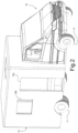
- Fig.1 schematically indicates a chassis 1 of a vehicle that can be equipped with a containing structure, hereinafter for brevity also "cell", which can be produced with the system of the present invention.
- the chassis 1 comprises a driver's cab 3, a supporting frame 5, front wheels 9 and rear wheels 11.
- chassis relates to a motorized vehicle
- chassis could be part of a towed vehicle, for example of a trailer.
- a cell or containing structure 13 is mounted on the frame 5 of the chassis 1, to obtain a vehicle 15, see Fig.2 .
- the cell 13 comprises a side access opening 13A, an optional rear access opening and a window 13B. It must be understood that the shape and the dimension of the containing structure 13 and of its openings can vary as a function of the uses for which the vehicle 15 is intended and of the shape and size of the chassis.
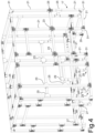
- the cell or containing structure 13 comprises in general a skeleton, consisting of a frame, an embodiment of which is illustrated in axonometric view in Fig.4 .
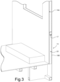
- the skeleton or frame indicated as a whole with 17 in Fig.4 , can be clad with inner and outer panels, indicated schematically with 19A and 19B in Fig.3 , where a partial sectional view of a fragment of the cell or containing structure 13 is shown.
- the reference number 20 indicates an insulation with heat and/or sound insulation capacities.
- the panels 19A, 19B can be made of polymer material, for example of polyester. In other embodiments, the panels 19A, 19B can be made of fiberglass or of aluminum.
- the skeleton or frame 17 of the containing structure 13 is formed with a system comprising segments of a tubular profile and joints or nodes connecting the segments of tubular profile.
- reference number 21 generically indicates the segments of tubular profile, which can be made of aluminum.
- the tubular profiles can be made of other materials, for example of a polymer, preferably a polymer charged with reinforcing fibers, such as carbon fibers or glass fibers. Examples of polymer-based materials that can be used for the tubular profiles and for the joints or nodes will be indicated below.
- the profile from which the segments 21 are obtained has a quadrangular, rectangular or square cross section. The choice of the cross section of the tubular profiles can be based on the type of intended use of the structure and the vehicle on which the structure is mounted.
- the segments of tubular profile 21 are advantageously rectilinear, so that each segment 21 can be obtained by cutting a single semi-finished product, i.e., a rectilinear profile.
- the system to build the skeleton or frame 17 of the containing structure 13 comprises five types of joints that are used to join, according to angles of 90°, segments of tubular profile 21 converging in a same node.
- the single joints are represented in the following figures, which will be described in detail below:
- the joints 23, 25, 27, 29, 31 can be made of plastic material, i.e., polymer-based material, optionally charged or reinforced.
- the polymers that can be used are polymers suitable for metal replacement.
- the choice of the material can be a function of the characteristics of mechanical strength required, of the weight of the structure and of the cost of the material. In some embodiments, it may be advantageous to use materials with higher costs and performance, hence characterized by improved parameters of mechanical strength, as they allow the total weight of the structure to be reduced.
- Suitable materials to be used to produce the joints include polyamides, for example a polyamide 6.6, charged with glass fibers, with percentages by weight of glass fiber for example of between 20% and 80%, preferably between 40% and 70%, even more preferably between 50% and 65%.
- Materials of this type based on polyamide 6.6 with 60% by weight of glass fiber are available from Lanxess GmbH with the trade name of Durethan ® BKV 60 EF DUS097 000000 and Durethan ® BKV60XF 900116.
- a polyamide 6, charged or not charged with fibers can be used.
- An example of a polymer based on uncharged polyamide 6 is available from Lanxess Deutschland GmbH with the trade name Durethan ® B 30 S000000.
- a blend of different polymers, with or without a charge of reinforcing fibers can be used.
- PET polyethylene terephthalate
- PBT polybutylene terephthalate
- reinforcing fibers for example glass fibers, for example present in a percentage of between 20% and 70% by weight, preferably between around 30% and around 60%, more preferably between around 40% and 50% by weight, can be used.
- a material of this type is available from Lanxess Deutschland GmbH, with the trade name of Pocan ® T 7391 0000000.
- polyphenylene sulfide for example one of the products marketed with the trade name Fortran ® PPS by Celanese Corporation, USA, can be used.
- tubular profiles joined by the joints are made of light metal, for example of aluminum, in other embodiments at least some of the polymers indicated above can be used to produce the tubular profiles.
- structures with high mechanical strength which offer the same performance with weights lower than structures that use metal profiles, can be produced using reinforced polymers with high mechanical properties.
- the configuration of the joints is appropriately chosen so that all the joints can be produced with a smaller number of molds with respect to the number of joints, for example by using removable inserts.
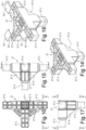
- the first joint 23, or X-shaped angular joint comprises a central core 23.1 from which four coplanar arms 23.2 angularly spaced at 90° with respect to one another, extend. Similarly to the other equivalent arms of the joints described below, the arms 23.2 form securing members of segments 21 of tubular profile converging at the joint 23.
- the four arms 23.2 are configured to be inserted into ends of four segments of tubular profile 21.
- the cross section of the arms 23.2 corresponds approximately to the cross section of the tubular profile, but with a smaller size, to allow an adhesive material to be inserted between the lateral surfaces of each arm 23.2 and the inner surface of the segment of tubular profile 21 and for the application of additional components, in the shape of covers 33 (see Fig.8 ), described in greater detail below.
- the tubular profiles 21 have a quadrangular section, for example measuring 40x60 mm. In other embodiments tubular profiles with a square section, for example measuring 60x60 mm, can be used.
- the thickness of the wall of the tubular profiles can for example be between around 1.5 mm and around 5 mm, preferably between around 2 mm and around 4 mm, for example between around 2.5 mm and 3.5 mm.
- the arms 23.2 of the joint have a complementary cross section, slightly smaller with respect to the cross section of the tubular profiles used.
- the difference in size between the two cross sections of the arms 23.2 and of the tubular profiles 21 that must be coupled with one another allows a layer of glue to be applied between them, in the manner described below.
- both the central core 23.1 and the arms 23.2 have on the inside a lattice structure 23.3 consisting of walls intersecting one another at 90°.
- the lattice structure 23.3 stiffens the joint 23, maintaining a light structure and reducing the amount of material required to produce it.
- a whole face of the joint 23 is advantageously open, as shown in Figs. 5, 6 and 8 .
- each arm 23.2 has a continuous closing surface on three sides and on the front end, and an open lower surface.
- each cover 33 is provided, which complete the continuous outer surface of each arm, as can be understood from Fig.8 .
- Each cover 33 can be applied with interlock on the respective arm, for example by means of tabs 33.1 that interlock in the inner lattice structure of the arm 23.2.
- the thickness of each cover 33 is advantageously chosen so that once coupled to the respective arm 23.2, the cross section of the arm becomes substantially the same as the inner section of the tubular profile, minus the thickness occupied by the glue with which the arm 23.2 of the joint 23 is made to adhere to the inner surface of the segment of tubular profile 21 into which said arm is inserted.
- the structure of the remaining joints 25, 27, 29, 31 is conceptually similar to that of the joint 23.
- the T-shaped joint 25, shown in Figs.9 to 13 has a central core 25.1 from which three T-shaped arms 25.2 extend.
- the inside of the central core 25.1 and of the arms 25. 2 has a lattice lightening and stiffening structure 25.3.
- Fig.13 shows three covers 33 adapted to be coupled to the arms 25.2 to complete the continuous outer surface of said arms.
- the joint 27 shown in Figs. 14 to 18 has, similarly to the joints 23 and 25, a central core 27.1 and arms 27.2 that extend from the central core 27.1.
- the reference number 27.3 indicates a lattice structure that fills the inner volume of the core 27.1 and of the arms 27.2 for the purposes described above in relation to the inner lattice structure of the joints 23 and 25.
- the number 27.4 indicates reinforcing gussets that join the arms 27.2 to the central core 27.1.
- Three arms 27.2 are arranged coplanar in the shape of a T, similarly to the three arms of the joint 25.
- the fourth arm is placed orthogonally to the plane on which the three T-shaped arms lie.
- Covers 33 can also be applied on the arms 27.2 of the joint 27, as described above.
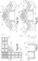
- the joint 29 has an L-shape with a core 29.1 from which two arms 29.2 extend oriented at 90° with respect to one another.
- the inside of the core 29.1 and of the arms 29.2 has a lattice structure 29.3 of diaphragms orthogonal to one another with the function of lightening and stiffening the joint, as described above.
- Fig.22 shows an axonometric bottom view of the joint 29 with covers 33 applicable on the faces of the arms 29.2 open toward the inside, to form, as described above for the other joints illustrated, a continuous outer surface of the arms 29.2.
- the joint 31 shown in Figs. 23 to 27 has a central core 31.1 with three arms 31.2 that extend according to three orthogonal axes from the core 31.1.
- the inside of the arms 31.2 and of the central core 31.1 is filled with a lattice structure 31.3 similar to the lattice structure described with reference to the previously described joints and with similar filling and stiffening functions.
- the number 31.4 indicates reinforcing gussets between the core 31.1 and the arms 31.2.
- Two coplanar arms 31.2 of the joint 31 are open on one side, as is visible in particular in Figs.23 , 27 .
- Covers 33 ( Fig.27 ) can be applied on the open faces of the arms to form a closed lateral surface with continuous contact with the inner surfaces of the segments of tubular profile 21 inserted on the arms 31.2.
- one of the arms can be made by molding with continuous and closed lateral surfaces (see arm 31.2 facing downward in Fig. 27 ).
- Fig.28 schematically shows the use of a joint 31 for mutually fastening three segments of tubular profile 21 converging in a node of the skeleton or frame 17.
- Fastening is advantageously obtained by gluing between the outer surfaces of the arms 31.2 (i.e., of the equivalent arms 23.2, 25.2 27.2, 29.2 for the joints 23, 25, 27, 29) and the inner surfaces of the segments 21 of tubular profile.
- the openings left open on one side of each arm, required by the technique of producing the joint by molding, are closed by means of the covers 33.
- Fig.28 two covers 33 are applied on the corresponding open faces of two arms 31.2.
- the reference number 35 indicates a layer of glue that is interposed between the continuous lateral surfaces of the arms 31.2 and the inner surfaces of the segments 21 of tubular profile.
- the glue can advantageously be a two-component adhesive.
- the glue can be applied by impregnating a strip of textile material with this glue and then applying it on the lateral surfaces of the arms 31.1 before their insertion into the ends of the segments 21 of tubular profile.
- the glue 35 is shown as if it were composed of a hollow prismatic body, but in actual fact it can be formed of turns of tape impregnated with glue wound around the respective arm of the joint.
- the system of joints and segments of profile described can be used to produce frames of containing structures destined for a wide variety of uses. For example and in particular, but not exclusively, with the system described it is possible to produce cells for ambulances, but also for other types of vehicles, such as mobile workshops, mobile offices or the like.
Landscapes
- Engineering & Computer Science (AREA)
- Chemical & Material Sciences (AREA)
- Combustion & Propulsion (AREA)
- Transportation (AREA)
- Mechanical Engineering (AREA)
- Body Structure For Vehicles (AREA)
- Automobile Manufacture Line, Endless Track Vehicle, Trailer (AREA)
Claims (14)
- System zum Zusammenbau eines Rahmens (17) für eine Aufnahmestruktur, die ausgebildet ist, um auf einem Fahrzeugchassis montiert zu werden; wobei das System umfasst:- eine Mehrzahl von Gelenken (23, 25, 27, 29, 31), die jeweils einen zentralen Kern (23.1; 25.1, 27.1, 29.1, 31.1) und eine Mehrzahl von Armen (23.2, 25.2, 27.2, 29.2, 31.2) aufweisen, die sich von dem zentralen Kern erstrecken und Befestigungselemente für eine jeweilige Mehrzahl von Segmenten von rohrförmigem Profil (21) bilden;- eine Mehrzahl von Segmenten von rohrförmigem Profil (21);wobei die Arme (23.2, 25.2, 27.2, 29.2, 31.2) und die Segmente von rohrförmigem Profil (21) einen viereckigen Querschnitt aufweisen;dadurch gekennzeichnet, dass die Gelenke (23, 25, 27, 29, 31) aus einem geformten Polymermaterial bestehen; die Gelenke ein Innenvolumen aufweisen, das durch eine gitterartige Erleichterungs- und Versteifungsstruktur (23.3, 25.3, 27.3, 29.3, 31. 3) gefüllt ist; für jedes Gelenk (23, 25, 27, 29, 31) sind Abdeckungen (33) für die offenen Seiten der Arme bereitgestellt, die ausgebildet sind, um mit den übrigen Seiten des jeweiligen Arms (23.2, 25.2, 27.2, 29.2, 31.2) eine durchgehende Außenfläche zu bilden.
- System gemäß Anspruch 1, wobei die Gelenke (23, 25, 27, 29, 31) aus einem geformten, mit Verstärkungsfasern versehenen Polymermaterial hergestellt sind.
- System gemäß Anspruch 1 oder 2, umfassend einen oder mehrere der Folgenden:- L-förmige Gelenke (29) mit zwei Schenkeln, die in einem Winkel von 90° zueinander ausgerichtet sind;- X-förmige Gelenke (23) mit vier koplanaren Armen, die um 90° zueinander ausgerichtet sind;- T-förmige Gelenke (25) mit drei koplanaren Schenkeln;- Gelenke (31) mit drei Armen, die nach drei kartesischen Achsen angeordnet sind;- Vierfachgelenke (27) mit drei koplanar angeordneten Armen in Form eines T und einem vierten Arm, der sich orthogonal zu der Ebene erstreckt, in der die drei koplanaren Arme liegen.
- System gemäß Anspruch 1 oder 2 oder 3, wobei mindestens einige der Gelenke (23, 25, 27, 29, 31) Verstärkungskeile (27.4, 31.4) zwischen dem Kern und mindestens einem der vom Kern ausgehenden Arme umfassen.
- System gemäß einem oder mehreren der vorangegangenen Ansprüche, wobei die Segmente von rohrförmigem Profil (21) aus einem Material hergestellt sind, das ausgewählt ist aus der Gruppe umfassend: ein Metall, insbesondere Aluminium, ein Polymer oder eine Polymermischung, ein Polymer oder eine Polymermischung, die mit Fasern, insbesondere Glasfasern, verstärkt ist.
- Rahmen (17) einer Aufnahmestruktur mit einer dreidimensionalen Konfiguration, ausgebildet, um an einem Fahrzeugfahrgestell montiert zu werden, wobei der Rahmen eine Mehrzahl von Segmenten von rohrförmigem Profil (21) umfasst, die miteinander verbunden sind, um die dreidimensionale Konfiguration mittels einer Mehrzahl von Gelenken (23, 25, 27, 29, 31) eines Systems gemäß einem oder mehreren der vorangehenden Ansprüche zu bilden; wobei jeder Knoten des Rahmens (17) durch eine der Gelenke (23, 25, 27, 29, 31) definiert ist; und wobei alle Segmente von rohrförmigem Profil (21), die in jedem Knoten zusammenlaufen, miteinander durch das jeweilige Gelenk (23, 25, 27, 29, 31), das den Knoten definiert, verbunden sind.
- Aufnahmestruktur für Fahrzeuge, umfassend einen Rahmen gemäß Anspruch 6.
- Aufnahmestruktur gemäß Anspruch 7, wobei der Rahmen außen und/oder innen mit Verkleidungsplatten (19A, 19B) verkleidet ist.
- Aufnahmestruktur gemäß Anspruch 8, umfassend eine Isolierung (20) zwischen einer Innenverkleidung (19A) und einer Außenverkleidung (19B) des Rahmens.
- Fahrzeug (15), umfassend ein Fahrgestell (1) und eine Aufnahmestruktur gemäß Anspruch 7, 8 oder 9.
- Verfahren zur Herstellung einer Aufnahmestruktur, die zum Einbau in ein Fahrzeug (15) ausgebildet ist, umfassend den Schritt des Verbindens von Segmenten von rohrförmigem Profil (21) miteinander mittels Verbindungsgelenken (23, 25, 27, 29, 31) eines Systems gemäß einem oder mehreren der Ansprüche 1 bis 5, wobei ein dreidimensionaler Rahmen (17) gebildet wird, der das Innere der Aufnahmestruktur begrenzt, wobei jeder Knoten des dreidimensionalen Rahmens durch ein jeweiliges Gelenk (23, 25, 27, 29, 31) definiert ist, das die Segmente von rohrförmigem Profil miteinander verbindet, die in dem jeweiligen Knoten zusammenlaufen.
- Verfahren gemäß Anspruch 11, wobei die Segmente von rohrförmigem Profil (21) mit den Armen der Gelenke (23, 25, 27, 29, 31) durch Kleben verbunden werden.
- Verfahren gemäß Anspruch 11 oder 12, wobei die Gelenke (23, 25, 27, 29, 31) aus einem Polymermaterial hergestellt sind.
- Verfahren gemäß einem oder mehreren der Ansprüche 11 bis 13, umfassend den Schritt des Anbringens von äußeren Verkleidungsplatten und vorzugsweise inneren Verkleidungsplatten des dreidimensionalen Rahmens und vorzugsweise umfassend einen weiteren Schritt des Einfügens einer Isolierung zwischen die äußeren und inneren Verkleidungsplatten, wobei die Isolierung Wärme- und/oder Schalldämmung bereitstellt.
Applications Claiming Priority (2)
| Application Number | Priority Date | Filing Date | Title |
|---|---|---|---|
| IT102018000021457A IT201800021457A1 (it) | 2018-12-31 | 2018-12-31 | Sistema per la realizzazione di una struttura contenitiva per veicoli cabinati o simili, metodo e veicolo ottenuto con detta struttura |
| PCT/IB2019/061280 WO2020141405A1 (en) | 2018-12-31 | 2019-12-23 | System for producing a containing structure for vehicles with cabs or the like, method and vehicle obtained with said structure |
Publications (3)
| Publication Number | Publication Date |
|---|---|
| EP3906183A1 EP3906183A1 (de) | 2021-11-10 |
| EP3906183B1 true EP3906183B1 (de) | 2024-02-07 |
| EP3906183C0 EP3906183C0 (de) | 2024-02-07 |
Family
ID=66166324
Family Applications (1)
| Application Number | Title | Priority Date | Filing Date |
|---|---|---|---|
| EP19838974.4A Active EP3906183B1 (de) | 2018-12-31 | 2019-12-23 | System zur herstellung einer aufnahmestruktur für fahrzeuge mit kabinen oder dergleichen, verfahren und fahrzeug mit dieser struktur |
Country Status (5)
| Country | Link |
|---|---|
| US (1) | US11772713B2 (de) |
| EP (1) | EP3906183B1 (de) |
| BR (1) | BR112021012605A2 (de) |
| IT (1) | IT201800021457A1 (de) |
| WO (1) | WO2020141405A1 (de) |
Families Citing this family (2)
| Publication number | Priority date | Publication date | Assignee | Title |
|---|---|---|---|---|
| EP4056943B1 (de) | 2021-03-12 | 2025-05-21 | ACS Armoured Car Systems GmbH | Modular aufbaubares fahrzeuggestell |
| KR20250041894A (ko) * | 2023-09-19 | 2025-03-26 | 현대자동차주식회사 | 차량의 차체 및 차체 연결조인트 |
Family Cites Families (12)
| Publication number | Priority date | Publication date | Assignee | Title |
|---|---|---|---|---|
| US5421666A (en) * | 1993-09-24 | 1995-06-06 | Spears; Donald L. | Pipe connector for framework fabrication |
| US6402414B1 (en) * | 2000-03-07 | 2002-06-11 | General Motors Corporation | Efficient tubular body joint |
| DE10327011A1 (de) * | 2003-06-12 | 2005-01-13 | Willy Voit Gmbh & Co. Stanz-Metallwerk | Verbindungselement für ebene oder räumliche Gitterstrukturen und Verfahren zum Herstellen eines derartigen Verbindungselements |
| CA2581059C (en) * | 2007-03-06 | 2014-12-30 | Ilir Beshiri | Tarp connector system and method of using same |
| DE102007018183A1 (de) * | 2007-04-18 | 2008-05-21 | Daimler Ag | Rahmenkonstruktion insbesondere für einen Omnibus |
| JP5013133B2 (ja) * | 2009-03-31 | 2012-08-29 | マツダ株式会社 | 自動車車体におけるチューブ状フレームの連結構造の組立方法 |
| DE102011117259A1 (de) * | 2011-10-27 | 2013-05-02 | C E S Control Enclosure Systems Gmbh | Eckverstärkungseinsatz |
| CA2801925A1 (en) * | 2012-01-05 | 2013-07-05 | Basf Se | Frame for a recreational vehicle |
| US10960929B2 (en) * | 2014-07-02 | 2021-03-30 | Divergent Technologies, Inc. | Systems and methods for vehicle subassembly and fabrication |
| JP6820843B2 (ja) * | 2014-07-02 | 2021-01-27 | ダイバージェント テクノロジーズ, インコーポレイテッドDivergent Technologies, Inc. | 継手部材を製造するためのシステム及び方法 |
| CN106080805B (zh) * | 2016-08-17 | 2019-09-10 | 广西南南铝加工有限公司 | 一种全铝车厢 |
| US9884540B1 (en) * | 2016-12-06 | 2018-02-06 | Walter Peter DeMonte | Rolling tarp enclosure system |
-
2018
- 2018-12-31 IT IT102018000021457A patent/IT201800021457A1/it unknown
-
2019
- 2019-12-23 BR BR112021012605-8A patent/BR112021012605A2/pt not_active Application Discontinuation
- 2019-12-23 US US17/419,483 patent/US11772713B2/en active Active
- 2019-12-23 EP EP19838974.4A patent/EP3906183B1/de active Active
- 2019-12-23 WO PCT/IB2019/061280 patent/WO2020141405A1/en not_active Ceased
Also Published As
| Publication number | Publication date |
|---|---|
| WO2020141405A1 (en) | 2020-07-09 |
| IT201800021457A1 (it) | 2020-07-01 |
| US11772713B2 (en) | 2023-10-03 |
| EP3906183A1 (de) | 2021-11-10 |
| EP3906183C0 (de) | 2024-02-07 |
| US20220073153A1 (en) | 2022-03-10 |
| BR112021012605A2 (pt) | 2021-09-08 |
Similar Documents
| Publication | Publication Date | Title |
|---|---|---|
| US9096271B2 (en) | Axle support of a vehicle, said support consisting of fiber-reinforced plastic material | |
| JP3428545B2 (ja) | 車体補強構造 | |
| US6349988B1 (en) | Vehicle with large planar composite panels | |
| US5403062A (en) | Panel joint for adhesively bonded wall panels | |
| US4978163A (en) | Cab structure for a heavy motor vehicle | |
| EP3906183B1 (de) | System zur herstellung einer aufnahmestruktur für fahrzeuge mit kabinen oder dergleichen, verfahren und fahrzeug mit dieser struktur | |
| US11772712B2 (en) | Composite floor with integrated conduit | |
| CN209781379U (zh) | 用于接合节点和管结构的装置 | |
| US20040262950A1 (en) | Composite pickup box for automotive vehicle | |
| US20050081474A1 (en) | Bonded structural joints and method of assembling such joints | |
| DE102007035772A1 (de) | Wagenkasten für ein Schienenfahrzeug | |
| CA2936857A1 (en) | Lightweight structural joiner | |
| EP0441313B1 (de) | Drehgestellrahmen für Schienenfahrzeug | |
| RU2487022C2 (ru) | Способ изготовления транспортных средств и транспортное средство, полученное таким способом | |
| JP7048632B2 (ja) | キャビンモジュール及びそれを搭載した自動車 | |
| KR102464314B1 (ko) | 전기 자동차용 배터리 팩 하부 케이스의 제조방법 | |
| WO2004000633A1 (en) | Platform made of fiber reinforced plastic for bus | |
| JP3287580B2 (ja) | 壁モジュールおよびその製作方法 | |
| CN210063157U (zh) | 一种通过拉挤成型梁来加强碳纤维地板横梁的地板结构 | |
| CN118514761A (zh) | 一种包裹架结构、白车身总成及车辆 | |
| CN220147425U (zh) | 箱梁式车架本体、车架总成及车辆 | |
| WO2004000634A1 (en) | Body made of fiber reinforced plastic, mainly for bus | |
| CN207207719U (zh) | 汽车及其后窗框后边框组件 | |
| KR102768578B1 (ko) | 차체 연결 구조 | |
| EP3640124B1 (de) | Vorrichtung zur stabilisierung von honeycomb-platten eines kastenförmigen ladegeräts |
Legal Events
| Date | Code | Title | Description |
|---|---|---|---|
| STAA | Information on the status of an ep patent application or granted ep patent |
Free format text: STATUS: UNKNOWN |
|
| STAA | Information on the status of an ep patent application or granted ep patent |
Free format text: STATUS: THE INTERNATIONAL PUBLICATION HAS BEEN MADE |
|
| PUAI | Public reference made under article 153(3) epc to a published international application that has entered the european phase |
Free format text: ORIGINAL CODE: 0009012 |
|
| STAA | Information on the status of an ep patent application or granted ep patent |
Free format text: STATUS: REQUEST FOR EXAMINATION WAS MADE |
|
| 17P | Request for examination filed |
Effective date: 20210628 |
|
| AK | Designated contracting states |
Kind code of ref document: A1 Designated state(s): AL AT BE BG CH CY CZ DE DK EE ES FI FR GB GR HR HU IE IS IT LI LT LU LV MC MK MT NL NO PL PT RO RS SE SI SK SM TR |
|
| DAV | Request for validation of the european patent (deleted) | ||
| DAX | Request for extension of the european patent (deleted) | ||
| GRAP | Despatch of communication of intention to grant a patent |
Free format text: ORIGINAL CODE: EPIDOSNIGR1 |
|
| STAA | Information on the status of an ep patent application or granted ep patent |
Free format text: STATUS: GRANT OF PATENT IS INTENDED |
|
| INTG | Intention to grant announced |
Effective date: 20230712 |
|
| GRAS | Grant fee paid |
Free format text: ORIGINAL CODE: EPIDOSNIGR3 |
|
| GRAA | (expected) grant |
Free format text: ORIGINAL CODE: 0009210 |
|
| STAA | Information on the status of an ep patent application or granted ep patent |
Free format text: STATUS: THE PATENT HAS BEEN GRANTED |
|
| AK | Designated contracting states |
Kind code of ref document: B1 Designated state(s): AL AT BE BG CH CY CZ DE DK EE ES FI FR GB GR HR HU IE IS IT LI LT LU LV MC MK MT NL NO PL PT RO RS SE SI SK SM TR |
|
| REG | Reference to a national code |
Ref country code: GB Ref legal event code: FG4D |
|
| REG | Reference to a national code |
Ref country code: CH Ref legal event code: EP |
|
| REG | Reference to a national code |
Ref country code: IE Ref legal event code: FG4D |
|
| REG | Reference to a national code |
Ref country code: DE Ref legal event code: R096 Ref document number: 602019046278 Country of ref document: DE |
|
| U01 | Request for unitary effect filed |
Effective date: 20240221 |
|
| U07 | Unitary effect registered |
Designated state(s): AT BE BG DE DK EE FI FR IT LT LU LV MT NL PT SE SI Effective date: 20240229 |
|
| REG | Reference to a national code |
Ref country code: LT Ref legal event code: MG9D |
|
| PG25 | Lapsed in a contracting state [announced via postgrant information from national office to epo] |
Ref country code: IS Free format text: LAPSE BECAUSE OF FAILURE TO SUBMIT A TRANSLATION OF THE DESCRIPTION OR TO PAY THE FEE WITHIN THE PRESCRIBED TIME-LIMIT Effective date: 20240607 |
|
| PG25 | Lapsed in a contracting state [announced via postgrant information from national office to epo] |
Ref country code: GR Free format text: LAPSE BECAUSE OF FAILURE TO SUBMIT A TRANSLATION OF THE DESCRIPTION OR TO PAY THE FEE WITHIN THE PRESCRIBED TIME-LIMIT Effective date: 20240508 |
|
| PG25 | Lapsed in a contracting state [announced via postgrant information from national office to epo] |
Ref country code: HR Free format text: LAPSE BECAUSE OF FAILURE TO SUBMIT A TRANSLATION OF THE DESCRIPTION OR TO PAY THE FEE WITHIN THE PRESCRIBED TIME-LIMIT Effective date: 20240207 Ref country code: RS Free format text: LAPSE BECAUSE OF FAILURE TO SUBMIT A TRANSLATION OF THE DESCRIPTION OR TO PAY THE FEE WITHIN THE PRESCRIBED TIME-LIMIT Effective date: 20240507 |
|
| PG25 | Lapsed in a contracting state [announced via postgrant information from national office to epo] |
Ref country code: ES Free format text: LAPSE BECAUSE OF FAILURE TO SUBMIT A TRANSLATION OF THE DESCRIPTION OR TO PAY THE FEE WITHIN THE PRESCRIBED TIME-LIMIT Effective date: 20240207 |
|
| PG25 | Lapsed in a contracting state [announced via postgrant information from national office to epo] |
Ref country code: RS Free format text: LAPSE BECAUSE OF FAILURE TO SUBMIT A TRANSLATION OF THE DESCRIPTION OR TO PAY THE FEE WITHIN THE PRESCRIBED TIME-LIMIT Effective date: 20240507 Ref country code: NO Free format text: LAPSE BECAUSE OF FAILURE TO SUBMIT A TRANSLATION OF THE DESCRIPTION OR TO PAY THE FEE WITHIN THE PRESCRIBED TIME-LIMIT Effective date: 20240507 Ref country code: IS Free format text: LAPSE BECAUSE OF FAILURE TO SUBMIT A TRANSLATION OF THE DESCRIPTION OR TO PAY THE FEE WITHIN THE PRESCRIBED TIME-LIMIT Effective date: 20240607 Ref country code: HR Free format text: LAPSE BECAUSE OF FAILURE TO SUBMIT A TRANSLATION OF THE DESCRIPTION OR TO PAY THE FEE WITHIN THE PRESCRIBED TIME-LIMIT Effective date: 20240207 Ref country code: GR Free format text: LAPSE BECAUSE OF FAILURE TO SUBMIT A TRANSLATION OF THE DESCRIPTION OR TO PAY THE FEE WITHIN THE PRESCRIBED TIME-LIMIT Effective date: 20240508 Ref country code: ES Free format text: LAPSE BECAUSE OF FAILURE TO SUBMIT A TRANSLATION OF THE DESCRIPTION OR TO PAY THE FEE WITHIN THE PRESCRIBED TIME-LIMIT Effective date: 20240207 |
|
| PG25 | Lapsed in a contracting state [announced via postgrant information from national office to epo] |
Ref country code: PL Free format text: LAPSE BECAUSE OF FAILURE TO SUBMIT A TRANSLATION OF THE DESCRIPTION OR TO PAY THE FEE WITHIN THE PRESCRIBED TIME-LIMIT Effective date: 20240207 |
|
| PG25 | Lapsed in a contracting state [announced via postgrant information from national office to epo] |
Ref country code: PL Free format text: LAPSE BECAUSE OF FAILURE TO SUBMIT A TRANSLATION OF THE DESCRIPTION OR TO PAY THE FEE WITHIN THE PRESCRIBED TIME-LIMIT Effective date: 20240207 |
|
| PG25 | Lapsed in a contracting state [announced via postgrant information from national office to epo] |
Ref country code: SM Free format text: LAPSE BECAUSE OF FAILURE TO SUBMIT A TRANSLATION OF THE DESCRIPTION OR TO PAY THE FEE WITHIN THE PRESCRIBED TIME-LIMIT Effective date: 20240207 |
|
| PG25 | Lapsed in a contracting state [announced via postgrant information from national office to epo] |
Ref country code: CZ Free format text: LAPSE BECAUSE OF FAILURE TO SUBMIT A TRANSLATION OF THE DESCRIPTION OR TO PAY THE FEE WITHIN THE PRESCRIBED TIME-LIMIT Effective date: 20240207 |
|
| PG25 | Lapsed in a contracting state [announced via postgrant information from national office to epo] |
Ref country code: SK Free format text: LAPSE BECAUSE OF FAILURE TO SUBMIT A TRANSLATION OF THE DESCRIPTION OR TO PAY THE FEE WITHIN THE PRESCRIBED TIME-LIMIT Effective date: 20240207 |
|
| PG25 | Lapsed in a contracting state [announced via postgrant information from national office to epo] |
Ref country code: SM Free format text: LAPSE BECAUSE OF FAILURE TO SUBMIT A TRANSLATION OF THE DESCRIPTION OR TO PAY THE FEE WITHIN THE PRESCRIBED TIME-LIMIT Effective date: 20240207 Ref country code: SK Free format text: LAPSE BECAUSE OF FAILURE TO SUBMIT A TRANSLATION OF THE DESCRIPTION OR TO PAY THE FEE WITHIN THE PRESCRIBED TIME-LIMIT Effective date: 20240207 Ref country code: RO Free format text: LAPSE BECAUSE OF FAILURE TO SUBMIT A TRANSLATION OF THE DESCRIPTION OR TO PAY THE FEE WITHIN THE PRESCRIBED TIME-LIMIT Effective date: 20240207 Ref country code: CZ Free format text: LAPSE BECAUSE OF FAILURE TO SUBMIT A TRANSLATION OF THE DESCRIPTION OR TO PAY THE FEE WITHIN THE PRESCRIBED TIME-LIMIT Effective date: 20240207 |
|
| REG | Reference to a national code |
Ref country code: DE Ref legal event code: R097 Ref document number: 602019046278 Country of ref document: DE |
|
| PLBE | No opposition filed within time limit |
Free format text: ORIGINAL CODE: 0009261 |
|
| STAA | Information on the status of an ep patent application or granted ep patent |
Free format text: STATUS: NO OPPOSITION FILED WITHIN TIME LIMIT |
|
| 26N | No opposition filed |
Effective date: 20241108 |
|
| PG25 | Lapsed in a contracting state [announced via postgrant information from national office to epo] |
Ref country code: MC Free format text: LAPSE BECAUSE OF FAILURE TO SUBMIT A TRANSLATION OF THE DESCRIPTION OR TO PAY THE FEE WITHIN THE PRESCRIBED TIME-LIMIT Effective date: 20240207 |
|
| REG | Reference to a national code |
Ref country code: CH Ref legal event code: PL |
|
| U90 | Renewal fees not paid: noting of loss of rights |
Free format text: RENEWAL FEE NOT PAID FOR YEAR 06 Effective date: 20250716 |
|
| GBPC | Gb: european patent ceased through non-payment of renewal fee |
Effective date: 20241223 |
|
| PG25 | Lapsed in a contracting state [announced via postgrant information from national office to epo] |
Ref country code: GB Free format text: LAPSE BECAUSE OF NON-PAYMENT OF DUE FEES Effective date: 20241223 |
|
| PG25 | Lapsed in a contracting state [announced via postgrant information from national office to epo] |
Ref country code: CH Free format text: LAPSE BECAUSE OF NON-PAYMENT OF DUE FEES Effective date: 20241231 |
|
| PG25 | Lapsed in a contracting state [announced via postgrant information from national office to epo] |
Ref country code: IE Free format text: LAPSE BECAUSE OF NON-PAYMENT OF DUE FEES Effective date: 20241223 |
|
| U93 | Unitary patent lapsed |
Free format text: RENEWAL FEE NOT PAID Effective date: 20241231 |