EP3904705B1 - Halter für einsatz und anordnung mit dem halter und dem einsatz - Google Patents
Halter für einsatz und anordnung mit dem halter und dem einsatz Download PDFInfo
- Publication number
- EP3904705B1 EP3904705B1 EP20315233.5A EP20315233A EP3904705B1 EP 3904705 B1 EP3904705 B1 EP 3904705B1 EP 20315233 A EP20315233 A EP 20315233A EP 3904705 B1 EP3904705 B1 EP 3904705B1
- Authority
- EP
- European Patent Office
- Prior art keywords
- insert
- housing
- holder
- assembly
- plane
- Prior art date
- Legal status (The legal status is an assumption and is not a legal conclusion. Google has not performed a legal analysis and makes no representation as to the accuracy of the status listed.)
- Active
Links
Images

Classifications
-
- F—MECHANICAL ENGINEERING; LIGHTING; HEATING; WEAPONS; BLASTING
- F16—ENGINEERING ELEMENTS AND UNITS; GENERAL MEASURES FOR PRODUCING AND MAINTAINING EFFECTIVE FUNCTIONING OF MACHINES OR INSTALLATIONS; THERMAL INSULATION IN GENERAL
- F16B—DEVICES FOR FASTENING OR SECURING CONSTRUCTIONAL ELEMENTS OR MACHINE PARTS TOGETHER, e.g. NAILS, BOLTS, CIRCLIPS, CLAMPS, CLIPS OR WEDGES; JOINTS OR JOINTING
- F16B5/00—Joining sheets or plates, e.g. panels, to one another or to strips or bars parallel to them
- F16B5/02—Joining sheets or plates, e.g. panels, to one another or to strips or bars parallel to them by means of fastening members using screw-thread
- F16B5/0258—Joining sheets or plates, e.g. panels, to one another or to strips or bars parallel to them by means of fastening members using screw-thread using resiliently deformable sleeves, grommets or inserts
-
- F—MECHANICAL ENGINEERING; LIGHTING; HEATING; WEAPONS; BLASTING
- F16—ENGINEERING ELEMENTS AND UNITS; GENERAL MEASURES FOR PRODUCING AND MAINTAINING EFFECTIVE FUNCTIONING OF MACHINES OR INSTALLATIONS; THERMAL INSULATION IN GENERAL
- F16B—DEVICES FOR FASTENING OR SECURING CONSTRUCTIONAL ELEMENTS OR MACHINE PARTS TOGETHER, e.g. NAILS, BOLTS, CIRCLIPS, CLAMPS, CLIPS OR WEDGES; JOINTS OR JOINTING
- F16B19/00—Bolts without screw-thread; Pins, including deformable elements; Rivets
- F16B19/02—Bolts or sleeves for positioning of machine parts, e.g. notched taper pins, fitting pins, sleeves, eccentric positioning rings
-
- F—MECHANICAL ENGINEERING; LIGHTING; HEATING; WEAPONS; BLASTING
- F16—ENGINEERING ELEMENTS AND UNITS; GENERAL MEASURES FOR PRODUCING AND MAINTAINING EFFECTIVE FUNCTIONING OF MACHINES OR INSTALLATIONS; THERMAL INSULATION IN GENERAL
- F16B—DEVICES FOR FASTENING OR SECURING CONSTRUCTIONAL ELEMENTS OR MACHINE PARTS TOGETHER, e.g. NAILS, BOLTS, CIRCLIPS, CLAMPS, CLIPS OR WEDGES; JOINTS OR JOINTING
- F16B41/00—Measures against loss of bolts, nuts, or pins; Measures against unauthorised operation of bolts, nuts or pins
- F16B41/002—Measures against loss of bolts, nuts or pins
-
- F—MECHANICAL ENGINEERING; LIGHTING; HEATING; WEAPONS; BLASTING
- F16—ENGINEERING ELEMENTS AND UNITS; GENERAL MEASURES FOR PRODUCING AND MAINTAINING EFFECTIVE FUNCTIONING OF MACHINES OR INSTALLATIONS; THERMAL INSULATION IN GENERAL
- F16B—DEVICES FOR FASTENING OR SECURING CONSTRUCTIONAL ELEMENTS OR MACHINE PARTS TOGETHER, e.g. NAILS, BOLTS, CIRCLIPS, CLAMPS, CLIPS OR WEDGES; JOINTS OR JOINTING
- F16B2/00—Friction-grip releasable fastenings
- F16B2/20—Clips, i.e. with gripping action effected solely by the inherent resistance to deformation of the material of the fastening
- F16B2/22—Clips, i.e. with gripping action effected solely by the inherent resistance to deformation of the material of the fastening of resilient material, e.g. rubbery material
- F16B2/24—Clips, i.e. with gripping action effected solely by the inherent resistance to deformation of the material of the fastening of resilient material, e.g. rubbery material of metal
- F16B2/241—Clips, i.e. with gripping action effected solely by the inherent resistance to deformation of the material of the fastening of resilient material, e.g. rubbery material of metal of sheet metal
- F16B2/243—Clips, i.e. with gripping action effected solely by the inherent resistance to deformation of the material of the fastening of resilient material, e.g. rubbery material of metal of sheet metal internal, i.e. with spreading action
-
- F—MECHANICAL ENGINEERING; LIGHTING; HEATING; WEAPONS; BLASTING
- F16—ENGINEERING ELEMENTS AND UNITS; GENERAL MEASURES FOR PRODUCING AND MAINTAINING EFFECTIVE FUNCTIONING OF MACHINES OR INSTALLATIONS; THERMAL INSULATION IN GENERAL
- F16B—DEVICES FOR FASTENING OR SECURING CONSTRUCTIONAL ELEMENTS OR MACHINE PARTS TOGETHER, e.g. NAILS, BOLTS, CIRCLIPS, CLAMPS, CLIPS OR WEDGES; JOINTS OR JOINTING
- F16B39/00—Locking of screws, bolts or nuts
- F16B39/02—Locking of screws, bolts or nuts in which the locking takes place after screwing down
- F16B39/10—Locking of screws, bolts or nuts in which the locking takes place after screwing down by a plate, spring, wire or ring immovable with regard to the bolt or object and mainly perpendicular to the axis of the bolt
- F16B39/108—Locking of screws, bolts or nuts in which the locking takes place after screwing down by a plate, spring, wire or ring immovable with regard to the bolt or object and mainly perpendicular to the axis of the bolt with a locking washer under the nut or bolt head having at least one tongue or lug folded against the nut or bolt head, or against the object itself
-
- F—MECHANICAL ENGINEERING; LIGHTING; HEATING; WEAPONS; BLASTING
- F16—ENGINEERING ELEMENTS AND UNITS; GENERAL MEASURES FOR PRODUCING AND MAINTAINING EFFECTIVE FUNCTIONING OF MACHINES OR INSTALLATIONS; THERMAL INSULATION IN GENERAL
- F16B—DEVICES FOR FASTENING OR SECURING CONSTRUCTIONAL ELEMENTS OR MACHINE PARTS TOGETHER, e.g. NAILS, BOLTS, CIRCLIPS, CLAMPS, CLIPS OR WEDGES; JOINTS OR JOINTING
- F16B2200/00—Constructional details of connections not covered for in other groups of this subclass
- F16B2200/20—Connections with hook-like parts gripping behind a blind side of an element to be connected
Definitions
- the present disclosure relates to the field of mounting parts which are typically designed to be fastened against a support and used as accessories for holding an object such as cable channels, fixing clamps, plastic boxes or any other similar products. More specifically, the present disclosure relates to a holder for an insert and an assembly comprising such holder and insert.
- a fixing lug used as a mounting part for holding and fastening a base plate, a wiring duct or a cable tie.
- a fixing lug typically comprises a hole for receiving a screw to be screwed into a support.
- the fixing lugs or other similar connectors, on which the screw or a screw-nut system is supported are subjected to high mechanical stress. This phenomenon is all the more pronounced when the base plate or the connectors is made of a plastic material.
- mounting parts comprising a through-hole into which an insert, such as a metal strip or bushing, is placed around the inner face of the hole so that the screw or screw-nut system rests on the edge of the insert and not only on the plastic surface of the mounting part.
- the projection must have a certain elasticity for being firstly compressed by the edge of the insert until the recess of the latter comes in front of the projection for its engagement, thus releasing the projection from any compression force. Since the projection extends entirely outwards the inner wall of the through-hole, i.e. over the entire periphery of the projection, there is a risk that such a projection will break, thus rendering the mounting part unusable. Such a risk is increased by the fact that the fixing connector, including the projection, is made of a plastic material and that the insert is typically made of metallic material in order to have the requested strength for fastening purposes.
- Document DE102009011547A1 discloses a sliding element for sliding engagement into longitudinal groove, e.g. a groove of a mudguard of motor vehicle.
- this sliding element has typically a square shape and is provided with a through-hole in its center.
- the through-hole is designed for holding a sleeve due to projections protruding from the inner wall of the through-hole and engaging a recess made in sleeve when the latter is inserted into the through-hole.
- This element has the same drawbacks as those already mentioned in connection with the previously cited document.
- US 2013/0259595 A1 discloses a structure of an installation member for installation to a vehicle outer panel comprising a metallic retaining portion, a resin-made attachment, and a bolt.
- the present invention provides an assembly comprising an insert and a holder. This assembly is defined in claim 1.
- the second housing which is that in which the insert is lodged in its working or final position, is advantageously reachable by the insert in a direction which is different from that allowing the insertion of the insert into the opening of holder.
- the attachment of the insert with the holder is much more efficient than that of conventional solutions.
- the present disclosure may easily prevent any loosing of the insert once it is located in the second housing. Still advantageously, the present holder allows an easy and reliable assembly without the need for complex tools, or even without any mechanical assistance.
- the insert may, for example, be maintained locked in the holder despite a significant pulling force, without the need for over molding or stamping the insert.
- the opening (arranged in the holder) is a through-opening.
- the second housing preferably comprises a plurality of protrusions for preventing movement of the insert in directions perpendicular to the plane of the holder.
- the first housing is separated from the second housing by a divider.
- the second housing comprises two opposite sidewalls linked by a curved portion at one end of said second housing, and the first housing comprises at least a portion of the opposite sidewalls.
- the holder is devoid of any elastic part.
- the holder comprises a plastic material.
- the U-shape is elongated and open at one end so as to form two branches making up said elastic portion.
- each of the branches has a fork as a first locking means for engaging with one protrusion of the second housing of the holder.
- the fork is configured to be bent outwards so as to lock the insert in the second housing and prevent the insert from moving from the second housing to the first housing due to the divider acting as an abutment for the fork.
- the insert has a hole or a recess as a second locking means located at the opposite of the open end to engage with one of the protrusions of the second housing.
- the insert comprises a metallic material.
- the insert is configured to be maintained locked in the second housing against a force up to at least 12daN applied to the insert in any direction perpendicular to the plane or substantially perpendicular to this plane.
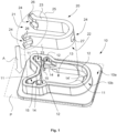
- Fig. 1 illustrates an example of a holder 10 according to an embodiment of the present disclosure.
- Fig. 1 shows on the one hand the holder 10 at the bottom of this figure, and on the other hand an insert 20 which is configured to be inserted into the holder 10.
- the holder 10 has a plane P which, in the present example, is parallel to the base of the holder 10.
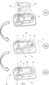
- Fig. 2 is a plan view of the holder 10 of Fig. 1 .
- the holder 10 has a first housing 11 and a second housing 12, both of them being configured for receiving the insert 20.
- the position of the insert 20 as located in the first housing 11 is depicted with a dashed line.
- the first housing 11 extends within the plane P of the holder.
- the position of the insert 20 as located in the second housing 12 is depicted with a dot-dash line.
- the second housing 12 also extends within the plane P of the holder.
- the first and second housings 11, 12 are integral with the holder 10, in particular with a main body of the holder 10.
- the main body of the holder 10 may be configured to be placed against a support (not shown).
- the main body of the holder 10 may comprise a base 10a configured to come into contact with such a support in order to increase the stability of the holder 10.
- the first and second housings 11, 12 comprise a sidewall structure 10b extending perpendicularly from the base 10a of the holder 10.
- the base 10a may be a planar structure and may comprise a webbed portion extending laterally around the periphery of the sidewall structure 10b.
- the sidewall structure 10b, especially the upper or free edge of the sidewall structure 10b, is preferably used to support a nut 42 of a screw-nut system 40 shown in Figs. 5-6 .
- the opposite edge of the structure is attached to the base 10a of the main body of the holder 10. Accordingly, the upper or free edge of the sidewall structure 10b is preferably parallel to the base 10a.
- the first and second housings 11, 12 may have an identical or similar footprint as shown in Fig. 2 .
- the first housing 11 is configured for a first position of the insert 20 within the holder 10
- the second housing 12 is configured for a second position of the insert 20 within the holder 10.
- the second housing 12 comprises two opposite sidewalls 12a, 12b linked by a curved portion 12c at one end of the second housing 12, and the first housing 11 comprises at least a portion of the opposite sidewalls 12a, 12b.
- the sidewalls 12a, 12b are parallel to each other and the curved portion 12c may have a circular shape and preferably has a semicircular shape.
- the lateral walls of the openings 11, 12, in particular the sidewalls 12a, 12b and the curved portion 12c, are perpendicular to the plane P. It will be understood that the sidewalls 12a, 12b and the curved portion 12c are part of the sidewall structure 10b shown in Figure 1 .
- the holder 10 further has an opening 13 for inserting, transversely or perpendicularly to the plane P or even substantially perpendicularly to this plane, the insert 20 into the first housing 11.
- the insertion of the insert 20 into the first housing 11 of the holder 10 is typically achieved in the direction of the arrow A of Fig. 1 .
- the second housing 12 is in communication with the first housing 11, so that it is possible to pass from one housing to another in a translational or sliding motion.
- the first and second housings 11, 12 are linked in a row.
- the second housing 12 extends within the plane P of the holder 10 and is configured to prevent the insert 20 from being moved out of the holder 10, in directions perpendicular to the plane P.
- the first and second housings 11, 12 are located at different locations within the same plane P, and the second housing 12 has means for preventing the insert 20 from being moved out of the holder 10 in directions perpendicular to the plane P.
- the second housing 12 which is configured for the final or working position of the insert 20, is offset relative to the opening 13 through which the insert 20 is inserted into the holder 10. Such an offset corresponds to the distance D (shown in Fig. 2 ) between the first housing 11 and the second housing 12.
- the first housing 11 is aligned with the insertion direction of the insert 20 through the opening 13, as depicted by the arrow A. Accordingly, the second housing 12 is advantageously offset from this insertion direction, thus allowing to provide the second housing 12 with efficient means for preventing the insert 20 from being removed out of the holder 10 in any direction perpendicular to the plane P or substantially perpendicular to this plane.
- the opening 13 is a through-opening as shown in Figs. 1-4 .
- the opening 13 through which the insert 20 is inserted into the holder 10 may be a blind opening or a partially blind opening, even if the second housing 12 is kept at least partially open in order to be crossed by a screw or a nut-screw system 40, shown in Figs. 5-6 , for fastening the holder 10 onto any kind of support.
- the distance D between the first and second housings 11, 12 is long enough, one may envisage a case where the opening 13, and thereby the first housing 11, is blind, whereas the second housing 12 remains through to pass e.g. a screw through the holder 10.
- the second housing 12 has a plurality of protrusions 14, 14' for blocking the insert 20 in both sides of the plane P.
- the protrusions 14 are located on the sidewalls 12a, 12b while the other protrusion 14' is located on the curved portion 12c of the second housing 12.
- the protrusions 14, 14' are located halfway up the sidewalls 12a, 12c and the curved portion 12c.
- the holder 10 allows the insert 20 to be inserted therein in a first direction, shown by the arrow A (in order to reach the first housing 11), and then to slide the insert 20 in a second direction, different from the first direction (in order to reach the second housing 12), it is possible to provide the second housing 12 with particularly robust protrusions 14, 14', as better shown in Fig. 1 .
- the protrusions 14, 14' may advantageously not be engaged during the positioning of the insert 20, namely during the time interval required for lodging the insert 20 from the outside of the holder 10 to the second housing 12 within the holder 10.
- the protrusions 14, 14' can benefit from a very robust architecture without affecting the insertion of the insert 20 into the holder 10 or interfering with the insert 20.
- the insert 20 can be secured in the holder 10 with a great efficiency against a tearing force acting in any direction perpendicular to the plane P or transversely to this plane.
- the second housing 12 instead of providing the second housing 12 with a plurality of protrusions, it may be possible to provide the second housing with recesses for blocking the insert in both sides of the plane P.
- the insert may be provided with projections that may each engage one recess.
- the first housing 11 is separated from the second housing 12 by a divider 15.
- the protrusions 14 and the divider 15 define the division between the first and second housings 11, 12.
- a divider 15 advantageously allows to lock the insert 20 in a direction parallel to the plane P given that it prevents the insert 20 from sliding back to the first housing 11 once it has reached the second housing 12.
- the divider 15 may comprise a protruding portion extending laterally into the centre of the holder 10 from both inner walls of the opening 13. The protruding portion defines the separation of the first and second housings 11 and 12.
- a divider 15 lies in the fact that the protrusions, especially the protrusions 14, can be integrally formed with the divider 15 on the one hand, and the inner wall of the opening 13 on the other hand. Consequently, the protrusion 14 becomes stronger than a projection extending entirely outwards from the inner wall of the opening 13, i.e. protruding over the entire periphery of the projection.
- Fig. 4 shows a kinematics sequence for assembling the insert 20 and the holder 10, shown in the previous Figures.
- Such an assembly is advantageously very easy to implement given that it requires only two steps between the first state S1 and the last state S3.
- the insert 20 is fully separated from the holder 10.
- the insert 20 is located above the holder 10 in front of the opening 13 of the holder.
- the goal of the first step is to put the insert 20 into the holder 10, especially into the first housing 11 of the holder 10, by inserting the insert 20 into the opening 13 so as to reach the second state S2.
- Such an insertion is preferably achieved without effort or stress, neither on the insert 20, nor on the holder 10.
- the second step aims to slide the insert 20 within the plane P of the holder 10, especially in the direction shown by arrow B, in order to put the insert 20 into the second housing 12 of the holder 10.
- the insert 20 may have to comprise an elastic portion 25 in order to allow it to move from the first housing 11 to the second housing 12.
- the insert 20 does not need to comprise such an elastic portion 25.
- the elastic portion of the insert can be regarded as being optional, depending on the embodiment of the holder 10.
- the plane P of the holder defines a plane of symmetry of the holder, as shown in Fig. 1 . Therefore, such a plane may be the median plane of the holder 10.
- the holder may be advantageously used to equal benefit on both sides, further simplifying its use.
- the holder 10 is devoid of any elastic component. Since the insert 20 is the main part of the assembly 30 designed to resist the tightening torque, namely to take up the forces when the assembly 30 is fastened on a support, this insert 20 is typically made of a strong material such as metal which is therefore specifically adapted for those purposes. On the other hand, the holder 10 may be made of plastic material. By not including any elastic component in the holder 10, such as elastic protrusions, the risk of breakage of one of the most sensitive parts of the holder is reduced.
- the holder 10 comprises a plastic material. Still preferably, the holder 10 is entirely made of plastic material, such as injected plastic material for example.
- a plastic holder can be easily adapted to other components such as plastic cable channels, fixing clamps, plastic boxes or other injected products.
- the shape of the holder, especially at least one of the first and second housings 11, 12, may be easily adapted for any kind of insert 20, such as round, oblong or rectangular inserts for example.
- the holder 10 is configured to maintain the insert 20 in a locked position in the second housing 12 in an efficient manner, without the need for over molding or stamping the insert. Furthermore, the holder 10 is configured to still allow the insertion of the insert 20 from one lateral side of the holder 10, namely a profile insertion in a direction perpendicular to the plane P of the holder 10. In addition, since the protrusions 14, 14' can be strong and sized appropriately, there is no need to have tight manufacturing tolerances between the insert 20 and the holder 10, especially between the insert 10 and at least one of the opening 13, the first housing 11 and second housing 12 of the holder 10. Accordingly, the holder of the present disclosure is not only efficient and reliable but also cost-effective.
- the present disclosure also relates to the assembly 30 comprising the insert 20 and the holder 10 according to any of the embodiments or variants disclosed therein, or according to any possible combination of such embodiments.
- the assembly 30 is characterized in that the insert 10 has a U-shape configured to fit with both the first and second housings 11, 12 and further has locking means 24 for locking the insert in the second housing 12. These locking means 24 are shown e.g. on Fig. 1 and will be detailed later in the present description.
- the insert 20 further has an elastic portion 25 which is adapted to be compressed when the insert 20 is moved between the first housing 11 and the second housing 12, as explained in connection with the kinematics sequence shown in Fig. 4 .
- the elastic portion 25 has a released state when the insert 20 is at least in the second housing 12 of the holder 10. This released state corresponds to the state of the insert 10 when no stress or force is applied thereon. Accordingly, the released state is that shown in Fig. 1 when the insert 20 is located outside of the holder 10.
- the elastic portion 25 of the insert 20 has also a released state in the first housing 11 of the holder 10.
- no stress is applied onto the insert 20 as long as the assembly 30 is not used, namely fastened to a support, except when passing the divider 15, if any.
- the U-shape of the insert 20 is elongated and open at one end 21 so as to form two branches 23 making up the elastic portion 25.
- the insert 20 has a U-shape with prongs, as locking means 24, extending outwardly at the open end 21.
- each of the branches 23 has a fork 26 as a first locking means 24 for engaging with one protrusion 14 of the second housing 12 of the holder 10.
- a locking means in the form of such a fork 26, instead of a hole allows to engage the two longitudinal ends of the protrusion 14 with the body of the holder 10, especially to the divider 15 and to the inner wall of the opening 13. Accordingly, the protrusion 14 becomes stronger and can resist higher stresses, in particular in the directions perpendicular to the plane P of the holder.
- the fork 26 is bent outwards, so as to lock the insert 20 in the second housing 12 and prevent the insert from moving back from the second housing 12 to the first housing 11 due to the divider 15 acting as an abutment for the fork 26.
- the fork 26 avoids the loss of the insert 20, once it is placed in its holder 10, and further locks the insert 20 in all directions.
- the insert has at least one hole 27 or a recess as a second locking means 24 located at an opposite end 22 of the open end 21.
- This hole 27 is designed to engage with one of the protrusions 14 of the second housing 12, especially with the protrusion 14' better shown in Fig. 2 .
- the hole 27 is designed to engage with the protrusion 14' within the plane P or within a plane parallel to the plane P, there is advantageously no stress applied to the insert 20 or the holder 10, during the engagement of these elements.
- the protrusion 14' can be designed to be quite large and therefore particularly strong, so as to resist significant forces applied to the insert 20, transversely to the plane P.
- the insert 20 comprises a metallic material.
- the insert 20 is entirely made of metallic material, such as aluminum, steel, stainless steel or any other metal or metal alloy. Nevertheless, the insert 20 may also be made from any other material.
- the insert 20 is designed to be maintained locked in the second housing 12 against a force up to at least 12daN applied onto the insert 20 in any direction perpendicularly to the plane P or substantially transversely to this plane.
- a significant value of stress can be reached, without over molding or stamping operations, thanks to the protrusions 14, 14' of the holder 10 which, according to the present disclosure, can be advantageously oversized relative to conventional solutions.
- This is mainly due to the fact that the protrusions 14, 14' of the holder 10 and the corresponding locking means 24 of the insert 20 are not engaged during the insertion of the insert 20 into the second housing 12, i.e. into its final position within the holder 10. This results to the specific architecture of the assembly 30, especially that of the holder 10.
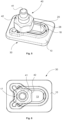
- Figs 5 and 6 respectively illustrate the assembly 30 as it appears when it is fastened by a screw-nut system 40, taken as example of a fixing means, according to an embodiment of the present disclosure.
- the system 40 comprises at least a screw 41 and a nut 42.
- the screw 41 is designed to go through the opening 13 in order to be fastened on a support not shown, below the holder 10.
- the nut 42 is typically designed to tight the assembly 30 against this support. To this end, the nut 42 rests against edges 18, 28 respectively of the holder 10 and the insert 20. Due to the strength of the insert 10, the majority of the force applied onto the assembly 30 by the nut 42 is supported by the insert 10 via its edges 18. Accordingly, an efficient tightening force can be provided by the screw-nut system for fastening the assembly 30 without damaging or even destroying the holder 10.
- Fig. 6 shows a plan view of Fig. 5 .
- one the holder 10 may further comprise at least one bulge 17 located on the periphery or around the opening 13.
- Such a bulge 17 may be a lump, a swelling, a bump or any similar projection.
- the bulge 17 is preferably located at one end of the opening 13 if the latter is not circular, and still preferably where the open end 21 of the insert is located when it is lodged in the holder 10.
- the bulge 17 acts as a stop for the screw 41, in order to ensure that the nut 42 is at least partly supported by the insert 20, especially in contact with at least a portion, preferably a sufficient portion, of the edge 18 of the insert 20 as shown in Fig. 6 . Due to the bulge 17, the holder 10 can ensure a limit position of the screw-nut system 40 and ensure that the system 40 is well positioned relative to the position of the insert 20, more specifically relative to the second housing 12.
- the assembly 30 of the present disclosure may be used as a mounting part or accessory, for example to fasten any product to a support, such as boxes, cable channels, fixing clamps, or other related products.
Landscapes
- Engineering & Computer Science (AREA)
- General Engineering & Computer Science (AREA)
- Mechanical Engineering (AREA)
- Clamps And Clips (AREA)
Claims (15)
- Eine Baugruppe (30) mit einem Einsatz (20) und einem Halter (10) für den Einsatz (20), wobeider Halter (10) umfasst:- ein erstes Gehäuse (11) zur Aufnahme des Einsatzes (20), wobei sich das erste Gehäuse (11) innerhalb einer Ebene (P) des Halters (10) erstreckt,- eine Öffnung (13) zum Einführen des Einsatzes (20) in das erste Gehäuse (11) in einer ersten Richtung, die im Wesentlichen senkrecht zu der Ebene (P) verläuft, und- ein zweites Gehäuse (12) zur Aufnahme des Einsatzes (20), wobei das zweite Gehäuse (12) mit dem ersten Gehäuse (11) in Verbindung steht und sich innerhalb der Ebene (P) des Halters (10) erstreckt; undder Einsatz (20) eine U-Form hat, die so konfiguriert ist, dass er sowohl zu dem ersten als auch zu dem zweiten Gehäuse (11, 12) passt, und ferner Verriegelungsmittel (24) zum Verriegeln des Einsatzes (20) im zweiten Gehäuse (12) umfasst; undwobeidas erste und das zweite Gehäuse so angeordnet sind, dass sie dem Einsatz (20) ermöglichen, in einer zweiten Richtung zu gleiten, die sich von der ersten Richtung unterscheidet und parallel zu der genannten Ebene verläuft, so dass er von dem ersten Gehäuse (11) zu dem zweiten Gehäuse (12) gelangt;das zweite Gehäuse (12) so konfiguriert ist, dass es eine Bewegung des Einsatzes (20) aus dem Halter (10) heraus in Richtungen senkrecht zu der Ebene (P) verhindert; undder Einsatz (20) ferner einen elastischen Abschnitt (25) umfasst, der so gestaltet ist, dass er zusammengedrückt wird, wenn der Einsatz (20) zwischen dem ersten Gehäuse (11) und dem zweiten Gehäuse (12) bewegt wird.
- Die Baugruppe nach Anspruch 1, wobei das erste und das zweite Gehäuse (11, 12) in einer Reihe verbunden sind.
- Die Baugruppe nach Anspruch 1 oder 2, wobei das zweite Gehäuse gegenüber der ersten Richtung versetzt ist.
- Die Baugruppe (10) nach einem der Ansprüche 1 bis 3, wobei die Öffnung (13) eine Durchgangsöffnung ist.
- Die Baugruppe nach einem der Ansprüche 1 bis 4, wobei das zweite Gehäuse (12) eine Vielzahl von Vorsprüngen (14, 14') aufweist, die eine Bewegung des Einsatzes (20) in Richtungen senkrecht zur Ebene (P) verhindern.
- Die Baugruppe nach einem der Ansprüche 1 bis 5, wobei das erste Gehäuse (11) von dem zweiten Gehäuse (12) durch einen Teiler (15) getrennt ist.
- Die Baugruppe nach einem der Ansprüche 1 bis 6, wobei das zweite Gehäuse (12) zwei gegenüberliegende Seitenwände (12a, 12b) umfasst, die durch einen gekrümmten Abschnitt (12c) an einem Ende des zweiten Gehäuses (12) verbunden sind, und das erste Gehäuse (11) mindestens einen Teil der gegenüberliegenden Seitenwände (12a, 12b) umfasst.
- Die Baugruppe nach einem der Ansprüche 1 bis 7, wobei der Halter kein elastisches Teil aufweist.
- Die Baugruppe nach einem der Ansprüche 1 bis 8, wobei der Halter aus ein Kunststoffmaterial umfasst.
- Die Anordnung (30) nach einem der Ansprüche 1 bis 9, wobei die U-Form länglich und an einem Ende (21) offen ist, um zwei Schenkel (23) zu bilden, die den elastischen Abschnitt (25) bilden.
- Die Baugruppe (30) nach Anspruch 10, wobei jeder der Schenkel (23) eine Gabel (26) als ein erstes Verriegelungsmittel (24) zum Eingriff mit einem Vorsprung (14) des zweiten Gehäuses (12) des Halters (10) aufweist.
- Die Baugruppe (30) nach Anspruch 11, wobei die Gabel (26) so konfiguriert ist, dass sie nach außen gebogen wird, um den Einsatz (20) im zweiten Gehäuse (12) zu verriegeln und zu verhindern, dass sich der Einsatz (20) vom zweiten Gehäuse (12) zum ersten Gehäuse (11) bewegt, weil der Teiler (15) als Anschlag für die Gabel (26) wirkt.
- Die Baugruppe (30) nach einem der Ansprüche 10 bis 12, wobei der Einsatz (20) ein Loch (27) oder eine Aussparung als ein zweites Verriegelungsmittel (24) aufweist, das sich auf der dem offenen Ende (21) gegenüberliegenden Seite (22) befindet, um mit einem der Vorsprünge (14') des zweiten Gehäuses (12) in Eingriff zu kommen.
- Die Baugruppe (30) nach einem der Ansprüche 1 bis 13, wobei der Einsatz (20) einen metallischen Werkstoff umfasst.
- Die Baugruppe (30) nach einem der Ansprüche 1 bis 14, wobei der Einsatz (20) so konfiguriert ist, dass er im zweiten Gehäuse (12) gegen eine Kraft von bis zu mindestens 12daN verriegelt gehalten wird, die auf den Einsatz (20) in jeglicher Richtung senkrecht zur Ebene (P) ausgeübt wird.
Priority Applications (3)
| Application Number | Priority Date | Filing Date | Title |
|---|---|---|---|
| EP20315233.5A EP3904705B1 (de) | 2020-05-01 | 2020-05-01 | Halter für einsatz und anordnung mit dem halter und dem einsatz |
| US17/245,492 US12012987B2 (en) | 2020-05-01 | 2021-04-30 | Holder for insert and assembly including the holder and insert |
| CN202110489835.8A CN113586563B (zh) | 2020-05-01 | 2021-05-06 | 用于插入件的保持器以及包括保持器和插入件的组件 |
Applications Claiming Priority (1)
| Application Number | Priority Date | Filing Date | Title |
|---|---|---|---|
| EP20315233.5A EP3904705B1 (de) | 2020-05-01 | 2020-05-01 | Halter für einsatz und anordnung mit dem halter und dem einsatz |
Publications (2)
| Publication Number | Publication Date |
|---|---|
| EP3904705A1 EP3904705A1 (de) | 2021-11-03 |
| EP3904705B1 true EP3904705B1 (de) | 2024-10-09 |
Family
ID=70861424
Family Applications (1)
| Application Number | Title | Priority Date | Filing Date |
|---|---|---|---|
| EP20315233.5A Active EP3904705B1 (de) | 2020-05-01 | 2020-05-01 | Halter für einsatz und anordnung mit dem halter und dem einsatz |
Country Status (3)
| Country | Link |
|---|---|
| US (1) | US12012987B2 (de) |
| EP (1) | EP3904705B1 (de) |
| CN (1) | CN113586563B (de) |
Citations (1)
| Publication number | Priority date | Publication date | Assignee | Title |
|---|---|---|---|---|
| US4176428A (en) * | 1977-02-05 | 1979-12-04 | Nifco, Inc. | Panel fastener |
Family Cites Families (15)
| Publication number | Priority date | Publication date | Assignee | Title |
|---|---|---|---|---|
| AT394878B (de) * | 1985-12-04 | 1992-07-10 | Blum Gmbh Julius | Grundplatte, insbesondere fuer scharniere |
| US6813865B2 (en) * | 2002-06-12 | 2004-11-09 | Lear Corporation | Fastener assembly for use with a trim panel |
| US7189043B2 (en) * | 2005-02-25 | 2007-03-13 | Illinois Tool Works Inc. | Tethered retainer assembly |
| DE202007009997U1 (de) * | 2007-07-18 | 2008-11-20 | Ramsauer, Dieter | Stangenführung |
| CN102203438A (zh) * | 2008-11-05 | 2011-09-28 | 百乐仕株式会社 | 卡子与安装目标件的安装结构 |
| DE102009011547A1 (de) | 2009-03-03 | 2010-09-09 | Bayerische Motoren Werke Aktiengesellschaft | Gleitelement und Verfahren zu dessen Herstellung |
| KR101282473B1 (ko) * | 2011-09-21 | 2013-07-04 | 로베르트 보쉬 게엠베하 | 배터리 팩 |
| JP5080700B1 (ja) | 2012-04-03 | 2012-11-21 | サカエ理研工業株式会社 | 車両外板への取付部材の取付構造、及びそれに用いるボルト保持部材、並びにアタッチメント |
| JP5853860B2 (ja) * | 2012-05-21 | 2016-02-09 | トヨタ紡織株式会社 | クリップ取付座の成形方法 |
| DE102013226182A1 (de) * | 2013-01-07 | 2014-07-10 | Ford Global Technologies, Llc | Anordnung zur Befestigung eines Innenverkleidungsteils an einer Fahrzeugkarosserie |
| JP6054192B2 (ja) * | 2013-01-31 | 2016-12-27 | 大和化成工業株式会社 | クリップの装着構造 |
| JP6261951B2 (ja) * | 2013-10-31 | 2018-01-17 | 大和化成工業株式会社 | 内装部品または外装部品のクリップ取付座 |
| US9546000B2 (en) * | 2015-02-26 | 2017-01-17 | Super Alloy Industrial Co., Ltd. | Fixing structure for fixing a seat of a vehicle |
| FR3033848B1 (fr) | 2015-03-16 | 2017-11-24 | Hellermanntyton | Dispositif destine a etre fixe comprenant une partie avec un orifice et un ruban metallique fixe audit orifice |
| FR3038019B1 (fr) * | 2015-06-23 | 2017-06-23 | A Raymond Et Cie | Dispositif de fixation a haute resistance a l'arrachement |
-
2020
- 2020-05-01 EP EP20315233.5A patent/EP3904705B1/de active Active
-
2021
- 2021-04-30 US US17/245,492 patent/US12012987B2/en active Active
- 2021-05-06 CN CN202110489835.8A patent/CN113586563B/zh active Active
Patent Citations (1)
| Publication number | Priority date | Publication date | Assignee | Title |
|---|---|---|---|---|
| US4176428A (en) * | 1977-02-05 | 1979-12-04 | Nifco, Inc. | Panel fastener |
Also Published As
| Publication number | Publication date |
|---|---|
| US12012987B2 (en) | 2024-06-18 |
| CN113586563A (zh) | 2021-11-02 |
| EP3904705A1 (de) | 2021-11-03 |
| CN113586563B (zh) | 2023-03-03 |
| US20210341010A1 (en) | 2021-11-04 |
Similar Documents
| Publication | Publication Date | Title |
|---|---|---|
| US4708895A (en) | Plastic fastener | |
| US7520764B2 (en) | Cable connector for vehicle door | |
| US3038747A (en) | Latch device | |
| US20020050551A1 (en) | Article holding device | |
| US10780797B2 (en) | Part fixture | |
| JP4875707B2 (ja) | 固定クランプ | |
| CN110546391B (zh) | 紧固装置和相应的开关柜壳体 | |
| KR100421112B1 (ko) | 클린치형 패스너 | |
| EP3904705B1 (de) | Halter für einsatz und anordnung mit dem halter und dem einsatz | |
| EP0971572A1 (de) | Befestigungmechanismus für eine Zweikomponentige Vorrichtung | |
| EP1020651B1 (de) | Befestigungselement mit Halterungs- und Vorpositionierungsvorsprüngen des Stiftes | |
| CN111237298B (zh) | 公差补偿装置 | |
| WO2017060334A1 (en) | Connector | |
| US7871102B2 (en) | Air bag fastener assembly | |
| EP3502490B1 (de) | Systeme zur linearen verriegelung | |
| JP3004874B2 (ja) | ナットとナット保持部材 | |
| CN114060365A (zh) | 支承轨道固定装置、方法、组件和开关柜 | |
| JP2001173614A (ja) | クリップ | |
| EP1238176B1 (de) | Methode und einrichtung, um einen schlosszylinder zu befestigen | |
| JP4541303B2 (ja) | 端子金具 | |
| JP2000028042A (ja) | スタッドボルト用留め具 | |
| US20060251491A1 (en) | Fastener holder permitting centering between fastened components | |
| JPH04129475U (ja) | 複合平型端子 | |
| JP2001182730A (ja) | スプリングナット | |
| JPH0714577U (ja) | ジョイントコネクタ |
Legal Events
| Date | Code | Title | Description |
|---|---|---|---|
| STAA | Information on the status of an ep patent application or granted ep patent |
Free format text: STATUS: UNKNOWN |
|
| PUAI | Public reference made under article 153(3) epc to a published international application that has entered the european phase |
Free format text: ORIGINAL CODE: 0009012 |
|
| STAA | Information on the status of an ep patent application or granted ep patent |
Free format text: STATUS: THE APPLICATION HAS BEEN PUBLISHED |
|
| AK | Designated contracting states |
Kind code of ref document: A1 Designated state(s): AL AT BE BG CH CY CZ DE DK EE ES FI FR GB GR HR HU IE IS IT LI LT LU LV MC MK MT NL NO PL PT RO RS SE SI SK SM TR |
|
| B565 | Issuance of search results under rule 164(2) epc |
Effective date: 20201014 |
|
| STAA | Information on the status of an ep patent application or granted ep patent |
Free format text: STATUS: REQUEST FOR EXAMINATION WAS MADE |
|
| 17P | Request for examination filed |
Effective date: 20220429 |
|
| RBV | Designated contracting states (corrected) |
Designated state(s): AL AT BE BG CH CY CZ DE DK EE ES FI FR GB GR HR HU IE IS IT LI LT LU LV MC MK MT NL NO PL PT RO RS SE SI SK SM TR |
|
| STAA | Information on the status of an ep patent application or granted ep patent |
Free format text: STATUS: EXAMINATION IS IN PROGRESS |
|
| 17Q | First examination report despatched |
Effective date: 20230628 |
|
| GRAP | Despatch of communication of intention to grant a patent |
Free format text: ORIGINAL CODE: EPIDOSNIGR1 |
|
| STAA | Information on the status of an ep patent application or granted ep patent |
Free format text: STATUS: GRANT OF PATENT IS INTENDED |
|
| INTG | Intention to grant announced |
Effective date: 20240704 |
|
| GRAS | Grant fee paid |
Free format text: ORIGINAL CODE: EPIDOSNIGR3 |
|
| GRAA | (expected) grant |
Free format text: ORIGINAL CODE: 0009210 |
|
| STAA | Information on the status of an ep patent application or granted ep patent |
Free format text: STATUS: THE PATENT HAS BEEN GRANTED |
|
| AK | Designated contracting states |
Kind code of ref document: B1 Designated state(s): AL AT BE BG CH CY CZ DE DK EE ES FI FR GB GR HR HU IE IS IT LI LT LU LV MC MK MT NL NO PL PT RO RS SE SI SK SM TR |
|
| REG | Reference to a national code |
Ref country code: CH Ref legal event code: EP |
|
| REG | Reference to a national code |
Ref country code: DE Ref legal event code: R096 Ref document number: 602020038993 Country of ref document: DE |
|
| REG | Reference to a national code |
Ref country code: IE Ref legal event code: FG4D |
|
| P01 | Opt-out of the competence of the unified patent court (upc) registered |
Free format text: CASE NUMBER: APP_55497/2024 Effective date: 20241009 |
|
| REG | Reference to a national code |
Ref country code: LT Ref legal event code: MG9D |
|
| REG | Reference to a national code |
Ref country code: NL Ref legal event code: MP Effective date: 20241009 |
|
| REG | Reference to a national code |
Ref country code: AT Ref legal event code: MK05 Ref document number: 1730878 Country of ref document: AT Kind code of ref document: T Effective date: 20241009 |
|
| PG25 | Lapsed in a contracting state [announced via postgrant information from national office to epo] |
Ref country code: NL Free format text: LAPSE BECAUSE OF FAILURE TO SUBMIT A TRANSLATION OF THE DESCRIPTION OR TO PAY THE FEE WITHIN THE PRESCRIBED TIME-LIMIT Effective date: 20241009 |
|
| PG25 | Lapsed in a contracting state [announced via postgrant information from national office to epo] |
Ref country code: NL Free format text: LAPSE BECAUSE OF FAILURE TO SUBMIT A TRANSLATION OF THE DESCRIPTION OR TO PAY THE FEE WITHIN THE PRESCRIBED TIME-LIMIT Effective date: 20241009 |
|
| PG25 | Lapsed in a contracting state [announced via postgrant information from national office to epo] |
Ref country code: PT Free format text: LAPSE BECAUSE OF FAILURE TO SUBMIT A TRANSLATION OF THE DESCRIPTION OR TO PAY THE FEE WITHIN THE PRESCRIBED TIME-LIMIT Effective date: 20250210 Ref country code: IS Free format text: LAPSE BECAUSE OF FAILURE TO SUBMIT A TRANSLATION OF THE DESCRIPTION OR TO PAY THE FEE WITHIN THE PRESCRIBED TIME-LIMIT Effective date: 20250209 Ref country code: HR Free format text: LAPSE BECAUSE OF FAILURE TO SUBMIT A TRANSLATION OF THE DESCRIPTION OR TO PAY THE FEE WITHIN THE PRESCRIBED TIME-LIMIT Effective date: 20241009 |
|
| PG25 | Lapsed in a contracting state [announced via postgrant information from national office to epo] |
Ref country code: FI Free format text: LAPSE BECAUSE OF FAILURE TO SUBMIT A TRANSLATION OF THE DESCRIPTION OR TO PAY THE FEE WITHIN THE PRESCRIBED TIME-LIMIT Effective date: 20241009 |
|
| PG25 | Lapsed in a contracting state [announced via postgrant information from national office to epo] |
Ref country code: BG Free format text: LAPSE BECAUSE OF FAILURE TO SUBMIT A TRANSLATION OF THE DESCRIPTION OR TO PAY THE FEE WITHIN THE PRESCRIBED TIME-LIMIT Effective date: 20241009 |
|
| PG25 | Lapsed in a contracting state [announced via postgrant information from national office to epo] |
Ref country code: ES Free format text: LAPSE BECAUSE OF FAILURE TO SUBMIT A TRANSLATION OF THE DESCRIPTION OR TO PAY THE FEE WITHIN THE PRESCRIBED TIME-LIMIT Effective date: 20241009 |
|
| PG25 | Lapsed in a contracting state [announced via postgrant information from national office to epo] |
Ref country code: NO Free format text: LAPSE BECAUSE OF FAILURE TO SUBMIT A TRANSLATION OF THE DESCRIPTION OR TO PAY THE FEE WITHIN THE PRESCRIBED TIME-LIMIT Effective date: 20250109 |
|
| PG25 | Lapsed in a contracting state [announced via postgrant information from national office to epo] |
Ref country code: LV Free format text: LAPSE BECAUSE OF FAILURE TO SUBMIT A TRANSLATION OF THE DESCRIPTION OR TO PAY THE FEE WITHIN THE PRESCRIBED TIME-LIMIT Effective date: 20241009 Ref country code: GR Free format text: LAPSE BECAUSE OF FAILURE TO SUBMIT A TRANSLATION OF THE DESCRIPTION OR TO PAY THE FEE WITHIN THE PRESCRIBED TIME-LIMIT Effective date: 20250110 Ref country code: AT Free format text: LAPSE BECAUSE OF FAILURE TO SUBMIT A TRANSLATION OF THE DESCRIPTION OR TO PAY THE FEE WITHIN THE PRESCRIBED TIME-LIMIT Effective date: 20241009 |
|
| PG25 | Lapsed in a contracting state [announced via postgrant information from national office to epo] |
Ref country code: PL Free format text: LAPSE BECAUSE OF FAILURE TO SUBMIT A TRANSLATION OF THE DESCRIPTION OR TO PAY THE FEE WITHIN THE PRESCRIBED TIME-LIMIT Effective date: 20241009 |
|
| PG25 | Lapsed in a contracting state [announced via postgrant information from national office to epo] |
Ref country code: RS Free format text: LAPSE BECAUSE OF FAILURE TO SUBMIT A TRANSLATION OF THE DESCRIPTION OR TO PAY THE FEE WITHIN THE PRESCRIBED TIME-LIMIT Effective date: 20250109 |
|
| PG25 | Lapsed in a contracting state [announced via postgrant information from national office to epo] |
Ref country code: SM Free format text: LAPSE BECAUSE OF FAILURE TO SUBMIT A TRANSLATION OF THE DESCRIPTION OR TO PAY THE FEE WITHIN THE PRESCRIBED TIME-LIMIT Effective date: 20241009 |
|
| PGFP | Annual fee paid to national office [announced via postgrant information from national office to epo] |
Ref country code: DE Payment date: 20250422 Year of fee payment: 6 |
|
| PG25 | Lapsed in a contracting state [announced via postgrant information from national office to epo] |
Ref country code: DK Free format text: LAPSE BECAUSE OF FAILURE TO SUBMIT A TRANSLATION OF THE DESCRIPTION OR TO PAY THE FEE WITHIN THE PRESCRIBED TIME-LIMIT Effective date: 20241009 |
|
| PGFP | Annual fee paid to national office [announced via postgrant information from national office to epo] |
Ref country code: GB Payment date: 20250410 Year of fee payment: 6 |
|
| REG | Reference to a national code |
Ref country code: DE Ref legal event code: R097 Ref document number: 602020038993 Country of ref document: DE |
|
| PG25 | Lapsed in a contracting state [announced via postgrant information from national office to epo] |
Ref country code: EE Free format text: LAPSE BECAUSE OF FAILURE TO SUBMIT A TRANSLATION OF THE DESCRIPTION OR TO PAY THE FEE WITHIN THE PRESCRIBED TIME-LIMIT Effective date: 20241009 |
|
| PGFP | Annual fee paid to national office [announced via postgrant information from national office to epo] |
Ref country code: FR Payment date: 20250404 Year of fee payment: 6 |
|
| PG25 | Lapsed in a contracting state [announced via postgrant information from national office to epo] |
Ref country code: RO Free format text: LAPSE BECAUSE OF FAILURE TO SUBMIT A TRANSLATION OF THE DESCRIPTION OR TO PAY THE FEE WITHIN THE PRESCRIBED TIME-LIMIT Effective date: 20241009 |
|
| PG25 | Lapsed in a contracting state [announced via postgrant information from national office to epo] |
Ref country code: SK Free format text: LAPSE BECAUSE OF FAILURE TO SUBMIT A TRANSLATION OF THE DESCRIPTION OR TO PAY THE FEE WITHIN THE PRESCRIBED TIME-LIMIT Effective date: 20241009 |
|
| PG25 | Lapsed in a contracting state [announced via postgrant information from national office to epo] |
Ref country code: CZ Free format text: LAPSE BECAUSE OF FAILURE TO SUBMIT A TRANSLATION OF THE DESCRIPTION OR TO PAY THE FEE WITHIN THE PRESCRIBED TIME-LIMIT Effective date: 20241009 |
|
| PG25 | Lapsed in a contracting state [announced via postgrant information from national office to epo] |
Ref country code: IT Free format text: LAPSE BECAUSE OF FAILURE TO SUBMIT A TRANSLATION OF THE DESCRIPTION OR TO PAY THE FEE WITHIN THE PRESCRIBED TIME-LIMIT Effective date: 20241009 |
|
| PLBE | No opposition filed within time limit |
Free format text: ORIGINAL CODE: 0009261 |
|
| STAA | Information on the status of an ep patent application or granted ep patent |
Free format text: STATUS: NO OPPOSITION FILED WITHIN TIME LIMIT |
|
| PG25 | Lapsed in a contracting state [announced via postgrant information from national office to epo] |
Ref country code: SE Free format text: LAPSE BECAUSE OF FAILURE TO SUBMIT A TRANSLATION OF THE DESCRIPTION OR TO PAY THE FEE WITHIN THE PRESCRIBED TIME-LIMIT Effective date: 20241009 |
|
| 26N | No opposition filed |
Effective date: 20250710 |