EP3904175A2 - Arretierbare rollstuhlrampe - Google Patents
Arretierbare rollstuhlrampe Download PDFInfo
- Publication number
- EP3904175A2 EP3904175A2 EP21167868.5A EP21167868A EP3904175A2 EP 3904175 A2 EP3904175 A2 EP 3904175A2 EP 21167868 A EP21167868 A EP 21167868A EP 3904175 A2 EP3904175 A2 EP 3904175A2
- Authority
- EP
- European Patent Office
- Prior art keywords
- ramp
- door
- vehicle
- fork
- entry
- Prior art date
- Legal status (The legal status is an assumption and is not a legal conclusion. Google has not performed a legal analysis and makes no representation as to the accuracy of the status listed.)
- Granted
Links
Images
Classifications
-
- B—PERFORMING OPERATIONS; TRANSPORTING
- B61—RAILWAYS
- B61D—BODY DETAILS OR KINDS OF RAILWAY VEHICLES
- B61D23/00—Construction of steps for railway vehicles
-
- A—HUMAN NECESSITIES
- A61—MEDICAL OR VETERINARY SCIENCE; HYGIENE
- A61G—TRANSPORT, PERSONAL CONVEYANCES, OR ACCOMMODATION SPECIALLY ADAPTED FOR PATIENTS OR DISABLED PERSONS; OPERATING TABLES OR CHAIRS; CHAIRS FOR DENTISTRY; FUNERAL DEVICES
- A61G3/00—Ambulance aspects of vehicles; Vehicles with special provisions for transporting patients or disabled persons, or their personal conveyances, e.g. for facilitating access of, or for loading, wheelchairs
- A61G3/02—Loading or unloading personal conveyances; Facilitating access of patients or disabled persons to, or exit from, vehicles
- A61G3/06—Transfer using ramps, lifts or the like
- A61G3/061—Transfer using ramps, lifts or the like using ramps
Definitions
- the invention relates to a ramp for a public transport vehicle for bridging a gap between an entry area of the vehicle and a land-side, stationary platform, the ramp being designed to be placed on the platform and on a floor in the entry area of the vehicle.
- the invention also relates to a vehicle for public transport and a method for operating the ramp and the vehicle.
- ramps are used in order, for example, to make it easier for wheelchair users to get into the rail vehicle or even to enable them to do so in the first place.
- the ramps are used to bridge a gap between the entry area of the vehicle and a platform and to create a stepless entry into the vehicle, even if an upper floor edge of the entry area of the rail vehicle is higher or lower than the platform edge.
- the pamphlet DE 10 2011 004 453 A1 such a ramp with C-rails arranged on its side edges and slot nuts guided therein.
- the sliding blocks can in turn be connected to securing brackets that are fixedly arranged in the vehicle, so that the sliding blocks are clamped in the C-rails and the ramp is secured.
- the DE 10 2011 005 238 A1 also discloses a ramp with mounting arms that are in different positions laterally can be attached to the ramp.
- the fastening arms can be connected to corresponding means that are firmly anchored on the floor in the vehicle.
- the document JP-A-09-194039 describes a ramp device with a ramp which is set up to rest on a stationary loading ramp on the one hand and on a loading floor of a delivery vehicle on the other hand.
- the ramp device comprises a fold-out stopper as a fixing means, which is connected to the ramp so as to be rotatable about a pivot point.
- the invention is based on the object of proposing a ramp that can be attached quickly and easily while maintaining short cycle times.
- a ramp according to the invention for a vehicle for public transport, in particular for a rail vehicle, for, in particular stepless, bridging of a gap between an entry area of the vehicle and a land-side, stationary platform, in particular a platform, is to be placed on the platform on the one hand and on a floor On the other hand, it is formed in the entry area of the vehicle and comprises at least one laterally aligned fork arranged in the area of one side of the ramp for fixing the ramp to the vehicle for reaching around a door leaf of an entry door of the vehicle.
- the fork is designed in a U-shape to encompass a door leaf of an entry door of the vehicle.
- a U-shaped fork comprises an opening delimited by two arms which, in the ready-to-fix state of the ramp, are used to fix the ramp and thus to Securing the ramp against slipping in the entry area of the vehicle facing outwards and thus facing away from an accessible area of the ramp in order to accommodate the door leaf of the entry door of the vehicle in the opening between the arms.
- the opening of the fork that is to say the distance between its arms delimiting the opening, is further developed, adapted to a predetermined thickness of the door leaf of the entrance door.
- the ramp has at least one rail arranged in the region of one side of the ramp for guiding the fork at least along a section of the ramp, as a result of which the fork is arranged displaceably along the section of the ramp.
- the rail is developed as a C-rail.
- the rail has a C-shaped profile with an opening which, for example, is directed outwards, pointing away from the ramp.
- the fork is guided therein, for example by means of a slot nut.
- the rail can each have an end limit on both sides.
- fixation means for example clamping means, as they are already known from the prior art, can be provided.
- the slot nut inserted in the C-profile can have an internal thread, the fixing means a rotary handle with an external thread, and the fork a through opening for passing the external thread of the rotary handle.
- the fork When firmly tightened, the fork is clamped between the sliding block and the twist grip and locked in the rail by the clamping of the sliding block. Only when the fork is locked on the ramp to prevent it from moving along the ramp is the ramp fixed on the vehicle by reaching around the door leaf of the vehicle's entry door.
- the fork has the advantage that the ramp is suitable for vehicles with a level entry area as well as for vehicles with steps in the entry area. In this way, the ramp can be placed on a level floor of the vehicle without vertical offset and at the same time secured against slipping at the entrance door, which is removed from the floor in the horizontal direction. Nevertheless, the steps in between are bridged with the ramp.
- the ramp has a fork in each case in the area of both sides.
- the ramp can accordingly have a rail for guiding the respective fork at least along a section of the ramp.
- the fork is designed to be foldable, in particular foldable, so that it lies in a folded state and in a projection perpendicular to the ramp in the projected area of the ramp.
- the fork rests on the ramp, in particular on the surface of the ramp that can be walked on, which forms an upper side of the ramp, or on an underside opposite this.
- the fork has at least one joint around which it can be folded down. The ramp therefore takes up less space for stowing in the vehicle and has no protruding forks as a source of danger during transport.
- the opening of the fork points away from the ramp. For example, it lies on the same level as the surface of the ramp that can be walked on.
- the fork In the folded state, however, the fork can lie in a plane parallel to the surface of the ramp that can be walked on, but has in the opposite direction. In this case the fork can be folded over by 180 °.
- the rail can be designed to be foldable.
- the rail is arranged on the ramp so that it can be folded down via a hinge.
- the fork is designed to be rotatable about its axis of symmetry. This means that larger angles of the ramp can be compensated for. The fork can still be aligned horizontally.
- the fork is designed to be rotatable and foldable, so that it engages around the ramp in a rotated and folded-in state.
- a public transport vehicle in particular a rail vehicle, comprises at least one entrance door, in particular a double-leaf entrance door, in particular a sliding, pivoting or pivoting sliding door, and a door control for controlling the entrance door, in particular for controlling its opening and closing movement, wherein the door control is designed to close the access door in a predetermined operating mode, in particular from a fully open position, only up to a predetermined, partially open position and to hold it in the partially open position.
- the ramp In the case of a double-leaf entrance door, the ramp is placed roughly in the middle between the two door leaves.
- the door leaves are encompassed by the forks on both sides of the ramp.
- a ramp with forks on both sides can also be used with a single-leaf entrance door.
- the fork facing the door leaf only grips one door leaf.
- the fork on the other side then grips, for example, around a post of a door frame. It can be designed accordingly to grip around the post, in particular the opening of the fork, that is to say the Distance between their arms delimiting the opening, adapted to a predetermined thickness of the post of the door frame of the entrance door.
- the ramp can already be fixed to the vehicle with a laterally aligned fork arranged on or even on only one side of the ramp.
- the door control can have a manually operable control unit for the selection of the operating mode by vehicle personnel.
- the manually operated control unit can be arranged separately from the door control in the vehicle, freely accessible to vehicle personnel. It is then a spatially separate device, e.g. a switch, which is connected to the door control in a suitable manner, in particular electrically.
- the control unit is suitably designed for manual selection of the operating mode by vehicle personnel.
- the control unit is arranged in particular in the area of the entrance door and thus allows the vehicle personnel, who also place the ramp in the entrance area and on the platform, to manually select the operating mode of the entrance door.
- the entrance door In normal operation, the entrance door would automatically close again completely in the fully open position. If an object were detected in the door opening that blocks the closing movement, the entry door would first open again automatically in order to prevent the object from getting jammed.
- the entry door is only partially closed to a specified extent and held in that position without any further opening and closing movements.
- the door control can be designed to start and end a closing movement of the entrance door by manually actuating the control unit.
- the manually operated control unit is suitably set up accordingly.
- it is designed as a lock.
- the vehicle personnel can manually control the closing movement of the entrance door using a key.
- the entrance door is slowly closed by hand.
- the door control is further developed to end a closing movement of the entrance door in the predetermined operating mode if, during the closing movement, a force counteracting the closing movement exceeds a predetermined amount.
- the vehicle staff aligns the ramp and manually selects the specified operating mode for the access door.
- the entrance door then closes automatically, but does not open when a force counteracting the closing movement is detected, which exceeds the specified amount, which is caused by the ramp as an obstacle, but stops the closing movement automatically and remains in the partially closed position.
- the anti-trap protection has been changed in the specified operating mode.
- Hall sensors can be provided in a drive motor for the opening and closing movement, or the motor current of the drive motor is monitored.
- the specified operating mode is recognized by the door control when the force counteracting the closing movement exceeds the specified level when the entry door is in the partially open position, in particular within a specified interval.
- the door control is designed accordingly to determine an operating mode as a function of a position of the entrance door and as a function of a force counteracting the closing movement.
- the closing movement is stopped.
- the entrance door is not opened again automatically, but is held in the partially closed position without any further opening and closing movements.
- the entry door is of course opened when the vehicle is stopped.
- the fork When the fork is folded in, it is unfolded beforehand.
- the fork In the case of a fork that is guided displaceably in a rail along the ramp, the fork is moved accordingly to a position when the ramp is aligned in order to be aligned with the complementary door leaf of the entrance door.
- the fork is then fixed and thus secured against further displacement in the rail.
- process step b the fork is displaced along a rail arranged in the region of one side of the ramp for guiding the fork at least along a section of the ramp and then locked, for example clamped, on it.
- the only partially closed, at least one door leaf is encompassed by the fork of the ramp, whereby the ramp is fixed to the vehicle.
- a predetermined operating mode of the entrance door is selected manually and / or the closing movement of the door leaf is activated when performing method step c. controlled manually by actuating a control unit of a door control. For example, there is a manual switchover from automatic to manual execution of the closing movement.
- the ramp and the vehicle are each designed to be suitable for carrying out the method according to the invention. They include the means already mentioned for this purpose and suitable for carrying out the respective process steps.
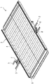
- the figure shows a ramp 1 according to the invention in a three-dimensional representation. It comprises a step-on surface 4 on its upper side, two rails 3 arranged on the side, as well as Laterally aligned forks 2 guided in the rails 3 on each side of the ramp 1.
- the forks 2 each have two arms 5 which delimit an opening 6.
- the openings 6 are designed to receive door leaves of an entry door of a vehicle.
- the arms 5 embrace this accordingly.
- the forks have fixing means 7, here in the form of levers, in order to fix them against further displacement in the respective rail. They can be fixed quickly and easily and removed again with a single movement.
- the ramp 1 is illustrated in a state ready for fixing with the forks 2 in the folded out and aligned.
- the forks 2 can be folded over, so that in a folded-down state they point towards one another and rest on the accessible surface 4 of the ramp 1.
- they each have a hinge joint 8.
- the rails 3 have a C-profile in cross section, the opening of the C-profile being directed upwards. They run parallel to the accessible surface 4 of the ramp. But they can also be aligned to the side.
- the figure also shows that the rails 3 have end delimitations 9 which limit the rails 3 and thus the displaceability of the forks 2 in the rails 3.
Landscapes
- Health & Medical Sciences (AREA)
- Public Health (AREA)
- Engineering & Computer Science (AREA)
- Mechanical Engineering (AREA)
- Life Sciences & Earth Sciences (AREA)
- Animal Behavior & Ethology (AREA)
- General Health & Medical Sciences (AREA)
- Veterinary Medicine (AREA)
- Vehicle Step Arrangements And Article Storage (AREA)
- Auxiliary Methods And Devices For Loading And Unloading (AREA)
Abstract
Description
- Die Erfindung betrifft eine Rampe für ein Fahrzeug des öffentlichen Personenverkehrs zur Überbrückung eines Spalts zwischen einem Einstiegsbereich des Fahrzeugs und einer landseitigen, ortsfesten Plattform, wobei die Rampe zum Auflegen auf die Plattform und auf einen Fußboden im Einstiegsbereich des Fahrzeugs ausgebildet ist. Darüber hinaus betrifft die Erfindung ein Fahrzeug des öffentlichen Personenverkehrs sowie ein Verfahren zum Betreiben der Rampe und des Fahrzeugs.
- Bei Fahrzeugen des öffentlichen Personenverkehrs, insbesondere bei Schienenfahrzeugen werden Rampen eingesetzt, um beispielsweise Rollstuhlfahrern den Einstieg in das Schienenfahrzeug zu vereinfachen oder gar überhaupt erst zu ermöglichen. Die Rampen dienen zu Überbrückung eines Spalts zwischen dem Einstiegsbereich des Fahrzeugs und einem Bahnsteig sowie zum Herstellen eines stufenlosen Einstiegs in das Fahrzeug, auch wenn eine Fußbodenoberkante des Einstiegsbereichs des Schienenfahrzeugs höher oder niedriger liegt als die Bahnsteigkante.
- Dazu sind mobile, manuell auszulegende Rampen bekannt geworden, die nach den Vorschriften der TSI PRM (Technical specification of interoperability "persons with reduced mobility") gegen Wegrutschen zu sichern sind.
- So lehrt die Druckschrift
DE 10 2011 004 453 A1 eine derartige Rampe mit an ihren Seitenkanten angeordneten C-Schienen und darin geführten Nutensteinen. Die Nutensteine sind ihrerseits mit fest im Fahrzeug angeordneten Sicherungsbügeln verbindbar, so dass die Nutensteine in den C-Schienen verklemmt sind und die Rampe gesichert ist. - Die
DE 10 2011 005 238 A1 offenbart ebenfalls eine Rampe mit Befestigungsarmen, die an verschiedenen Positionen seitlich an der Rampe befestigbar sind. Darüber hinaus sind die Befestigungsarme an bodenseitig im Fahrzeug fest verankerten, korrespondieren Mitteln verbindbar. - Das Dokument
JP-A-09-194039 - Der Erfindung liegt die Aufgabe zugrunde, eine einfach und schnell anzubringende Rampe unter Beibehaltung geringer Taktzeiten vorzuschlagen.
- Gelöst wird die Aufgabe durch die Gegenstände der unabhängigen Patentansprüche 1, 8 und 12. Weiterbildungen und Ausgestaltungen der Erfindung finden sich in den Merkmalen der abhängigen Patentansprüche wieder.
- Eine erfindungsgemäße Rampe für ein Fahrzeug des öffentlichen Personenverkehrs, insbesondere für ein Schienenfahrzeug, zur, insbesondere stufenlosen, Überbrückung eines Spalts zwischen einem Einstiegsbereich des Fahrzeugs und einer landseitigen, ortsfesten Plattform, insbesondere einem Bahnsteig, ist zum Auflegen auf die Plattform einerseits und auf einen Fußboden im Einstiegsbereich des Fahrzeugs andererseits ausgebildet und umfasst zur Fixierung der Rampe am Fahrzeug wenigstens eine, im Bereich einer Seite der Rampe angeordnete, seitlich ausgerichtete Gabel zum Umgreifen eines Türflügels einer Einstiegstür des Fahrzeugs.
- Die Gabel ist zum Umgreifen eines Türflügels einer Einstiegstür des Fahrzeugs gemäß einer Weiterbildung U-förmig ausgebildet. Eine U-förmig ausgebildete Gabel umfasst eine von zwei Armen begrenzte Öffnung, welche im fixierungsfertigen Zustand der Rampe zur Fixierung der Rampe und damit zur Sicherung der Rampe gegen Wegrutschen im Einstiegsbereich des Fahrzeugs nach außen weisen und somit von einer betretbaren Fläche der Rampe weg gerichtet sind, um den Türflügel der Einstiegstür des Fahrzeugs in der Öffnung zwischen den Armen aufzunehmen.
- Die Öffnung der Gabel, also der Abstand ihrer die Öffnung begrenzenden Arme, ist weitergebildet angepasst an eine vorgegebene Dicke des Türflügels der Einstiegstür.
- Gemäß einer weiteren Weiterbildung der Erfindung weist die Rampe wenigstens eine im Bereich einer Seite der Rampe angeordnete Schiene zum Führen der Gabel zumindest entlang eines Abschnitts der Rampe auf, wodurch die Gabel entlang des Abschnitts der Rampe verschiebbar an dieser angeordnet ist.
- Weitergebildet ist die Schiene als C-Schiene ausgeführt. Die Schiene weist ein C-förmiges Profil mit einer Öffnung auf, die beispielsweise nach außen, von der Rampe wegweisend gerichtet ist. Die Gabel wird darin beispielsweise mittels eines Nutensteins geführt. Die Schiene kann beidseitig jeweils eine Endbegrenzung aufweisen. Um die Gabel in der Schiene zu arretieren und gegen Verschiebung zu blockieren können Fixierungsmittel, beispielsweise Klemmmittel, wie sie bereits aus dem Stand der Technik bekannt sind, vorgesehen sein. Der im C-Profil eingelegte Nutenstein kann ein Innengewinde aufweisen, das Fixierungsmittel einen Drehgriff mit Außengewinde, die Gabel eine Durchgangsöffnung zum Hindurchführen des Außengewindes des Drehgriffs. Im fest angezogenen Zustand ist die Gabel zwischen Nutenstein und Drehgriff festgeklemmt sowie durch die Klemmung des Nutensteins in der Schiene arretiert. Erst wenn die Gabel gegen Verschieben entlang der Rampe an dieser arretiert ist, ist die Rampe durch das Umgreifen des Türflügels der Einstiegstür des Fahrzeugs am Fahrzeug festgestellt.
- Neben der Anpassung an unterschiedliche Fahrzeuge mit voneinander verschiedenen Einstiegsbereichen hat die Verschiebbarkeit der Gabel den Vorteil, dass die Rampe sowohl für Fahrzeuge mit ebenem Einstiegsbereich als auch für Fahrzeuge mit Stufen im Einstiegsbereich geeignet ist. So lässt sich die Rampe auf einem ebenen Fußboden des Fahrzeugs ohne vertikalen Versatz auflegen und gleichzeitig an der vom Fußboden in horizontaler Richtung entfernten Einstiegstür gegen Wegrutschen sichern. Dennoch werden die dazwischenliegenden Stufen mit der Rampe überbrückt.
- Eine weitere Weiterbildung sieht vor, dass die Rampe im Bereich beider Seiten jeweils eine Gabel aufweist. Die Rampe kann entsprechend im Bereich beider Seiten der Rampe jeweils eine Schiene zum Führen der jeweiligen Gabel zumindest entlang eines Abschnitts der Rampe aufweisen. Nachfolgende Ausführungen betreffend eine Gabel respektive eine Schiene gelten entsprechend auch für Ausführungsformen mit zwei Gabeln und/oder Schienen.
- In einer weiteren Weiterbildung ist die Gabel umklappbar, insbesondere einklappbar, ausgebildet, so dass sie in einem umgeklappten Zustand und in einer Projektion senkrecht zur Rampe in der projizierten Fläche der Rampe liegt. Insbesondere liegt die Gabel im umgeklappten Zustand auf der Rampe, insbesondere auf der betretbaren Fläche der Rampe, welche eine Oberseite der Rampe bildet, oder auf einer dieser gegenüberliegenden Unterseite, auf. Dazu weist die Gabel wenigstens ein Gelenk auf, um welches sie umklappbar ist. Zum Verstauen im Fahrzeug nimmt die Rampe somit weniger Raum ein und weist zum Transport keine herausstehenden Gabeln als Gefahrenquelle auf.
- Im ausgeklappten, ausgerichteten Zustand der Gabel und somit in einem fixierungsfertigen Zustand der Rampe weist die Öffnung der Gabel von der Rampe weg. Sie liegt beispielsweise in einer Ebene mit der betretbaren Fläche der Rampe. Im eingeklappten Zustand hingegen kann die Gabel in einer Ebene parallel zur betretbaren Fläche der Rampe liegen, weist jedoch in die entgegengesetzte Richtung. In diesem Fall ist die Gabel um 180° umklappbar.
- Alternativ kann die Schiene umklappbar ausgebildet sein. Die Schiene ist über ein Gelenk umklappbar an der Rampe angeordnet.
- Gemäß einer weiteren Weiterbildung ist die Gabel um ihre Symmetrieachse drehbar ausgebildet. Somit können größere Winkel der Rampe ausgeglichen werden. Die Gabel kann dennoch waagerecht ausgerichtet werden.
- In einer weiteren Variante ist die Gabel drehbar und klappbar ausgebildet, so dass sie in einem verdrehten und eingeklappten Zustand die Rampe umgreift.
- Ein erfindungsgemäßes Fahrzeug des öffentlichen Personenverkehrs, insbesondere ein Schienenfahrzeug, umfasst wenigstens eine Einstiegstür, insbesondere eine doppelflügelige Einstiegstür, insbesondere eine Schiebe-, Schwenk- oder Schwenk-Schiebetür, und eine Türsteuerung zur Steuerung der Einstiegstür, insbesondere zur Steuerung ihrer Öffnungs- und Schließbewegung, wobei die Türsteuerung ausgebildet ist, die Einstiegstür in einem vorgegebenen Betriebsmodus, insbesondere aus einer vollständig geöffneten Stellung, nur bis zu einer vorgegebenen, teilweise geöffneten Stellung zu schließen und in der teilweise geöffneten Stellung zu halten.
- Bei einer doppelflügeligen Einstiegstür wird die Rampe ungefähr in die Mitte zwischen die zwei Türflügel platziert. Die Türflügel werden von den Gabeln auf beiden Seiten der Rampe umgriffen. Eine Rampe mit beidseitig seitlich angeordneten Gabeln kann aber auch bei einer einflügeligen Einstiegstür eingesetzt werden. Dann greift die dem Türflügel zugewandte Gabel nur um einen Türflügel. Die Gabel auf der anderen Seite greift dann beispielsweise um einen Pfosten eines Türrahmens. Sie kann entsprechend ausgebildet sein zum Umgreifen des Pfostens, insbesondere ist die Öffnung der Gabel, also der Abstand ihrer die Öffnung begrenzenden Arme, angepasst an eine vorgegebene Dicke des Pfostens des Türrahmens der Einstiegstür. Wie oben bereits ausgeführt, kann die Rampe aber bereits mit einer an oder gar auf nur einer Seite der Rampe angeordneten, seitlich ausgerichteten Gabel am Fahrzeug fixiert werden.
- In einem weitergebildeten Fahrzeug kann die Türsteuerung eine manuell betätigbare Steuerungseinheit zur Auswahl des Betriebsmodus durch Fahrzeugpersonal aufweisen. Die manuell zu betätigende Steuerungseinheit kann von der Türsteuerung abgesetzt im Fahrzeug für Fahrzeugpersonal frei zugänglich angeordnet sein. Es handelt sich dann um eine örtlich getrennte Einrichtung, z.B. um einen Schalter, welche mit der Türsteuerung in geeigneter Art und Weise, insbesondere elektrisch, verbunden ist. Die Steuerungseinheit ist geeignet ausgebildet zur manuellen Auswahl des Betriebsmodus durch Fahrzeugpersonal.
- Die Steuerungseinheit ist insbesondere im Bereich der Einstiegstür angeordnet und erlaubt somit dem Fahrzeugpersonal, welches auch die Rampe im Einstiegsbereich und auf der Plattform platziert, den Betriebsmodus der Einstiegstür manuell auszuwählen.
- Im normalen Betrieb würde die Einstiegstür sich automatisch auf vollständig geöffneter Stellung wieder vollständig schließen. Würde ein Gegenstand in der Türöffnung erkannt, welcher die Schließbewegung blockiert, würde die Einstiegstür sich zunächst wieder automatisch öffnen, um ein Einklemmen des Gegenstands zu verhindern.
- Im vorgegebenen Betriebsmodus hingegen wird die Einstiegstür nur teilweise, bis zu einem vorgegebenen Maß geschlossen und ohne weitere Öffnungs- und Schließbewegung in der Position gehalten.
- Dabei kann die Türsteuerung ausgebildet sein, eine Schließbewegung der Einstiegstür durch manuelle Betätigung der Steuerungseinheit zu starten und zu beenden.
- Die manuell zu betätigende Steuerungseinheit ist entsprechend geeignet eingerichtet. Beispielsweise ist sie als Schloss ausgebildet. Das Fahrzeugpersonal kann mittels eines Schlüssels die Schließbewegung der Einstiegstür manuell steuern. Die Einstiegstür wird langsam von Hand zugefahren.
- Alternativ ist die Türsteuerung weitergebildet ausgebildet, eine Schließbewegung der Einstiegstür im vorgegebenen Betriebsmodus zu beenden, wenn bei ausgeführter Schließbewegung eine der Schließbewegung entgegenwirkende Kraft ein vorgegebenes Maß übersteigt.
- Das Fahrzeugpersonal richtet die Rampe aus und wählt den vorgegebenen Betriebsmodus der Einstiegstür manuell aus. Anschließend schließt die Einstiegstür automatisch, öffnet aber nicht beim Erfassen einer der Schließbewegung entgegenwirkenden Kraft, die das vorgegebene Maß übersteigt, welche von der Rampe als Hindernis bewirkt wird, sondern stoppt die Schließbewegung automatisch und verharrt in der teilweise geschlossenen Stellung. Der Einklemmschutz ist im vorgegebenen Betriebsmodus geändert.
- Die Erfassung eines Gegenstands in der Türöffnung, welcher die Schließbewegung blockiert, ist aus dem Stand der Technik grundsätzlich bekannt. So können Hallsensoren in einem Antriebsmotor für die Öffnungs- und Schließbewegung vorgesehen sein, oder der Motorstrom des Antriebsmotors wird überwacht.
- In einer anderen Variante wird der vorgegebene Betriebsmodus von der Türsteuerung erkannt, wenn die der Schließbewegung entgegenwirkende Kraft das vorgegebene Maß übersteigt, wenn sich die Einstiegstür in der teilweise geöffneten Stellung befindet, insbesondere innerhalb eines vorgegebenen Intervalls. Die Türsteuerung ist entsprechend geeignet ausgebildet zur Ermittlung eines Betriebsmodus in Abhängigkeit einer Stellung der Einstiegstür und in Abhängigkeit einer der Schließbewegung entgegenwirkenden Kraft.
- Sobald die Kraft zum Schließen der Einstiegstür, beispielsweise ein Antriebsmoment oder ein Motorstrom des Antriebsmotors, in Abhängigkeit von der Position der Einstiegstür einen bestimmten Grenzwert überschreitet, wird die Schließbewegung gestoppt. Auch in dieser Ausprägung der Erfindung wird die Einstiegstür nicht automatisch wieder geöffnet, sondern ohne weitere Öffnungs- und Schließbewegung in der teilweise geschlossenen Stellung gehalten.
- Ein erfindungsgemäßes Verfahren zum Betreiben einer erfindungsgemäßen Rampe sowie eines erfindungsgemäßen Fahrzeugs umfasst folgende Verfahrensschritte:
- a. Auflegen der Rampe auf die Plattform und auf einen Fußboden im Einstiegsbereich des Fahrzeugs bei geöffneter Einstiegstür des Fahrzeugs und
- b. Ausrichten der Gabel in Verlängerung eines Türflügels der Einstiegstür;
- c. Schließen des Türflügels der Einstiegstür bis zu einer vorgegebenen, teilweise geöffneten Stellung, so dass die Gabel den Türflügel der Einstiegstür umgreift;
- d. Halten des Türflügels der Einstiegstür in der vorgegebenen, teilweise geöffneten Stellung zur Fixierung der Rampe.
- Vor dem Ausbringen und Ausrichten der Rampe wird natürlich die Einstiegstür beim Halt des Fahrzeugs geöffnet. Bei eingeklappter Gabel wird diese vorher ausgeklappt. Bei einer in einer Schiene entlang der Rampe verschiebbar geführten Gabel wird diese bei ausgerichteter Rampe entsprechend an eine Position verschoben, um fluchtend zum komplementären Türflügel der Einstiegstür ausgerichtet zu sein. Anschließend wird die Gabel festgestellt und somit gegen weiteres Verschieben in der Schiene gesichert. In einem weitergebildeten Verfahren wird entsprechend zur Ausführung des Verfahrensschritts b. die Gabel entlang einer im Bereich einer Seite der Rampe angeordneten Schiene zum Führen der Gabel zumindest entlang eines Abschnitts der Rampe verschoben und anschließend an dieser arretiert, beispielsweise festgeklemmt. Der nur teilweise geschlossene, wenigstens eine Türflügel wird von der Gabel der Rampe umgriffen, wodurch die Rampe am Fahrzeug fixiert ist.
- Gemäß einer Weiterbildung des Verfahrens wird vor dem Verfahrensschritt c. ein vorgegebener Betriebsmodus der Einstiegstür manuell ausgewählt wird und/oder die Schließbewegung des Türflügels wird bei der Ausführung des Verfahrensschritts c. manuell durch Betätigung einer Steuerungseinheit einer Türsteuerung gesteuert. Es erfolgt beispielsweise ein manuelles Umschalten vom automatischen zum manuellen Ausführen der Schließbewegung.
- Eine andere Weiterbildung ist hingegen darin zu sehen, dass bei der Ausführung des Verfahrensschritts c. eine der Schließbewegung des Türflügels entgegenwirkende Kraft erfasst wird und die Schließbewegung gestoppt wird, wenn sich die Einstiegstür in der teilweise geöffneten Stellung befindet und wenn die erfasste, der Schließbewegung des Türflügels entgegenwirkende Kraft ein vorgegebenes Maß übersteigt.
- Die Rampe und das Fahrzeug sind jeweils geeignet ausgebildet zur Ausführung des erfindungsgemäßen Verfahrens. Sie umfassen die hierfür bereits genannten, zur Ausführung der jeweiligen Verfahrensschritte geeigneten Mittel.
- Die Erfindung lässt zahlreiche Ausführungsformen zu. Sie wird anhand der nachfolgenden Figur näher erläutert, in der ein Ausgestaltungsbeispiel dargestellt ist.
- Die Figur zeigt eine erfindungsgemäße Rampe 1 in dreidimensionaler Darstellung. Sie umfasst eine betretbare Fläche 4 auf ihrer Oberseite, zwei seitliche angeordnete Schienen 3, sowie in den Schienen 3 geführte, seitlich ausgerichtete Gabeln 2 auf jeder Seite der Rampe 1.
- Die Gabeln 2 weisen jeweils zwei Arme 5 auf, welche eine Öffnung 6 begrenzen. Die Öffnungen 6 sind ausgebildet zur Aufnahme von Türflügeln einer Einstiegstür eines Fahrzeugs. Die Arme 5 umgreifen diese entsprechend.
- Darüber hinaus weisen die Gabeln Fixierungsmittel 7 auf, hier in Form von Hebeln, um sie gegen weitere Verschiebung in der jeweiligen Schiene festzustellen. Sie sind schnell und einfach fixierbar und wieder mit einem Handgriff lösbar.
- Die Rampe 1 ist in einem fixierungsfertigen Zustand mit Im ausgeklappten, ausgerichteten Gabeln 2 veranschaulicht. Zusätzlich sind die Gabeln 2 umklappbar, so dass sie in einem umgeklappten Zustand zueinander weisen und auf der betretbaren Fläche 4 der Rampe 1 aufliegen. Hierzu weisen sie jeweils ein Scharniergelenk 8 auf.
- Die Schienen 3 weisen ein C-Profil im Querschnitt auf, wobei die Öffnung des C-Profils nach oben gerichtet ist. Sie verlaufen parallel zur betretbaren Fläche 4 der Rampe. Sie können aber auch zur Seite ausgerichtet sein.
- Weiter ist in der Figur dargestellt, dass die Schienen 3 Endbegrenzungen 9 aufweisen, welche die Schienen 3 und damit die Verschiebbarkeit der Gabeln 2 in den Schienen 3 begrenzen.
Claims (15)
- Rampe (1) für ein Fahrzeug des öffentlichen Personenverkehrs zur Überbrückung eines Spalts zwischen einem Einstiegsbereich des Fahrzeugs und einer landseitigen, ortsfesten Plattform, wobei die Rampe (1) zum Auflegen auf die Plattform und auf einen Fußboden im Einstiegsbereich des Fahrzeugs ausgebildet ist,
dadurch gekennzeichnet,
dass die Rampe (1) zur Fixierung der Rampe (1) am Fahrzeug wenigstens eine, im Bereich einer Seite der Rampe (1) angeordnete, seitlich ausgerichtete Gabel (2) zum Umgreifen eines Türflügels einer Einstiegstür des Fahrzeugs aufweist. - Rampe (1) nach Anspruch 1,
dadurch gekennzeichnet,
dass die Rampe (1) wenigstens eine im Bereich der Seite angeordnete Schiene (3) zum Führen der Gabel (2) zumindest entlang eines Abschnitts der Rampe (1) aufweist. - Rampe (1) nach Anspruch 2,
dadurch gekennzeichnet,
dass die Schiene (3) als C-Schiene ausgebildet ist. - Rampe (1) nach einem der Ansprüche 1 bis 3,
dadurch gekennzeichnet,
dass die Gabel (2) zum Umgreifen eines Türflügels einer Einstiegstür des Fahrzeugs U-förmig ausgebildet ist. - Rampe (1) nach einem der Ansprüche 1 bis 4,
dadurch gekennzeichnet,
dass die Rampe (1) im Bereich beider Seiten jeweils eine Gabel (2) umfasst. - Rampe (1) nach einem der Ansprüche 1 bis 5,
dadurch gekennzeichnet,
dass die Gabel (2) in einer Ebene mit einer betretbaren Fläche der Rampe (1) liegt. - Rampe (1) nach einem der Ansprüche 1 bis 6,
dadurch gekennzeichnet,
dass die Gabel (2) einklappbar ausgebildet ist, so dass sie in einem eingeklappten Zustand und in einer Projektion senkrecht zur Rampe (2) in der projizierten Fläche der Rampe (2) liegt. - Fahrzeug des öffentlichen Personenverkehrs, insbesondere Schienenfahrzeug, mit wenigstens einer Einstiegstür und einer Türsteuerung zur Steuerung der Einstiegstür, dadurch gekennzeichnet, dass die Türsteuerung ausgebildet ist, die Einstiegstür in einem vorgegebenen Betriebsmodus bis zu einer vorgegebenen, teilweise geöffneten Stellung zu schließen und in der teilweise geöffneten Stellung zu halten.
- Fahrzeug nach Anspruch 8,
dadurch gekennzeichnet,
dass die Türsteuerung eine manuell betätigbare Steuerungseinheit zur Auswahl des Betriebsmodus durch Fahrzeugpersonal aufweist. - Fahrzeug nach Anspruch 9,
dadurch gekennzeichnet,
dass die Türsteuerung ausgebildet ist, eine Schließbewegung der Einstiegstür durch manuelle Betätigung der Steuerungseinheit zu starten und zu beenden. - Fahrzeug nach Anspruch 8 oder 9,
dadurch gekennzeichnet,
dass die Türsteuerung ausgebildet ist, eine Schließbewegung der Einstiegstür im vorgegebenen Betriebsmodus zu beenden, wenn bei ausgeführter Schließbewegung eine der Schließbewegung entgegenwirkende Kraft ein vorgegebenes Maß übersteigt. - Verfahren zum Betreiben einer Rampe (1) nach einem der Ansprüche 1 bis 7 und eines Fahrzeugs nach einem der Ansprüche 8 bis 11, gekennzeichnet durch folgende Verfahrensschritte:a. Auflegen der Rampe (1) auf eine Plattform und auf einen Fußboden im Einstiegsbereich des Fahrzeugs bei geöffneter Einstiegstür des Fahrzeugs;b. Ausrichten der Gabel (2) in Verlängerung eines Türflügels der Einstiegstür;c. Schließen des Türflügels der Einstiegstür bis zu einer vorgegebenen, teilweise geöffneten Stellung, so dass die Gabel (2) den Türflügel der Einstiegstür umgreift;d. Halten des Türflügels der Einstiegstür in der vorgegebenen, teilweise geöffneten Stellung zur Fixierung der Rampe (1).
- Verfahren nach Anspruch 12 mit einem Fahrzeug nach einem der Ansprüche 9 oder 10,
dadurch gekennzeichnet,
dass vor dem Verfahrensschritt c. ein vorgegebener Betriebsmodus der Einstiegstür manuell ausgewählt wird und/oder, dass die Schließbewegung des Türflügels bei der Ausführung des Verfahrensschritts c. manuell durch Betätigung einer Steuerungseinheit einer Türsteuerung gesteuert wird. - Verfahren nach Anspruch 12 mit einem Fahrzeug nach Anspruch 11,
dadurch gekennzeichnet,
dass bei der Ausführung des Verfahrensschritts c. eine einer Schließbewegung des Türflügels entgegenwirkende Kraft erfasst wird und die Schließbewegung gestoppt wird, wenn sich die Einstiegstür in der teilweise geöffneten Stellung befindet und wenn die erfasste, der Schließbewegung des Türflügels entgegenwirkende Kraft ein vorgegebenes Maß übersteigt. - Verfahren nach einem der Ansprüche 12 bis 14 zum Betreiben einer Rampe (1) nach einem der Ansprüche 2 bis 7,
dadurch gekennzeichnet,
dass zur Ausführung des Verfahrensschritts b. die Gabel (2) entlang einer im Bereich einer Seite der Rampe (1) angeordneten Schiene (3) zum Führen der Gabel (2) zumindest entlang eines Abschnitts der Rampe (1) verschoben wird.
Applications Claiming Priority (1)
| Application Number | Priority Date | Filing Date | Title |
|---|---|---|---|
| DE102020205509.2A DE102020205509A1 (de) | 2020-04-30 | 2020-04-30 | Arretierbare Rollstuhlrampe |
Publications (4)
| Publication Number | Publication Date |
|---|---|
| EP3904175A2 true EP3904175A2 (de) | 2021-11-03 |
| EP3904175A3 EP3904175A3 (de) | 2022-01-26 |
| EP3904175B1 EP3904175B1 (de) | 2023-08-09 |
| EP3904175C0 EP3904175C0 (de) | 2023-08-09 |
Family
ID=75477945
Family Applications (1)
| Application Number | Title | Priority Date | Filing Date |
|---|---|---|---|
| EP21167868.5A Active EP3904175B1 (de) | 2020-04-30 | 2021-04-12 | Arretierbare rollstuhlrampe |
Country Status (4)
| Country | Link |
|---|---|
| EP (1) | EP3904175B1 (de) |
| DE (1) | DE102020205509A1 (de) |
| ES (1) | ES2963133T3 (de) |
| PL (1) | PL3904175T3 (de) |
Families Citing this family (1)
| Publication number | Priority date | Publication date | Assignee | Title |
|---|---|---|---|---|
| DE102021200631A1 (de) | 2021-01-25 | 2022-07-28 | Siemens Mobility GmbH | Klapptrittanordnung für ein großräumiges Fahrzeug |
Citations (3)
| Publication number | Priority date | Publication date | Assignee | Title |
|---|---|---|---|---|
| JPH09194039A (ja) | 1996-01-22 | 1997-07-29 | Showa Alum Corp | ドックボード |
| DE102011004453A1 (de) | 2011-02-21 | 2012-08-23 | Siemens Aktiengesellschaft | Rampe mit mechanisch variabler Fixierung |
| DE102011005238A1 (de) | 2011-03-08 | 2012-09-13 | Bombardier Transportation Gmbh | Arretierbare Rampe |
Family Cites Families (5)
| Publication number | Priority date | Publication date | Assignee | Title |
|---|---|---|---|---|
| US5540474A (en) * | 1995-06-20 | 1996-07-30 | Holland; Richard T. | Folding ramp for trucks |
| GB9717787D0 (en) | 1997-08-22 | 1997-10-29 | L T I Limited | Access fascilities for vehicles |
| JP3626441B2 (ja) * | 2001-09-13 | 2005-03-09 | 近畿車輌株式会社 | 鉄道車両の側出入口用プラグドア装置 |
| EP2502609A1 (de) * | 2011-03-20 | 2012-09-26 | Reiner Wagner | Einrichtung zur Fixierung mobiler Rampen in Fahrzeugen |
| DE102013200071A1 (de) | 2013-01-04 | 2014-07-10 | Siemens Aktiengesellschaft | Schienenfahrzeugtür |
-
2020
- 2020-04-30 DE DE102020205509.2A patent/DE102020205509A1/de not_active Ceased
-
2021
- 2021-04-12 EP EP21167868.5A patent/EP3904175B1/de active Active
- 2021-04-12 ES ES21167868T patent/ES2963133T3/es active Active
- 2021-04-12 PL PL21167868.5T patent/PL3904175T3/pl unknown
Patent Citations (3)
| Publication number | Priority date | Publication date | Assignee | Title |
|---|---|---|---|---|
| JPH09194039A (ja) | 1996-01-22 | 1997-07-29 | Showa Alum Corp | ドックボード |
| DE102011004453A1 (de) | 2011-02-21 | 2012-08-23 | Siemens Aktiengesellschaft | Rampe mit mechanisch variabler Fixierung |
| DE102011005238A1 (de) | 2011-03-08 | 2012-09-13 | Bombardier Transportation Gmbh | Arretierbare Rampe |
Also Published As
| Publication number | Publication date |
|---|---|
| EP3904175A3 (de) | 2022-01-26 |
| ES2963133T3 (es) | 2024-03-25 |
| DE102020205509A1 (de) | 2021-11-04 |
| EP3904175B1 (de) | 2023-08-09 |
| PL3904175T3 (pl) | 2024-02-12 |
| EP3904175C0 (de) | 2023-08-09 |
Similar Documents
| Publication | Publication Date | Title |
|---|---|---|
| DE2450909B2 (de) | Fernbedienungseinrichtung zum öffnen und Schließen einer Seitentür eines Personenkraftwagens | |
| EP1587701B1 (de) | Schwenkschiebetür für fahrzeuge | |
| WO2014016135A1 (de) | Liftkabine mit wartungsfenster | |
| DE202017100971U1 (de) | Montagevorrichtung zum Einsetzen von Rahmenelementen in Wandöffnungen | |
| EP1916374B1 (de) | Hebe-Schiebe-Tür mit Gleitführung | |
| EP3904175B1 (de) | Arretierbare rollstuhlrampe | |
| DE102009027242B4 (de) | Bewegliche Trennwand | |
| AT512012B1 (de) | Passagierschienenfahrzeug | |
| EP1816298B1 (de) | Schiebe-Falt-Fensterladen | |
| EP1782982A2 (de) | Kraftfahrzeug mit fremdbetätigter Schiebetür und Schließzustandsüberwachung eines Fenstermoduls | |
| EP2489568A2 (de) | Rampe mit mechanisch variabler Fixierung | |
| EP3663158A1 (de) | Trittsystem für ein fahrzeug | |
| EP4087997B1 (de) | Abstellvorrichtung mit torvorrichtung | |
| EP1857085A2 (de) | Ausfahrbare Einstiegsrampe für Fahrzeuge des öffentlichen Personennah- und fernverkehrs | |
| DE102017004719A1 (de) | Vorrichtung für einen gesicherten Bereich in einem Aufzugschacht | |
| DE20215675U1 (de) | Nutzfahrzeug mit längs verschiebbarem Hubdach | |
| DE202011102484U1 (de) | Schließmechanismus für eine mit Kraftunterstützung schließende Schiebetüre | |
| CH687778A5 (de) | Schwenkschiebetuer. | |
| DE102019104161A1 (de) | Fenster für ein Fahrzeug oder einen Container mit einem Verriegelungsmechanismus | |
| DE102011077631A1 (de) | Automatische Schiebetüranlage | |
| EP1965010B1 (de) | Antriebsvorrichtung | |
| DE3929527A1 (de) | Verschluss, insbesondere fuer das faltdach eines fahrzeuges | |
| EP1743611B1 (de) | Ausfahrbare Einstiegsrampe für Fahrzeuge des öffentlichen Personenverkehrs | |
| DE102015120338A1 (de) | Passive Verriegelung für bewegliche Brücken und Verfahren zum passiven Verriegeln einer beweglichen Brücke | |
| DE102011053989B4 (de) | Feuerschutzschiebetor |
Legal Events
| Date | Code | Title | Description |
|---|---|---|---|
| PUAI | Public reference made under article 153(3) epc to a published international application that has entered the european phase |
Free format text: ORIGINAL CODE: 0009012 |
|
| STAA | Information on the status of an ep patent application or granted ep patent |
Free format text: STATUS: THE APPLICATION HAS BEEN PUBLISHED |
|
| AK | Designated contracting states |
Kind code of ref document: A2 Designated state(s): AL AT BE BG CH CY CZ DE DK EE ES FI FR GB GR HR HU IE IS IT LI LT LU LV MC MK MT NL NO PL PT RO RS SE SI SK SM TR |
|
| PUAL | Search report despatched |
Free format text: ORIGINAL CODE: 0009013 |
|
| AK | Designated contracting states |
Kind code of ref document: A3 Designated state(s): AL AT BE BG CH CY CZ DE DK EE ES FI FR GB GR HR HU IE IS IT LI LT LU LV MC MK MT NL NO PL PT RO RS SE SI SK SM TR |
|
| RIC1 | Information provided on ipc code assigned before grant |
Ipc: B65G 69/30 20060101ALI20211223BHEP Ipc: B60R 3/00 20060101ALI20211223BHEP Ipc: A61G 3/06 20060101ALI20211223BHEP Ipc: B61D 23/00 20060101AFI20211223BHEP |
|
| STAA | Information on the status of an ep patent application or granted ep patent |
Free format text: STATUS: REQUEST FOR EXAMINATION WAS MADE |
|
| 17P | Request for examination filed |
Effective date: 20220719 |
|
| RBV | Designated contracting states (corrected) |
Designated state(s): AL AT BE BG CH CY CZ DE DK EE ES FI FR GB GR HR HU IE IS IT LI LT LU LV MC MK MT NL NO PL PT RO RS SE SI SK SM TR |
|
| GRAP | Despatch of communication of intention to grant a patent |
Free format text: ORIGINAL CODE: EPIDOSNIGR1 |
|
| STAA | Information on the status of an ep patent application or granted ep patent |
Free format text: STATUS: GRANT OF PATENT IS INTENDED |
|
| INTG | Intention to grant announced |
Effective date: 20230412 |
|
| GRAS | Grant fee paid |
Free format text: ORIGINAL CODE: EPIDOSNIGR3 |
|
| GRAA | (expected) grant |
Free format text: ORIGINAL CODE: 0009210 |
|
| STAA | Information on the status of an ep patent application or granted ep patent |
Free format text: STATUS: THE PATENT HAS BEEN GRANTED |
|
| AK | Designated contracting states |
Kind code of ref document: B1 Designated state(s): AL AT BE BG CH CY CZ DE DK EE ES FI FR GB GR HR HU IE IS IT LI LT LU LV MC MK MT NL NO PL PT RO RS SE SI SK SM TR |
|
| REG | Reference to a national code |
Ref country code: GB Ref legal event code: FG4D Free format text: NOT ENGLISH |
|
| REG | Reference to a national code |
Ref country code: CH Ref legal event code: EP |
|
| REG | Reference to a national code |
Ref country code: DE Ref legal event code: R096 Ref document number: 502021001179 Country of ref document: DE |
|
| REG | Reference to a national code |
Ref country code: IE Ref legal event code: FG4D Free format text: LANGUAGE OF EP DOCUMENT: GERMAN |
|
| U01 | Request for unitary effect filed |
Effective date: 20230825 |
|
| U07 | Unitary effect registered |
Designated state(s): AT BE BG DE DK EE FI FR IT LT LU LV MT NL PT SE SI Effective date: 20230901 |
|
| PG25 | Lapsed in a contracting state [announced via postgrant information from national office to epo] |
Ref country code: GR Free format text: LAPSE BECAUSE OF FAILURE TO SUBMIT A TRANSLATION OF THE DESCRIPTION OR TO PAY THE FEE WITHIN THE PRESCRIBED TIME-LIMIT Effective date: 20231110 |
|
| PG25 | Lapsed in a contracting state [announced via postgrant information from national office to epo] |
Ref country code: IS Free format text: LAPSE BECAUSE OF FAILURE TO SUBMIT A TRANSLATION OF THE DESCRIPTION OR TO PAY THE FEE WITHIN THE PRESCRIBED TIME-LIMIT Effective date: 20231209 |
|
| PG25 | Lapsed in a contracting state [announced via postgrant information from national office to epo] |
Ref country code: RS Free format text: LAPSE BECAUSE OF FAILURE TO SUBMIT A TRANSLATION OF THE DESCRIPTION OR TO PAY THE FEE WITHIN THE PRESCRIBED TIME-LIMIT Effective date: 20230809 Ref country code: NO Free format text: LAPSE BECAUSE OF FAILURE TO SUBMIT A TRANSLATION OF THE DESCRIPTION OR TO PAY THE FEE WITHIN THE PRESCRIBED TIME-LIMIT Effective date: 20231109 Ref country code: IS Free format text: LAPSE BECAUSE OF FAILURE TO SUBMIT A TRANSLATION OF THE DESCRIPTION OR TO PAY THE FEE WITHIN THE PRESCRIBED TIME-LIMIT Effective date: 20231209 Ref country code: HR Free format text: LAPSE BECAUSE OF FAILURE TO SUBMIT A TRANSLATION OF THE DESCRIPTION OR TO PAY THE FEE WITHIN THE PRESCRIBED TIME-LIMIT Effective date: 20230809 Ref country code: GR Free format text: LAPSE BECAUSE OF FAILURE TO SUBMIT A TRANSLATION OF THE DESCRIPTION OR TO PAY THE FEE WITHIN THE PRESCRIBED TIME-LIMIT Effective date: 20231110 |
|
| REG | Reference to a national code |
Ref country code: ES Ref legal event code: FG2A Ref document number: 2963133 Country of ref document: ES Kind code of ref document: T3 Effective date: 20240325 |
|
| PG25 | Lapsed in a contracting state [announced via postgrant information from national office to epo] |
Ref country code: SM Free format text: LAPSE BECAUSE OF FAILURE TO SUBMIT A TRANSLATION OF THE DESCRIPTION OR TO PAY THE FEE WITHIN THE PRESCRIBED TIME-LIMIT Effective date: 20230809 Ref country code: RO Free format text: LAPSE BECAUSE OF FAILURE TO SUBMIT A TRANSLATION OF THE DESCRIPTION OR TO PAY THE FEE WITHIN THE PRESCRIBED TIME-LIMIT Effective date: 20230809 Ref country code: SK Free format text: LAPSE BECAUSE OF FAILURE TO SUBMIT A TRANSLATION OF THE DESCRIPTION OR TO PAY THE FEE WITHIN THE PRESCRIBED TIME-LIMIT Effective date: 20230809 |
|
| REG | Reference to a national code |
Ref country code: DE Ref legal event code: R097 Ref document number: 502021001179 Country of ref document: DE |
|
| U20 | Renewal fee for the european patent with unitary effect paid |
Year of fee payment: 4 Effective date: 20240418 |
|
| PLBE | No opposition filed within time limit |
Free format text: ORIGINAL CODE: 0009261 |
|
| STAA | Information on the status of an ep patent application or granted ep patent |
Free format text: STATUS: NO OPPOSITION FILED WITHIN TIME LIMIT |
|
| 26N | No opposition filed |
Effective date: 20240513 |
|
| PG25 | Lapsed in a contracting state [announced via postgrant information from national office to epo] |
Ref country code: MC Free format text: LAPSE BECAUSE OF FAILURE TO SUBMIT A TRANSLATION OF THE DESCRIPTION OR TO PAY THE FEE WITHIN THE PRESCRIBED TIME-LIMIT Effective date: 20230809 |
|
| PG25 | Lapsed in a contracting state [announced via postgrant information from national office to epo] |
Ref country code: MC Free format text: LAPSE BECAUSE OF FAILURE TO SUBMIT A TRANSLATION OF THE DESCRIPTION OR TO PAY THE FEE WITHIN THE PRESCRIBED TIME-LIMIT Effective date: 20230809 |
|
| PG25 | Lapsed in a contracting state [announced via postgrant information from national office to epo] |
Ref country code: IE Free format text: LAPSE BECAUSE OF NON-PAYMENT OF DUE FEES Effective date: 20240412 |
|
| U20 | Renewal fee for the european patent with unitary effect paid |
Year of fee payment: 5 Effective date: 20250417 |
|
| PGFP | Annual fee paid to national office [announced via postgrant information from national office to epo] |
Ref country code: PL Payment date: 20250403 Year of fee payment: 5 |
|
| PGFP | Annual fee paid to national office [announced via postgrant information from national office to epo] |
Ref country code: GB Payment date: 20250507 Year of fee payment: 5 |
|
| PGFP | Annual fee paid to national office [announced via postgrant information from national office to epo] |
Ref country code: CZ Payment date: 20250404 Year of fee payment: 5 |
|
| PG25 | Lapsed in a contracting state [announced via postgrant information from national office to epo] |
Ref country code: CY Free format text: LAPSE BECAUSE OF FAILURE TO SUBMIT A TRANSLATION OF THE DESCRIPTION OR TO PAY THE FEE WITHIN THE PRESCRIBED TIME-LIMIT; INVALID AB INITIO Effective date: 20210412 |
|
| PG25 | Lapsed in a contracting state [announced via postgrant information from national office to epo] |
Ref country code: HU Free format text: LAPSE BECAUSE OF FAILURE TO SUBMIT A TRANSLATION OF THE DESCRIPTION OR TO PAY THE FEE WITHIN THE PRESCRIBED TIME-LIMIT; INVALID AB INITIO Effective date: 20210412 |
|
| PGFP | Annual fee paid to national office [announced via postgrant information from national office to epo] |
Ref country code: ES Payment date: 20250721 Year of fee payment: 5 |
|
| PGFP | Annual fee paid to national office [announced via postgrant information from national office to epo] |
Ref country code: CH Payment date: 20250709 Year of fee payment: 5 |
|
| U1H | Name or address of the proprietor changed after the registration of the unitary effect |
Owner name: SIEMENS MOBILITY GMBH; DE |