EP3899375B1 - Vorrichtung und verfahren zum zuführen von flüssigkeit zu einem fluidkreislauf einer heizung oder eines kühlsystems - Google Patents
Vorrichtung und verfahren zum zuführen von flüssigkeit zu einem fluidkreislauf einer heizung oder eines kühlsystems Download PDFInfo
- Publication number
- EP3899375B1 EP3899375B1 EP20713840.5A EP20713840A EP3899375B1 EP 3899375 B1 EP3899375 B1 EP 3899375B1 EP 20713840 A EP20713840 A EP 20713840A EP 3899375 B1 EP3899375 B1 EP 3899375B1
- Authority
- EP
- European Patent Office
- Prior art keywords
- liquid
- vessel
- fluid circuit
- valve
- controller
- Prior art date
- Legal status (The legal status is an assumption and is not a legal conclusion. Google has not performed a legal analysis and makes no representation as to the accuracy of the status listed.)
- Active
Links
Images


Classifications
-
- F—MECHANICAL ENGINEERING; LIGHTING; HEATING; WEAPONS; BLASTING
- F24—HEATING; RANGES; VENTILATING
- F24H—FLUID HEATERS, e.g. WATER OR AIR HEATERS, HAVING HEAT-GENERATING MEANS, e.g. HEAT PUMPS, IN GENERAL
- F24H9/00—Details
- F24H9/0005—Details for water heaters
- F24H9/0042—Cleaning arrangements
-
- C—CHEMISTRY; METALLURGY
- C02—TREATMENT OF WATER, WASTE WATER, SEWAGE, OR SLUDGE
- C02F—TREATMENT OF WATER, WASTE WATER, SEWAGE, OR SLUDGE
- C02F1/00—Treatment of water, waste water, or sewage
- C02F1/008—Control or steering systems not provided for elsewhere in subclass C02F
-
- F—MECHANICAL ENGINEERING; LIGHTING; HEATING; WEAPONS; BLASTING
- F24—HEATING; RANGES; VENTILATING
- F24D—DOMESTIC- OR SPACE-HEATING SYSTEMS, e.g. CENTRAL HEATING SYSTEMS; DOMESTIC HOT-WATER SUPPLY SYSTEMS; ELEMENTS OR COMPONENTS THEREFOR
- F24D19/00—Details
- F24D19/10—Arrangement or mounting of control or safety devices
- F24D19/1006—Arrangement or mounting of control or safety devices for water heating systems
- F24D19/1009—Arrangement or mounting of control or safety devices for water heating systems for central heating
-
- F—MECHANICAL ENGINEERING; LIGHTING; HEATING; WEAPONS; BLASTING
- F24—HEATING; RANGES; VENTILATING
- F24D—DOMESTIC- OR SPACE-HEATING SYSTEMS, e.g. CENTRAL HEATING SYSTEMS; DOMESTIC HOT-WATER SUPPLY SYSTEMS; ELEMENTS OR COMPONENTS THEREFOR
- F24D3/00—Hot-water central heating systems
- F24D3/04—Hot-water central heating systems with the water under high pressure
- F24D3/06—Arrangements or devices for maintaining high pressure
-
- F—MECHANICAL ENGINEERING; LIGHTING; HEATING; WEAPONS; BLASTING
- F24—HEATING; RANGES; VENTILATING
- F24D—DOMESTIC- OR SPACE-HEATING SYSTEMS, e.g. CENTRAL HEATING SYSTEMS; DOMESTIC HOT-WATER SUPPLY SYSTEMS; ELEMENTS OR COMPONENTS THEREFOR
- F24D3/00—Hot-water central heating systems
- F24D3/10—Feed-line arrangements, e.g. providing for heat-accumulator tanks, expansion tanks ; Hydraulic components of a central heating system
- F24D3/1083—Filling valves or arrangements for filling
-
- F—MECHANICAL ENGINEERING; LIGHTING; HEATING; WEAPONS; BLASTING
- F24—HEATING; RANGES; VENTILATING
- F24H—FLUID HEATERS, e.g. WATER OR AIR HEATERS, HAVING HEAT-GENERATING MEANS, e.g. HEAT PUMPS, IN GENERAL
- F24H9/00—Details
- F24H9/40—Arrangements for preventing corrosion
- F24H9/45—Arrangements for preventing corrosion for preventing galvanic corrosion, e.g. cathodic or electrolytic means
-
- C—CHEMISTRY; METALLURGY
- C02—TREATMENT OF WATER, WASTE WATER, SEWAGE, OR SLUDGE
- C02F—TREATMENT OF WATER, WASTE WATER, SEWAGE, OR SLUDGE
- C02F1/00—Treatment of water, waste water, or sewage
- C02F1/30—Treatment of water, waste water, or sewage by irradiation
- C02F1/32—Treatment of water, waste water, or sewage by irradiation with ultraviolet light
-
- C—CHEMISTRY; METALLURGY
- C02—TREATMENT OF WATER, WASTE WATER, SEWAGE, OR SLUDGE
- C02F—TREATMENT OF WATER, WASTE WATER, SEWAGE, OR SLUDGE
- C02F2103/00—Nature of the water, waste water, sewage or sludge to be treated
- C02F2103/02—Non-contaminated water, e.g. for industrial water supply
- C02F2103/023—Water in cooling circuits
-
- C—CHEMISTRY; METALLURGY
- C02—TREATMENT OF WATER, WASTE WATER, SEWAGE, OR SLUDGE
- C02F—TREATMENT OF WATER, WASTE WATER, SEWAGE, OR SLUDGE
- C02F2209/00—Controlling or monitoring parameters in water treatment
- C02F2209/005—Processes using a programmable logic controller [PLC]
- C02F2209/006—Processes using a programmable logic controller [PLC] comprising a software program or a logic diagram
-
- C—CHEMISTRY; METALLURGY
- C02—TREATMENT OF WATER, WASTE WATER, SEWAGE, OR SLUDGE
- C02F—TREATMENT OF WATER, WASTE WATER, SEWAGE, OR SLUDGE
- C02F2209/00—Controlling or monitoring parameters in water treatment
- C02F2209/03—Pressure
-
- C—CHEMISTRY; METALLURGY
- C02—TREATMENT OF WATER, WASTE WATER, SEWAGE, OR SLUDGE
- C02F—TREATMENT OF WATER, WASTE WATER, SEWAGE, OR SLUDGE
- C02F2209/00—Controlling or monitoring parameters in water treatment
- C02F2209/42—Liquid level
-
- C—CHEMISTRY; METALLURGY
- C02—TREATMENT OF WATER, WASTE WATER, SEWAGE, OR SLUDGE
- C02F—TREATMENT OF WATER, WASTE WATER, SEWAGE, OR SLUDGE
- C02F2209/00—Controlling or monitoring parameters in water treatment
- C02F2209/44—Time
-
- C—CHEMISTRY; METALLURGY
- C02—TREATMENT OF WATER, WASTE WATER, SEWAGE, OR SLUDGE
- C02F—TREATMENT OF WATER, WASTE WATER, SEWAGE, OR SLUDGE
- C02F2303/00—Specific treatment goals
- C02F2303/04—Disinfection
-
- C—CHEMISTRY; METALLURGY
- C02—TREATMENT OF WATER, WASTE WATER, SEWAGE, OR SLUDGE
- C02F—TREATMENT OF WATER, WASTE WATER, SEWAGE, OR SLUDGE
- C02F2303/00—Specific treatment goals
- C02F2303/08—Corrosion inhibition
-
- C—CHEMISTRY; METALLURGY
- C02—TREATMENT OF WATER, WASTE WATER, SEWAGE, OR SLUDGE
- C02F—TREATMENT OF WATER, WASTE WATER, SEWAGE, OR SLUDGE
- C02F2307/00—Location of water treatment or water treatment device
- C02F2307/14—Treatment of water in water supply networks, e.g. to prevent bacterial growth
-
- F—MECHANICAL ENGINEERING; LIGHTING; HEATING; WEAPONS; BLASTING
- F24—HEATING; RANGES; VENTILATING
- F24D—DOMESTIC- OR SPACE-HEATING SYSTEMS, e.g. CENTRAL HEATING SYSTEMS; DOMESTIC HOT-WATER SUPPLY SYSTEMS; ELEMENTS OR COMPONENTS THEREFOR
- F24D19/00—Details
- F24D19/0092—Devices for preventing or removing corrosion, slime or scale
-
- F—MECHANICAL ENGINEERING; LIGHTING; HEATING; WEAPONS; BLASTING
- F24—HEATING; RANGES; VENTILATING
- F24D—DOMESTIC- OR SPACE-HEATING SYSTEMS, e.g. CENTRAL HEATING SYSTEMS; DOMESTIC HOT-WATER SUPPLY SYSTEMS; ELEMENTS OR COMPONENTS THEREFOR
- F24D2220/00—Components of central heating installations excluding heat sources
- F24D2220/04—Sensors
- F24D2220/044—Flow sensors
-
- F—MECHANICAL ENGINEERING; LIGHTING; HEATING; WEAPONS; BLASTING
- F24—HEATING; RANGES; VENTILATING
- F24D—DOMESTIC- OR SPACE-HEATING SYSTEMS, e.g. CENTRAL HEATING SYSTEMS; DOMESTIC HOT-WATER SUPPLY SYSTEMS; ELEMENTS OR COMPONENTS THEREFOR
- F24D2220/00—Components of central heating installations excluding heat sources
- F24D2220/04—Sensors
- F24D2220/046—Pressure sensors
-
- F—MECHANICAL ENGINEERING; LIGHTING; HEATING; WEAPONS; BLASTING
- F24—HEATING; RANGES; VENTILATING
- F24D—DOMESTIC- OR SPACE-HEATING SYSTEMS, e.g. CENTRAL HEATING SYSTEMS; DOMESTIC HOT-WATER SUPPLY SYSTEMS; ELEMENTS OR COMPONENTS THEREFOR
- F24D2220/00—Components of central heating installations excluding heat sources
- F24D2220/04—Sensors
- F24D2220/048—Level sensors, e.g. water level sensors
-
- F—MECHANICAL ENGINEERING; LIGHTING; HEATING; WEAPONS; BLASTING
- F24—HEATING; RANGES; VENTILATING
- F24D—DOMESTIC- OR SPACE-HEATING SYSTEMS, e.g. CENTRAL HEATING SYSTEMS; DOMESTIC HOT-WATER SUPPLY SYSTEMS; ELEMENTS OR COMPONENTS THEREFOR
- F24D3/00—Hot-water central heating systems
- F24D3/10—Feed-line arrangements, e.g. providing for heat-accumulator tanks, expansion tanks ; Hydraulic components of a central heating system
- F24D3/1008—Feed-line arrangements, e.g. providing for heat-accumulator tanks, expansion tanks ; Hydraulic components of a central heating system expansion tanks
- F24D3/1033—Feed-line arrangements, e.g. providing for heat-accumulator tanks, expansion tanks ; Hydraulic components of a central heating system expansion tanks with compressed gas cylinder
Definitions
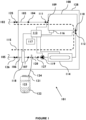
- Apparatus for supplying liquid to a fluid circuit of a heating or a cooling system is shown in Figure 1 .
- the apparatus is usable to supply a liquid from a liquid source to a fluid circuit of a heating or a cooling system.
- the apparatus 101 is utilised to supply a top-up liquid to the fluid circuit of the heating or the cooling system.
- Apparatus 101 is arranged to receive liquid from a liquid source 102, via a fluid conduit 103 connected to the liquid source 102, which may be a mains water supply, in a direction of inflow 104, and to supply liquid to a fluid circuit 105, which may be a fluid circuit of a heating or a cooling system, via a fluid conduit 106 that is connected to the fluid circuit 105, in a direction of outflow 107.
- a liquid source 102 via a fluid conduit 103 connected to the liquid source 102, which may be a mains water supply, in a direction of inflow 104
- a fluid circuit 105 which may be a fluid circuit of a heating or a cooling system
- the apparatus 101 comprises a vessel 108 that defines an inlet port 109, through which liquid can enter the vessel 108 in the direction of inflow 104, and an outlet port 110, through which liquid can exit the vessel 108 in the direction of outflow 107.
- the inlet port 109 is provided with an inlet valve 111, which is located upstream of the inlet port 109 and is operable to prevent or allow a liquid to enter the vessel 108 through the inlet port 109.
- the outlet port 110 is provided with an outlet valve 112, which is located downstream of the outlet port 110 and is operable to prevent or allow a liquid to exit the vessel 108 through the outlet port 110.
- the apparatus 101 further comprises a controller 113.
- the controller 113 is operable to selectively open and close the inlet valve I I I and the outlet valve 112.
- the controller 113 is operable to control steps in a method of supplying liquid to a fluid circuit of a heating or a cooling system, for example top-up liquid.
- a method of supplying liquid from the liquid source 102 to the fluid circuit 105 in a first step, with the outlet valve 112 closed and the inlet valve 111 open, liquid enters into the vessel 108 from the liquid source 102; in a second step, the inlet valve 111 is closed; in a third step, the outlet valve 112 is opened and, with the outlet valve 110 open and the inlet valve 111 closed, the liquid that entered the vessel 108 during the first step exits the vessel 108; in a fourth step, the outlet valve 112 is closed, creating a "break" between the inlet valve I I I (on the liquid source 102 side) and the outlet valve 112 (on the fluid circuit 105 side) by means of the vessel 108 being empty of liquid.
- the inlet valve 111 is opened and the first step commences again.
- the vessel 108 is used to create an air gap to inhibit undesirable backflow of liquid into the liquid source 102, which is especially important when the liquid source 102 is a mains water supply.
- the light source 114 located between the outlet valve 112 and the fluid circuit 105 and, as such, is configured to emit ultraviolet light incident on liquid flowing from the vessel 108 to the fluid circuit 105.
- the light source 114 may be sited at any suitable location to ensure that liquid from the liquid source 102 is subjected to UV light emitted therefrom before entering the fluid circuit 105.
- the light source 114 may be located between the liquid source 102 and the inlet valve 111 and, as such, be configured to emit ultraviolet light incident on liquid flowing into the vessel 108 from the liquid source 102.
- the light source 114 can be located to emit ultraviolet light incident on liquid within the vessel 108.
- the light source 114 may be any suitable light source.
- the light source 114 may comprise only one or more than one UV light emitting lamps, of any suitable type.
- the light source 114 may have any suitable shape and dimensions. It is to be appreciated that any physical barrier between a UV light emitting lamp of the light source 114 and liquid to be treated by the UV light will allow an appropriate transmission of the desired light wavelength or wavelengths therethrough. It is hence to be understood that the selection of a material or materials for defining a conduit through which liquid can travel will involve the identification of a material having suitable light transmittance properties.
- the controller 113 is also in communication with the light source 114, to selectively power the light source at an appropriate step or steps in a method of supplying liquid from the liquid source 102 to the fluid circuit 105.
- the controller 113 may be any suitable device, for example a programmable logic controller (PLC).
- PLC programmable logic controller
- the controller 113 may comprise, or otherwise have access to, a non-transitory computer-readable medium, with program instructions being stored on the non-transitory computer-readable medium that are executable by the controller to cause the controller to perform each of a plurality of functions.
- a heating or a cooling system comprising a fluid circuit may comprise the apparatus 101.
- the apparatus 101 may be used to provide top-up fluid to the fluid circuit of the heating or the cooling system.
- the apparatus 101 may be used to provide top-up fluid from a coldwater main supply to a fluid circuit of a heating or a cooling system.
- the apparatus 101 may be used to maintain a desired pressurisation of a fluid circuit. It is therefore to be appreciated that other components may be present within a system comprising the apparatus 101.
- a method of supplying a liquid to a heating or a cooling system comprising a fluid circuit comprises the steps of, with reference to Figure 1 :
- the apparatus 101 may be in a non-supplying mode of operation ("air-break” mode) or in a supplying mode of operation (“filling" mode).
- the mode of operation of the apparatus 101 is the non-supplying mode of operation ("air-break” mode) unless the supplying mode of operation ("filling" mode) is initiated.
- step 202 an air-filled interruption ("air-break") between the liquid source 102 and the fluid circuit 105 is maintained.
- Both the inlet valve 111 and the outlet valve 112 are closed, and the vessel 108 is empty of liquid.
- the air in the vessel 108 provides a "break" in the flow path 115 between the liquid source 102 and the fluid circuit 105.
- step 203 a question is asked as to whether liquid is to be supplied to the fluid circuit 105. If the question asked at step 203 is answered in the negative, step 202 is again entered.
- step 204 is entered.
- step 204 represents the apparatus 101 switching from a non-supplying mode of operation ("air-break” mode) into a supplying mode of operation ("filling" mode).
- step 204 the inlet valve 111 is opened. This allows liquid to flow from the liquid source 102 into the vessel 108, which fills, during step 205, because the outlet valve 112 is still closed.
- step 206 is entered.
- step 206 the inlet valve 111 is closed and the outlet valve 112 is opened. This allows liquid to flow from the vessel 108, which empties, during step 207, because the inlet valve 111 is now closed.
- step 208 is entered.
- step 208 the outlet valve 112 is closed. Both the inlet valve 111 and the outlet valve 112 are now closed.
- step 209 a question is asked as to whether more liquid is to be supplied to the fluid circuit 105. If the question asked at step 203 is answered in the affirmative, step 204 is again entered.
- step 202 is entered.
- step 202 represents the apparatus 101 switching from the supplying mode of operation ("filling" mode) back into the non-supplying mode of operation ("air-break” mode).
- Figure 3 shows apparatus 101 for supplying a liquid from a liquid source to a fluid circuit within a heating system 301 comprising fluid circuit 105.
- Heating system 301 comprises a heat source 303, such as a boiler, and at least one heat emitter 304, such as a radiator.
- a main system flow pipe 305 extends from the heat source 303 to the at least one heat emitter 305, and a main system return pipe 306 extends from the at least one heat emitter 304 to the heat source 303.
- Heating system 301 comprises a system pump 307, which is disposed along main system flow pipe 305 between the heat source 303 and the at least one heat emitter 304, and which is operable to circulate system liquid around the fluid circuit 105 in the direction of circulating flow 302.
- heating system 301 further comprises an expansion vessel 308, which is disposed along main system return pipe 306 between at least one heat emitter 304 and the heat source 303.
- Apparatus 101 is arranged to receive liquid via the fluid conduit 103 connected to liquid source 102, in the direction of inflow 104, and to supply liquid to the fluid circuit 105 via the fluid conduit 106 that is connected to the main system return pipe 306, in a direction of outflow 107.
- the liquid supplied to the fluid circuit 105 of the heating system 301 by the apparatus 101 may be a flow of top-up liquid to the fluid circuit 301.
- the apparatus 101 for supplying a liquid from a liquid source to a fluid circuit may be used within a cooling system comprising fluid circuit 105.
- apparatus for supplying a liquid to a heating or a cooling system comprising a fluid circuit comprises, with reference to Figure 1 :
- the apparatus 101 further comprises a light source 114 operable to emit ultraviolet light incident on a liquid flowing along a flow path 115 between the liquid source 102 and the fluid circuit 105, the flow path 115 extending through the vessel 108.
- the light source 114 is operable to emit ultraviolet light incident on a liquid flowing along the flow path 115 at a position that is downstream of the outlet port 110 of the vessel 108.
- the controller 113 is operable to selectively turn the light source 114 on and off, and the program instructions stored on the non-transitory computer-readable medium are executable by the controller 113 to cause the controller 113 to: maintain the light source 114 in an off condition during the non-supplying mode of operation, and maintain the light source 114 in an on condition during the supplying mode of operation.
- a determination that vessel 108 has filled to a sufficient extent may be made based on a reading output to the controller 113 from a sensing arrangement 116 for providing an indication as to the level of liquid within the vessel 108 and/or on a signal generated by a timer (not shown) comprised by the controller 113.
- a determination that vessel 108 has emptied to a sufficient extent may be made based on a reading output to the controller 113 from a sensing arrangement 116 for providing an indication as to the level of liquid within the vessel 108 and/or on a signal generated by a timer (not shown) comprised by the controller 113.
- the duration of the first period of time may be the length of time taken before a sensing arrangement 116 indicates that the vessel 108 has filled up to a predetermined extent of filling or may be a predetermined duration monitored by a timer 117, this duration having previously been calculated to be adequate to allow the vessel 108 to fill to a suitable extent
- the second period of time may be the length of time taken before a sensing arrangement 116 indicates that the vessel 108 has drained down to a predetermined extent of draining or may be a predetermined duration monitored by a timer 117, this duration having previously been calculated to be adequate to allow the vessel 108 to empty to a suitable extent.
- the sensing arrangement 116 may comprise any suitable number of sensors, the or each being of any suitable type and the or each being sited at any suitable position.
- the sensing arrangement 116 comprises a first sensor at a first position for detecting that the vessel 108 has filled completely or otherwise to a maximum extent, and a second sensor at a second, different position for detecting that the vessel 108 has emptied completely or otherwise to a minimum extent.
- the sensing arrangement 116 comprises a pressure sensor at a suitable position.
- the controller 113 is configured to receive an input from a pressure sensing arrangement 118 for providing an indication as to the pressure of system liquid within the fluid circuit 105.
- the pressure sensing arrangement 118 may comprise any suitable number of sensors, the or each being of any suitable type and the or each being sited at any suitable position.
- a pressure sensor of the pressure sensing arrangement 118 may be located within the flow path 115 (as shown in Figure 1 ) or alternatively the fluid circuit 105.
- the apparatus 101 comprises the pressure sensing arrangement 118.
- the pressure sensing arrangement 118 is within the flow path 115 and, in this example, is positioned downstream of the light source 114.
- Initiation of the supplying mode may be made based on a reading output to the controller from a pressure sensing arrangement for providing an indication as to the pressure of system liquid within a connected fluid circuit.
- Apparatus 101 functions to assist system liquid of a fluid circuit of a heating or a cooling system to be maintained at a desired pressure.
- Steps in a method of supplying a liquid to a fluid circuit of a heating or a cooling system will now be described.
- a pressure level of system liquid in the fluid circuit is measured to obtain a pressure level indication.
- This pressure level indication is then compared with a pressure level threshold, which is associated with a desired pressure of system liquid, to determine whether the pressure level indication is below the pressure level threshold.
- the previous steps of measuring a pressure level of system liquid in the fluid circuit to obtain a pressure level indication and then comparing this pressure level indication with the pressure level threshold to determine whether the pressure level indication exceeds the pressure level threshold are repeated.
- an activation signal is generated to initiate a supplying mode to supply liquid from the liquid source to the connected fluid circuit.
- the pressure level of system liquid in the fluid circuit is measured and when a drop in the system liquid pressure is detected, the supplying mode is initiated to restore the system liquid pressure to a desired operating pressure level.
- the supplying mode may be initiated if any pressure drop is detected or only if a pressure drop of a predetermined extent has been detected.
- step 203 at which a question is asked as to whether or not liquid is to be supplied to the fluid circuit (with step 202 being re-entered if the question is answered in the negative, if a pressure drop has not been detected or a predetermined extent of a pressure drop has not been detected, and with step 204 being entered if the question is answered in the affirmative, if a pressure drop has been detected or a predetermined extent of a pressure drop has been detected).
- a pressure level of system liquid is then measured to obtain a subsequent pressure level indication.
- This subsequent pressure level of system liquid is then compared with the pressure level threshold to determine whether the subsequent pressure level indication is below the pressure level threshold.
- the previous steps of measuring a pressure level of system liquid in the fluid circuit and then comparing this pressure level indication with the pressure level threshold to determine whether the pressure level indication is below the pressure level threshold are repeated.
- the supplying mode is again initiated.
- the pressure level of system liquid in the fluid circuit is measured and when the desired operating pressure level has been reached, with the system liquid topped-up properly, the non-supplying mode is entered and the pressure level of system liquid in the fluid circuit is monitored to detect a drop in the system liquid pressure; however, if the desired operating pressure level has not been reached, with further topping-up of the system liquid required, the supplying mode is again entered.
- step 209 at which a question is asked as to whether or not more liquid is to be supplied to the fluid circuit (with step 202 being re-entered if the question is answered in the negative, if restoration to the desired operating pressure has been detected, and with step 204 being entered if the question is answered in the affirmative, if restoration to the desired operating pressure has not been detected).
- the step of entering the supplying mode from the non-supplying mode involves the controller 113 switching on the light source 114 to begin emitting UV light and the step of entering the non-supplying mode from the supplying mode involves the controller 113 switching off the light source 114 to stop emitting UV light.
- the apparatus 101 further comprises a pump 119, which is operable to move liquid from the vessel 108 along the flow path 115 towards the fluid circuit 105.
- the pump 119 may be any suitable type and sited at any suitable location.
- the step 207 of allowing the vessel 108 to drain involves the controller 113 switching on the pump 119 to start moving liquid along the flow path 115 and then switching off the pump 119 to stop moving liquid along the flow path 115 at an appropriate point thereafter.
- the pump 119 is on during a period of the supplying mode and is off during the non-supplying mode.
- liquid flowing along the flow path 115 may originate from a cold mains water supply, and the UV beam incident thereon from the light source 114 functions to kill bacteria within this fresh water. In this way, bacteria are prevented from entering the fluid circuit 105 when it is being topped up.
- the light source 114 is configured to emit ultraviolet light incident on liquid flowing from the vessel 108 to the fluid circuit 105 at a position along the flow path 115 that is upstream of the pump 119. This particular siting of the light source 114 serves to inhibit the flow of live bacteria into the pump 119, which hinders bacterial growth on internal surfaces of the pump 119.
- the light source 114 may be sited at any suitable location to ensure that liquid from the vessel 108 is subjected to UV light emitted therefrom before entering the fluid circuit 105.
- the light source 114 may be located downstream of the pump 119.
- the liquid from the liquid source is treated with UV light before entering the fluid circuit.
- the apparatus 101 further comprises a dosing valve 120 for connection to an outlet 121 of an additive reservoir 122 such that the dosing valve 120 is operable to supply a flow of an additive 123 from the additive reservoir 122 to liquid flowing along the flow path 115.
- a dosing valve 120 for connection to an outlet 121 of an additive reservoir 122 such that the dosing valve 120 is operable to supply a flow of an additive 123 from the additive reservoir 122 to liquid flowing along the flow path 115.
- liquid from the vessel 108 is dosed with an additive before entering the fluid circuit 105. This ensures that a desired additive-concentration condition of the system water is maintained.
- the liquid flowing along the flow path 115 may originate from a cold mains water supply, and the dosing valve 120 functions to dose this fresh water with the additive 123.
- the additive 123 is introduced into the liquid prior to entering the system fluid when the fluid circuit 105 is being topped-up.
- This feature of the apparatus 101 is of significant benefit when system fluid may be lost through leakage or maintenance draining.
- introducing an amount of additive 123 as liquid enters the fluid circuit 105 serves to ensure that protection is provided at the earliest stage and also enables an amount of additive 123 to be introduced into the existing system fluid to supplement an existing concentration of the additive 123 therein.
- the dosing valve 120 may be any suitable type. In an embodiment, the dosing valve 120 is a proportional dosage valve.
- the additive 123 may be any suitable type. In an embodiment, the additive 123 is a corrosion inhibitor.
- a fluid conduit 124 which in this example is a flexible fluid conduit, extends from the dosing valve 120 into the additive 123.
- the additive reservoir 122 may be any suitable type, for example a chemical container.
- the dosing valve 120 is located downstream of the outlet port 110 of the vessel 108, and in this example, is downstream of the pump 119. It is to be appreciated however that the dosing valve 120 may be sited at any suitable position for introducing the additive 123 to liquid flowing to the fluid circuit 105.
- liquid flowing from the vessel 108 is treated with UV light before entering the pump 119 and is dosed with an additive 123 after exiting the pump 119.
- the apparatus 101 comprises both the light source 114 and the dosing valve 120 that only one or the other of these features may be deployed and therefore liquid flowing from the vessel 108 during the supplying mode may be treated with UV light via the light source 114 or dosed with an additive via the dosing valve 120.
- the apparatus 101 comprises only one of the light source 114 and the dosing valve 120.
- liquid supplied to the fluid circuit may be one or both of: treated with UV light, dosed with an additive.
- An isolation valve 125 is disposed between the liquid source 102 and the inlet valve 111, and a pressurised isolation valve 126 is disposed between the outlet valve 112 and the fluid circuit 105.
- a non-return valve 127 is disposed between the pump 119 and the dosing valve 120, to prevent the flow of liquid back towards the pump 119. In an example, air is allowed to vent from one or more positions along the fluid flow path 115 between the liquid source 102 and the fluid circuit 105.
- a cabinet 128 for housing some or all of the various components of the apparatus 101 is also shown. According to the illustrated embodiment, connections to componentry within the cabinet 128 are made via fluid conduit 103 (connection between liquid source 102 and inlet port 109), fluid conduit 106 (connection between fluid circuit outlet port 110 and fluid circuit 105) and fluid conduit 124 (connection between flow path 115 and additive reservoir 122).
- the use of a cabinet 128 provides for convenient introduction of the apparatus 101 to a heating or a cooling system.
- the cabinet 128 may be any suitable shape and have any suitable dimensions, and may be fabricated from any suitable material or combination of materials.
- the present invention provides apparatus for, and a method of, supplying a liquid to a fluid circuit of a heating or a cooling system.
- a supplying mode is initiated in response to detection of a drop in a pressure level of system liquid in the fluid circuit.
- a light source may be provided that is operable to treat the top-up liquid with ultraviolet light prior to entering the fluid circuit.
- a dosing valve may be provided that is operable to dose the top-up liquid with an additive prior to entering the fluid circuit.
Landscapes
- Engineering & Computer Science (AREA)
- Chemical & Material Sciences (AREA)
- General Engineering & Computer Science (AREA)
- Thermal Sciences (AREA)
- Combustion & Propulsion (AREA)
- Mechanical Engineering (AREA)
- Physics & Mathematics (AREA)
- Life Sciences & Earth Sciences (AREA)
- Hydrology & Water Resources (AREA)
- Environmental & Geological Engineering (AREA)
- Water Supply & Treatment (AREA)
- Organic Chemistry (AREA)
- Physical Water Treatments (AREA)
Claims (15)
- Verfahren zum Zuführen einer Flüssigkeit zu einem Fluidkreislauf (105) eines Heiz- oder Kühlsystems (301), wobei das Verfahren die folgenden Schritte umfasst:(a) Aufnehmen eines Gefäßes (108), das mit einem Einlassanschluss (109), durch den eine Flüssigkeit in einer Einströmrichtung (104) in das Gefäß (108) eintreten kann, und einem Auslassanschluss (110) versehen ist, durch den eine Flüssigkeit in einer Ausströmrichtung (107) aus dem Gefäß (108) austreten kann;(b) Verbinden des Einlassanschlusses (109) des Gefäßes (108) mit einer Flüssigkeitsquelle (102) über ein Einlassventil (111), wobei das Einlassventil (111) stromaufwärts des Einlassanschlusses (109) angeordnet und betriebsfähig ist, zu verhindern oder zu ermöglichen, dass eine Flüssigkeit durch den Einlassanschluss (109) in das Gefäß (108) eintritt, und Verbinden des Auslassanschlusses (110) des Gefäßes (108) mit dem Fluidkreislauf (105) über ein Auslassventil (112), wobei das Auslassventil (112) stromabwärts des Auslassanschlusses (110) angeordnet und betriebsfähig ist, zu verhindern oder zu ermöglichen, dass eine Flüssigkeit durch den Auslassanschluss (110) aus dem Gefäß (108) austritt, wodurch sich ein Strömungsweg (115) zwischen der Flüssigkeitsquelle (102) und dem Fluidkreislauf (105) durch das Gefäß (108) erstreckt;(c) bei geöffnetem Einlassventil (111) und geschlossenem Auslassventil (112) Ermöglichen, dass Flüssigkeit aus der Flüssigkeitsquelle (102) das Gefäß (108) füllt;(d) bei geschlossenem Einlassventil (111) und geöffnetem Auslassventil (112) Ermöglichen, dass Flüssigkeit innerhalb des Gefäßes (108) abfließt;(e) bei geschlossenem Einlassventil (111) und geschlossenem Auslassventil (112) Aufrechterhalten einer luftgefüllten Unterbrechung innerhalb des Gefäßes (108) zwischen der Flüssigkeitsquelle (102) und dem Fluidkreislauf (105).
- Verfahren nach Anspruch 1, wobei in Schritt (c) oder Schritt (d) Ultraviolettlicht emittiert wird, um auf die entlang des Strömungswegs (115) fließende Flüssigkeit einzufallen.
- Verfahren nach Anspruch 1 oder 2, wobei in Schritt (c) oder Schritt (d) ein Additiv (123) der entlang des Strömungswegs (115) fließenden Flüssigkeit zugeführt wird.
- Verfahren nach einem der Ansprüche 1 bis 3, wobei die Flüssigkeitsquelle (102) eine Leitungskaltwasserversorgung ist.
- Vorrichtung (101) zum Zuführen einer Flüssigkeit zu einem Fluidkreislauf (105) eines Heiz- oder Kühlsystems (301), wobei die Vorrichtung Folgendes umfasst:ein Gefäß (108), das mit einem Einlassanschluss (109), durch den eine Flüssigkeit in einer Einströmrichtung (104) in das Gefäß (108) eintreten kann, und einem Auslassanschluss (110) versehen ist, durch den eine Flüssigkeit in einer Ausströmrichtung (107) aus dem Gefäß (108) austreten kann;ein Einlassventil (111), das stromaufwärts des Einlassanschlusses (109) angeordnet und betriebsfähig ist, zu verhindern oder zu ermöglichen, dass eine Flüssigkeit durch den Einlassanschluss (109) in das Gefäß (108) eintritt, undein Auslassventil (112), das stromabwärts des Auslassanschlusses (110) angeordnet und betriebsfähig ist, zu verhindern oder zu ermöglichen, dass eine Flüssigkeit durch den Auslassanschluss (110) aus dem Gefäß (108) austritt,wobei der Einlassanschluss (109) über das Einlassventil (111) mit einer Flüssigkeitsquelle (102) zum Versorgen des Gefäßes (108) mit einer Flüssigkeit verbindbar ist und der Auslassanschluss (110) über das Auslassventil (112) mit dem Fluidkreislauf (105) zum Versorgen des Fluidkreislaufs (105) mit einer Flüssigkeit verbindbar ist, wobei sich ein Strömungsweg (115) zwischen einer angeschlossenen Flüssigkeitsquelle (102) und einem angeschlossenen Fluidkreislauf (105) durch das Gefäß (108) erstreckt;eine Steuervorrichtung (113), die betriebsfähig ist, das Einlassventil (111) und das Auslassventil (112) selektiv zu öffnen und zu schließen,ein nichtflüchtiges computerlesbares Medium undauf dem nichtflüchtigen computerlesbaren Medium gespeicherte Programmanweisungen, die durch die Steuervorrichtung (113) ausführbar sind, um die Steuervorrichtung (113) zu veranlassen:(a) während eines Nicht-Zuführbetriebsmodus das Einlassventil (109) in einem geschlossenen Zustand zu halten und das Auslassventil (110) in einem geschlossenen Zustand zu halten, um eine luftgefüllte Unterbrechung innerhalb des Gefäßes (108) zwischen der Flüssigkeitsquelle (102) und dem Fluidkreislauf (105) aufrechtzuerhalten; und(b) während eines Zuführbetriebsmodus nacheinander:(i) zu veranlassen, dass das Einlassventil (109) aus dem geschlossenen Zustand in einen geöffneten Zustand bewegt wird,(ii) das Einlassventil (111) im geöffneten Zustand zu halten und das Auslassventil (1102) im geschlossenen Zustand für eine erste Zeitdauer zu halten, um zu ermöglichen, dass sich das Gefäß (108) mit Flüssigkeit füllt,(iii) zu veranlassen, dass das Einlassventil (111) aus dem geöffneten Zustand in den geschlossenen Zustand bewegt wird,(iv) zu veranlassen, dass das Auslassventil (112) aus dem geschlossenen Zustand in einen geöffneten Zustand bewegt wird,(v) das Einlassventil (111) im geschlossenen Zustand zu halten und das Auslassventil (112) im geöffneten Zustand für eine zweite Zeitdauer zu halten, um zu ermöglichen, dass das Gefäß (108) von Flüssigkeit entleert wird,(vi) zu veranlassen, dass das Auslassventil (112) aus dem geöffneten Zustand in den geschlossenen Zustand bewegt wird.
- Vorrichtung (101) nach Anspruch 5, ferner umfassend eine Lichtquelle (114), die betriebsfähig ist, Ultraviolettlicht zu emittieren, das auf eine entlang des Strömungswegs (115) zwischen einer angeschlossenen Flüssigkeitsquelle (102) und einem angeschlossenen Fluidkreislauf (105) fließende Flüssigkeit einfällt.
- Vorrichtung (101) nach Anspruch 6, wobei die Steuervorrichtung (113) betriebsfähig ist, die Lichtquelle (114) selektiv ein- und auszuschalten, und die auf dem nichtflüchtigen computerlesbaren Medium gespeicherten Programmanweisungen durch die Steuervorrichtung (113) ausführbar sind, um die Steuervorrichtung (113) zu veranlassen:die Lichtquelle (114) während des Nicht-Zuführbetriebsmodus in einem ausgeschalteten Zustand zu halten, unddie Lichtquelle (114) während des Zuführbetriebsmodus in einem eingeschalteten Zustand zu halten.
- Vorrichtung (101) nach einem der Ansprüche 4 bis 7, ferner umfassend ein Dosierventil (120) zum Anschluss an einen Auslass (121) eines Additivbehälters (122), wobei das Dosierventil (120) betriebsfähig ist, ein Additiv (123) aus dem Additivbehälter (122) einer entlang des Strömungswegs (115) zwischen einer angeschlossenen Flüssigkeitsquelle (102) und einem angeschlossenen Fluidkreislauf (105) fließenden Flüssigkeit zuzuführen.
- Vorrichtung (101) nach einem der Ansprüche 4 bis 8, ferner umfassend eine Pumpe (119), die betriebsfähig ist, Flüssigkeit entlang des Strömungswegs (115) zwischen einer angeschlossenen Flüssigkeitsquelle (102) und einem angeschlossenen Fluidkreislauf (105) zu bewegen.
- Vorrichtung (101) nach Anspruch 9, wobei die Steuervorrichtung (113) betriebsfähig ist, die Pumpe (119) selektiv ein- und auszuschalten, und die auf dem nichtflüchtigen computerlesbaren Medium gespeicherten Programmanweisungen durch die Steuervorrichtung (113) ausführbar sind, um die Steuervorrichtung (113) zu veranlassen:die Pumpe (119) während des Nicht-Zuführbetriebsmodus in einem ausgeschalteten Zustand zu halten, unddie Pumpe (119) während einer Dauer des Zuführbetriebsmodus in einem eingeschalteten Zustand zu halten.
- Vorrichtung (101) nach einem der Ansprüche 4 bis 10, ferner umfassend eine Erfassungsanordnung (116) zum Bereitstellen einer Anzeige bezüglich des Flüssigkeitsstands innerhalb des Gefäßes (108).
- Vorrichtung (101) nach einem der Ansprüche 4 bis 11, wobei die Steuervorrichtung (113) einen Zeitgeber umfasst.
- Vorrichtung (101) nach einem der Ansprüche 4 bis 12, ferner umfassend eine Druckerfassungsanordnung (118) zum Bereitstellen einer Anzeige bezüglich des Drucks der Systemflüssigkeit innerhalb eines angeschlossenen Fluidkreislaufs (115).
- Heiz- oder Kühlsystem (301), umfassend die Vorrichtung (101) nach einem der Ansprüche 4 bis 13.
- Heiz- oder Kühlsystem (301) nach Anspruch 14, wobei die Flüssigkeitsquelle (102) eine Leitungskaltwasserversorgung ist.
Applications Claiming Priority (2)
| Application Number | Priority Date | Filing Date | Title |
|---|---|---|---|
| GBGB1903266.3A GB201903266D0 (en) | 2019-03-11 | 2019-03-11 | Apparatus for supplying liquid to a fluid circuit of a heating or a cooling system |
| PCT/EP2020/056046 WO2020182668A1 (en) | 2019-03-11 | 2020-03-06 | Apparatus and method for supplying liquid to a fluid circuit of a heating or a cooling system |
Publications (3)
| Publication Number | Publication Date |
|---|---|
| EP3899375A1 EP3899375A1 (de) | 2021-10-27 |
| EP3899375B1 true EP3899375B1 (de) | 2025-01-22 |
| EP3899375C0 EP3899375C0 (de) | 2025-01-22 |
Family
ID=66380515
Family Applications (1)
| Application Number | Title | Priority Date | Filing Date |
|---|---|---|---|
| EP20713840.5A Active EP3899375B1 (de) | 2019-03-11 | 2020-03-06 | Vorrichtung und verfahren zum zuführen von flüssigkeit zu einem fluidkreislauf einer heizung oder eines kühlsystems |
Country Status (4)
| Country | Link |
|---|---|
| EP (1) | EP3899375B1 (de) |
| AU (1) | AU2020233953B2 (de) |
| GB (2) | GB201903266D0 (de) |
| WO (1) | WO2020182668A1 (de) |
Families Citing this family (2)
| Publication number | Priority date | Publication date | Assignee | Title |
|---|---|---|---|---|
| US11991865B2 (en) * | 2020-10-08 | 2024-05-21 | Nvidia Corporation | Datacenter cooling fluid quality analysis and mitigation |
| GB2611081A (en) * | 2021-09-27 | 2023-03-29 | Vexo Int Uk Ltd | Apparatus and method for supplying liquid to a fluid circuit of a heating or a cooling system |
Citations (5)
| Publication number | Priority date | Publication date | Assignee | Title |
|---|---|---|---|---|
| GB2450086A (en) * | 2007-06-11 | 2008-12-17 | Andrew Nevin | Central heating systems |
| DE202016006759U1 (de) * | 2016-11-04 | 2016-12-06 | Veolia Water Technologies Deutschland Gmbh | Vorrichtung zur Aufbereitung von Heizungskreislaufwasser |
| DE102015009696A1 (de) * | 2015-07-30 | 2017-02-02 | Aew Wassertechnologie Gmbh | System und Verfahren zum Befüllen eines wasserführenden Kreislaufsystems |
| GB2551192A (en) * | 2016-06-10 | 2017-12-13 | Cook Bernard | Automatic heating-system filling apparatus |
| GB2566566A (en) * | 2018-02-27 | 2019-03-20 | Vexo International Uk Ltd | Fluid circuit filling apparatus and method |
Family Cites Families (5)
| Publication number | Priority date | Publication date | Assignee | Title |
|---|---|---|---|---|
| GB2115911A (en) * | 1982-03-04 | 1983-09-14 | Genstock Limited | Boiler heated water system |
| GB2376290B (en) * | 2001-04-18 | 2004-08-18 | Robert Glyn Jones | Filling means |
| GB201319645D0 (en) * | 2013-11-07 | 2013-12-25 | Sentinel Performance Solutions Ltd | Monitoring and operation of a liquid flow circuit containing a chemical additive |
| WO2016056765A1 (ko) * | 2014-10-06 | 2016-04-14 | (주)알코 | 에어갭 형성수단을 구비한 보일러의 보충수 공급밸브 |
| GB201601488D0 (en) * | 2016-01-27 | 2016-03-09 | Primary Water Treat S Ltd | Improvements in and relating to heating and cooling systems |
-
2019
- 2019-03-11 GB GBGB1903266.3A patent/GB201903266D0/en not_active Ceased
-
2020
- 2020-03-06 WO PCT/EP2020/056046 patent/WO2020182668A1/en not_active Ceased
- 2020-03-06 GB GB2003272.8A patent/GB2584193B/en active Active
- 2020-03-06 AU AU2020233953A patent/AU2020233953B2/en active Active
- 2020-03-06 EP EP20713840.5A patent/EP3899375B1/de active Active
Patent Citations (5)
| Publication number | Priority date | Publication date | Assignee | Title |
|---|---|---|---|---|
| GB2450086A (en) * | 2007-06-11 | 2008-12-17 | Andrew Nevin | Central heating systems |
| DE102015009696A1 (de) * | 2015-07-30 | 2017-02-02 | Aew Wassertechnologie Gmbh | System und Verfahren zum Befüllen eines wasserführenden Kreislaufsystems |
| GB2551192A (en) * | 2016-06-10 | 2017-12-13 | Cook Bernard | Automatic heating-system filling apparatus |
| DE202016006759U1 (de) * | 2016-11-04 | 2016-12-06 | Veolia Water Technologies Deutschland Gmbh | Vorrichtung zur Aufbereitung von Heizungskreislaufwasser |
| GB2566566A (en) * | 2018-02-27 | 2019-03-20 | Vexo International Uk Ltd | Fluid circuit filling apparatus and method |
Also Published As
| Publication number | Publication date |
|---|---|
| EP3899375A1 (de) | 2021-10-27 |
| GB201903266D0 (en) | 2019-04-24 |
| AU2020233953B2 (en) | 2024-02-15 |
| EP3899375C0 (de) | 2025-01-22 |
| GB2584193A (en) | 2020-11-25 |
| GB202003272D0 (en) | 2020-04-22 |
| AU2020233953A1 (en) | 2021-08-12 |
| WO2020182668A1 (en) | 2020-09-17 |
| GB2584193B (en) | 2021-06-16 |
Similar Documents
| Publication | Publication Date | Title |
|---|---|---|
| EP3759398B1 (de) | Füllapparatus für ein flussigkeitskreislauf und verfahren | |
| EP3899375B1 (de) | Vorrichtung und verfahren zum zuführen von flüssigkeit zu einem fluidkreislauf einer heizung oder eines kühlsystems | |
| KR102460202B1 (ko) | 워터 서버 | |
| US20070102357A1 (en) | Heat sanitization for reverse osmosis systems | |
| KR940003836A (ko) | 액체 냉동제 분배 장치 및 방법 | |
| CN214048516U (zh) | 加热组件及加热设备 | |
| US20050063885A1 (en) | Apparatus for sterilizing, pasteurizing, and/or disinfecting a pumpable or free flowing medium | |
| EP4331626B1 (de) | Verfahren zum steuern eines dampfsterilisierungssystems | |
| KR101837508B1 (ko) | 유기 포토레지스트 해동 공급 장치 | |
| KR20180076140A (ko) | 밀폐식 보일러의 물 보충 장치 및 물 보충 방법 | |
| WO2023046694A1 (en) | Apparatus and method for supplying liquid to a fluid circuit of a heating or a cooling system | |
| JPH0227236B2 (ja) | Ekishorisochi | |
| US20050189016A1 (en) | Recirculation system | |
| RU2836786C2 (ru) | Диспенсер питьевой воды | |
| EP0740759A1 (de) | Heizgerät | |
| JPH11188080A (ja) | 精製水滅菌供給システム | |
| EP4112535B1 (de) | Kalt- und heisstrinkwasserspender mit desinfizierkreislauf | |
| RU2289546C2 (ru) | Самодезинфицирующееся устройство для обработки воды с резервуаром для очищенной воды, включающим нагревательный элемент | |
| EP4574743A1 (de) | Wasserabgabevorrichtung mit rückführung | |
| JP3694099B2 (ja) | 浴水清浄化装置 | |
| KR950000322Y1 (ko) | 상수도의 동파방지장치 | |
| JPH0138467B2 (de) | ||
| JP3225139B2 (ja) | 殺菌装置における点検装置 | |
| NL9101527A (nl) | Inrichting en werkwijze voor het ontsmetten van water voor toepassing in de agrarische sector. |
Legal Events
| Date | Code | Title | Description |
|---|---|---|---|
| STAA | Information on the status of an ep patent application or granted ep patent |
Free format text: STATUS: UNKNOWN |
|
| STAA | Information on the status of an ep patent application or granted ep patent |
Free format text: STATUS: THE INTERNATIONAL PUBLICATION HAS BEEN MADE |
|
| PUAI | Public reference made under article 153(3) epc to a published international application that has entered the european phase |
Free format text: ORIGINAL CODE: 0009012 |
|
| STAA | Information on the status of an ep patent application or granted ep patent |
Free format text: STATUS: REQUEST FOR EXAMINATION WAS MADE |
|
| 17P | Request for examination filed |
Effective date: 20210721 |
|
| AK | Designated contracting states |
Kind code of ref document: A1 Designated state(s): AL AT BE BG CH CY CZ DE DK EE ES FI FR GB GR HR HU IE IS IT LI LT LU LV MC MK MT NL NO PL PT RO RS SE SI SK SM TR |
|
| DAV | Request for validation of the european patent (deleted) | ||
| DAX | Request for extension of the european patent (deleted) | ||
| STAA | Information on the status of an ep patent application or granted ep patent |
Free format text: STATUS: EXAMINATION IS IN PROGRESS |
|
| 17Q | First examination report despatched |
Effective date: 20240209 |
|
| GRAP | Despatch of communication of intention to grant a patent |
Free format text: ORIGINAL CODE: EPIDOSNIGR1 |
|
| STAA | Information on the status of an ep patent application or granted ep patent |
Free format text: STATUS: GRANT OF PATENT IS INTENDED |
|
| INTG | Intention to grant announced |
Effective date: 20240828 |
|
| GRAS | Grant fee paid |
Free format text: ORIGINAL CODE: EPIDOSNIGR3 |
|
| GRAA | (expected) grant |
Free format text: ORIGINAL CODE: 0009210 |
|
| STAA | Information on the status of an ep patent application or granted ep patent |
Free format text: STATUS: THE PATENT HAS BEEN GRANTED |
|
| AK | Designated contracting states |
Kind code of ref document: B1 Designated state(s): AL AT BE BG CH CY CZ DE DK EE ES FI FR GB GR HR HU IE IS IT LI LT LU LV MC MK MT NL NO PL PT RO RS SE SI SK SM TR |
|
| REG | Reference to a national code |
Ref country code: GB Ref legal event code: FG4D |
|
| REG | Reference to a national code |
Ref country code: CH Ref legal event code: EP |
|
| REG | Reference to a national code |
Ref country code: IE Ref legal event code: FG4D |
|
| REG | Reference to a national code |
Ref country code: DE Ref legal event code: R096 Ref document number: 602020045115 Country of ref document: DE |
|
| U01 | Request for unitary effect filed |
Effective date: 20250213 |
|
| U07 | Unitary effect registered |
Designated state(s): AT BE BG DE DK EE FI FR IT LT LU LV MT NL PT RO SE SI Effective date: 20250219 |
|
| PGFP | Annual fee paid to national office [announced via postgrant information from national office to epo] |
Ref country code: GB Payment date: 20250328 Year of fee payment: 6 |
|
| U20 | Renewal fee for the european patent with unitary effect paid |
Year of fee payment: 6 Effective date: 20250508 |
|
| PG25 | Lapsed in a contracting state [announced via postgrant information from national office to epo] |
Ref country code: RS Free format text: LAPSE BECAUSE OF FAILURE TO SUBMIT A TRANSLATION OF THE DESCRIPTION OR TO PAY THE FEE WITHIN THE PRESCRIBED TIME-LIMIT Effective date: 20250422 |
|
| PG25 | Lapsed in a contracting state [announced via postgrant information from national office to epo] |
Ref country code: PL Free format text: LAPSE BECAUSE OF FAILURE TO SUBMIT A TRANSLATION OF THE DESCRIPTION OR TO PAY THE FEE WITHIN THE PRESCRIBED TIME-LIMIT Effective date: 20250122 |
|
| PG25 | Lapsed in a contracting state [announced via postgrant information from national office to epo] |
Ref country code: ES Free format text: LAPSE BECAUSE OF FAILURE TO SUBMIT A TRANSLATION OF THE DESCRIPTION OR TO PAY THE FEE WITHIN THE PRESCRIBED TIME-LIMIT Effective date: 20250122 |
|
| PG25 | Lapsed in a contracting state [announced via postgrant information from national office to epo] |
Ref country code: NO Free format text: LAPSE BECAUSE OF FAILURE TO SUBMIT A TRANSLATION OF THE DESCRIPTION OR TO PAY THE FEE WITHIN THE PRESCRIBED TIME-LIMIT Effective date: 20250422 Ref country code: IS Free format text: LAPSE BECAUSE OF FAILURE TO SUBMIT A TRANSLATION OF THE DESCRIPTION OR TO PAY THE FEE WITHIN THE PRESCRIBED TIME-LIMIT Effective date: 20250522 |
|
| PG25 | Lapsed in a contracting state [announced via postgrant information from national office to epo] |
Ref country code: HR Free format text: LAPSE BECAUSE OF FAILURE TO SUBMIT A TRANSLATION OF THE DESCRIPTION OR TO PAY THE FEE WITHIN THE PRESCRIBED TIME-LIMIT Effective date: 20250122 |
|
| PG25 | Lapsed in a contracting state [announced via postgrant information from national office to epo] |
Ref country code: GR Free format text: LAPSE BECAUSE OF FAILURE TO SUBMIT A TRANSLATION OF THE DESCRIPTION OR TO PAY THE FEE WITHIN THE PRESCRIBED TIME-LIMIT Effective date: 20250423 |
|
| PG25 | Lapsed in a contracting state [announced via postgrant information from national office to epo] |
Ref country code: SM Free format text: LAPSE BECAUSE OF FAILURE TO SUBMIT A TRANSLATION OF THE DESCRIPTION OR TO PAY THE FEE WITHIN THE PRESCRIBED TIME-LIMIT Effective date: 20250122 |
|
| PG25 | Lapsed in a contracting state [announced via postgrant information from national office to epo] |
Ref country code: MC Free format text: LAPSE BECAUSE OF FAILURE TO SUBMIT A TRANSLATION OF THE DESCRIPTION OR TO PAY THE FEE WITHIN THE PRESCRIBED TIME-LIMIT Effective date: 20250122 |
|
| PG25 | Lapsed in a contracting state [announced via postgrant information from national office to epo] |
Ref country code: CZ Free format text: LAPSE BECAUSE OF FAILURE TO SUBMIT A TRANSLATION OF THE DESCRIPTION OR TO PAY THE FEE WITHIN THE PRESCRIBED TIME-LIMIT Effective date: 20250122 |
|
| REG | Reference to a national code |
Ref country code: CH Ref legal event code: H13 Free format text: ST27 STATUS EVENT CODE: U-0-0-H10-H13 (AS PROVIDED BY THE NATIONAL OFFICE) Effective date: 20251023 |
|
| PG25 | Lapsed in a contracting state [announced via postgrant information from national office to epo] |
Ref country code: SK Free format text: LAPSE BECAUSE OF FAILURE TO SUBMIT A TRANSLATION OF THE DESCRIPTION OR TO PAY THE FEE WITHIN THE PRESCRIBED TIME-LIMIT Effective date: 20250122 |
|
| PLBE | No opposition filed within time limit |
Free format text: ORIGINAL CODE: 0009261 |
|
| STAA | Information on the status of an ep patent application or granted ep patent |
Free format text: STATUS: NO OPPOSITION FILED WITHIN TIME LIMIT |