EP3896285B1 - Drehkompressor und kühlkreisvorrichtung - Google Patents
Drehkompressor und kühlkreisvorrichtung Download PDFInfo
- Publication number
- EP3896285B1 EP3896285B1 EP18942836.0A EP18942836A EP3896285B1 EP 3896285 B1 EP3896285 B1 EP 3896285B1 EP 18942836 A EP18942836 A EP 18942836A EP 3896285 B1 EP3896285 B1 EP 3896285B1
- Authority
- EP
- European Patent Office
- Prior art keywords
- roller
- cylinder
- shaft
- flange part
- disposed
- Prior art date
- Legal status (The legal status is an assumption and is not a legal conclusion. Google has not performed a legal analysis and makes no representation as to the accuracy of the status listed.)
- Active
Links
Images


Classifications
-
- F—MECHANICAL ENGINEERING; LIGHTING; HEATING; WEAPONS; BLASTING
- F04—POSITIVE - DISPLACEMENT MACHINES FOR LIQUIDS; PUMPS FOR LIQUIDS OR ELASTIC FLUIDS
- F04C—ROTARY-PISTON, OR OSCILLATING-PISTON, POSITIVE-DISPLACEMENT MACHINES FOR LIQUIDS; ROTARY-PISTON, OR OSCILLATING-PISTON, POSITIVE-DISPLACEMENT PUMPS
- F04C18/00—Rotary-piston pumps specially adapted for elastic fluids
- F04C18/30—Rotary-piston pumps specially adapted for elastic fluids having the characteristics covered by two or more of groups F04C18/02, F04C18/08, F04C18/22, F04C18/24, F04C18/48, or having the characteristics covered by one of these groups together with some other type of movement between co-operating members
- F04C18/34—Rotary-piston pumps specially adapted for elastic fluids having the characteristics covered by two or more of groups F04C18/02, F04C18/08, F04C18/22, F04C18/24, F04C18/48, or having the characteristics covered by one of these groups together with some other type of movement between co-operating members having the movement defined in group F04C18/08 or F04C18/22 and relative reciprocation between the co-operating members
- F04C18/356—Rotary-piston pumps specially adapted for elastic fluids having the characteristics covered by two or more of groups F04C18/02, F04C18/08, F04C18/22, F04C18/24, F04C18/48, or having the characteristics covered by one of these groups together with some other type of movement between co-operating members having the movement defined in group F04C18/08 or F04C18/22 and relative reciprocation between the co-operating members with vanes reciprocating with respect to the outer member
- F04C18/3562—Rotary-piston pumps specially adapted for elastic fluids having the characteristics covered by two or more of groups F04C18/02, F04C18/08, F04C18/22, F04C18/24, F04C18/48, or having the characteristics covered by one of these groups together with some other type of movement between co-operating members having the movement defined in group F04C18/08 or F04C18/22 and relative reciprocation between the co-operating members with vanes reciprocating with respect to the outer member the inner and outer member being in contact along one line or continuous surfaces substantially parallel to the axis of rotation
- F04C18/3564—Rotary-piston pumps specially adapted for elastic fluids having the characteristics covered by two or more of groups F04C18/02, F04C18/08, F04C18/22, F04C18/24, F04C18/48, or having the characteristics covered by one of these groups together with some other type of movement between co-operating members having the movement defined in group F04C18/08 or F04C18/22 and relative reciprocation between the co-operating members with vanes reciprocating with respect to the outer member the inner and outer member being in contact along one line or continuous surfaces substantially parallel to the axis of rotation the surfaces of the inner and outer member, forming the working space, being surfaces of revolution
-
- F—MECHANICAL ENGINEERING; LIGHTING; HEATING; WEAPONS; BLASTING
- F04—POSITIVE - DISPLACEMENT MACHINES FOR LIQUIDS; PUMPS FOR LIQUIDS OR ELASTIC FLUIDS
- F04C—ROTARY-PISTON, OR OSCILLATING-PISTON, POSITIVE-DISPLACEMENT MACHINES FOR LIQUIDS; ROTARY-PISTON, OR OSCILLATING-PISTON, POSITIVE-DISPLACEMENT PUMPS
- F04C23/00—Combinations of two or more pumps, each being of rotary-piston or oscillating-piston type, specially adapted for elastic fluids; Pumping installations specially adapted for elastic fluids; Multi-stage pumps specially adapted for elastic fluids
- F04C23/001—Combinations of two or more pumps, each being of rotary-piston or oscillating-piston type, specially adapted for elastic fluids; Pumping installations specially adapted for elastic fluids; Multi-stage pumps specially adapted for elastic fluids of similar working principle
-
- F—MECHANICAL ENGINEERING; LIGHTING; HEATING; WEAPONS; BLASTING
- F04—POSITIVE - DISPLACEMENT MACHINES FOR LIQUIDS; PUMPS FOR LIQUIDS OR ELASTIC FLUIDS
- F04C—ROTARY-PISTON, OR OSCILLATING-PISTON, POSITIVE-DISPLACEMENT MACHINES FOR LIQUIDS; ROTARY-PISTON, OR OSCILLATING-PISTON, POSITIVE-DISPLACEMENT PUMPS
- F04C29/00—Component parts, details or accessories of pumps or pumping installations, not provided for in groups F04C18/00 - F04C28/00
- F04C29/02—Lubrication; Lubricant separation
-
- F—MECHANICAL ENGINEERING; LIGHTING; HEATING; WEAPONS; BLASTING
- F04—POSITIVE - DISPLACEMENT MACHINES FOR LIQUIDS; PUMPS FOR LIQUIDS OR ELASTIC FLUIDS
- F04C—ROTARY-PISTON, OR OSCILLATING-PISTON, POSITIVE-DISPLACEMENT MACHINES FOR LIQUIDS; ROTARY-PISTON, OR OSCILLATING-PISTON, POSITIVE-DISPLACEMENT PUMPS
- F04C2210/00—Fluid
- F04C2210/26—Refrigerants with particular properties, e.g. HFC-134a
- F04C2210/261—Carbon dioxide (CO2)
-
- F—MECHANICAL ENGINEERING; LIGHTING; HEATING; WEAPONS; BLASTING
- F04—POSITIVE - DISPLACEMENT MACHINES FOR LIQUIDS; PUMPS FOR LIQUIDS OR ELASTIC FLUIDS
- F04C—ROTARY-PISTON, OR OSCILLATING-PISTON, POSITIVE-DISPLACEMENT MACHINES FOR LIQUIDS; ROTARY-PISTON, OR OSCILLATING-PISTON, POSITIVE-DISPLACEMENT PUMPS
- F04C2240/00—Components
- F04C2240/10—Stators
-
- F—MECHANICAL ENGINEERING; LIGHTING; HEATING; WEAPONS; BLASTING
- F05—INDEXING SCHEMES RELATING TO ENGINES OR PUMPS IN VARIOUS SUBCLASSES OF CLASSES F01-F04
- F05C—INDEXING SCHEME RELATING TO MATERIALS, MATERIAL PROPERTIES OR MATERIAL CHARACTERISTICS FOR MACHINES, ENGINES OR PUMPS OTHER THAN NON-POSITIVE-DISPLACEMENT MACHINES OR ENGINES
- F05C2251/00—Material properties
- F05C2251/14—Self lubricating materials; Solid lubricants
Definitions
- Embodiments of the present invention relate to a rotary compressor and a refrigeration cycle device.
- a rotary compressor is used in refrigeration cycle devices.
- a rotary compressor eccentrically rotates a roller inside a cylinder chamber to compress a gaseous refrigerant and sends it to the outside.
- the roller slides on a surface of a member (a bearing or a partition plate) forming an end surface of the cylinder chamber.
- a member a bearing or a partition plate
- the compression performance of the rotary compressor decreases.
- a rotary compressor in which decrease in compression performance is able to be curbed is required.
- Japanese Unexamined Patent Application, First Publication No. 2014-202200 EP 2 770 212 A1 discloses at least a rotary compressor comprising a compression mechanism unit compressing a gas to be compressed and a lubricating oil which are housed in a container, wherein the compression mechanism unit includes:
- US 2018/238596 A1 discloses a compressor with an annular groove and an elastic portion formed at an end portion of a main bearing on a side facing a cylinder chamber.
- An annular groove and an elastic portion is formed at an end portion of the sub-bearing on a side facing the cylinder chamber.
- a depth of the annular groove of the main bearing is formed larger than that of the sub-bearing.
- An outer peripheral surface of the elastic portion of the main bearing is formed in a straight shape so that thicknesses of a base portion and a tip portion of the elastic portion are the same.
- An outer peripheral surface of the elastic portion of the sub-bearing is formed in a tapered shape so that a thicknesses of a base portion of the elastic portion is larger than that of a tip portion of the elastic portion.
- a problem to be solved by the present invention is to provide a rotary compressor and a refrigeration cycle device in which decrease in compression performance is able to be curbed.
- a rotary compressor of the embodiment includes a compression mechanism unit compressing a gas to be compressed and a lubricating oil which are housed in a container.
- the compression mechanism unit includes a shaft, a first cylinder, a second cylinder, a partition plate, a first bearing, a second bearing, a first flange part, a second flange part, a first eccentric part, a second eccentric part, a first roller, and a second roller.
- the first cylinder forms a first cylinder chamber.
- the second cylinder is disposed to be aligned with the first cylinder in an axial direction of the shaft.
- the second cylinder forms a second cylinder chamber.
- the partition plate is disposed between the first cylinder and the second cylinder.
- the partition plate has a shaft hole through which the shaft is passed.
- the partition plate closes the first cylinder chamber and the second cylinder chamber.
- the first bearing is disposed on a side opposite to the partition plate with the first cylinder sandwiched therebetween.
- the first bearing supports the shaft.
- the second bearing is disposed on a side opposite to the partition plate with the second cylinder sandwiched therebetween.
- the second bearing supports the shaft.
- the first flange part is formed on the first cylinder side of the first bearing.
- the first flange part has a first surface which closes the first cylinder chamber.
- the second flange part is formed on the second cylinder side of the second bearing.
- the second flange part has a second surface which closes the second cylinder chamber.
- the first eccentric part is formed in a columnar shape.
- the first eccentric part is formed on the shaft.
- the first eccentric part is disposed at a position of the first cylinder in the axial direction.
- the second eccentric part is formed on the shaft.
- the second eccentric part is disposed at a position of the second cylinder in the axial direction.
- the first roller is disposed along an outer circumferential surface of the first eccentric part.
- the first roller moves along the first surface of the first flange part in accordance with rotation of the shaft.
- the second roller is disposed along an outer circumferential surface of the second eccentric part.
- the second roller moves along the second surface of the second flange part in accordance with rotation of the shaft.
- a thickness of the partition plate in the axial direction is smaller than a thickness of the first flange part in the axial direction and a thickness of the second flange part in the axial direction.
- the first bearing includes a first groove part formed in a ring shape on a surface of the first flange part and disposed coaxially with the shaft.
- the second bearing includes a second groove part formed in a ring shape on a surface of the second flange part and disposed coaxially with the shaft.
- An area of a portion in which an end surface of the first roller on the partition plate side is able to be exposed to the shaft hole according to movement of the first roller is defined as Sc1.
- An area of a portion in which an end surface of the first roller on the first flange part side is able to be exposed to an inner region of an outer circumference of the first groove part according to the movement of the first roller is defined as Se1.
- 1 ⁇ Sc1/Se1 ⁇ 1.6 is established.
- An area of a portion in which an end surface of the second roller on the partition plate side is able to be exposed to the shaft hole according to movement of the second roller is defined as Sc2.
- An area of a portion in which an end surface of the second roller on the second flange part side is able to be exposed to an inner region of an outer circumference of the second groove part according to the movement of the second roller is defined as Se2.
- 1 ⁇ Sc2/Se2 ⁇ 1.6 is established.
- a solid lubricating film is formed on the first surface of the first flange part and the second surface of the second flange part. The solid lubricating film is not formed at least on the first roller, the second roller and the partition plate.
- a Z direction, an R direction and a ⁇ direction of a polar coordinate system are defined as follows.
- the Z direction is an axial direction of a shaft 31.
- a +Z direction is a direction from a compression mechanism unit 33 toward an electric motor unit 32.
- the Z direction may be a vertical direction, and the +Z direction may be vertically upward.
- the Z direction is referred to as an axial direction Z.
- the R direction is a radial direction of the shaft 31.
- a +R side is an outer side in the radial direction and is a side away from a central axis of the shaft 31.
- the R direction is referred to as a radial direction R.
- the ⁇ direction is a circumferential direction around the central axis of the shaft 31. Further, there are cases in which the ⁇ direction is referred to as a circumferential direction ⁇ .
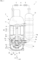
- Fig. 1 is a schematic configuration view of a refrigeration cycle device including a cross-sectional view of a rotary compressor 2 of the present embodiment.
- a refrigeration cycle device 1 includes the rotary compressor 2, a radiator (for example, a condenser) 3 connected to the rotary compressor 2, an expansion device (for example, an expansion valve) 4 connected to the radiator 3, and a heat absorber (for example, a vaporizer) 5 connected to the expansion device 4.
- the refrigeration cycle device 1 contains a refrigerant such as carbon dioxide (CO 2 ). The refrigerant circulates in the refrigeration cycle device 1 while changing its phase.
- CO 2 carbon dioxide
- the rotary compressor 2 is a so-called rotary type compressor.
- the rotary compressor 2 for example, compresses a low-pressure gaseous refrigerant (fluid) taken into the inside into a high-temperature and high-pressure gaseous refrigerant. Further, a specific configuration of the rotary compressor 2 will be described later.
- the radiator 3 radiates heat from the high-temperature and high-pressure gaseous refrigerant discharged from the rotary compressor 2.
- the expansion device 4 reduces a pressure of the high-pressure refrigerant sent from the radiator 3 to convert the high-pressure refrigerant into a low-temperature and low-pressure liquid refrigerant.
- the heat absorber 5 vaporizes the low-temperature and low-pressure liquid refrigerant sent from the expansion device 4 to convert the low-temperature and low-pressure liquid refrigerant into a low-pressure gaseous refrigerant.
- vaporization of the low-pressure liquid refrigerant removes vaporization heat from the surroundings, and thus the surroundings are cooled.
- the low-pressure gaseous refrigerant that has passed through the heat absorber 5 is taken into the rotary compressor 2 described above.
- a refrigerant serving as a working fluid circulates while changing its phase between a gaseous refrigerant and a liquid refrigerant, and heating, cooling, or the like is performed by utilizing such heat radiation and heat absorption.
- the rotary compressor 2 of the present embodiment includes a compressor main body 11 and an accumulator 12.
- the accumulator 12 is a so-called gas-liquid separator.
- the accumulator 12 is provided between the heat absorber 5 and the compressor main body 11 described above.
- the accumulator 12 is connected to the compressor main body 11 through a suction pipe 21.
- the accumulator 12 supplies a gaseous refrigerant vaporized by the heat absorber 5 to the compressor main body 11 through the suction pipe 21.
- the compressor main body 11 includes the shaft 31, the electric motor unit 32 that rotates the shaft 31, the compression mechanism unit 33 that compresses the gaseous refrigerant by rotation of the shaft 31, and a cylindrical airtight container 34 accommodating the shaft 31, the electric motor unit 32, and the compression mechanism unit 33.
- the shaft 31 and the airtight container 34 are disposed coaxially with respect to an axial center (axis) O of the shaft 31. Further, the axial center O of the shaft 31 means a center (rotation center) of the shaft 31.
- the electric motor unit 32 is disposed on the +Z side (upper side in Fig. 1 ) along the axial center O in the airtight container 34.
- the compression mechanism unit 33 is disposed on the -Z side (lower side in Fig. 1 ) along the axial center O in the airtight container 34.
- the shaft 31 penetrates the electric motor unit 32 and extends inside the compression mechanism unit 33 in the axial direction Z.
- the electric motor unit 32 is a so-called inner rotor type DC brushless motor.
- the electric motor unit 32 includes a stator 36 and a rotor 37.
- the stator 36 is formed in a cylindrical shape and is fixed to an inner wall surface of the airtight container 34 by shrink-fitting or the like.
- the rotor 37 is disposed on an inner side of the stator 36.
- the rotor 37 is connected to an upper portion of the shaft 31.
- the rotor 37 rotationally drives the shaft 31 when a current is supplied to a coil provided in the stator 36.
- the compression mechanism unit 33 is a multi-cylinder compression mechanism unit having a plurality of cylinder chambers.
- the compression mechanism unit 33 of the embodiment may be a two-cylinder compression mechanism unit having two cylinder chambers 51a and 52a.
- the compression mechanism unit 33 includes a plurality of cylinders 51 and 52, a partition plate 53, a main bearing (first bearing) 54, a sub bearing (second bearing) 55, a plurality of rollers 56 and 57, a main muffler member 91, and a sub muffler member 92.
- the plurality of cylinders include a first cylinder 51 and a second cylinder 52.
- the first cylinder 51 and the second cylinder 52 are disposed to be aligned in the axial direction Z.
- the first cylinder 51 and the second cylinder 52 are formed in a cylindrical shape that opens in the axial direction Z.
- the first cylinder 51 and the second cylinder 52 are disposed coaxially with the shaft 31 on an outer side of the shaft in the radial direction R.
- an internal space serving as a first cylinder chamber 51a is formed in the first cylinder 51.
- An inner circumferential surface of the first cylinder 51 forms an outer circumferential surface of the ring-shaped first cylinder chamber 51a.
- An internal space serving as a second cylinder chamber 52a is formed in the second cylinder 52.
- An inner circumferential surface of the second cylinder 52 forms an outer circumferential surface of the ring-shaped second cylinder chamber 52a.
- the partition plate 53 side of the first cylinder 51 and the second cylinder 52 in the axial direction Z may be referred to as an "inner side.”
- the main bearing 54 side of the first cylinder 51 and the sub bearing 55 side of the second cylinder 52 in the axial direction Z may be referred to as an "outer side.”
- the partition plate 53 is disposed between the first cylinder 51 and the second cylinder 52 in the axial direction Z and is sandwiched between the first cylinder 51 and the second cylinder 52.
- the partition plate 53 faces the internal space of the first cylinder chamber 51a in the axial direction Z to close the first cylinder chamber 51a.
- the partition plate 53 faces the internal space of the second cylinder chamber 52a to close the second cylinder chamber 52a.
- a shaft hole 53h through which the shaft 31 passes in the axial direction Z is provided in the partition plate 53. The shaft 31 described above penetrates the first cylinder 51, the second cylinder 52, and the partition plate 53.
- a first suction hole 76 extending in the radial direction R is formed in the first cylinder 51.
- An inner end portion of the first suction hole 76 in the radial direction R opens to the first cylinder chamber 51a.
- An outer end portion of the first suction hole 76 in the radial direction R is connected to the suction pipe 21 extending from the accumulator 12.
- the first cylinder chamber 51a can suction the gaseous refrigerant from the accumulator 12.
- a second suction hole 79 extending in the axial direction Z is formed in the first cylinder 51, the partition plate 53, and the second cylinder 52.
- An upper end portion of the second suction hole 79 in the axial direction Z opens to the first suction hole 76. That is, the second suction hole 79 is formed to be branched from the first suction hole 76. A lower end portion of the second suction hole 79 in the axial direction Z opens to the second cylinder chamber 52a. Thereby, the second cylinder chamber 52a can suction the gaseous refrigerant from the accumulator 12.
- the main bearing 54 is positioned on a side opposite to the partition plate 53 with the first cylinder 51 sandwiched therebetween.
- the main bearing 54 rotatably supports the shaft 31.
- the main bearing 54 includes a first flange part 54f formed at an end portion on the first cylinder 51 side.
- the first flange part 54f has a first surface 54s that closes the first cylinder chamber 51a.
- the sub bearing 55 is positioned on a side opposite to the partition plate 53 with the second cylinder 52 sandwiched therebetween.
- the sub bearing 55 rotatably supports the shaft 31.
- the sub bearing 55 includes a second flange part 55f formed at an end portion on the second cylinder 52 side.
- the second flange part 55f has a second surface 55s that closes the second cylinder chamber 52a.
- a first eccentric part 41 and a second eccentric part 42 are provided to be aligned in the axial direction Z on the shaft 31 described above.
- the first eccentric part 41 is provided at a position corresponding to the first cylinder chamber 51a in the axial direction Z and is disposed inside the first cylinder chamber 51a.
- the second eccentric part 42 is provided at a position corresponding to the second cylinder chamber 52a in the axial direction Z and is disposed inside the second cylinder chamber 52a.
- the first eccentric part 41 and the second eccentric part 42 are each formed in a columnar shape in the axial direction Z and are eccentric with respect to the axial center O by the same amount in the radial direction R.
- the first eccentric part 41 and the second eccentric part 42 may be formed, for example, to have the same shape and the same size in a plan view from the axial direction Z and may be disposed, for example, with a phase difference of 180° in the circumferential direction ⁇ .
- the plurality of rollers include a first roller 56 and a second roller 57.
- the first roller 56 and the second roller 57 are each formed in a cylindrical shape in the axial direction Z.
- the first roller 56 is fitted along an outer circumferential surface of the first eccentric part 41 and is disposed in the first cylinder chamber 51a.
- the second roller 57 is fitted along an outer circumferential surface of the second eccentric part 42 and is disposed in the second cylinder chamber 52a. Gaps for allowing relative rotation of the rollers 56 and 57 with respect to the eccentric parts 41 and 42 are respectively provided between inner circumferential surfaces of the rollers 56 and 57 and the eccentric parts 41 and 42.
- the first roller 56 and the second roller 57 eccentrically rotate inside the cylinder chambers 51a and 52a in accordance with rotation of the shaft 31 while outer circumferential surfaces of the rollers 56 and 57 are in sliding contact with inner circumferential surfaces of the cylinders 51 and 52.
- An internal configuration of the first cylinder 51 and an internal configuration of the second cylinder 52 are substantially the same as each other except for portions that differ according to phase differences between the eccentric parts 41 and 42 and between the rollers 56 and 57. Therefore, here, the internal configuration of the first cylinder 51 will be described as a representative. Then, constituents of the second cylinder 52 having the same functions as those in the first cylinder 51 will be denoted by the same reference signs and description thereof will be omitted.
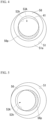
- Fig. 3 is a cross-sectional view of the compression mechanism unit 33 along line F-F of Fig. 2 .
- a vane groove 71 extending outward in the radial direction R is provided on the inner circumferential surface of the first cylinder 51.
- a vane 72 that is slidably movable in the radial direction R is inserted into the vane groove 71.
- the vane 72 is biased inward in the radial direction R by a biasing means (not illustrated), and a distal end thereof is brought into contact with the outer circumferential surface of the first roller 56 in the first cylinder chamber 51a.
- the vane 72 partitions the inside of the first cylinder chamber 51a into a suction chamber 74 and a compression chamber 75.
- the vane 72 moves back and forth in the first cylinder chamber 51a as the first roller 56 rotates eccentrically. Thereby, a suction operation of suctioning the gaseous refrigerant into the suction chamber 74 and a compression operation of compressing the gaseous refrigerant in the compression chamber 75 are performed.
- first suction hole 76 and a discharge groove 77 are provided in the first cylinder 51.
- the inner end portion of the first suction hole 76 in the radial direction R opens to the suction chamber 74 of the first cylinder chamber 51a.
- the discharge groove 77 is provided in the compression chamber 75.
- the discharge groove 77 is provided on the inner circumferential surface of the first cylinder 51 in the axial direction Z and communicates with a main bearing discharge hole to be described later.
- the discharge groove 77 guides the gaseous refrigerant compressed in the compression chamber 75 to the main bearing discharge hole.
- a discharge groove 77 provided in the second cylinder 52 communicates with a sub bearing discharge hole to be described later.
- the discharge groove 77 of the second cylinder 52 guides the gaseous refrigerant compressed in a compression chamber 75 to the sub bearing discharge hole.
- the main muffler member 91 forms a main muffler chamber 91a between itself and the main bearing 54.
- the gaseous refrigerant compressed in the compression chamber 75 of the first cylinder chamber 51a is discharged to the main muffler chamber 91a from the main bearing discharge hole (not illustrated) formed in the first flange part 54f.
- the gaseous refrigerant discharged into the main muffler chamber 91a is discharged into the airtight container 34 from a main muffler chamber discharge port 91e.
- the sub muffler member 92 forms a sub muffler chamber 92a between itself and the sub bearing 55.
- the gaseous refrigerant compressed in the compression chamber 75 of the second cylinder 52 is discharged to the sub muffler chamber 92a from the sub bearing discharge hole (not illustrated) formed in the second flange part 55f.
- the sub muffler chamber 92a communicates with the main muffler chamber 91a through a through hole (not illustrated) formed in the second cylinder 52, the partition plate 53, and the first cylinder 51. Therefore, the gaseous refrigerant discharged to the sub muffler chamber 92a moves to the main muffler chamber 91a and is discharged from the main muffler chamber discharge port 91e into the airtight container 34.
- the airtight container 34 includes a discharge pipe 35 on the +Z side of the rotor 37 of the electric motor unit 32.
- the discharge pipe 35 discharges the gaseous refrigerant discharged into the airtight container 34 to constituent units of the refrigeration cycle device outside the airtight container 34 such as the radiator 3.
- the first flange part 54f of the main bearing 54 described above has a first groove part 61.
- the first groove part 61 is formed on a surface of the first flange part 54f on the first cylinder 51 side.
- the first groove part 61 is formed in a ring shape when viewed from the axial direction Z.
- the first groove part 61 is disposed coaxially with the shaft 31 on an outer side of the shaft 31 in the radial direction R. Thereby, a first collar 66 that supports the shaft 31 is formed between the shaft 31 and the first groove part 61.
- the second flange part 55f of the sub bearing 55 has a second groove part 62.
- a second collar 67 that supports the shaft 31 is formed between the shaft 31 and the second groove part 62.
- the shaft 31 is likely to be bent between the main bearing 54 and the sub bearing 55. Even when the shaft 31 rotates while being bent, the first collar 66 and the second collar 67 support the shaft 31 while bending together with the shaft 31. Thereby, wear of the main bearing 54 and the sub bearing 55 due to rotation of the shaft 31 is suppressed.
- a thickness Tc of the partition plate 53 in the axial direction Z is smaller than a thickness Te1 of the first flange part 54f in the axial direction Z and a thickness Te2 of the second flange part 55f in the axial direction Z. Thereby, the distance between the main bearing 54 and the sub bearing 55 decreases. Accordingly, bending of the shaft 31 is suppressed.
- a lubricating oil is contained in the airtight container 34.
- a polyalkylene glycol (PAG) oil is contained as the lubricating oil (refrigerating machine oil).
- a PAG oil has a smaller decrease in viscosity when a refrigerant is dissolved compared to other lubricating oils such as a polyol ester (POE) oil and a polyvinyl ether (PVE) oil. Particularly, even when a carbon dioxide refrigerant is compressed to a high temperature, since the PAG oil has a small decrease in viscosity, a satisfactory lubrication state is maintained.
- the oil supply passage 80 includes a main passage 81 provided in the shaft 31, a sub-passage 82 and a communication passage 84 provided in the first eccentric part 41, and an end portion passage 85 provided in the +Z direction of the first eccentric part 41.
- a sub-passage and a communication passage are also provided in the second eccentric part 42.
- an end portion passage is also provided in the -Z direction of the second eccentric part 42.
- the sub-passage 82, the communication passage 84, and the end portion passage 85 provided in the first eccentric part 41 will be described as representatives.
- the main passage 81 is provided coaxially with the axial center O and is formed inside the shaft 31.
- the main passage 81 extends inside the shaft 31 in the axial direction Z.
- the main passage 81 opens inside the airtight container 34 at the end portion of the shaft 31 supported by the sub bearing 45.
- a part of the compression mechanism unit 33 is immersed in the lubricating oil contained in the airtight container 34.
- the lubricating oil flows into the main passage 81.
- a pumping means such as a torsion plate for pumping up the lubricating oil into the main passage 81 in accordance with rotation of the shaft 31 is provided inside the main passage 81.
- the sub-passage 82 is a groove provided on the outer circumferential surface of the first eccentric part 41.
- the sub-passage 82 is formed between the outer circumferential surface of the first eccentric part 41 and the inner circumferential surface of the first roller 56.
- the sub-passage 82 extends throughout the first eccentric part 41 in the axial direction Z.
- the communication passage 84 is provided inside the first eccentric part 41 in the radial direction R.
- the communication passage 84 is provided between the main passage 81 and the sub-passage 82 to connect the main passage 81 and the sub-passage 82.
- the lubricating oil pumped up into the main passage 81 flows into the sub-passage 82 through the communication passage 84 due to a centrifugal force according to rotation of the shaft 31. Further, the lubricating oil is supplied from the sub-passage 82 to various sliding portions of the compression mechanism unit 33.
- An inner end portion of the end portion passage 85 in the radial direction R opens to the main passage 81.
- An outer end portion of the end portion passage 85 in the radial direction R opens to the outer circumferential surface of the shaft 31.
- the lubricating oil pumped up into the main passage 81 is supplied to the outer circumferential surface of the shaft 31 through the end portion passage 85 by the centrifugal force according to the rotation of the shaft 31. Further, the lubricating oil is supplied from the outer circumferential surface of the shaft 31 to various sliding portions of the compression mechanism unit 33.
- the gaseous refrigerant compressed by the compression mechanism unit 33 is discharged into the airtight container 34.
- the gaseous refrigerant and lubricating oil inside the airtight container 34 are in a high-pressure state.
- a portion to which the lubricating oil is supplied through the oil supply passage 80 is also in a high-pressure state.
- the lubricating oil is supplied to a central portion region 53A, which is an inner region of the shaft hole 53h of the partition plate 53, via the sub-passage 82 of the oil supply passage 80.
- the lubricating oil is supplied to a first end portion region 61A, which is an inner region of an outer circumference of the first groove part 61 of the first flange part 54f, via the sub-passage 82 and the end portion passage 85 of the oil supply passage 80. Further, a distal end of the first collar 66 in the -Z direction is disposed in the +Z direction with respect to a surface of the first flange part 54f on the first cylinder 51 side. Therefore, the first end portion region 61A is a region from the outer circumference of the shaft 31 to the outer circumference of the first groove part 61 in the radial direction R.
- the lubricating oil is also supplied to a second end portion region 62A which is an inner region of an outer circumference of the second groove part 62 of the second flange part 55f. Accordingly, the central portion region 53A, the first end portion region 61A, and the second end portion region 62A are all in a high-pressure state.
- Fig. 4 is a first explanatory view of a pressure receiving portion of the first roller.
- Fig. 5 is a second explanatory view
- Fig. 6 is a third explanatory view
- Fig. 7 is a fourth explanatory view.
- Figs, 4 to 7 are cross-sectional views of a main part along line F-F of Fig. 2 .
- a part of the outer circumference of the central portion region 53A is disposed on an outer side of the inner circumference of the first roller 56 (outer circumference of the first eccentric part 41).
- a part of the outer circumference of the central portion region 53A is disposed between the inner circumference and the outer circumference of the first roller 56. That is, a part of the inner end surface of the first roller 56 becomes an exposed region 56p exposed to the central portion region 53A.
- Figs. 5 to 7 each illustrate a state in which the first roller 56 is eccentrically rotated by 90 degrees from Fig. 4 . Due to the eccentric rotation of the first roller 56, each part of the inner end surface of the first roller 56 along the inner circumference can be an exposed region 56p.
- Fig. 8 is an explanatory view of pressure receiving areas of inner end surfaces of the first roller and the second roller. Due to the eccentric rotation of the first roller 56, a ring-shaped region of the inner end surface of the first roller 56 along the inner circumference is a portion that can be exposed to the central portion region 53A. This ring-shaped region is a high-pressure region c1 that receives a high pressure from the central portion region 53A. An area (inner pressure receiving area) of the high-pressure region c1 on the inner end surface of the first roller 56 is defined as Sc1.
- a ring-shaped region of the inner end surface of the second roller 57 along the inner circumference can be exposed to the central portion region 53A.
- This ring-shaped region is a high-pressure region c2 that receives a high pressure from the central portion region 53A.
- An area (inner pressure receiving area) of the high-pressure region c2 on the inner end surface of the second roller 57 is defined as Sc2.
- the internal configuration of the first cylinder 51 and the internal configuration of the second cylinder 52 are the same except that the eccentric parts 41 and 42 are disposed in different phases from each other in the circumferential direction ⁇ . Also, an outer diameter of the central portion region 53A (inner diameter of the shaft hole 53h) is constant in the axial direction Z. Therefore, the inner pressure receiving area Sc1 of the first roller 56 and the inner pressure receiving area Sc2 of the second roller 57 are equivalent.
- an outer circumference of the first end portion region 61A (outer circumference of the first groove part 61) is always disposed on an inner side of the outer circumference of the first roller 56.
- a part of the outer circumference of the first end portion region 61A is disposed on an outer side of the inner circumference of the first roller 56. Accordingly, a part of the outer circumference of the first end portion region 61A is disposed between the inner circumference and the outer circumference of the first roller 56. A part of an outer end surface of the first roller 56 is exposed to the first end portion region 61A.
- Fig. 9 is an explanatory view of outer pressure receiving areas of the first roller and the second roller.
- a ring-shaped region of the outer end surface of the first roller 56 along the inner circumference is a portion that can be exposed to the first end portion region 61A.
- This ring-shaped region is a high-pressure region e1 that receives a high pressure from the first end portion region 61A.
- An area of the high-pressure region e1 (outer pressure receiving area) on the outer end surface of the first roller 56 is defined as Se1.
- a ring-shaped region of the outer end surface of the second roller 57 along the inner circumference can be exposed to the second end portion region 62A.
- This ring-shaped region is a high-pressure region e2 that receives a high pressure from the second end portion region 62A.
- An area of the high-pressure region e2 (outer pressure receiving area) on the outer end surface of the second roller 57 is defined as Se2.
- An outer diameter of the first end portion region 61A (outer diameter of the first groove part 61) and an outer diameter of the second end portion region 62A (outer diameter of the second groove part 62) may be the same as or different from each other.
- the outer pressure receiving area Se1 of the first roller 56 and the outer pressure receiving area Se2 of the second roller 57 are the same.
- the outer pressure receiving area Se1 of the first roller 56 and the outer pressure receiving area Se2 of the second roller 57 are different.
- an outer diameter (inner diameter of the shaft hole 53h) Dc of the central portion region 53A is larger than an outer diameter (outer diameter of the first groove part 61) De1 of the first end portion region 61A. Therefore, the inner pressure receiving area Sc1 of the first roller 56 is larger than the outer pressure receiving area Se1 of the first roller 56. That is, 1 ⁇ Sc1/Se1 is established. Further, a pressure in the central portion region 53A is equivalent to a pressure in the first end portion region 61A. Accordingly, a force received by the inner end surface of the first roller 56 in the +Z direction is larger than a force received by the outer end surface thereof in the -Z direction. Thereby, the first roller 56 is pressed toward the first flange part 54f of the main bearing 54.
- the outer diameter (inner diameter of the shaft hole 53h) Dc of the central portion region 53A is larger than an outer diameter (outer diameter of the second groove part 62) De2 of the second end portion region 62A. Therefore, the inner pressure receiving area Sc2 of the second roller 57 is larger than the outer pressure receiving area Se2 of the second roller 57. That is, 1 ⁇ Sc2/Se2 is established. Further, a pressure in the central portion region 53A is equivalent to a pressure in the second end portion region 62A. Accordingly, a force received by the inner end surface of the second roller 57 in the -Z direction is larger than a force received by the outer end surface thereof in the +Z direction. Thereby, the second roller 57 is pressed toward the second flange part 55f of the sub bearing 55.
- the thickness Tc of the partition plate 53 in the axial direction Z is smaller than the thickness Te1 of the first flange part 54f in the axial direction Z and the thickness Te2 of the second flange part 55f in the axial direction Z.
- the partition plate 53 since the partition plate 53 is likely to be bent, frictional forces of the partition plate 53 against the first roller 56 and the second roller 57 may increase.
- the first roller 56 is pressed toward the first flange part 54f, and the second roller 57 is pressed toward the second flange part 55f. Thereby, friction of the first roller 56 and the second roller 57 with the partition plate 53 is suppressed.
- a solid lubricating film 59 is formed on the first surface 54s of the first flange part 54f that forms the outer end surface of the first cylinder chamber 51a.
- the solid lubricating film 59 may be formed only on the first surface 54s or may be formed on the entire surface of the main bearing 54.
- a manganese phosphate film or a molybdenum dioxide film is preferably formed. These solid lubricating films 59 have excellent wear resistance and contribute to reduction in initial friction with the first roller 56.
- a manganese phosphate film may be formed on a lower layer that is in contact with the first surface 54s, and a molybdenum dioxide film may be formed on an upper layer that is in contact with the first roller 56. Since a manganese phosphate film has excellent wear resistance, reliability of the compressor is improved. Since a molybdenum dioxide film has a large effect in reducing initial friction, initial characteristics of the compressor are improved.
- the solid lubricating film 59 is also formed on the second surface 55s of the second flange part 55f that forms the outer end surface of the second cylinder chamber 52a.
- the first roller 56 is pressed toward the first flange part 54f, and the second roller 57 is pressed toward the second flange part 55f. Accordingly, friction of the first roller 56 and the second roller 57 with the partition plate 53 is suppressed. Therefore, the solid lubricating film 59 may be formed only on the first flange part 54f and the second flange part 55f. The solid lubricating film 59 is not formed on the partition plate 53 and the rollers 56 and 57. Accordingly, costs of the rotary compressor 2 are reduced.
- Fig. 10 is a graph showing a transition of an amount of wear on the first surface of the first flange part.
- an amount of wear is denoted by two types of marks according to a magnitude of a ratio of the inner pressure receiving area Sc1 to the outer pressure receiving area Se1 of the first roller 56.
- An amount of wear when 1 ⁇ Sc1/Se1 ⁇ 1.6 is denoted by a mark of ⁇ .
- An amount of wear when 1.6 ⁇ Sc1/Se1 is denoted by a mark of ⁇ .
- an amount of wear of a manganese phosphate film formed on the first surface 54s of the first flange part 54f is denoted.
- the first roller 56 is strongly pressed toward the first surface 54s.
- the amount of wear continues to increase even when the operating time exceeds t1. That is, the sliding surface has not been made smooth in the initial stage of the operation of the compressor, and the effect of initial adaptability cannot be obtained.
- the refrigerant of the refrigeration cycle device 1 is carbon dioxide
- the refrigerant is compressed to a high pressure
- an internal pressure of the airtight container 34 increases.
- the first roller 56 is strongly pressed toward the first surface 54s, the effect of initial adaptability cannot be easily obtained.
- a ratio of the inner pressure receiving area Sc1 to the outer pressure receiving area Se1 of the first roller 56 satisfy 1 ⁇ Sc1/Se1 ⁇ 1.6.
- a ratio of the inner pressure receiving area Sc2 to the outer pressure receiving area Se2 of the second roller 57 satisfy 1 ⁇ Sc2/Se2 ⁇ 1.6.
- the thickness of the partition plate 53 in the axial direction Z is smaller than the thickness of the first flange part 54f in the axial direction Z and the thickness of the second flange part 55f in the axial direction Z.
- the solid lubricating film 59 is formed on the first surface 54s of the first flange part 54f and the second surface 55s of the second flange part 55f.
- the solid lubricating film 59 is preferably a manganese phosphate film or a molybdenum dioxide film.
- the solid lubricating film 59 preferably includes a manganese phosphate film on the lower layer and a molybdenum dioxide film on the upper layer.
- the gas to be compressed in the rotary compressor 2 is carbon dioxide gas
- the lubricating oil is a polyalkylene glycol oil.
- the gas to be compressed is carbon dioxide, it is compressed to a high pressure. Even in this case, since Sc1/Se1 ⁇ 1.6 and Sc2/Se2 ⁇ 1.6 are established, an amount of wear on the first surface 54s and the second surface 55s is suppressed. Also, a polyalkylene glycol oil has a smaller decrease in viscosity when the refrigerant is dissolved than other lubricating oils. Thereby, a satisfactory lubrication state is maintained even when the gas to be compressed is compressed to a high temperature. Accordingly, an amount of wear on the first surface 54s and the second surface 55s is suppressed.
- the refrigeration cycle device 1 of the embodiment includes the rotary compressor 2 described above, the radiator 3 connected to the rotary compressor 2, the expansion device 4 connected to the radiator 3, and the heat absorber 5 connected to the expansion device 4.
- 1 ⁇ Sc1/Se1 ⁇ 1.6 and 1 ⁇ Sc2/Se2 ⁇ 1.6 are established. Thereby, a decrease in compression performance of the rotary compressor 2 can be suppressed.
Landscapes
- Engineering & Computer Science (AREA)
- Mechanical Engineering (AREA)
- General Engineering & Computer Science (AREA)
- Applications Or Details Of Rotary Compressors (AREA)
Claims (5)
- Ein Rotationskompressor (2), der eine Kompressionsmechanismuseinheit (33) umfasst, die ein zu komprimierendes Gas und ein Schmieröl komprimiert, die in einem Behälter (34) untergebracht sind, wobei
die Kompressionsmechanismuseinheit (33) umfasst:eine Welle (31);einen ersten Zylinder (51), der eine erste Zylinderkammer (51a) bildet;einen zweiten Zylinder (52), der so angeordnet ist, dass er mit dem ersten Zylinder (51) in einer axialen Richtung (Z) der Welle ausgerichtet ist, und eine zweite Zylinderkammer (52a) bildet;eine Trennplatte (53), die zwischen dem ersten Zylinder (51) und dem zweiten Zylinder (52) angeordnet ist, mit einem Wellenloch (53h), durch das die Welle (31) geführt ist, und ausgebildet ist, die erste Zylinderkammer (51a) und die zweite Zylinderkammer (52a) zu verschließen;ein erstes Lager (54) angeordnet auf einer Seite gegenüber von der Trennplatte (53) mit dem ersten Zylinder (51) dazwischen angeordnet ist und konfiguriert zum Tragen der Welle (31);ein zweites Lager (55) angeordnet auf einer Seite gegenüber von der Trennplatte (53) mit dem zweiten Zylinder (52) dazwischen angeordnet ist und konfiguriert ist zum Tragen der Welle (31) ;ein erstes Flanschteil (54f), das auf der ersten Zylinderseite des ersten Lagers (54) ausgebildet ist und eine erste Fläche (54s) aufweist, welche die erste Zylinderkammer (51a) verschließt;ein zweites Flanschteil (55f), das auf der zweiten Zylinderseite des zweiten Lagers (55) ausgebildet ist und eine zweite Fläche (55s) aufweist, welche die zweite Zylinderkammer (52a) verschließt;ein erstes exzentrisches Teil (41), das auf der Welle (31) ausgebildet ist und an einer Position des ersten Zylinders (51) in der axialen Richtung (Z) angeordnet ist;ein zweites exzentrisches Teil (42), das auf der Welle (31) ausgebildet und an einer Position des zweiten Zylinders (52) in der axialen Richtung (Z) angeordnet ist;eine erste Rolle (56), die entlang einer äußeren Umfangsfläche des ersten exzentrischen Teils (41) angeordnet und konfiguriert ist, sich entlang der ersten Fläche (54s) des ersten Flanschteils (54f) in Übereinstimmung mit der Drehung der Welle (31) zu bewegen; undeine zweite Rolle (57), die entlang einer äußeren Umfangsfläche des zweiten exzentrischen Teils (42) angeordnet und konfiguriert ist, sich entlang der zweiten Fläche (55s) des zweiten Flanschteils (55f) in Übereinstimmung mit der Drehung der Welle (31) zu bewegen,eine Dicke der Trennplatte (53) in axialer Richtung kleiner ist als eine Dicke des ersten Flanschteils (54f) in axialer Richtung und eine Dicke des zweiten Flanschteils (55f) in axialer Richtung,das erste Lager (54) ein erstes Nutteil (61) umfasst, das ringförmig auf einer Oberfläche des ersten Flanschteils (54f) ausgebildet ist und koaxial zur Welle (31) angeordnet ist,wobei 1 < Sc1/Se1 ≤ 1,6 festgelegt ist, wobei Sc1 den Bereich einer Endfläche der ersten Rolle (56) auf der Trennplattenseite definiert, die dem Wellenloch (53h) entsprechend der Bewegung der ersten Rolle (56) ausgesetzt ist, und wobei Se1 den Bereich einer Endfläche der ersten Rolle (56) auf der ersten Flanschteilseite definiert, die einem inneren Bereich eines Außenumfangs des ersten Nutteils (61) entsprechend der Bewegung der ersten Rolle (56) ausgesetzt ist; und wobei 1 < Sc2/Se2 ≤ 1. 6 festgelegt ist, wobei Sc2 den Bereich einer Endfläche der zweiten Rolle (57) auf der Trennplattenseite definiert, die entsprechend der Bewegung der zweiten Rolle (57) dem Wellenloch (53h) ausgesetzt ist, und wobei Se2 den Bereich einer Endfläche der zweiten Rolle (57) definiert; und wobei ein fester Schmierfilm (59) auf der ersten Oberfläche (54s) des ersten Flanschteils (54f) und der zweiten Oberfläche (55s) des zweiten Flanschteils (55f) ausgebildet ist, und wobei der feste Schmierfilm (59) zumindest auf der ersten Rolle (56), der zweiten Rolle (57) und der Trennplatte (53) nicht ausgebildet ist. - Rotationskompressor (2) nach Anspruch 1, dadurch gekennzeichnet, dass der feste Schmierfilm (59) ein Manganphosphatfilm oder ein Molybdändioxidfilm ist.
- Rotationskompressor (2) nach Anspruch 1, dadurch gekennzeichnet, dass der feste Schmierfilm (59) einen Manganphosphatfilm einer unteren Schicht und einen Molybdändioxidfilm einer oberen Schicht umfasst.
- Rotationskompressor (2) nach einem der Ansprüche 1 bis 3, dadurch gekennzeichnet, dass das zu verdichtende Gas Kohlendioxid ist und das Schmieröl ein Polyalkylenglykol-Öl ist.
- Kühlkreislaufvorrichtung (1), umfassend:einen Rotationskompressor (2) gemäß einem der Ansprüche 1 bis 4;einen mit dem Rotationskompressor (2) verbundenen Kühler (3);eine mit dem Kühler (3) verbundene Expansionsvorrichtung (4); undeinen mit der Expansionsvorrichtung (4) verbundenen Wärmeabsorber (5).
Applications Claiming Priority (1)
| Application Number | Priority Date | Filing Date | Title |
|---|---|---|---|
| PCT/JP2018/045713 WO2020121443A1 (ja) | 2018-12-12 | 2018-12-12 | 回転式圧縮機および冷凍サイクル装置 |
Publications (4)
| Publication Number | Publication Date |
|---|---|
| EP3896285A1 EP3896285A1 (de) | 2021-10-20 |
| EP3896285A4 EP3896285A4 (de) | 2022-08-03 |
| EP3896285B1 true EP3896285B1 (de) | 2025-02-26 |
| EP3896285B8 EP3896285B8 (de) | 2025-04-09 |
Family
ID=71075301
Family Applications (1)
| Application Number | Title | Priority Date | Filing Date |
|---|---|---|---|
| EP18942836.0A Active EP3896285B8 (de) | 2018-12-12 | 2018-12-12 | Drehkompressor und kühlkreisvorrichtung |
Country Status (4)
| Country | Link |
|---|---|
| EP (1) | EP3896285B8 (de) |
| JP (1) | JP7186242B2 (de) |
| CN (1) | CN113167276B (de) |
| WO (1) | WO2020121443A1 (de) |
Family Cites Families (12)
| Publication number | Priority date | Publication date | Assignee | Title |
|---|---|---|---|---|
| JPH04143483A (ja) * | 1990-10-05 | 1992-05-18 | Daikin Ind Ltd | ローリングピストン型圧縮機 |
| US20070071628A1 (en) * | 2005-09-29 | 2007-03-29 | Tecumseh Products Company | Compressor |
| JP4953974B2 (ja) * | 2007-08-10 | 2012-06-13 | 三菱電機株式会社 | ロータリ圧縮機 |
| JP2013072362A (ja) * | 2011-09-28 | 2013-04-22 | Daikin Industries Ltd | 圧縮機 |
| JP6156697B2 (ja) * | 2011-10-18 | 2017-07-05 | パナソニックIpマネジメント株式会社 | 2つのシリンダを持ったロータリ圧縮機 |
| JP2014202200A (ja) | 2013-04-10 | 2014-10-27 | ダイキン工業株式会社 | ロータリ圧縮機 |
| JP5964394B2 (ja) * | 2014-11-19 | 2016-08-03 | ファナック株式会社 | 電動機の回転子、電動機、工作機械、および回転子の製造方法 |
| JP2017133474A (ja) * | 2016-01-29 | 2017-08-03 | ダイキン工業株式会社 | ロータリー圧縮機 |
| JP7002033B2 (ja) * | 2016-02-26 | 2022-01-20 | パナソニックIpマネジメント株式会社 | 2シリンダ型密閉圧縮機 |
| WO2018116912A1 (ja) * | 2016-12-19 | 2018-06-28 | 東芝キヤリア株式会社 | 回転式圧縮機および冷凍サイクル装置 |
| JP6568841B2 (ja) * | 2016-12-27 | 2019-08-28 | 日立ジョンソンコントロールズ空調株式会社 | 密閉形回転圧縮機及び冷凍空調装置 |
| JP6768553B2 (ja) * | 2017-02-21 | 2020-10-14 | 東芝キヤリア株式会社 | 回転式圧縮機及び冷凍サイクル装置 |
-
2018
- 2018-12-12 CN CN201880099766.6A patent/CN113167276B/zh active Active
- 2018-12-12 WO PCT/JP2018/045713 patent/WO2020121443A1/ja not_active Ceased
- 2018-12-12 JP JP2020559610A patent/JP7186242B2/ja active Active
- 2018-12-12 EP EP18942836.0A patent/EP3896285B8/de active Active
Also Published As
| Publication number | Publication date |
|---|---|
| WO2020121443A1 (ja) | 2020-06-18 |
| CN113167276B (zh) | 2023-04-14 |
| JP7186242B2 (ja) | 2022-12-08 |
| EP3896285A1 (de) | 2021-10-20 |
| JPWO2020121443A1 (ja) | 2021-09-30 |
| EP3896285B8 (de) | 2025-04-09 |
| CN113167276A (zh) | 2021-07-23 |
| EP3896285A4 (de) | 2022-08-03 |
Similar Documents
| Publication | Publication Date | Title |
|---|---|---|
| US10180271B2 (en) | Multiple cylinder rotary compressor and refrigeration cycle apparatus | |
| JP5366856B2 (ja) | ベーンロータリ型流体装置及び圧縮機 | |
| US11002276B2 (en) | Compressor having bushing | |
| US20040071570A1 (en) | Horizontal two stage rotary compressor | |
| CN108457858B (zh) | 旋转式压缩机以及制冷循环装置 | |
| US10968912B2 (en) | Scroll compressor | |
| JP2015113817A (ja) | スクロール型圧縮機 | |
| US11028848B2 (en) | Scroll compressor having a fitted bushing and weight arrangement | |
| US6752605B2 (en) | Horizontal two stage rotary compressor with a bearing-driven lubrication structure | |
| EP3922854A1 (de) | Rotationsverdichter, verfahren zur herstellung eines rotationsverdichters und kältekreislaufvorrichtung | |
| JP6419186B2 (ja) | 回転式圧縮機及び冷凍サイクル装置 | |
| EP3896285B1 (de) | Drehkompressor und kühlkreisvorrichtung | |
| JP6148993B2 (ja) | 回転式圧縮機及び冷凍サイクル装置 | |
| US12025130B2 (en) | Rotary compressor and refrigeration cycle apparatus | |
| JP6735662B2 (ja) | 回転式圧縮機および冷凍サイクル装置 | |
| JP2016160793A (ja) | 回転式圧縮機及び冷凍サイクル装置 | |
| JP2017141802A (ja) | 回転式圧縮機および冷凍サイクル装置 | |
| EP3557066B1 (de) | Drehkompressor und kühlkreisvorrichtung | |
| WO2019171540A1 (ja) | ロータリコンプレッサおよび冷凍サイクル装置 | |
| JP6441119B2 (ja) | 回転式圧縮機及び冷凍サイクル装置 | |
| JP2018131969A (ja) | 冷媒圧縮機における摺動部材、及び同部材を有する冷媒圧縮機 | |
| US12313308B2 (en) | Rotary compressor and refrigeration cycle device | |
| KR20210010808A (ko) | 스크롤 압축기 | |
| JP2015218638A (ja) | 回転式圧縮機及び冷凍サイクル装置 |
Legal Events
| Date | Code | Title | Description |
|---|---|---|---|
| STAA | Information on the status of an ep patent application or granted ep patent |
Free format text: STATUS: THE INTERNATIONAL PUBLICATION HAS BEEN MADE |
|
| PUAI | Public reference made under article 153(3) epc to a published international application that has entered the european phase |
Free format text: ORIGINAL CODE: 0009012 |
|
| STAA | Information on the status of an ep patent application or granted ep patent |
Free format text: STATUS: REQUEST FOR EXAMINATION WAS MADE |
|
| 17P | Request for examination filed |
Effective date: 20210608 |
|
| AK | Designated contracting states |
Kind code of ref document: A1 Designated state(s): AL AT BE BG CH CY CZ DE DK EE ES FI FR GB GR HR HU IE IS IT LI LT LU LV MC MK MT NL NO PL PT RO RS SE SI SK SM TR |
|
| DAV | Request for validation of the european patent (deleted) | ||
| DAX | Request for extension of the european patent (deleted) | ||
| A4 | Supplementary search report drawn up and despatched |
Effective date: 20220701 |
|
| RIC1 | Information provided on ipc code assigned before grant |
Ipc: F04C 29/00 20060101ALI20220627BHEP Ipc: F04C 18/356 20060101ALI20220627BHEP Ipc: F04C 23/00 20060101AFI20220627BHEP |
|
| REG | Reference to a national code |
Ref country code: DE Ref legal event code: R079 Free format text: PREVIOUS MAIN CLASS: F04C0023000000 Ipc: F04C0018356000 Ref document number: 602018079725 Country of ref document: DE |
|
| GRAP | Despatch of communication of intention to grant a patent |
Free format text: ORIGINAL CODE: EPIDOSNIGR1 |
|
| STAA | Information on the status of an ep patent application or granted ep patent |
Free format text: STATUS: GRANT OF PATENT IS INTENDED |
|
| RIC1 | Information provided on ipc code assigned before grant |
Ipc: F04C 29/02 20060101ALI20240913BHEP Ipc: F04C 23/00 20060101ALI20240913BHEP Ipc: F04C 18/356 20060101AFI20240913BHEP |
|
| INTG | Intention to grant announced |
Effective date: 20241010 |
|
| GRAS | Grant fee paid |
Free format text: ORIGINAL CODE: EPIDOSNIGR3 |
|
| GRAA | (expected) grant |
Free format text: ORIGINAL CODE: 0009210 |
|
| STAA | Information on the status of an ep patent application or granted ep patent |
Free format text: STATUS: THE PATENT HAS BEEN GRANTED |
|
| AK | Designated contracting states |
Kind code of ref document: B1 Designated state(s): AL AT BE BG CH CY CZ DE DK EE ES FI FR GB GR HR HU IE IS IT LI LT LU LV MC MK MT NL NO PL PT RO RS SE SI SK SM TR |
|
| REG | Reference to a national code |
Ref country code: GB Ref legal event code: FG4D |
|
| REG | Reference to a national code |
Ref country code: CH Ref legal event code: EP |
|
| REG | Reference to a national code |
Ref country code: DE Ref legal event code: R081 Ref document number: 602018079725 Country of ref document: DE Owner name: CARRIER JAPAN CORPORATION, JP Free format text: FORMER OWNER: TOSHIBA CARRIER CORPORATION, KAWASAKI-SHI, KANAGAWA, JP |
|
| REG | Reference to a national code |
Ref country code: CH Ref legal event code: PK Free format text: BERICHTIGUNG B8 |
|
| REG | Reference to a national code |
Ref country code: DE Ref legal event code: R096 Ref document number: 602018079725 Country of ref document: DE |
|
| REG | Reference to a national code |
Ref country code: IE Ref legal event code: FG4D |
|
| RAP4 | Party data changed (patent owner data changed or rights of a patent transferred) |
Owner name: CARRIER JAPAN CORPORATION |
|
| REG | Reference to a national code |
Ref country code: NL Ref legal event code: MP Effective date: 20250226 |
|
| PG25 | Lapsed in a contracting state [announced via postgrant information from national office to epo] |
Ref country code: RS Free format text: LAPSE BECAUSE OF FAILURE TO SUBMIT A TRANSLATION OF THE DESCRIPTION OR TO PAY THE FEE WITHIN THE PRESCRIBED TIME-LIMIT Effective date: 20250526 |
|
| PG25 | Lapsed in a contracting state [announced via postgrant information from national office to epo] |
Ref country code: FI Free format text: LAPSE BECAUSE OF FAILURE TO SUBMIT A TRANSLATION OF THE DESCRIPTION OR TO PAY THE FEE WITHIN THE PRESCRIBED TIME-LIMIT Effective date: 20250226 |
|
| PG25 | Lapsed in a contracting state [announced via postgrant information from national office to epo] |
Ref country code: PL Free format text: LAPSE BECAUSE OF FAILURE TO SUBMIT A TRANSLATION OF THE DESCRIPTION OR TO PAY THE FEE WITHIN THE PRESCRIBED TIME-LIMIT Effective date: 20250226 |
|
| PG25 | Lapsed in a contracting state [announced via postgrant information from national office to epo] |
Ref country code: ES Free format text: LAPSE BECAUSE OF FAILURE TO SUBMIT A TRANSLATION OF THE DESCRIPTION OR TO PAY THE FEE WITHIN THE PRESCRIBED TIME-LIMIT Effective date: 20250226 |
|
| REG | Reference to a national code |
Ref country code: LT Ref legal event code: MG9D |
|
| PG25 | Lapsed in a contracting state [announced via postgrant information from national office to epo] |
Ref country code: IS Free format text: LAPSE BECAUSE OF FAILURE TO SUBMIT A TRANSLATION OF THE DESCRIPTION OR TO PAY THE FEE WITHIN THE PRESCRIBED TIME-LIMIT Effective date: 20250626 Ref country code: NO Free format text: LAPSE BECAUSE OF FAILURE TO SUBMIT A TRANSLATION OF THE DESCRIPTION OR TO PAY THE FEE WITHIN THE PRESCRIBED TIME-LIMIT Effective date: 20250526 |
|
| PG25 | Lapsed in a contracting state [announced via postgrant information from national office to epo] |
Ref country code: NL Free format text: LAPSE BECAUSE OF FAILURE TO SUBMIT A TRANSLATION OF THE DESCRIPTION OR TO PAY THE FEE WITHIN THE PRESCRIBED TIME-LIMIT Effective date: 20250226 |
|
| PG25 | Lapsed in a contracting state [announced via postgrant information from national office to epo] |
Ref country code: HR Free format text: LAPSE BECAUSE OF FAILURE TO SUBMIT A TRANSLATION OF THE DESCRIPTION OR TO PAY THE FEE WITHIN THE PRESCRIBED TIME-LIMIT Effective date: 20250226 |
|
| PG25 | Lapsed in a contracting state [announced via postgrant information from national office to epo] |
Ref country code: PT Free format text: LAPSE BECAUSE OF FAILURE TO SUBMIT A TRANSLATION OF THE DESCRIPTION OR TO PAY THE FEE WITHIN THE PRESCRIBED TIME-LIMIT Effective date: 20250626 Ref country code: LV Free format text: LAPSE BECAUSE OF FAILURE TO SUBMIT A TRANSLATION OF THE DESCRIPTION OR TO PAY THE FEE WITHIN THE PRESCRIBED TIME-LIMIT Effective date: 20250226 |
|
| PG25 | Lapsed in a contracting state [announced via postgrant information from national office to epo] |
Ref country code: BG Free format text: LAPSE BECAUSE OF FAILURE TO SUBMIT A TRANSLATION OF THE DESCRIPTION OR TO PAY THE FEE WITHIN THE PRESCRIBED TIME-LIMIT Effective date: 20250226 Ref country code: GR Free format text: LAPSE BECAUSE OF FAILURE TO SUBMIT A TRANSLATION OF THE DESCRIPTION OR TO PAY THE FEE WITHIN THE PRESCRIBED TIME-LIMIT Effective date: 20250527 |
|
| REG | Reference to a national code |
Ref country code: AT Ref legal event code: MK05 Ref document number: 1770860 Country of ref document: AT Kind code of ref document: T Effective date: 20250226 |
|
| PG25 | Lapsed in a contracting state [announced via postgrant information from national office to epo] |
Ref country code: SE Free format text: LAPSE BECAUSE OF FAILURE TO SUBMIT A TRANSLATION OF THE DESCRIPTION OR TO PAY THE FEE WITHIN THE PRESCRIBED TIME-LIMIT Effective date: 20250226 |
|
| PG25 | Lapsed in a contracting state [announced via postgrant information from national office to epo] |
Ref country code: SM Free format text: LAPSE BECAUSE OF FAILURE TO SUBMIT A TRANSLATION OF THE DESCRIPTION OR TO PAY THE FEE WITHIN THE PRESCRIBED TIME-LIMIT Effective date: 20250226 |
|
| PG25 | Lapsed in a contracting state [announced via postgrant information from national office to epo] |
Ref country code: DK Free format text: LAPSE BECAUSE OF FAILURE TO SUBMIT A TRANSLATION OF THE DESCRIPTION OR TO PAY THE FEE WITHIN THE PRESCRIBED TIME-LIMIT Effective date: 20250226 |
|
| PG25 | Lapsed in a contracting state [announced via postgrant information from national office to epo] |
Ref country code: IT Free format text: LAPSE BECAUSE OF FAILURE TO SUBMIT A TRANSLATION OF THE DESCRIPTION OR TO PAY THE FEE WITHIN THE PRESCRIBED TIME-LIMIT Effective date: 20250226 |
|
| PG25 | Lapsed in a contracting state [announced via postgrant information from national office to epo] |
Ref country code: AT Free format text: LAPSE BECAUSE OF FAILURE TO SUBMIT A TRANSLATION OF THE DESCRIPTION OR TO PAY THE FEE WITHIN THE PRESCRIBED TIME-LIMIT Effective date: 20250226 |
|
| PG25 | Lapsed in a contracting state [announced via postgrant information from national office to epo] |
Ref country code: CZ Free format text: LAPSE BECAUSE OF FAILURE TO SUBMIT A TRANSLATION OF THE DESCRIPTION OR TO PAY THE FEE WITHIN THE PRESCRIBED TIME-LIMIT Effective date: 20250226 |
|
| PG25 | Lapsed in a contracting state [announced via postgrant information from national office to epo] |
Ref country code: RO Free format text: LAPSE BECAUSE OF FAILURE TO SUBMIT A TRANSLATION OF THE DESCRIPTION OR TO PAY THE FEE WITHIN THE PRESCRIBED TIME-LIMIT Effective date: 20250226 |
|
| PG25 | Lapsed in a contracting state [announced via postgrant information from national office to epo] |
Ref country code: SK Free format text: LAPSE BECAUSE OF FAILURE TO SUBMIT A TRANSLATION OF THE DESCRIPTION OR TO PAY THE FEE WITHIN THE PRESCRIBED TIME-LIMIT Effective date: 20250226 |
|
| REG | Reference to a national code |
Ref country code: DE Ref legal event code: R097 Ref document number: 602018079725 Country of ref document: DE |
|
| PLBE | No opposition filed within time limit |
Free format text: ORIGINAL CODE: 0009261 |
|
| STAA | Information on the status of an ep patent application or granted ep patent |
Free format text: STATUS: NO OPPOSITION FILED WITHIN TIME LIMIT |
|
| PGFP | Annual fee paid to national office [announced via postgrant information from national office to epo] |
Ref country code: DE Payment date: 20251126 Year of fee payment: 8 |
|
| PGFP | Annual fee paid to national office [announced via postgrant information from national office to epo] |
Ref country code: GB Payment date: 20251119 Year of fee payment: 8 |
|
| PGFP | Annual fee paid to national office [announced via postgrant information from national office to epo] |
Ref country code: FR Payment date: 20251120 Year of fee payment: 8 |
|
| 26N | No opposition filed |
Effective date: 20251127 |