EP3894794B1 - Dispositif d'excitation d'un résolveur et ensemble résolveur - Google Patents
Dispositif d'excitation d'un résolveur et ensemble résolveur Download PDFInfo
- Publication number
- EP3894794B1 EP3894794B1 EP19798630.0A EP19798630A EP3894794B1 EP 3894794 B1 EP3894794 B1 EP 3894794B1 EP 19798630 A EP19798630 A EP 19798630A EP 3894794 B1 EP3894794 B1 EP 3894794B1
- Authority
- EP
- European Patent Office
- Prior art keywords
- connection
- resolver
- node
- voltage
- output
- Prior art date
- Legal status (The legal status is an assumption and is not a legal conclusion. Google has not performed a legal analysis and makes no representation as to the accuracy of the status listed.)
- Active
Links
Images

Classifications
-
- H—ELECTRICITY
- H03—ELECTRONIC CIRCUITRY
- H03M—CODING; DECODING; CODE CONVERSION IN GENERAL
- H03M1/00—Analogue/digital conversion; Digital/analogue conversion
- H03M1/12—Analogue/digital converters
- H03M1/48—Servo-type converters
- H03M1/485—Servo-type converters for position encoding, e.g. using resolvers or synchros
-
- G—PHYSICS
- G01—MEASURING; TESTING
- G01D—MEASURING NOT SPECIALLY ADAPTED FOR A SPECIFIC VARIABLE; ARRANGEMENTS FOR MEASURING TWO OR MORE VARIABLES NOT COVERED IN A SINGLE OTHER SUBCLASS; TARIFF METERING APPARATUS; MEASURING OR TESTING NOT OTHERWISE PROVIDED FOR
- G01D5/00—Mechanical means for transferring the output of a sensing member; Means for converting the output of a sensing member to another variable where the form or nature of the sensing member does not constrain the means for converting; Transducers not specially adapted for a specific variable
- G01D5/12—Mechanical means for transferring the output of a sensing member; Means for converting the output of a sensing member to another variable where the form or nature of the sensing member does not constrain the means for converting; Transducers not specially adapted for a specific variable using electric or magnetic means
- G01D5/14—Mechanical means for transferring the output of a sensing member; Means for converting the output of a sensing member to another variable where the form or nature of the sensing member does not constrain the means for converting; Transducers not specially adapted for a specific variable using electric or magnetic means influencing the magnitude of a current or voltage
- G01D5/20—Mechanical means for transferring the output of a sensing member; Means for converting the output of a sensing member to another variable where the form or nature of the sensing member does not constrain the means for converting; Transducers not specially adapted for a specific variable using electric or magnetic means influencing the magnitude of a current or voltage by varying inductance, e.g. by a movable armature
- G01D5/204—Mechanical means for transferring the output of a sensing member; Means for converting the output of a sensing member to another variable where the form or nature of the sensing member does not constrain the means for converting; Transducers not specially adapted for a specific variable using electric or magnetic means influencing the magnitude of a current or voltage by varying inductance, e.g. by a movable armature by influencing the mutual induction between two or more coils
- G01D5/2086—Mechanical means for transferring the output of a sensing member; Means for converting the output of a sensing member to another variable where the form or nature of the sensing member does not constrain the means for converting; Transducers not specially adapted for a specific variable using electric or magnetic means influencing the magnitude of a current or voltage by varying inductance, e.g. by a movable armature by influencing the mutual induction between two or more coils by movement of two or more coils with respect to two or more other coils
-
- G—PHYSICS
- G01—MEASURING; TESTING
- G01D—MEASURING NOT SPECIALLY ADAPTED FOR A SPECIFIC VARIABLE; ARRANGEMENTS FOR MEASURING TWO OR MORE VARIABLES NOT COVERED IN A SINGLE OTHER SUBCLASS; TARIFF METERING APPARATUS; MEASURING OR TESTING NOT OTHERWISE PROVIDED FOR
- G01D3/00—Indicating or recording apparatus with provision for the special purposes referred to in the subgroups
- G01D3/08—Indicating or recording apparatus with provision for the special purposes referred to in the subgroups with provision for safeguarding the apparatus, e.g. against abnormal operation, against breakdown
-
- G—PHYSICS
- G01—MEASURING; TESTING
- G01D—MEASURING NOT SPECIALLY ADAPTED FOR A SPECIFIC VARIABLE; ARRANGEMENTS FOR MEASURING TWO OR MORE VARIABLES NOT COVERED IN A SINGLE OTHER SUBCLASS; TARIFF METERING APPARATUS; MEASURING OR TESTING NOT OTHERWISE PROVIDED FOR
- G01D5/00—Mechanical means for transferring the output of a sensing member; Means for converting the output of a sensing member to another variable where the form or nature of the sensing member does not constrain the means for converting; Transducers not specially adapted for a specific variable
- G01D5/12—Mechanical means for transferring the output of a sensing member; Means for converting the output of a sensing member to another variable where the form or nature of the sensing member does not constrain the means for converting; Transducers not specially adapted for a specific variable using electric or magnetic means
- G01D5/14—Mechanical means for transferring the output of a sensing member; Means for converting the output of a sensing member to another variable where the form or nature of the sensing member does not constrain the means for converting; Transducers not specially adapted for a specific variable using electric or magnetic means influencing the magnitude of a current or voltage
- G01D5/20—Mechanical means for transferring the output of a sensing member; Means for converting the output of a sensing member to another variable where the form or nature of the sensing member does not constrain the means for converting; Transducers not specially adapted for a specific variable using electric or magnetic means influencing the magnitude of a current or voltage by varying inductance, e.g. by a movable armature
- G01D5/204—Mechanical means for transferring the output of a sensing member; Means for converting the output of a sensing member to another variable where the form or nature of the sensing member does not constrain the means for converting; Transducers not specially adapted for a specific variable using electric or magnetic means influencing the magnitude of a current or voltage by varying inductance, e.g. by a movable armature by influencing the mutual induction between two or more coils
-
- G—PHYSICS
- G01—MEASURING; TESTING
- G01R—MEASURING ELECTRIC VARIABLES; MEASURING MAGNETIC VARIABLES
- G01R31/00—Arrangements for testing electric properties; Arrangements for locating electric faults; Arrangements for electrical testing characterised by what is being tested not provided for elsewhere
- G01R31/34—Testing dynamo-electric machines
- G01R31/346—Testing of armature or field windings
Definitions
- the present invention relates to a device for exciting a resolver, as well as a resolver arrangement with such a device.
- a device and a method for determining an angular position by means of a resolver is known, for example, from the publication DE 10 2009 005 494 A1
- an excitation winding of a resolver is excited with a reference signal and the resulting signals from two other windings of the resolver are sampled and evaluated using Fourier coefficients.
- An alternative device for exciting a resolver is known.
- An amplifier circuit with a switching bridge, a low-pass filter and an inductive load is known.
- the present invention discloses a device for exciting a resolver, as well as a resolver arrangement with the features of independent Patent claims. Further advantageous embodiments are the subject of the dependent patent claims.
- a resolver arrangement with a resolver and a device according to the invention for exciting the resolver comprises an excitation winding with a first excitation connection and a second excitation connection.
- the present invention is based on the knowledge that a conventional excitation of an excitation coil for a resolver generally requires a power amplification of an excitation signal.
- a current amplification with a push-pull output stage is preferably used in a conventional control.
- the transistors of such a push-pull output stage operate at least temporarily in a so-called linear mode and thus cause a high power loss.
- Such a push-pull output stage requires a relatively high input voltage compared to the output voltage.
- the input voltage must be at least twice as high as the desired signal amplitude at the output.
- the device comprises a second half-bridge.
- the second half-bridge comprises a third switching element arranged between the supply voltage and a second node, and a fourth switching element arranged between the second node and the reference potential.
- the second node is coupled to the second output terminal.
- the control device is designed to control the first switching element, the second switching element, the third switching element and the fourth switching element. Accordingly, a separate half-bridge is provided for both the first output terminal and the second output terminal.
- control device is implemented by means of a microcontroller or microprocessor. If necessary, suitable driver stages for the semiconductor switching elements are provided between the outputs of the microcontroller and the control terminals of the semiconductor switches.
- the first output terminal is designed to be coupled to a first excitation terminal of a resolver.
- the second output terminal is designed to be coupled to a second excitation terminal of a resolver.
- the device for exciting the resolver can be electrically coupled to the excitation coil of a resolver in order to excite the excitation coil of the resolver with a predetermined electrical voltage, in particular an electrical voltage with a predetermined amplitude and/or a predetermined frequency.
- the control device is designed to detect an electrical output voltage between the first output terminal and the second output terminal.
- the first, second, third and fourth switching elements of the first and second half-bridge can be controlled using the detected output voltage.
- the excitation voltage for the resolver can thus be precisely set between the first and second output terminal and thus at the excitation coil of a resolver.
- component tolerances and variations, for example due to thermal shifts, in the characteristic sizes of the components can be compensated in this way.
- the first low-pass filter comprises a first inductance and a first capacitor.
- the second low-pass filter comprises a second inductance and a second capacitor.
- the first inductance of the first low-pass filter is connected to the first node of the first half-bridge at a first connection. Furthermore, the first inductance is electrically coupled to the first output connection at a second connection.
- the first capacitor of the first low-pass filter is connected to the second connection of the first inductance at a first connection. Furthermore, the first capacitor is connected to the reference potential at a second connection.
- the second inductance of the second low-pass filter is connected to the second node of the second half-bridge at a first connection.
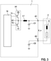
- the device for controlling a resolver comprises a first series capacitor and a second series capacitor.
- the first series capacitor is arranged in the current path between the first node and the first output connection.
- the second series capacitor is arranged in the current path between the second node and the second output connection.
- the first series capacitor and the second series capacitor are designed to form a series resonant circuit together with an excitation coil of a resolver that can be connected between the first output connection and the second output connection. If the capacitances of the two series capacitors are matched to the inductance of the excitation coil of the resolver and together form a series resonant circuit, this can achieve an increase in voltage. In this way, the excitation coil can be excited with a voltage that is higher than the electrical voltage provided between the first and second nodes of the half bridges. In particular, the voltage for exciting the excitation coil can be higher than the supply voltages of the device for exciting the resolver.
- the device for exciting a resolver comprises a first resistor and a second resistor.
- the first Resistor is arranged between the first output terminal and a third node.
- the second resistor is arranged between the second output terminal and the third node.
- the third node can be electrically coupled to a reference potential.
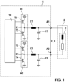
- Figure 1 shows a schematic representation of a basic circuit diagram as it is based on a device 1 for controlling a resolver 2 according to an embodiment.
- the device 1 for controlling the resolver 2 in this embodiment comprises a control device 10, a first half-bridge H1 and a second half-bridge H2.
- the first half-bridge H1 comprises a first switching element T1 and a second switching element T2.
- the first switching element T1 is connected to a supply voltage with one connection. Another connection of the first switching element T1 is connected to a first node K1.
- the control connection of the first switching element T1 is connected to the control device 10.
- the second switching element T2 is connected to the first node K1 with a first connection.
- a second connection of the control element T2 is connected to a reference potential.
- the switching elements T1 to T4 of the first and second half bridges H1 and H2 can be any switching elements.
- semiconductor switching elements for example MOSFET or similar, are possible.
- the present invention relates to the provision of an electrical voltage for exciting an excitation coil of a resolver.
- the electrical voltage for exciting the excitation coil of the resolver is generated by means of a pulse-width modulated control of at least one half-bridge.
- the switching elements of the half-bridges are fully switched through so that losses, such as those that occur in the linear operation of semiconductor switches, can be avoided. If necessary, the voltage provided by the half-bridge(s) can be additionally increased by means of suitable resonant circuits.
Landscapes
- Physics & Mathematics (AREA)
- General Physics & Mathematics (AREA)
- Engineering & Computer Science (AREA)
- Theoretical Computer Science (AREA)
- Transmission And Conversion Of Sensor Element Output (AREA)
Claims (12)
- Dispositif (1) permettant d'exciter un résolveur (2), comprenant :une première borne de sortie (A1) qui est conçue pour être couplée à une première borne d'excitation du résolveur (2),une deuxième borne de sortie (A2) qui est conçue pour être couplée à une deuxième borne d'excitation du résolveur (2),un premier demi-pont (H1) pourvu d'un premier élément de commutation (T1) qui est disposé entre une tension d'alimentation et un premier nœud (K1), et d'un deuxième élément de commutation (T2) qui est disposé entre le premier nœud (K1) et un potentiel de référence, le premier nœud (K1) étant couplé à la première borne de sortie (A1) ; etun dispositif de commande (10) qui est conçu pour piloter le premier élément de commutation (T1) et le deuxième élément de commutation (T2),caractérisé en ce quele dispositif de commande (10) est réalisé parun microcontrôleur ou un microprocesseur et est conçu pour fournir aux entrées de commande des éléments de commutation (T1 à T4) respectivement un signal de commande modulé en largeur d'impulsion, les éléments de commutation (T1, T2) individuels étant entièrement interconnectés dans le demi-pont.
- Dispositif (1) selon la revendication 1, comprenant un premier filtre passe-bas qui est disposé entre le premier nœud (K1) et la première borne de sortie (A1).
- Dispositif (1) selon la revendication 2, dans lequel le premier filtre passe-bas comprend une première inductance (L1) et un premier condensateur (C1), dans lequel la première inductance (L1) est reliée au niveau d'une première borne au premier nœud (K1) du premier demi-pont (H1), et est couplée électriquement au niveau d'une deuxième borne à la première borne de sortie (A1), et le premier condensateur (C1) est relié au niveau d'une première borne à la deuxième borne de la première inductance (L1), et est relié au niveau d'une deuxième borne au potentiel de référence.
- Dispositif (1) selon l'une quelconque des revendications 1 à 3, comprenant un deuxième demi-pont (H2) pourvu d'un troisième élément de commutation (T3) qui est disposé entre la tension d'alimentation et un deuxième nœud (K2), et d'un quatrième élément de commutation (T4) qui est disposé entre le deuxième nœud (K2) et le potentiel de référence, le deuxième nœud (K2) étant couplé à la deuxième borne de sortie (A2) ;
dans lequel le dispositif de commande (10) est conçu pour piloter le premier élément de commutation (T1), le deuxième élément de commutation (T2), le troisième élément de commutation (T3) et le quatrième élément de commutation (T4). - Dispositif (1) selon l'une quelconque des revendications 1 à 4, dans lequel le dispositif de commande (10) est conçu pour détecter une tension de sortie (U_e) électrique entre la première borne de sortie (A1) et la deuxième borne de sortie (A2), et pour piloter les éléments de commutation (T1 à T4) en utilisant la tension de sortie (U_e) détectée.
- Dispositif (1) selon l'une quelconque des revendications 1 à 5, comprenant un deuxième filtre passe-bas qui est disposé entre le deuxième nœud (K2) et la deuxième borne de sortie (A2).
- Dispositif (1) selon la revendication 6,
dans lequel le deuxième filtre passe-bas comprend une deuxième inductance (L2) et un deuxième condensateur (C2), dans lequel la deuxième inductance (L2) est reliée au niveau d'une première borne au deuxième nœud (K2) du deuxième demi-pont (H2), et est couplée électriquement au niveau d'une deuxième borne à la deuxième borne de sortie (A2), et le deuxième condensateur (C2) est relié au niveau d'une première borne à la deuxième borne de la deuxième inductance (L2) et est relié au niveau d'une deuxième borne au potentiel de référence. - Dispositif (1) selon l'une quelconque des revendications 4 à 7, comprenant un premier condensateur série (C3) qui est disposé entre le premier nœud (K1) et la première borne de sortie (A1) ; et
comprenant un deuxième condensateur série (C4) qui est disposé entre le deuxième nœud (K2) et la deuxième borne de sortie (A2). - Dispositif (1) selon la revendication 8, dans lequel le premier condensateur série (C3) et le deuxième condensateur série (C4) sont conçus pour former un circuit oscillant série avec une bobine d'excitation (E) d'un résolveur (2), pouvant être connectée entre la première borne de sortie (A1) et la deuxième borne de sortie (A2).
- Dispositif (1) selon l'une quelconque des revendications 4 à 9, comprenant une première résistance (R1) qui est disposée entre la première borne de sortie (A1) et un premier potentiel de tension, et
comprenant une deuxième résistance (R2) qui est disposée entre la deuxième borne de sortie (A2) et un quatrième potentiel de tension. - Dispositif selon la revendication 10, dans lequel le troisième potentiel de tension et le quatrième potentiel de tension sont identiques.
- Ensemble résolveur, comprenant :un résolveur (2) comprenant une bobine d'excitation (E) pourvue d'une première borne d'excitation et d'une deuxième borne d'excitation ; etun dispositif (1) permettant d'exciter le résolveur (2) selon l'une quelconque des revendications 1 à 11.
Applications Claiming Priority (2)
| Application Number | Priority Date | Filing Date | Title |
|---|---|---|---|
| DE102018221295.3A DE102018221295A1 (de) | 2018-12-10 | 2018-12-10 | Vorrichtung zur Anregung eines Resolvers und Resolveranordnung |
| PCT/EP2019/080377 WO2020120035A1 (fr) | 2018-12-10 | 2019-11-06 | Dispositif d'excitation d'un résolveur et arrangement résolveur |
Publications (2)
| Publication Number | Publication Date |
|---|---|
| EP3894794A1 EP3894794A1 (fr) | 2021-10-20 |
| EP3894794B1 true EP3894794B1 (fr) | 2025-01-08 |
Family
ID=68470527
Family Applications (1)
| Application Number | Title | Priority Date | Filing Date |
|---|---|---|---|
| EP19798630.0A Active EP3894794B1 (fr) | 2018-12-10 | 2019-11-06 | Dispositif d'excitation d'un résolveur et ensemble résolveur |
Country Status (5)
| Country | Link |
|---|---|
| US (1) | US11994413B2 (fr) |
| EP (1) | EP3894794B1 (fr) |
| CN (1) | CN113167600A (fr) |
| DE (1) | DE102018221295A1 (fr) |
| WO (1) | WO2020120035A1 (fr) |
Families Citing this family (3)
| Publication number | Priority date | Publication date | Assignee | Title |
|---|---|---|---|---|
| CN116191973A (zh) * | 2022-07-06 | 2023-05-30 | 方地应用技术(上海)有限公司 | 一种方波励磁的旋变角度检测系统 |
| WO2024210952A1 (fr) * | 2023-04-05 | 2024-10-10 | Microchip Technology Incorporated | Circuit d'excitation push-pull en pont en h pour résolveur |
| US12535539B2 (en) * | 2023-09-29 | 2026-01-27 | Texas Instruments Incorporated | Fault detection front end architecture in resolver |
Family Cites Families (15)
| Publication number | Priority date | Publication date | Assignee | Title |
|---|---|---|---|---|
| US4894621A (en) * | 1988-06-13 | 1990-01-16 | Westinghouse Electric Corp. | Circuit for five level waveform synthesis |
| JP4682813B2 (ja) * | 2005-11-11 | 2011-05-11 | パナソニック株式会社 | 電源装置 |
| DE102009005494A1 (de) | 2009-01-21 | 2010-07-22 | Kuka Roboter Gmbh | Verfahren und Vorrichtung zur Bestimmung einer Winkellage mittels eines Resolvers |
| JP5428688B2 (ja) * | 2009-09-14 | 2014-02-26 | 株式会社ジェイテクト | モータ制御装置及び電動パワーステアリング装置 |
| CN103998899B (zh) | 2012-02-24 | 2016-09-07 | 爱信艾达株式会社 | 旋转变压器励磁装置 |
| CN103759773B (zh) | 2014-02-18 | 2016-03-09 | 北京中锐智诚科技有限公司 | 励磁电压调整方法、控制电路及电磁流量计励磁电路 |
| US9778071B2 (en) * | 2014-06-12 | 2017-10-03 | Lear Corporation | Excitation signal generator for resolver |
| JP6109370B1 (ja) * | 2016-03-22 | 2017-04-05 | 三菱電機株式会社 | 回転角度検出装置 |
| JP2017175586A (ja) * | 2016-03-25 | 2017-09-28 | ヤマハ株式会社 | Btl出力の自励式d級増幅器 |
| WO2017190007A1 (fr) * | 2016-04-29 | 2017-11-02 | Massachusetts Institute Of Technology | Convertisseur à commutation douce, à transition résonante, à plage de fonctionnement large |
| CN107478279A (zh) * | 2016-06-08 | 2017-12-15 | 西尼尔(南京)过程控制有限公司 | 电磁流量计及其励磁电压调节方法 |
| DE102016220358A1 (de) * | 2016-10-18 | 2018-04-19 | Robert Bosch Gmbh | Gleichspannungswandler und Verfahren zur Ansteuerung eines Gleichspannungswandlers |
| JP6806532B2 (ja) | 2016-11-09 | 2021-01-06 | アズビル株式会社 | 電磁流量計の励磁回路、および電磁流量計 |
| CN107659224B (zh) | 2017-08-18 | 2020-03-06 | 天津大学 | 基于方波激励信号的旋转变压器轴角转换的装置及方法 |
| US11005356B2 (en) * | 2018-11-07 | 2021-05-11 | Rohm Co., Ltd. | Power supply control device and LLC resonant converter |
-
2018
- 2018-12-10 DE DE102018221295.3A patent/DE102018221295A1/de not_active Withdrawn
-
2019
- 2019-11-06 WO PCT/EP2019/080377 patent/WO2020120035A1/fr not_active Ceased
- 2019-11-06 US US17/312,915 patent/US11994413B2/en active Active
- 2019-11-06 CN CN201980081589.3A patent/CN113167600A/zh active Pending
- 2019-11-06 EP EP19798630.0A patent/EP3894794B1/fr active Active
Also Published As
| Publication number | Publication date |
|---|---|
| DE102018221295A1 (de) | 2020-06-10 |
| WO2020120035A1 (fr) | 2020-06-18 |
| CN113167600A (zh) | 2021-07-23 |
| US11994413B2 (en) | 2024-05-28 |
| EP3894794A1 (fr) | 2021-10-20 |
| US20220042827A1 (en) | 2022-02-10 |
Similar Documents
| Publication | Publication Date | Title |
|---|---|---|
| EP2349041B1 (fr) | Générateur chirurgical hf | |
| DE102008034109B4 (de) | Schaltung zur Nachbildung einer elektrischen Last | |
| DE10262286B4 (de) | Leistungsversorgungsvorrichtung zum Erzeugen von Hochfrequenzleistung für eine Plasmaerzeugungsvorrichtung | |
| DE69838991T2 (de) | Treiber für piezoelektrische motoren | |
| EP3840980B1 (fr) | Dispositif de charge avec tension centrale du circuit intermédiaire commandable et système d'entraînement avec tel dispositif de charge | |
| EP3894794B1 (fr) | Dispositif d'excitation d'un résolveur et ensemble résolveur | |
| WO2003077414A2 (fr) | Amplificateur de puissance | |
| EP1317673A1 (fr) | Circuit d'evaluation pour detecteur de courant, fonctionnant selon le principe de compensation et permettant notamment de mesurer des courants continus et des courants alternatifs, et procede d'exploitation d'un tel detecteur de courant | |
| DE4302056A1 (de) | Resonanter Wechselrichter | |
| WO2018210869A1 (fr) | Onduleur comprenant des condensateurs de circuit intermédiaire en cascade ainsi que des filtres en mode commun et des filtres en mode différentiel côté cc | |
| EP2036138B1 (fr) | Dispositif comprenant actionneur piézoélectrique | |
| EP3667917A1 (fr) | Circuit de commande pour un circuit oscillateur destiné au fonctionnement des oscillateurs à alimentation parallèle | |
| EP2979311B1 (fr) | Agencement de circuit et procédé d'excitation d'un transformateur piézoélectrique | |
| WO2020007812A1 (fr) | Procédé pour faire fonctionner un circuit destiné à produire un champ électromagnétique et circuit | |
| EP2945288A1 (fr) | Circuit et procédé de commande d'un élément commutateur de semi-conducteur | |
| DE19810321A1 (de) | Verfahren und Schaltungsanordnung zur Strom- und Ladungsregelung von kapazitiven Lasten und deren Verwendung | |
| DE4023253A1 (de) | Einrichtung zur speisung eines verbraucherzweipols mit einer weitgehend oberschwingungsfreien und dennoch rasch veraenderbaren gleichspannung oder einem weitgehend oberschwingungsfreien und dennoch rasch veraenderbaren gleichstrom | |
| EP3410589B1 (fr) | Inverseur, dispositif avec un tel inverseur, système et procédé de commande d'une source d'énergie contrôlable | |
| DE4322608C2 (de) | Einrichtung zur Leistungsmodulation bei einer Plasmaanregung, vorzugsweise beim Einsatz von Gaslasern | |
| DE102023200513A1 (de) | Filtervorrichtung und Verfahren zum Betreiben einer Filtervorrichtung für ein elektrisches Antriebssystem, elektrisches Antriebssystem | |
| DE102022210189A1 (de) | Gleichspannungswandler, Elektrofahrzeug und Verfahren zum Betreiben eines Gleichspannungswandlers | |
| WO2007082601A1 (fr) | Contrôleur à modulation d'impulsions en durée à auto-excitation destiné à un moteur à ultrasons monophase | |
| DE3836950A1 (de) | Schaltungsanordnung zur ansteuerung eines buerstenlosen gleichstrommotors | |
| DE102011089963A1 (de) | EMV-optimiertes Verfahren zum getakteten Betreiben einer PWM-Endstufe | |
| EP2375551B1 (fr) | Procédé de commutation, circuit de commutation et convertisseur d'énergie électrique |
Legal Events
| Date | Code | Title | Description |
|---|---|---|---|
| STAA | Information on the status of an ep patent application or granted ep patent |
Free format text: STATUS: UNKNOWN |
|
| STAA | Information on the status of an ep patent application or granted ep patent |
Free format text: STATUS: THE INTERNATIONAL PUBLICATION HAS BEEN MADE |
|
| PUAI | Public reference made under article 153(3) epc to a published international application that has entered the european phase |
Free format text: ORIGINAL CODE: 0009012 |
|
| STAA | Information on the status of an ep patent application or granted ep patent |
Free format text: STATUS: REQUEST FOR EXAMINATION WAS MADE |
|
| 17P | Request for examination filed |
Effective date: 20210712 |
|
| AK | Designated contracting states |
Kind code of ref document: A1 Designated state(s): AL AT BE BG CH CY CZ DE DK EE ES FI FR GB GR HR HU IE IS IT LI LT LU LV MC MK MT NL NO PL PT RO RS SE SI SK SM TR |
|
| DAV | Request for validation of the european patent (deleted) | ||
| DAX | Request for extension of the european patent (deleted) | ||
| STAA | Information on the status of an ep patent application or granted ep patent |
Free format text: STATUS: EXAMINATION IS IN PROGRESS |
|
| 17Q | First examination report despatched |
Effective date: 20221214 |
|
| GRAP | Despatch of communication of intention to grant a patent |
Free format text: ORIGINAL CODE: EPIDOSNIGR1 |
|
| STAA | Information on the status of an ep patent application or granted ep patent |
Free format text: STATUS: GRANT OF PATENT IS INTENDED |
|
| RIC1 | Information provided on ipc code assigned before grant |
Ipc: H03M 1/48 20060101ALI20240927BHEP Ipc: G01D 5/20 20060101AFI20240927BHEP |
|
| INTG | Intention to grant announced |
Effective date: 20241014 |
|
| GRAS | Grant fee paid |
Free format text: ORIGINAL CODE: EPIDOSNIGR3 |
|
| GRAA | (expected) grant |
Free format text: ORIGINAL CODE: 0009210 |
|
| STAA | Information on the status of an ep patent application or granted ep patent |
Free format text: STATUS: THE PATENT HAS BEEN GRANTED |
|
| AK | Designated contracting states |
Kind code of ref document: B1 Designated state(s): AL AT BE BG CH CY CZ DE DK EE ES FI FR GB GR HR HU IE IS IT LI LT LU LV MC MK MT NL NO PL PT RO RS SE SI SK SM TR |
|
| REG | Reference to a national code |
Ref country code: GB Ref legal event code: FG4D Free format text: NOT ENGLISH |
|
| REG | Reference to a national code |
Ref country code: CH Ref legal event code: EP |
|
| REG | Reference to a national code |
Ref country code: DE Ref legal event code: R096 Ref document number: 502019012784 Country of ref document: DE |
|
| REG | Reference to a national code |
Ref country code: IE Ref legal event code: FG4D Free format text: LANGUAGE OF EP DOCUMENT: GERMAN |
|
| REG | Reference to a national code |
Ref country code: LT Ref legal event code: MG9D |
|
| REG | Reference to a national code |
Ref country code: NL Ref legal event code: MP Effective date: 20250108 |
|
| PG25 | Lapsed in a contracting state [announced via postgrant information from national office to epo] |
Ref country code: NL Free format text: LAPSE BECAUSE OF FAILURE TO SUBMIT A TRANSLATION OF THE DESCRIPTION OR TO PAY THE FEE WITHIN THE PRESCRIBED TIME-LIMIT Effective date: 20250108 |
|
| PG25 | Lapsed in a contracting state [announced via postgrant information from national office to epo] |
Ref country code: RS Free format text: LAPSE BECAUSE OF FAILURE TO SUBMIT A TRANSLATION OF THE DESCRIPTION OR TO PAY THE FEE WITHIN THE PRESCRIBED TIME-LIMIT Effective date: 20250408 |
|
| PG25 | Lapsed in a contracting state [announced via postgrant information from national office to epo] |
Ref country code: FI Free format text: LAPSE BECAUSE OF FAILURE TO SUBMIT A TRANSLATION OF THE DESCRIPTION OR TO PAY THE FEE WITHIN THE PRESCRIBED TIME-LIMIT Effective date: 20250108 |
|
| PG25 | Lapsed in a contracting state [announced via postgrant information from national office to epo] |
Ref country code: PL Free format text: LAPSE BECAUSE OF FAILURE TO SUBMIT A TRANSLATION OF THE DESCRIPTION OR TO PAY THE FEE WITHIN THE PRESCRIBED TIME-LIMIT Effective date: 20250108 |
|
| PG25 | Lapsed in a contracting state [announced via postgrant information from national office to epo] |
Ref country code: ES Free format text: LAPSE BECAUSE OF FAILURE TO SUBMIT A TRANSLATION OF THE DESCRIPTION OR TO PAY THE FEE WITHIN THE PRESCRIBED TIME-LIMIT Effective date: 20250108 |
|
| PG25 | Lapsed in a contracting state [announced via postgrant information from national office to epo] |
Ref country code: IS Free format text: LAPSE BECAUSE OF FAILURE TO SUBMIT A TRANSLATION OF THE DESCRIPTION OR TO PAY THE FEE WITHIN THE PRESCRIBED TIME-LIMIT Effective date: 20250508 Ref country code: NO Free format text: LAPSE BECAUSE OF FAILURE TO SUBMIT A TRANSLATION OF THE DESCRIPTION OR TO PAY THE FEE WITHIN THE PRESCRIBED TIME-LIMIT Effective date: 20250408 |
|
| PG25 | Lapsed in a contracting state [announced via postgrant information from national office to epo] |
Ref country code: HR Free format text: LAPSE BECAUSE OF FAILURE TO SUBMIT A TRANSLATION OF THE DESCRIPTION OR TO PAY THE FEE WITHIN THE PRESCRIBED TIME-LIMIT Effective date: 20250108 |
|
| PG25 | Lapsed in a contracting state [announced via postgrant information from national office to epo] |
Ref country code: LV Free format text: LAPSE BECAUSE OF FAILURE TO SUBMIT A TRANSLATION OF THE DESCRIPTION OR TO PAY THE FEE WITHIN THE PRESCRIBED TIME-LIMIT Effective date: 20250108 Ref country code: PT Free format text: LAPSE BECAUSE OF FAILURE TO SUBMIT A TRANSLATION OF THE DESCRIPTION OR TO PAY THE FEE WITHIN THE PRESCRIBED TIME-LIMIT Effective date: 20250508 |
|
| PG25 | Lapsed in a contracting state [announced via postgrant information from national office to epo] |
Ref country code: BG Free format text: LAPSE BECAUSE OF FAILURE TO SUBMIT A TRANSLATION OF THE DESCRIPTION OR TO PAY THE FEE WITHIN THE PRESCRIBED TIME-LIMIT Effective date: 20250108 Ref country code: GR Free format text: LAPSE BECAUSE OF FAILURE TO SUBMIT A TRANSLATION OF THE DESCRIPTION OR TO PAY THE FEE WITHIN THE PRESCRIBED TIME-LIMIT Effective date: 20250409 |
|
| PG25 | Lapsed in a contracting state [announced via postgrant information from national office to epo] |
Ref country code: SE Free format text: LAPSE BECAUSE OF FAILURE TO SUBMIT A TRANSLATION OF THE DESCRIPTION OR TO PAY THE FEE WITHIN THE PRESCRIBED TIME-LIMIT Effective date: 20250108 |
|
| PG25 | Lapsed in a contracting state [announced via postgrant information from national office to epo] |
Ref country code: SM Free format text: LAPSE BECAUSE OF FAILURE TO SUBMIT A TRANSLATION OF THE DESCRIPTION OR TO PAY THE FEE WITHIN THE PRESCRIBED TIME-LIMIT Effective date: 20250108 |
|
| REG | Reference to a national code |
Ref country code: DE Ref legal event code: R097 Ref document number: 502019012784 Country of ref document: DE |
|
| PG25 | Lapsed in a contracting state [announced via postgrant information from national office to epo] |
Ref country code: DK Free format text: LAPSE BECAUSE OF FAILURE TO SUBMIT A TRANSLATION OF THE DESCRIPTION OR TO PAY THE FEE WITHIN THE PRESCRIBED TIME-LIMIT Effective date: 20250108 |
|
| PG25 | Lapsed in a contracting state [announced via postgrant information from national office to epo] |
Ref country code: EE Free format text: LAPSE BECAUSE OF FAILURE TO SUBMIT A TRANSLATION OF THE DESCRIPTION OR TO PAY THE FEE WITHIN THE PRESCRIBED TIME-LIMIT Effective date: 20250108 Ref country code: CZ Free format text: LAPSE BECAUSE OF FAILURE TO SUBMIT A TRANSLATION OF THE DESCRIPTION OR TO PAY THE FEE WITHIN THE PRESCRIBED TIME-LIMIT Effective date: 20250108 |
|
| PG25 | Lapsed in a contracting state [announced via postgrant information from national office to epo] |
Ref country code: RO Free format text: LAPSE BECAUSE OF FAILURE TO SUBMIT A TRANSLATION OF THE DESCRIPTION OR TO PAY THE FEE WITHIN THE PRESCRIBED TIME-LIMIT Effective date: 20250108 |
|
| PG25 | Lapsed in a contracting state [announced via postgrant information from national office to epo] |
Ref country code: SK Free format text: LAPSE BECAUSE OF FAILURE TO SUBMIT A TRANSLATION OF THE DESCRIPTION OR TO PAY THE FEE WITHIN THE PRESCRIBED TIME-LIMIT Effective date: 20250108 |
|
| PLBE | No opposition filed within time limit |
Free format text: ORIGINAL CODE: 0009261 |
|
| STAA | Information on the status of an ep patent application or granted ep patent |
Free format text: STATUS: NO OPPOSITION FILED WITHIN TIME LIMIT |
|
| 26N | No opposition filed |
Effective date: 20251009 |
|
| PGFP | Annual fee paid to national office [announced via postgrant information from national office to epo] |
Ref country code: FR Payment date: 20251120 Year of fee payment: 7 |
|
| PG25 | Lapsed in a contracting state [announced via postgrant information from national office to epo] |
Ref country code: IT Free format text: LAPSE BECAUSE OF FAILURE TO SUBMIT A TRANSLATION OF THE DESCRIPTION OR TO PAY THE FEE WITHIN THE PRESCRIBED TIME-LIMIT Effective date: 20250108 |