EP3890435B1 - Abstandsgewirk, insbesondere für ein sitzpolster - Google Patents
Abstandsgewirk, insbesondere für ein sitzpolster Download PDFInfo
- Publication number
- EP3890435B1 EP3890435B1 EP20167888.5A EP20167888A EP3890435B1 EP 3890435 B1 EP3890435 B1 EP 3890435B1 EP 20167888 A EP20167888 A EP 20167888A EP 3890435 B1 EP3890435 B1 EP 3890435B1
- Authority
- EP
- European Patent Office
- Prior art keywords
- threads
- fabric layer
- spacer
- layer
- fabric
- Prior art date
- Legal status (The legal status is an assumption and is not a legal conclusion. Google has not performed a legal analysis and makes no representation as to the accuracy of the status listed.)
- Active
Links
Images
Classifications
-
- H—ELECTRICITY
- H05—ELECTRIC TECHNIQUES NOT OTHERWISE PROVIDED FOR
- H05B—ELECTRIC HEATING; ELECTRIC LIGHT SOURCES NOT OTHERWISE PROVIDED FOR; CIRCUIT ARRANGEMENTS FOR ELECTRIC LIGHT SOURCES, IN GENERAL
- H05B3/00—Ohmic-resistance heating
- H05B3/10—Heating elements characterised by the composition or nature of the materials or by the arrangement of the conductor
- H05B3/12—Heating elements characterised by the composition or nature of the materials or by the arrangement of the conductor characterised by the composition or nature of the conductive material
- H05B3/14—Heating elements characterised by the composition or nature of the materials or by the arrangement of the conductor characterised by the composition or nature of the conductive material the material being non-metallic
- H05B3/146—Conductive polymers, e.g. polyethylene, thermoplastics
-
- B—PERFORMING OPERATIONS; TRANSPORTING
- B60—VEHICLES IN GENERAL
- B60N—SEATS SPECIALLY ADAPTED FOR VEHICLES; VEHICLE PASSENGER ACCOMMODATION NOT OTHERWISE PROVIDED FOR
- B60N2/00—Seats specially adapted for vehicles; Arrangement or mounting of seats in vehicles
- B60N2/56—Heating or ventilating devices
- B60N2/5607—Heating or ventilating devices characterised by convection
- B60N2/5621—Heating or ventilating devices characterised by convection by air
- B60N2/5642—Heating or ventilating devices characterised by convection by air with circulation of air through a layer inside the seat
-
- B—PERFORMING OPERATIONS; TRANSPORTING
- B60—VEHICLES IN GENERAL
- B60N—SEATS SPECIALLY ADAPTED FOR VEHICLES; VEHICLE PASSENGER ACCOMMODATION NOT OTHERWISE PROVIDED FOR
- B60N2/00—Seats specially adapted for vehicles; Arrangement or mounting of seats in vehicles
- B60N2/56—Heating or ventilating devices
- B60N2/5678—Heating or ventilating devices characterised by electrical systems
- B60N2/5685—Resistance
-
- H—ELECTRICITY
- H05—ELECTRIC TECHNIQUES NOT OTHERWISE PROVIDED FOR
- H05B—ELECTRIC HEATING; ELECTRIC LIGHT SOURCES NOT OTHERWISE PROVIDED FOR; CIRCUIT ARRANGEMENTS FOR ELECTRIC LIGHT SOURCES, IN GENERAL
- H05B3/00—Ohmic-resistance heating
- H05B3/20—Heating elements having extended surface area substantially in a two-dimensional [2D] plane, e.g. plate-heater
- H05B3/34—Heating elements having extended surface area substantially in a two-dimensional [2D] plane, e.g. plate-heater flexible, e.g. heating nets or webs
- H05B3/342—Heating elements having extended surface area substantially in a two-dimensional [2D] plane, e.g. plate-heater flexible, e.g. heating nets or webs heaters used in textiles
- H05B3/347—Heating elements having extended surface area substantially in a two-dimensional [2D] plane, e.g. plate-heater flexible, e.g. heating nets or webs heaters used in textiles woven fabrics
-
- H—ELECTRICITY
- H05—ELECTRIC TECHNIQUES NOT OTHERWISE PROVIDED FOR
- H05B—ELECTRIC HEATING; ELECTRIC LIGHT SOURCES NOT OTHERWISE PROVIDED FOR; CIRCUIT ARRANGEMENTS FOR ELECTRIC LIGHT SOURCES, IN GENERAL
- H05B2203/00—Aspects relating to Ohmic resistive heating covered by group H05B3/00
- H05B2203/02—Heaters using heating elements having a positive temperature coefficient
-
- H—ELECTRICITY
- H05—ELECTRIC TECHNIQUES NOT OTHERWISE PROVIDED FOR
- H05B—ELECTRIC HEATING; ELECTRIC LIGHT SOURCES NOT OTHERWISE PROVIDED FOR; CIRCUIT ARRANGEMENTS FOR ELECTRIC LIGHT SOURCES, IN GENERAL
- H05B2203/00—Aspects relating to Ohmic resistive heating covered by group H05B3/00
- H05B2203/029—Heaters specially adapted for seat warmers
Definitions
- the invention relates to a spacer fabric, in particular for a seat cushion, with an upper fabric layer, a lower fabric layer which is essentially parallel to the upper fabric layer, a spacer layer which is arranged between the upper fabric layer and the lower fabric layer and is formed by pile threads which extend essentially perpendicularly to the upper knitted layer and the lower knitted layer and connect them, wherein the pile threads are spaced apart from one another to form a free space through which air can flow, and a heating device on the upper knitted layer, according to the preamble of claim 1.
- Spacer fabrics with a spacer layer to form a free space for air to flow through vehicle seats have long been known, for example from EP 0 868 323 B1 or the DE 100 13 492 A1 .
- This free space within the spacer fabric allows air to circulate, which leads to a more comfortable sitting experience and improved moisture removal.
- the EP 0 202 896 A2 shows the structure of heating elements, which can be constructed in different ways for various purposes.
- Heating devices for seat cushions usually have an electrical heating conductor loop through which electric current flows, with heat being generated due to an internal resistance of the heating conductor.
- the invention is based on the object of specifying a spacer fabric which, with a simple structure, enables both good ventilation and efficient heating.
- the spacer fabric according to the invention is characterized in that the heating device is formed with conductive threads made of a polymer material which is electrically conductive at ambient temperature and is current-blocking at a predetermined increased limit temperature.
- the conductive threads are thus made of a polymer material which allows electrical current to be passed through at ambient temperature and which generates heat as a result of an internal resistance.
- a predetermined increased limit temperature which can typically be between 40° C. and 70° C.
- an internal resistance of the polymer material changes in such a way that it is completely or at least essentially current-blocking. As a result, a further flow of current and thus a further conduction of heat is prevented.
- the material If the temperature of the conductive polymer material drops below the specified limit temperature, the material regains its electrical conductivity so that further current can be conducted through and thus heated up.
- threads made of a flexible polymer material can be processed like other threads to produce the spacer fabric. This results in particularly good processability and manufacturability of the spacer fabric overall.
- the conductive threads are formed from a PTC material.
- PTC thermistor materials which have a temperature-dependent resistance and which basically belong to the group of thermistors. Such materials have a positive temperature coefficient, at which an electrical resistance increases with increasing temperature.
- the material is selected in such a way that it conducts electricity up to a specified limit temperature of up to 70°C, giving off heat, and from the limit temperature has a significant increase in electrical resistance, so that a corresponding conductor is current-blocking at least in the voltage range for seat heating is.
- Corresponding behavior can be achieved by adding silicon, barium or other suitable elements to a polymer material.
- spacer fabrics are to be understood not only as knitted fabrics in the actual sense but also woven fabrics, knitted fabrics and fleeces.
- the spacer fabric according to the invention is also characterized in that the conductive threads are applied to the upper fabric layer.
- the conductive threads are thus incorporated into a thread structure of the upper knitted layer.
- the conductive threads also contribute directly to the structure and mechanical strength of the knitted layer.
- the spacer fabric according to the invention is further characterized in that at least some of the pile threads are formed by the conductive threads. In this way, at least to a certain extent, a heating effect can also be achieved in the area of the spacer or intermediate layer. This is advantageous for transporting moisture away and can be used in particular when ventilation air passes through the upper knitted layer to the outside for an additional heating effect by the escape of warm air.
- the knitted layer can be a knitted fabric or a fleece.
- the conductive threads are woven as weft and/or warp threads together with non-conductive basic threads to form the upper knitted layer.
- the conductive threads are thus directly part of the fabric structure of the upper knitted layer.
- the conductive threads can be woven in the weft and warp directions, with these being woven in such a way that they cross at predetermined points and thereby form an electrical connection.
- a loop-like structure can thereby be formed, which can serve as a heating structure for conducting electric current therethrough.
- the conductive threads can be configured like the other non-conductive threads in terms of diameter, strength and/or flexibility, resulting in a very uniform fabric structure.
- the conductive threads are woven in the upper knitted layer in such a way that they are arranged in a meandering manner in an intended heating area, with a heating loop structure being formed.
- a large number of conductive threads are arranged parallel to one another in an upper area of the knitted layer, with these parallel conductive threads then being alternately crossed, connected or linked at end areas with relatively shorter conductive connecting threads in the transverse direction, so that a meandering heating loop structure is formed in of the upper knitted layer results.
- a good ventilation function can also be achieved in that at least the upper knitted layer is formed in one layer with an open pore structure.
- the open pores can form 10% to 60% of the fabric surface.
- the conductive threads are designed as monofilament threads.
- the threads can have a thread diameter of preferably between 100 ⁇ m and 2 mm.
- Monofilament threads are to be understood as meaning wire-like threads with a preferably round cross section.
- monofilament threads can also be provided to form the further spacer fabric, in particular the pile threads, which extend within the spacer fabric and must have the necessary mechanical stability to form the spatial structure of the spacer layer, can also be provided as monofilament threads.
- the spacer fabric can be produced on a weaving machine as a three-dimensional fabric with multiple layers of fabric. Some of the threads are then woven on this weaving machine as conductive threads in the weft and/or warp direction.
- the other non-conductive threads can be so-called structural threads, which contribute significantly to the mechanical strength and also to the formation of a fabric surface in a certain decor or determine this significantly.
- the conductive threads are integrated on the upper side of the upper knitted layer in such a way that the heat output is good on the upper side.
- the conductive threads can be provided on their outside with an insulating sheath, which is removed at most in the area of the connecting sections to form a conductive connection.
- the invention also includes a seat, in particular a vehicle seat, with at least one seat part and one back part, the invention being characterized in that the seat part and/or the back part has a spacer fabric according to the invention, as described above. With such a seat, the advantages described above can be achieved.
- the vehicle seat is intended in particular for an automobile.
- a preferred further development of the seat according to the invention is that at least one fan device is provided, through which an air flow can be generated in the spacer position to the spacer fabric.
- the fan device can have one or more electrically operated fans, which generate an air flow in the spacer position. With a corresponding pore structure of the upper knitted layer, the air can preferably flow out of the upper side in the direction of a person sitting on the seat.
- electrical connections are arranged on the lower knitted layer for the conductive threads, with at least two conductive threads as pile threads from the upper Knitted layer extend to the lower knitted layer and are connected to the electrical connections.
- the electrical connections are preferably designed with plug-in elements, so that they can be connected to corresponding plugs of a power supply.
- the connections can be provided for a 12 V or 24 V power supply.
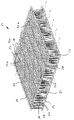
- the spacer fabric 10 has an upper fabric layer 12, a lower fabric layer 14 and a spacer layer 20 arranged therebetween.
- the upper knitted layer 12 is formed as a woven fabric of monofilament base threads 16 into which conductive threads 32a in the warp direction and conductive threads 32b in a weft direction are woven so that they result in a heating loop structure 34 for forming an electrical heating device 30 . Weft and warp directions can also be reversed.
- An electrical contact is formed at the crossing points between the conductive threads 32a, 32b.
- the conductive filaments 32a, 32b are made of a polymeric material which is electrically conductive at ambient temperature and current blocking at a predetermined elevated temperature limit.
- the conductive threads 32 are preferably selected to be the same or largely the same as the non-conductive basic threads 16 of the spacer fabric 10 designed as a three-dimensional fabric in terms of diameter, stretch behavior, strength and/or flexibility.
- the lower knitted fabric layer 14 is also formed as a woven fabric made of non-conductive base threads 16 .
- the upper knitted layer 12 and the lower knitted layer 14 are connected to one another via pile threads 22 of the spacer layer 20 running essentially perpendicular thereto.
- the pile threads 22 can simultaneously serve as ground threads 16 in the upper knitted fabric layer 12 and the lower knitted fabric layer 14 .
- the pile threads 22 are spaced apart from one another in such a way that a free space 24 is formed in the spacer layer 20, through which air can flow, which is shown schematically is indicated by arrows.
- the air flow can be free or forced by a fan device.
- the conductive threads 32 for forming the heating device 30 are incorporated into the fabric of the upper knitted layer 12 . At two contact sections, free end sections of the conductive threads 32 extend downward as pile threads 22 to the lower knitted layer 14 in order to form connections 38 there for an electrical connection to a power source. When current is passed through, due to an internal resistance of the conductive threads 32 of the heating device 30 , heat is generated which can be emitted to the upper side of the spacer fabric 10 . Further conductive threads 32 can preferably also extend as pile threads 22, which are part of the heating device 30, in the region of the spacer layer 20, so that the air flow through the spacer layer 20 can also be heated. This increases the ability of the heated air to absorb moisture. Air flow can also be upward through openings in the woven upper fabric layer 12 .
Landscapes
- Engineering & Computer Science (AREA)
- Aviation & Aerospace Engineering (AREA)
- Transportation (AREA)
- Mechanical Engineering (AREA)
- Textile Engineering (AREA)
- Knitting Of Fabric (AREA)
- Surface Heating Bodies (AREA)
- Chair Legs, Seat Parts, And Backrests (AREA)
Description
- Die Erfindung betrifft ein Abstandsgewirk, insbesondere für ein Sitzpolster, mit einer oberen Gewirklage, einer unteren Gewirklage, welche im Wesentlichen parallel zu der oberen Gewirklage ist, einer Abstandslage, welche zwischen der oberen Gewirklage und der unteren Gewirklage angeordnet und durch Polfäden gebildet ist, welche sich im Wesentlichen senkrecht zu der oberen Gewirklage und der unteren Gewirklage erstrecken und diese verbinden, wobei die Polfäden zum Bilden eines Freiraums zueinander beabstandet sind, welcher durch Luft durchströmbar ist, und eine Heizeinrichtung an der oberen Gewirklage, gemäß dem Oberbegriff des Anspruchs 1.
- Abstandsgewirke mit einer Abstandslage zum Bilden eines Freiraumes für eine Luftdurchströmung bei Fahrzeugsitzen sind seit langem bekannt, etwa aus der
EP 0 868 323 B1 oder derDE 100 13 492 A1 . Durch diesen Freiraum innerhalb des Abstandsgewirks wird eine Luftzirkulation ermöglicht, die für ein angenehmeres Sitzgefühl und zu einer verbesserten Feuchtigkeitsabfuhr führt. - Weiter ist es bekannt, zusätzlich an der Oberseite eines derartigen Abstandsgewirks eine Heizeinrichtung vorzusehen, so dass bei Bedarf auch eine Erwärmung einer Sitzfläche erfolgen kann. Derartige gattungsgemäße Abstandsgewirke gehen beispielsweise aus der
DE 42 39 068 C2 , derDE 299 01 225 U1 oder derEP 2 456 282 B1 hervor. Weiter ist aus derDE 10 2015 114 778 A1 ein Abstandsgewirk für ein beheizbares Verkleidungselement bekannt. - Die
EP 0 202 896 A2 zeigt den Aufbau von Heizelementen, die für diverse Einsatzzwecke in unterschiedlicher Weise aufgebaut sein können. - Heizeinrichtungen für Sitzpolster weisen üblicherweise eine elektrische Heizleiterschleife auf, welche durch elektrischen Strom durchflossen wird, wobei aufgrund eines inneren Widerstandes der Heizleiter Wärme erzeugt wird.
- Der Erfindung liegt die Aufgabe zugrunde, ein Abstandsgewirk anzugeben, welches bei einem einfachen Aufbau sowohl eine gute Durchlüftung als auch ein effizientes Beheizen ermöglicht.
- Die Aufgabe wird nach der Erfindung durch ein Abstandsgewirk mit den Merkmalen des Anspruchs 1 gelöst. Bevorzugte Ausführungsformen der Erfindung sind in den abhängigen Ansprüchen angegeben.
- Das erfindungsgemäße Abstandsgewirk ist dadurch gekennzeichnet, dass die Heizeinrichtung mit leitenden Fäden aus einem Polymermaterial gebildet ist, welches bei Umgebungstemperatur elektrisch leitfähig und bei einer vorgegebenen erhöhten Grenztemperatur stromsperrend ist. Die leitenden Fäden werden somit aus einem Polymermaterial gefertigt, welches bei einer Umgebungstemperatur eine elektrische Stromdurchleitung ermöglicht und dabei aufgrund eines inneren Widerstandes Wärme erzeugt. Bei Erreichen einer vorgegebenen erhöhten Grenztemperatur, welche typischerweise zwischen 40°C bis 70°C betragen kann, verändert sich ein innerer Widerstand des Polymermaterials derart, dass dieses vollständig oder zumindest im Wesentlichen stromsperrend ist. Hierdurch wird ein weiterer Stromdurchfluss und damit eine weitere Wärmedurchleitung unterbunden.
- Bei einem Absinken der Temperatur des leitenden Polymermateriales unter die vorgegebene Grenztemperatur erhält das Material wieder seine elektrische Leitfähigkeit zurück, so dass eine weitere Stromdurchleitung und somit Aufheizung erfolgen kann.
- Hierdurch wird eine materialabhängige Steuerung der Heizleistung erreicht. Darüber hinaus können Fäden aus einem flexiblen Polymermaterial wie andere Fäden zur Herstellung des Abstandsgewirks verarbeitet werden. Hierdurch ergibt sich eine besonders gute Verarbeitbarkeit und Herstellbarkeit des Abstandsgewirks insgesamt.
- Besonders bevorzugt ist es nach einer Weiterbildung der Erfindung, dass die leitenden Fäden aus einem PTC-Material gebildet sind. Es handelt sich hierbei um sogenannten Kaltleitermaterialien, welche einen temperaturabhängigen Widerstand aufweisen und welche grundsätzlich zu der Gruppe der Thermistoren gehören. Derartige Materialien weisen einen positiven Temperaturkoeffizienten auf, bei welchen ein elektrischer Widerstand mit zunehmender Temperatur ansteigt. Das Material ist dabei so ausgewählt, dass dieses bis zu einer vorgesehenen Grenztemperatur von bis zu 70°C unter Abgabe von Wärme stromleitend ist und ab der Grenztemperatur eine signifikante Erhöhung des elektrischen Widerstandes aufweist, so dass ein entsprechender Leiter zumindest im Spannungsbereich für eine Sitzheizung stromsperrend ist.
- Ein entsprechendes Verhalten kann durch eine Zugabe von Silizium, Barium oder anderen geeigneten Elementen bei einem Polymermaterial erzielt werden. Unter Abstandsgewirk im Sinne der Erfindung sind nicht nur Gewirke im eigentlichen Sinne sondern auch Gewebe, Gestricke und Vliese zu verstehen.
- Das erfindungsgemäße Abstandsgewirk ist auch gekennzeichnet dadurch, dass die leitenden Fäden auf die obere Gewirklage aufgebracht sind. Die leitenden Fäden sind somit in eine Fadenstruktur der oberen Gewirklage eingearbeitet.
- Die leitenden Fäden tragen so unmittelbar auch zum Aufbau und zur mechanischen Festigkeit der Gewirklage bei.
- Das erfindungsgemäße Abstandsgewirk ist weiter gekennzeichnet dadurch, dass zumindest ein Teil der Polfäden durch die leitenden Fäden gebildet ist. Hierdurch kann zumindest in einem gewissen Umfang auch im Bereich der Abstands- oder Zwischenlage eine Heizwirkung erzielt werden. Dies ist für einen Abtransport von Feuchtigkeit vorteilhaft und kann insbesondere bei einem Durchtritt von Lüftungsluft durch die obere Gewirklage nach außen für einen zusätzlichen Wärmeeffekt durch Austreten warmer Luft dienen.
- Grundsätzlich kann die Gewirklage ein Gestrick oder ein Vlies sein. Besonders vorteilhaft ist es nach einer Weiterbildung der Erfindung, dass zumindest die obere Gewirklage als eine Gewebelage ausgebildet ist und dass die leitenden Fäden als Schuss- und/oder Kettfäden zusammen mit nicht leitenden Grundfäden zu der oberen Gewirklage verwebt sind. Die leitenden Fäden sind somit unmittelbar Teil der Gewebestruktur der oberen Gewirklage. Dabei können die leitenden Fäden in Schuss- und in Kettrichtung verwebt sein, wobei diese so verwebt sind, dass sich diese an vorgegebenen Punkten kreuzen und dabei eine elektrische Verbindung bilden. Dabei kann eine schleifenartige Struktur gebildet werden, welche als eine Heizstruktur zum Hindurchleiten von elektrischem Strom dienen kann. Die leitenden Fäden können dabei hinsichtlich Durchmesser, Festigkeit und/oder Flexibilität wie die anderen nicht-leitenden Fäden ausgebildet sein, so dass sich eine sehr einheitliche Gewebestruktur ergibt.
- Besonders zweckmäßig ist es dabei, dass die leitenden Fäden in der oberen Gewirklage so verwebt sind, dass diese in einem vorgesehenen Heizbereich mäanderförmig angeordnet sind, wobei eine Heizschleifenstruktur gebildet ist. Dabei sind in einer Geweberichtung eine Vielzahl von leitenden Fäden parallel zueinander in einem oberen Bereich der Gewirklage angeordnet, wobei diese parallelen leitenden Fäden dann wechselweise an Endbereichen mit relativ kürzeren leitenden Verbindungsfäden in Querrichtung gekreuzt, verbunden oder verknüpft sind, so dass sich eine mäanderartige Heizschleifenstruktur in der oberen Gewirklage ergibt.
- Neben einer guten Heizwirkung kann zudem nach einer Weiterbildung der Erfindung eine gute Lüftungsfunktion dadurch erzielt werden, dass zumindest die obere Gewirklage einlagig mit einer offenen Porenstruktur gebildet ist. Die offenen Poren können dabei 10% bis 60% der Gewebefläche bilden. Hierdurch besteht ausreichend Möglichkeit, dass Luft aus der Abstandslage durch das Abstandsgewirk strömt und nach oben aus dem Abstandsgewirk austreten kann. Hierdurch kann eine besonders gute Kühlungsfunktion sowie ein Abtransport von Feuchtigkeit erzielt werden. Insbesondere bei Fahrzeugsitzen kann dies als besonders angenehm empfunden werden. Grundsätzlich können die Fäden in beliebiger Weise aufgebaut sein, insbesondere auch als Multifilfäden. Eine besonders gute Stromleitungsfunktion bei guter Festigkeit wird nach einer Weiterbildung der Erfindung dadurch erzielt, dass die leitenden Fäden als Monofilfäden ausgebildet sind. Die Fäden können dabei einen Fadendurchmesser von vorzugsweise zwischen 100 µm bis 2 mm aufweisen. Unter Monofilfäden sind drahtartige Fäden mit vorzugsweise einem runden Querschnitt zu verstehen. Darüber hinaus können Monofilfäden auch zum Bilden des weiteren Abstandsgewirks vorgesehen sein, insbesondere können die Polfäden, welche sich innerhalb des Abstandsgewirks erstrecken und eine notwendige mechanische Stabilität zum Bilden der räumlichen Struktur der Abstandslage aufweisen müssen, ebenfalls als Monofilfäden vorgesehen sein.
- Eine besonders stabile Konstruktion des Abstandsgewirks wird nach einer Variante der Erfindung dadurch erzielt, dass dieses insgesamt als ein dreidimensionales Gewebe gebildet ist. Somit kann das Abstandsgewirk insgesamt auf einer Webmaschine als ein dreidimensionales Gewebe mit mehreren Gewebelagen hergestellt werden. Auf dieser Webmaschine werden dann ein Teil der Fäden als leitende Fäden in Schuss- und/oder Kettrichtung verwebt. Die weiteren nicht-leitenden Fäden können dabei sogenannte Strukturfäden sein, welche maßgeblich zur mechanischen Festigkeit und auch zum Bilden einer Gewebeoberfläche in einem gewissen Dekor beitragen oder diese maßgeblich bestimmen. Insbesondere an der Oberseite der oberen Gewirklage sind die leitenden Fäden so integriert, dass eine gute Abgabe der Heizleistung an der Oberseite gegeben ist. Die leitenden Fäden können an ihrer Außenseite mit einer isolierenden Umhüllung versehen sein, welche allenfalls im Bereich der Verbindungsabschnitte zum Bilden einer leitenden Verbindung entfernt ist.
- Die Erfindung umfasst auch einen Sitz, insbesondere einen Fahrzeugsitz mit zumindest einem Sitzteil und einem Rückenteil, wobei die Erfindung dadurch gekennzeichnet ist, dass das Sitzteil und/oder das Rückenteil ein erfindungsgemäßes Abstandsgewirk aufweist, so wie dieses zuvor beschrieben ist. Bei einem derartigen Sitz können die zuvor beschriebenen Vorteile erzielt werden. Der Fahrzeugsitz ist insbesondere für ein Automobil vorgesehen.
- Eine bevorzugte Weiterbildung des erfindungsgemäßen Sitzes besteht darin, dass zumindest eine Lüftereinrichtung vorgesehen ist, durch welche eine Luftströmung in der Abstandslage zum Abstandsgewirk erzeugbar ist. Die Lüftereinrichtung kann dabei einen oder mehrere elektrisch betriebene Lüfter aufweisen, welche eine Luftströmung in der Abstandslage erzeugen. Bei einer entsprechenden Porenstruktur der oberen Gewirklage kann vorzugsweise die Luft aus der Oberseite in Richtung auf eine auf dem Sitz sitzende Person ausströmen.
- Besonders vorteilhaft ist es nach einer weiteren Ausführungsform der Erfindung, dass elektrische Anschlüsse an der unteren Gewirklage für die leitfähigen Fäden angeordnet sind, wobei sich zumindest zwei leitfähige Fäden als Polfäden von der oberen Gewirklage zur unteren Gewirklage erstrecken und mit den elektrischen Anschlüssen verbunden sind. Die elektrischen Anschlüsse sind dabei vorzugsweise mit Steckelementen ausgebildet, so dass diese mit entsprechenden Steckern einer Stromversorgung verbunden werden können. Insbesondere können die Anschlüsse für eine 12 V oder 24 V Stromversorgung vorgesehen sein.
- Die Erfindung wird nachfolgend anhand eines bevorzugten Ausführungsbeispiels weiter beschrieben, welches schematisch in der Zeichnung dargestellt ist.
- In der einzigen Figurenzeichnung ist eine perspektivische Ansicht eines erfindungsgemäßen Abstandsgewirks 10 dargestellt. Das Abstandsgewirk 10 weist eine obere Gewirklage 12, eine untere Gewirklage 14 und eine dazwischen angeordnete Abstandslage 20 auf. Die obere Gewirklage 12 ist als ein Gewebe aus monofilen Grundfäden 16 ausgebildet, in welche leitende Fäden 32a in Kettrichtung und leitende Fäden 32b in einer Schussrichtung so eingewebt sind, so dass sie eine Heizschleifenstruktur 34 zum Bilden einer elektrischen Heizeinrichtung 30 ergeben. Schuss- und Kettrichtung können auch vertauscht sein. An den Kreuzungspunkten zwischen den leitenden Fäden 32a, 32b ist ein elektrischer Kontakt gebildet. Die leitenden Fäden 32a, 32b sind aus einem Polymermaterial gefertigt, welches bei Umgebungstemperatur elektrisch leitfähig und bei einer vorgegebenen erhöhten Grenztemperatur stromsperrend ist.
- Die leitenden Fäden 32 sind dabei vorzugsweise hinsichtlich Durchmesser, Dehnungsverhalten, Festigkeit und/oder Flexibilität gleich oder weitgehend gleich zu den nicht leitenden Grundfäden 16 des als dreidimensionales Gewebe ausgebildeten Abstandsgewirks 10 ausgewählt.
- Die untere Gewirklage 14 ist in dem dargestellten Ausführungsbeispiel ebenfalls als ein Gewebe aus nicht leitenden Grundfäden 16 gebildet. Die obere Gewirklage 12 und die untere Gewirklage 14 sind über im Wesentlichen senkrecht dazu verlaufende Polfäden 22 der Abstandslage 20 miteinander verbunden. Die Polfäden 22 können gleichzeitig als Grundfäden 16 in der oberen Gewirklage 12 und der unteren Gewirklage 14 dienen.
- Die Polfäden 22 sind so voneinander beabstandet, dass in der Abstandslage 20 ein Freiraum 24 ausgebildet ist, welcher von Luft durchströmbar ist, was schematisch durch Pfeile angedeutet ist. Die Luftströmung kann frei oder durch eine Lüftereinrichtung erzwungen sein.
- Die leitenden Fäden 32 zum Bilden der Heizeinrichtung 30 sind in das Gewebe der oberen Gewirklage 12 eingearbeitet. An zwei Kontaktabschnitten erstrecken sich freie Endabschnitte der leitenden Fäden 32 als Polfäden 22 nach unten zur unteren Gewirklage 14, um dort Anschlüsse 38 für eine elektrische Verbindung mit einer Stromquelle zu bilden. Bei einem Durchleiten von Strom ergibt sich aufgrund eines inneren Widerstandes der leitenden Fäden 32 der Heizeinrichtung 30 eine Wärmeentwicklung, welche zur Oberseite des Abstandsgewirks 10 abgegeben werden kann. Bevorzugt können sich auch weitere leitende Fäden 32 als Polfäden 22, welche Teil der Heizeinrichtung 30 sind, im Bereich des Abstandslage 20 erstrecken, so dass auch eine Erwärmung der Luftdurchströmung durch die Abstandslage 20 erfolgen kann. Hierdurch steigt die Aufnahmefähigkeit der erwärmten Luft für Feuchtigkeit. Die Luftdurchströmung kann auch nach oben durch Öffnungen in der gewebten oberen Gewirklage 12 erfolgen.
- Bei Erreichen einer vorgegebenen höheren Grenztemperatur der leitenden Fäden 32 können diese aufgrund ihrer Kaltleitereigenschaft stromsperrend werden, so dass sich ohne eine aufwändige elektrische Steuerung eine materialinterne Temperaturregulierung ergibt.
Claims (10)
- Abstandsgewirk, insbesondere für ein Sitzpolster, mit- einer oberen Gewirklage (12),- einer unteren Gewirklage (14), welche im Wesentlichen parallel zu der oberen Gewirklage (12) ist,- einer Abstandslage (20), welche zwischen der oberen Gewirklage (12) und der unteren Gewirklage (14) angeordnet und durch Polfäden (22) gebildet ist, welche sich im Wesentlichen senkrecht zu der oberen Gewirklage (12) und der unteren Gewirklage (14) erstrecken und diese verbinden, wobei die Polfäden (22) zum Bilden eines Freiraums (24) zueinander beabstandet sind, welcher durch Luft durchströmbar ist, und- einer Heizeinrichtung (30) an der oberen Gewirklage (12),dadurch gekennzeichnet,dass die Heizeinrichtung (30) mit leitenden Fäden (32) aus einem Polymermaterial gebildet ist, welches bei Umgebungstemperatur elektrisch leitfähig und bei einer vorgegebenen erhöhten Grenztemperatur stromsperrend ist,dass die leitenden Fäden (32) in eine Fadenstruktur der oberen Gewirklage (12) eingearbeitet sind, unddass zumindest ein Teil der Polfäden (22) durch die leitenden Fäden (32) gebildet ist.
- Abstandsgewirk nach Anspruch 1,
dadurch gekennzeichnet,
dass die leitenden Fäden (32) aus einem PTC-Material gebildet sind. - Abstandsgewirk nach Anspruch 1 bis 2,
dadurch gekennzeichnet,dass zumindest die obere Gewirklage (12) als eine Gewebelage ausgebildet ist unddass die leitenden Fäden (32) als Schuss- und/oder Kettfäden zusammen mit nicht leitenden Grundfäden (16) zu der oberen Gewirklage (12) verwebt sind. - Abstandsgewirk nach Anspruch 3,
dadurch gekennzeichnet,
dass die leitenden Fäden (32) in der oberen Gewirklage (12) so verwebt sind, dass diese in einem vorgesehenen Heizbereich mäanderförmig angeordnet sind, wobei eine Heizschleifenstruktur (34) gebildet ist. - Abstandsgewirk nach Anspruch 3 oder 4,
dadurch gekennzeichnet,
dass zumindest die obere Gewirklage (12) einlagig mit einer offenen Porenstruktur gebildet ist. - Abstandsgewirk nach einem der Ansprüche 1 bis 5,
dadurch gekennzeichnet,
dass die leitenden Fäden (32) als Monofilfäden ausgebildet sind. - Abstandsgewirk nach einem der Ansprüche 1 bis 6,
dadurch gekennzeichnet,
dass dieses insgesamt als ein dreidimensionales Gewebe gebildet ist. - Sitz, insbesondere Fahrzeugsitz, mit zumindest einem Sitzteil und einem Rückenteil,
dadurch gekennzeichnet,
dass das Sitzteil und/oder das Rückenteil ein Abstandsgewirk (10) nach einem der Ansprüche 1 bis 7 aufweist. - Sitz nach Anspruch 8,
dadurch gekennzeichnet,
dass mindestens eine Lüftereinrichtung vorgesehen ist, durch welche eine Luftströmung in der Abstandslage (20) des Abstandsgewirks (10) erzeugbar ist. - Sitz nach Anspruch 8 oder 9,
dadurch gekennzeichnet,
dass elektrische Anschlüsse (38) an der unteren Gewirklage (14) für die leitenden Fäden (32) angeordnet sind, wobei sich zumindest zwei leitende Fäden (32) als Polfäden (22) von der oberen Gewirklage (12) zur unteren Gewirklage (14) erstrecken und mit den elektrischen Anschlüssen (38) verbunden sind.
Priority Applications (4)
| Application Number | Priority Date | Filing Date | Title |
|---|---|---|---|
| EP20167888.5A EP3890435B1 (de) | 2020-04-03 | 2020-04-03 | Abstandsgewirk, insbesondere für ein sitzpolster |
| PL20167888.5T PL3890435T3 (pl) | 2020-04-03 | 2020-04-03 | Tkanina dystansowa, w szczególności dla tapicerki siedziska |
| ES20167888T ES2937072T3 (es) | 2020-04-03 | 2020-04-03 | Malla espaciadora, en particular para un acolchado de asiento |
| PCT/EP2021/051729 WO2021197680A1 (de) | 2020-04-03 | 2021-01-26 | Abstandsgewirk, insbesondere für ein sitzpolster |
Applications Claiming Priority (1)
| Application Number | Priority Date | Filing Date | Title |
|---|---|---|---|
| EP20167888.5A EP3890435B1 (de) | 2020-04-03 | 2020-04-03 | Abstandsgewirk, insbesondere für ein sitzpolster |
Publications (2)
| Publication Number | Publication Date |
|---|---|
| EP3890435A1 EP3890435A1 (de) | 2021-10-06 |
| EP3890435B1 true EP3890435B1 (de) | 2022-12-21 |
Family
ID=70165924
Family Applications (1)
| Application Number | Title | Priority Date | Filing Date |
|---|---|---|---|
| EP20167888.5A Active EP3890435B1 (de) | 2020-04-03 | 2020-04-03 | Abstandsgewirk, insbesondere für ein sitzpolster |
Country Status (4)
| Country | Link |
|---|---|
| EP (1) | EP3890435B1 (de) |
| ES (1) | ES2937072T3 (de) |
| PL (1) | PL3890435T3 (de) |
| WO (1) | WO2021197680A1 (de) |
Citations (2)
| Publication number | Priority date | Publication date | Assignee | Title |
|---|---|---|---|---|
| EP0202896B1 (de) * | 1985-05-17 | 1991-09-04 | RAYCHEM CORPORATION (a Delaware corporation) | Elektrisches Folienheizelement |
| DE10013492A1 (de) * | 2000-03-20 | 2001-09-27 | Cetex Chemnitzer Textilmaschin | Fahrzeugsitz |
Family Cites Families (6)
| Publication number | Priority date | Publication date | Assignee | Title |
|---|---|---|---|---|
| DE4239068C2 (de) | 1992-11-20 | 1996-03-14 | Peter Rickerl | Abstandsgewirke zur Aufpolsterung |
| DE69603976T2 (de) | 1995-12-22 | 2000-04-06 | Hoechst Celanese Corp. | Fahrzeugsitz mit hoher luftzirkulation und darin verwendete materialien |
| DE29901225U1 (de) | 1998-01-26 | 1999-05-12 | Müller, Peter, 83209 Prien | Abstandsgewirke zur Aufpolsterung |
| EP2456282B1 (de) | 2010-11-18 | 2012-09-12 | Mattes & Ammann GmbH & Co. KG | Abstandsgewirk oder -gestrick für Heizzwecke, Verfahren zu seiner Herstellung und Verwendung desselben |
| DE102012012285A1 (de) * | 2012-06-20 | 2012-12-13 | Daimler Ag | Verkleidungselement für einen Innenraum eines Kraftwagens |
| DE102015114778B4 (de) * | 2015-09-03 | 2025-08-21 | Müller Textil GmbH | Abstandsgewirke, Abstandsgewirkeabschnitt sowie beheizbares Verkleidungselement |
-
2020
- 2020-04-03 PL PL20167888.5T patent/PL3890435T3/pl unknown
- 2020-04-03 EP EP20167888.5A patent/EP3890435B1/de active Active
- 2020-04-03 ES ES20167888T patent/ES2937072T3/es active Active
-
2021
- 2021-01-26 WO PCT/EP2021/051729 patent/WO2021197680A1/de not_active Ceased
Patent Citations (2)
| Publication number | Priority date | Publication date | Assignee | Title |
|---|---|---|---|---|
| EP0202896B1 (de) * | 1985-05-17 | 1991-09-04 | RAYCHEM CORPORATION (a Delaware corporation) | Elektrisches Folienheizelement |
| DE10013492A1 (de) * | 2000-03-20 | 2001-09-27 | Cetex Chemnitzer Textilmaschin | Fahrzeugsitz |
Also Published As
| Publication number | Publication date |
|---|---|
| ES2937072T3 (es) | 2023-03-23 |
| EP3890435A1 (de) | 2021-10-06 |
| WO2021197680A1 (de) | 2021-10-07 |
| PL3890435T3 (pl) | 2023-03-13 |
Similar Documents
| Publication | Publication Date | Title |
|---|---|---|
| EP1777992B1 (de) | Flexibles Flächenheizelement, insbesondere für Sitzheizungen, und Verfahren zur Herstellung eines flexiblen Heizelements | |
| DE102008020391B4 (de) | Heizmatte mit reduziertem Stromverbrauch | |
| DE102006026047B4 (de) | Heizelement, Sitz und Fahrzeug mit einem solchen | |
| EP0532468B1 (de) | Elektrisches Heizelement | |
| EP0463516A2 (de) | Elektrisches Flächenheizelement | |
| DE102015114778B4 (de) | Abstandsgewirke, Abstandsgewirkeabschnitt sowie beheizbares Verkleidungselement | |
| EP1907238A1 (de) | Kraftfahrzeugsitz mit einer belüftungseinrichtung | |
| DE102018120999B4 (de) | Abstandsgewirke | |
| DE102007027828A1 (de) | Modul für ein Polster | |
| EP0991347B1 (de) | Stützteil für einen sitz | |
| WO1995001082A1 (de) | Flächenheizelement | |
| WO2007048520A2 (de) | Flächenheizelement für einen kraftfahrzeugsitz | |
| EP3890435B1 (de) | Abstandsgewirk, insbesondere für ein sitzpolster | |
| EP1851075B1 (de) | Heizvorrichtung zum erwärmen eines luftstroms insbesondere für ein karftfahrzeug | |
| DE10319048A1 (de) | Einlage zur Klimatisierung | |
| DE102008034815A1 (de) | Elektrisches Flächenheizelement sowie Verfahren zur Herstellung eines elektrischen Flächenheizelementes | |
| DE202006011524U1 (de) | Textiles Polflächengebilde | |
| DE102005035113B4 (de) | Kraftfahrzeugsitz mit einer Luftversorgungseinrichtung | |
| DE102005035116B3 (de) | Kraftahrzeugsitz mit einer Belüftungseinrichtung | |
| DE202007010960U1 (de) | Vorrichtung zum Heizen | |
| DE202005008878U1 (de) | Beheizbare Wickelunterlage | |
| DE102004010213B4 (de) | Elektrisches, flexibles Flächenheizelement aus Carbon-Geflecht | |
| DE202006004033U1 (de) | Heizgewebe | |
| DE3914897C2 (de) | ||
| DE202007008484U1 (de) | Modul für ein Polster |
Legal Events
| Date | Code | Title | Description |
|---|---|---|---|
| STAA | Information on the status of an ep patent application or granted ep patent |
Free format text: STATUS: EXAMINATION IS IN PROGRESS |
|
| PUAI | Public reference made under article 153(3) epc to a published international application that has entered the european phase |
Free format text: ORIGINAL CODE: 0009012 |
|
| 17P | Request for examination filed |
Effective date: 20201022 |
|
| AK | Designated contracting states |
Kind code of ref document: A1 Designated state(s): AL AT BE BG CH CY CZ DE DK EE ES FI FR GB GR HR HU IE IS IT LI LT LU LV MC MK MT NL NO PL PT RO RS SE SI SK SM TR |
|
| GRAP | Despatch of communication of intention to grant a patent |
Free format text: ORIGINAL CODE: EPIDOSNIGR1 |
|
| STAA | Information on the status of an ep patent application or granted ep patent |
Free format text: STATUS: GRANT OF PATENT IS INTENDED |
|
| INTG | Intention to grant announced |
Effective date: 20220719 |
|
| GRAS | Grant fee paid |
Free format text: ORIGINAL CODE: EPIDOSNIGR3 |
|
| GRAA | (expected) grant |
Free format text: ORIGINAL CODE: 0009210 |
|
| STAA | Information on the status of an ep patent application or granted ep patent |
Free format text: STATUS: THE PATENT HAS BEEN GRANTED |
|
| AK | Designated contracting states |
Kind code of ref document: B1 Designated state(s): AL AT BE BG CH CY CZ DE DK EE ES FI FR GB GR HR HU IE IS IT LI LT LU LV MC MK MT NL NO PL PT RO RS SE SI SK SM TR |
|
| REG | Reference to a national code |
Ref country code: GB Ref legal event code: FG4D Free format text: NOT ENGLISH |
|
| REG | Reference to a national code |
Ref country code: CH Ref legal event code: EP |
|
| REG | Reference to a national code |
Ref country code: DE Ref legal event code: R096 Ref document number: 502020002217 Country of ref document: DE |
|
| REG | Reference to a national code |
Ref country code: AT Ref legal event code: REF Ref document number: 1539832 Country of ref document: AT Kind code of ref document: T Effective date: 20230115 |
|
| REG | Reference to a national code |
Ref country code: IE Ref legal event code: FG4D Free format text: LANGUAGE OF EP DOCUMENT: GERMAN |
|
| REG | Reference to a national code |
Ref country code: RO Ref legal event code: EPE |
|
| REG | Reference to a national code |
Ref country code: ES Ref legal event code: FG2A Ref document number: 2937072 Country of ref document: ES Kind code of ref document: T3 Effective date: 20230323 |
|
| REG | Reference to a national code |
Ref country code: LT Ref legal event code: MG9D |
|
| REG | Reference to a national code |
Ref country code: NL Ref legal event code: MP Effective date: 20221221 |
|
| PG25 | Lapsed in a contracting state [announced via postgrant information from national office to epo] |
Ref country code: SE Free format text: LAPSE BECAUSE OF FAILURE TO SUBMIT A TRANSLATION OF THE DESCRIPTION OR TO PAY THE FEE WITHIN THE PRESCRIBED TIME-LIMIT Effective date: 20221221 Ref country code: NO Free format text: LAPSE BECAUSE OF FAILURE TO SUBMIT A TRANSLATION OF THE DESCRIPTION OR TO PAY THE FEE WITHIN THE PRESCRIBED TIME-LIMIT Effective date: 20230321 Ref country code: LT Free format text: LAPSE BECAUSE OF FAILURE TO SUBMIT A TRANSLATION OF THE DESCRIPTION OR TO PAY THE FEE WITHIN THE PRESCRIBED TIME-LIMIT Effective date: 20221221 Ref country code: FI Free format text: LAPSE BECAUSE OF FAILURE TO SUBMIT A TRANSLATION OF THE DESCRIPTION OR TO PAY THE FEE WITHIN THE PRESCRIBED TIME-LIMIT Effective date: 20221221 |
|
| PG25 | Lapsed in a contracting state [announced via postgrant information from national office to epo] |
Ref country code: RS Free format text: LAPSE BECAUSE OF FAILURE TO SUBMIT A TRANSLATION OF THE DESCRIPTION OR TO PAY THE FEE WITHIN THE PRESCRIBED TIME-LIMIT Effective date: 20221221 Ref country code: LV Free format text: LAPSE BECAUSE OF FAILURE TO SUBMIT A TRANSLATION OF THE DESCRIPTION OR TO PAY THE FEE WITHIN THE PRESCRIBED TIME-LIMIT Effective date: 20221221 Ref country code: HR Free format text: LAPSE BECAUSE OF FAILURE TO SUBMIT A TRANSLATION OF THE DESCRIPTION OR TO PAY THE FEE WITHIN THE PRESCRIBED TIME-LIMIT Effective date: 20221221 Ref country code: GR Free format text: LAPSE BECAUSE OF FAILURE TO SUBMIT A TRANSLATION OF THE DESCRIPTION OR TO PAY THE FEE WITHIN THE PRESCRIBED TIME-LIMIT Effective date: 20230322 |
|
| P01 | Opt-out of the competence of the unified patent court (upc) registered |
Effective date: 20230427 |
|
| PG25 | Lapsed in a contracting state [announced via postgrant information from national office to epo] |
Ref country code: NL Free format text: LAPSE BECAUSE OF FAILURE TO SUBMIT A TRANSLATION OF THE DESCRIPTION OR TO PAY THE FEE WITHIN THE PRESCRIBED TIME-LIMIT Effective date: 20221221 |
|
| PG25 | Lapsed in a contracting state [announced via postgrant information from national office to epo] |
Ref country code: SM Free format text: LAPSE BECAUSE OF FAILURE TO SUBMIT A TRANSLATION OF THE DESCRIPTION OR TO PAY THE FEE WITHIN THE PRESCRIBED TIME-LIMIT Effective date: 20221221 Ref country code: PT Free format text: LAPSE BECAUSE OF FAILURE TO SUBMIT A TRANSLATION OF THE DESCRIPTION OR TO PAY THE FEE WITHIN THE PRESCRIBED TIME-LIMIT Effective date: 20230421 Ref country code: EE Free format text: LAPSE BECAUSE OF FAILURE TO SUBMIT A TRANSLATION OF THE DESCRIPTION OR TO PAY THE FEE WITHIN THE PRESCRIBED TIME-LIMIT Effective date: 20221221 Ref country code: CZ Free format text: LAPSE BECAUSE OF FAILURE TO SUBMIT A TRANSLATION OF THE DESCRIPTION OR TO PAY THE FEE WITHIN THE PRESCRIBED TIME-LIMIT Effective date: 20221221 |
|
| PG25 | Lapsed in a contracting state [announced via postgrant information from national office to epo] |
Ref country code: SK Free format text: LAPSE BECAUSE OF FAILURE TO SUBMIT A TRANSLATION OF THE DESCRIPTION OR TO PAY THE FEE WITHIN THE PRESCRIBED TIME-LIMIT Effective date: 20221221 Ref country code: IS Free format text: LAPSE BECAUSE OF FAILURE TO SUBMIT A TRANSLATION OF THE DESCRIPTION OR TO PAY THE FEE WITHIN THE PRESCRIBED TIME-LIMIT Effective date: 20230421 Ref country code: AL Free format text: LAPSE BECAUSE OF FAILURE TO SUBMIT A TRANSLATION OF THE DESCRIPTION OR TO PAY THE FEE WITHIN THE PRESCRIBED TIME-LIMIT Effective date: 20221221 |
|
| REG | Reference to a national code |
Ref country code: DE Ref legal event code: R097 Ref document number: 502020002217 Country of ref document: DE |
|
| PLBE | No opposition filed within time limit |
Free format text: ORIGINAL CODE: 0009261 |
|
| STAA | Information on the status of an ep patent application or granted ep patent |
Free format text: STATUS: NO OPPOSITION FILED WITHIN TIME LIMIT |
|
| PG25 | Lapsed in a contracting state [announced via postgrant information from national office to epo] |
Ref country code: DK Free format text: LAPSE BECAUSE OF FAILURE TO SUBMIT A TRANSLATION OF THE DESCRIPTION OR TO PAY THE FEE WITHIN THE PRESCRIBED TIME-LIMIT Effective date: 20221221 |
|
| 26N | No opposition filed |
Effective date: 20230922 |
|
| PG25 | Lapsed in a contracting state [announced via postgrant information from national office to epo] |
Ref country code: MC Free format text: LAPSE BECAUSE OF FAILURE TO SUBMIT A TRANSLATION OF THE DESCRIPTION OR TO PAY THE FEE WITHIN THE PRESCRIBED TIME-LIMIT Effective date: 20221221 |
|
| PG25 | Lapsed in a contracting state [announced via postgrant information from national office to epo] |
Ref country code: SI Free format text: LAPSE BECAUSE OF FAILURE TO SUBMIT A TRANSLATION OF THE DESCRIPTION OR TO PAY THE FEE WITHIN THE PRESCRIBED TIME-LIMIT Effective date: 20221221 Ref country code: MC Free format text: LAPSE BECAUSE OF FAILURE TO SUBMIT A TRANSLATION OF THE DESCRIPTION OR TO PAY THE FEE WITHIN THE PRESCRIBED TIME-LIMIT Effective date: 20221221 |
|
| PG25 | Lapsed in a contracting state [announced via postgrant information from national office to epo] |
Ref country code: IT Free format text: LAPSE BECAUSE OF FAILURE TO SUBMIT A TRANSLATION OF THE DESCRIPTION OR TO PAY THE FEE WITHIN THE PRESCRIBED TIME-LIMIT Effective date: 20221221 |
|
| PG25 | Lapsed in a contracting state [announced via postgrant information from national office to epo] |
Ref country code: BG Free format text: LAPSE BECAUSE OF FAILURE TO SUBMIT A TRANSLATION OF THE DESCRIPTION OR TO PAY THE FEE WITHIN THE PRESCRIBED TIME-LIMIT Effective date: 20221221 |
|
| PG25 | Lapsed in a contracting state [announced via postgrant information from national office to epo] |
Ref country code: BG Free format text: LAPSE BECAUSE OF FAILURE TO SUBMIT A TRANSLATION OF THE DESCRIPTION OR TO PAY THE FEE WITHIN THE PRESCRIBED TIME-LIMIT Effective date: 20221221 |
|
| PGFP | Annual fee paid to national office [announced via postgrant information from national office to epo] |
Ref country code: LU Payment date: 20250417 Year of fee payment: 6 |
|
| PGFP | Annual fee paid to national office [announced via postgrant information from national office to epo] |
Ref country code: DE Payment date: 20250430 Year of fee payment: 6 |
|
| PGFP | Annual fee paid to national office [announced via postgrant information from national office to epo] |
Ref country code: ES Payment date: 20250519 Year of fee payment: 6 |
|
| PGFP | Annual fee paid to national office [announced via postgrant information from national office to epo] |
Ref country code: BE Payment date: 20250422 Year of fee payment: 6 |
|
| PGFP | Annual fee paid to national office [announced via postgrant information from national office to epo] |
Ref country code: FR Payment date: 20250422 Year of fee payment: 6 |
|
| PGFP | Annual fee paid to national office [announced via postgrant information from national office to epo] |
Ref country code: CH Payment date: 20250501 Year of fee payment: 6 |
|
| PGFP | Annual fee paid to national office [announced via postgrant information from national office to epo] |
Ref country code: AT Payment date: 20250416 Year of fee payment: 6 |
|
| PG25 | Lapsed in a contracting state [announced via postgrant information from national office to epo] |
Ref country code: CY Free format text: LAPSE BECAUSE OF FAILURE TO SUBMIT A TRANSLATION OF THE DESCRIPTION OR TO PAY THE FEE WITHIN THE PRESCRIBED TIME-LIMIT; INVALID AB INITIO Effective date: 20200403 |
|
| PGFP | Annual fee paid to national office [announced via postgrant information from national office to epo] |
Ref country code: IE Payment date: 20250428 Year of fee payment: 6 |
|
| PG25 | Lapsed in a contracting state [announced via postgrant information from national office to epo] |
Ref country code: HU Free format text: LAPSE BECAUSE OF FAILURE TO SUBMIT A TRANSLATION OF THE DESCRIPTION OR TO PAY THE FEE WITHIN THE PRESCRIBED TIME-LIMIT; INVALID AB INITIO Effective date: 20200403 |
|
| PGFP | Annual fee paid to national office [announced via postgrant information from national office to epo] |
Ref country code: GB Payment date: 20260327 Year of fee payment: 7 |
|
| PGFP | Annual fee paid to national office [announced via postgrant information from national office to epo] |
Ref country code: RO Payment date: 20260327 Year of fee payment: 7 |
|
| PGFP | Annual fee paid to national office [announced via postgrant information from national office to epo] |
Ref country code: TR Payment date: 20260331 Year of fee payment: 7 |
|
| PGFP | Annual fee paid to national office [announced via postgrant information from national office to epo] |
Ref country code: PL Payment date: 20260325 Year of fee payment: 7 |