EP3890435B1 - Maillage de séparation, en particulier pour un coussin d'assise - Google Patents
Maillage de séparation, en particulier pour un coussin d'assise Download PDFInfo
- Publication number
- EP3890435B1 EP3890435B1 EP20167888.5A EP20167888A EP3890435B1 EP 3890435 B1 EP3890435 B1 EP 3890435B1 EP 20167888 A EP20167888 A EP 20167888A EP 3890435 B1 EP3890435 B1 EP 3890435B1
- Authority
- EP
- European Patent Office
- Prior art keywords
- threads
- fabric layer
- spacer
- layer
- fabric
- Prior art date
- Legal status (The legal status is an assumption and is not a legal conclusion. Google has not performed a legal analysis and makes no representation as to the accuracy of the status listed.)
- Active
Links
- 239000004744 fabric Substances 0.000 title claims description 77
- 125000006850 spacer group Chemical group 0.000 title claims description 50
- 238000010438 heat treatment Methods 0.000 claims description 26
- 239000000463 material Substances 0.000 claims description 8
- 239000002861 polymer material Substances 0.000 claims description 7
- 239000002759 woven fabric Substances 0.000 claims description 5
- 239000011148 porous material Substances 0.000 claims description 4
- 238000009423 ventilation Methods 0.000 claims description 4
- 239000010410 layer Substances 0.000 claims 19
- 239000002356 single layer Substances 0.000 claims 1
- 239000004020 conductor Substances 0.000 description 3
- 230000001419 dependent effect Effects 0.000 description 3
- 230000000694 effects Effects 0.000 description 3
- 238000009941 weaving Methods 0.000 description 2
- 229910052788 barium Inorganic materials 0.000 description 1
- DSAJWYNOEDNPEQ-UHFFFAOYSA-N barium atom Chemical compound [Ba] DSAJWYNOEDNPEQ-UHFFFAOYSA-N 0.000 description 1
- 230000015572 biosynthetic process Effects 0.000 description 1
- 230000000903 blocking effect Effects 0.000 description 1
- 238000005253 cladding Methods 0.000 description 1
- 229920001940 conductive polymer Polymers 0.000 description 1
- 238000010276 construction Methods 0.000 description 1
- 238000001816 cooling Methods 0.000 description 1
- 230000005611 electricity Effects 0.000 description 1
- 229920005570 flexible polymer Polymers 0.000 description 1
- 229910052710 silicon Inorganic materials 0.000 description 1
- 239000010703 silicon Substances 0.000 description 1
Images
Classifications
-
- H—ELECTRICITY
- H05—ELECTRIC TECHNIQUES NOT OTHERWISE PROVIDED FOR
- H05B—ELECTRIC HEATING; ELECTRIC LIGHT SOURCES NOT OTHERWISE PROVIDED FOR; CIRCUIT ARRANGEMENTS FOR ELECTRIC LIGHT SOURCES, IN GENERAL
- H05B3/00—Ohmic-resistance heating
- H05B3/10—Heating elements characterised by the composition or nature of the materials or by the arrangement of the conductor
- H05B3/12—Heating elements characterised by the composition or nature of the materials or by the arrangement of the conductor characterised by the composition or nature of the conductive material
- H05B3/14—Heating elements characterised by the composition or nature of the materials or by the arrangement of the conductor characterised by the composition or nature of the conductive material the material being non-metallic
- H05B3/146—Conductive polymers, e.g. polyethylene, thermoplastics
-
- B—PERFORMING OPERATIONS; TRANSPORTING
- B60—VEHICLES IN GENERAL
- B60N—SEATS SPECIALLY ADAPTED FOR VEHICLES; VEHICLE PASSENGER ACCOMMODATION NOT OTHERWISE PROVIDED FOR
- B60N2/00—Seats specially adapted for vehicles; Arrangement or mounting of seats in vehicles
- B60N2/56—Heating or ventilating devices
- B60N2/5607—Heating or ventilating devices characterised by convection
- B60N2/5621—Heating or ventilating devices characterised by convection by air
- B60N2/5642—Heating or ventilating devices characterised by convection by air with circulation of air through a layer inside the seat
-
- B—PERFORMING OPERATIONS; TRANSPORTING
- B60—VEHICLES IN GENERAL
- B60N—SEATS SPECIALLY ADAPTED FOR VEHICLES; VEHICLE PASSENGER ACCOMMODATION NOT OTHERWISE PROVIDED FOR
- B60N2/00—Seats specially adapted for vehicles; Arrangement or mounting of seats in vehicles
- B60N2/56—Heating or ventilating devices
- B60N2/5678—Heating or ventilating devices characterised by electrical systems
- B60N2/5685—Resistance
-
- H—ELECTRICITY
- H05—ELECTRIC TECHNIQUES NOT OTHERWISE PROVIDED FOR
- H05B—ELECTRIC HEATING; ELECTRIC LIGHT SOURCES NOT OTHERWISE PROVIDED FOR; CIRCUIT ARRANGEMENTS FOR ELECTRIC LIGHT SOURCES, IN GENERAL
- H05B3/00—Ohmic-resistance heating
- H05B3/20—Heating elements having extended surface area substantially in a two-dimensional plane, e.g. plate-heater
- H05B3/34—Heating elements having extended surface area substantially in a two-dimensional plane, e.g. plate-heater flexible, e.g. heating nets or webs
- H05B3/342—Heating elements having extended surface area substantially in a two-dimensional plane, e.g. plate-heater flexible, e.g. heating nets or webs heaters used in textiles
- H05B3/347—Heating elements having extended surface area substantially in a two-dimensional plane, e.g. plate-heater flexible, e.g. heating nets or webs heaters used in textiles woven fabrics
-
- H—ELECTRICITY
- H05—ELECTRIC TECHNIQUES NOT OTHERWISE PROVIDED FOR
- H05B—ELECTRIC HEATING; ELECTRIC LIGHT SOURCES NOT OTHERWISE PROVIDED FOR; CIRCUIT ARRANGEMENTS FOR ELECTRIC LIGHT SOURCES, IN GENERAL
- H05B2203/00—Aspects relating to Ohmic resistive heating covered by group H05B3/00
- H05B2203/02—Heaters using heating elements having a positive temperature coefficient
-
- H—ELECTRICITY
- H05—ELECTRIC TECHNIQUES NOT OTHERWISE PROVIDED FOR
- H05B—ELECTRIC HEATING; ELECTRIC LIGHT SOURCES NOT OTHERWISE PROVIDED FOR; CIRCUIT ARRANGEMENTS FOR ELECTRIC LIGHT SOURCES, IN GENERAL
- H05B2203/00—Aspects relating to Ohmic resistive heating covered by group H05B3/00
- H05B2203/029—Heaters specially adapted for seat warmers
Definitions
- the invention relates to a spacer fabric, in particular for a seat cushion, with an upper fabric layer, a lower fabric layer which is essentially parallel to the upper fabric layer, a spacer layer which is arranged between the upper fabric layer and the lower fabric layer and is formed by pile threads which extend essentially perpendicularly to the upper knitted layer and the lower knitted layer and connect them, wherein the pile threads are spaced apart from one another to form a free space through which air can flow, and a heating device on the upper knitted layer, according to the preamble of claim 1.
- Spacer fabrics with a spacer layer to form a free space for air to flow through vehicle seats have long been known, for example from EP 0 868 323 B1 or the DE 100 13 492 A1 .
- This free space within the spacer fabric allows air to circulate, which leads to a more comfortable sitting experience and improved moisture removal.
- the EP 0 202 896 A2 shows the structure of heating elements, which can be constructed in different ways for various purposes.
- Heating devices for seat cushions usually have an electrical heating conductor loop through which electric current flows, with heat being generated due to an internal resistance of the heating conductor.
- the invention is based on the object of specifying a spacer fabric which, with a simple structure, enables both good ventilation and efficient heating.
- the spacer fabric according to the invention is characterized in that the heating device is formed with conductive threads made of a polymer material which is electrically conductive at ambient temperature and is current-blocking at a predetermined increased limit temperature.
- the conductive threads are thus made of a polymer material which allows electrical current to be passed through at ambient temperature and which generates heat as a result of an internal resistance.
- a predetermined increased limit temperature which can typically be between 40° C. and 70° C.
- an internal resistance of the polymer material changes in such a way that it is completely or at least essentially current-blocking. As a result, a further flow of current and thus a further conduction of heat is prevented.
- the material If the temperature of the conductive polymer material drops below the specified limit temperature, the material regains its electrical conductivity so that further current can be conducted through and thus heated up.
- threads made of a flexible polymer material can be processed like other threads to produce the spacer fabric. This results in particularly good processability and manufacturability of the spacer fabric overall.
- the conductive threads are formed from a PTC material.
- PTC thermistor materials which have a temperature-dependent resistance and which basically belong to the group of thermistors. Such materials have a positive temperature coefficient, at which an electrical resistance increases with increasing temperature.
- the material is selected in such a way that it conducts electricity up to a specified limit temperature of up to 70°C, giving off heat, and from the limit temperature has a significant increase in electrical resistance, so that a corresponding conductor is current-blocking at least in the voltage range for seat heating is.
- Corresponding behavior can be achieved by adding silicon, barium or other suitable elements to a polymer material.
- spacer fabrics are to be understood not only as knitted fabrics in the actual sense but also woven fabrics, knitted fabrics and fleeces.
- the spacer fabric according to the invention is also characterized in that the conductive threads are applied to the upper fabric layer.
- the conductive threads are thus incorporated into a thread structure of the upper knitted layer.
- the conductive threads also contribute directly to the structure and mechanical strength of the knitted layer.
- the spacer fabric according to the invention is further characterized in that at least some of the pile threads are formed by the conductive threads. In this way, at least to a certain extent, a heating effect can also be achieved in the area of the spacer or intermediate layer. This is advantageous for transporting moisture away and can be used in particular when ventilation air passes through the upper knitted layer to the outside for an additional heating effect by the escape of warm air.
- the knitted layer can be a knitted fabric or a fleece.
- the conductive threads are woven as weft and/or warp threads together with non-conductive basic threads to form the upper knitted layer.
- the conductive threads are thus directly part of the fabric structure of the upper knitted layer.
- the conductive threads can be woven in the weft and warp directions, with these being woven in such a way that they cross at predetermined points and thereby form an electrical connection.
- a loop-like structure can thereby be formed, which can serve as a heating structure for conducting electric current therethrough.
- the conductive threads can be configured like the other non-conductive threads in terms of diameter, strength and/or flexibility, resulting in a very uniform fabric structure.
- the conductive threads are woven in the upper knitted layer in such a way that they are arranged in a meandering manner in an intended heating area, with a heating loop structure being formed.
- a large number of conductive threads are arranged parallel to one another in an upper area of the knitted layer, with these parallel conductive threads then being alternately crossed, connected or linked at end areas with relatively shorter conductive connecting threads in the transverse direction, so that a meandering heating loop structure is formed in of the upper knitted layer results.
- a good ventilation function can also be achieved in that at least the upper knitted layer is formed in one layer with an open pore structure.
- the open pores can form 10% to 60% of the fabric surface.
- the conductive threads are designed as monofilament threads.
- the threads can have a thread diameter of preferably between 100 ⁇ m and 2 mm.
- Monofilament threads are to be understood as meaning wire-like threads with a preferably round cross section.
- monofilament threads can also be provided to form the further spacer fabric, in particular the pile threads, which extend within the spacer fabric and must have the necessary mechanical stability to form the spatial structure of the spacer layer, can also be provided as monofilament threads.
- the spacer fabric can be produced on a weaving machine as a three-dimensional fabric with multiple layers of fabric. Some of the threads are then woven on this weaving machine as conductive threads in the weft and/or warp direction.
- the other non-conductive threads can be so-called structural threads, which contribute significantly to the mechanical strength and also to the formation of a fabric surface in a certain decor or determine this significantly.
- the conductive threads are integrated on the upper side of the upper knitted layer in such a way that the heat output is good on the upper side.
- the conductive threads can be provided on their outside with an insulating sheath, which is removed at most in the area of the connecting sections to form a conductive connection.
- the invention also includes a seat, in particular a vehicle seat, with at least one seat part and one back part, the invention being characterized in that the seat part and/or the back part has a spacer fabric according to the invention, as described above. With such a seat, the advantages described above can be achieved.
- the vehicle seat is intended in particular for an automobile.
- a preferred further development of the seat according to the invention is that at least one fan device is provided, through which an air flow can be generated in the spacer position to the spacer fabric.
- the fan device can have one or more electrically operated fans, which generate an air flow in the spacer position. With a corresponding pore structure of the upper knitted layer, the air can preferably flow out of the upper side in the direction of a person sitting on the seat.
- electrical connections are arranged on the lower knitted layer for the conductive threads, with at least two conductive threads as pile threads from the upper Knitted layer extend to the lower knitted layer and are connected to the electrical connections.
- the electrical connections are preferably designed with plug-in elements, so that they can be connected to corresponding plugs of a power supply.
- the connections can be provided for a 12 V or 24 V power supply.
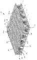
- the spacer fabric 10 has an upper fabric layer 12, a lower fabric layer 14 and a spacer layer 20 arranged therebetween.
- the upper knitted layer 12 is formed as a woven fabric of monofilament base threads 16 into which conductive threads 32a in the warp direction and conductive threads 32b in a weft direction are woven so that they result in a heating loop structure 34 for forming an electrical heating device 30 . Weft and warp directions can also be reversed.
- An electrical contact is formed at the crossing points between the conductive threads 32a, 32b.
- the conductive filaments 32a, 32b are made of a polymeric material which is electrically conductive at ambient temperature and current blocking at a predetermined elevated temperature limit.
- the conductive threads 32 are preferably selected to be the same or largely the same as the non-conductive basic threads 16 of the spacer fabric 10 designed as a three-dimensional fabric in terms of diameter, stretch behavior, strength and/or flexibility.
- the lower knitted fabric layer 14 is also formed as a woven fabric made of non-conductive base threads 16 .
- the upper knitted layer 12 and the lower knitted layer 14 are connected to one another via pile threads 22 of the spacer layer 20 running essentially perpendicular thereto.
- the pile threads 22 can simultaneously serve as ground threads 16 in the upper knitted fabric layer 12 and the lower knitted fabric layer 14 .
- the pile threads 22 are spaced apart from one another in such a way that a free space 24 is formed in the spacer layer 20, through which air can flow, which is shown schematically is indicated by arrows.
- the air flow can be free or forced by a fan device.
- the conductive threads 32 for forming the heating device 30 are incorporated into the fabric of the upper knitted layer 12 . At two contact sections, free end sections of the conductive threads 32 extend downward as pile threads 22 to the lower knitted layer 14 in order to form connections 38 there for an electrical connection to a power source. When current is passed through, due to an internal resistance of the conductive threads 32 of the heating device 30 , heat is generated which can be emitted to the upper side of the spacer fabric 10 . Further conductive threads 32 can preferably also extend as pile threads 22, which are part of the heating device 30, in the region of the spacer layer 20, so that the air flow through the spacer layer 20 can also be heated. This increases the ability of the heated air to absorb moisture. Air flow can also be upward through openings in the woven upper fabric layer 12 .
Landscapes
- Engineering & Computer Science (AREA)
- Aviation & Aerospace Engineering (AREA)
- Transportation (AREA)
- Mechanical Engineering (AREA)
- Textile Engineering (AREA)
- Surface Heating Bodies (AREA)
- Knitting Of Fabric (AREA)
- Chair Legs, Seat Parts, And Backrests (AREA)
Claims (10)
- Maillage de séparation, en particulier pour un coussin d'assise, comportant :- une couche de maillage supérieure (12),- une couche de maillage inférieure (14) qui est sensiblement parallèle à la couche de maillage supérieure (12),- une couche de séparation (20) qui est agencée entre la couche de maillage supérieure (12) et la couche de maillage inférieure (14) et est formée par des fils de poil (22) qui s'étendent sensiblement perpendiculairement à la couche de maillage supérieure (12) et à la couche de maillage inférieure (14) et relient celles-ci, dans lequel les fils de poil (22) sont espacés l'un de l'autre pour la formation d'un espace libre (24) qui peut être traversé par de l'air, et- un dispositif de chauffage (30) au niveau de la couche de maillage supérieure (12), caractérisé en ce quele dispositif de chauffage (30) est formé avec des fils conducteurs (32) en un matériau polymère qui est électroconducteur à température ambiante et est nonconducteur à une température limite élevée prédéfinie,en ce que les fils conducteurs (32) sont insérés dans une structure de fil de la couche de maillage supérieure (12), eten ce qu'au moins une partie des fils de poil (22) est formée par les fils conducteurs (32).
- Maillage de séparation selon la revendication 1,
caractérisé en ce que
les fils conducteurs (32) sont formés en un matériau PTC. - Maillage de séparation selon la revendication 1 ou 2,
caractérisé en ce queau moins la couche de maillage supérieure (12) est réalisée comme une couche de tissu, eten ce que les fils conducteurs (32) sont tissés comme fils de trame et/ou de chaîne conjointement avec des fils de base non-conducteurs (16) en la couche de maillage supérieure (12). - Maillage de séparation selon la revendication 3,
caractérisé en ce que
les fils conducteurs (32) sont tissés dans la couche de maillage supérieure (12) de sorte que ceux-ci soient agencés en méandres dans une zone de chauffage prévue, une structure de boucle de chauffage (34) étant formée. - Maillage de séparation selon la revendication 3 ou 4,
caractérisé en ce que
au moins la couche de maillage supérieure (12) est formée en une seule couche avec une structure poreuse ouverte. - Maillage de séparation selon l'une des revendications 1 à 5,
caractérisé en ce que
les fils conducteurs (32) sont réalisés comme monofils. - Maillage de séparation selon l'une des revendications 1 à 6,
caractérisé en ce que
celui-ci est formé dans l'ensemble comme un tissu en trois dimensions. - Siège, en particulier siège de véhicule, comprenant au moins une partie de siège et une partie de dossier,
caractérisé en ce que
la partie de siège et/ou la partie de dossier présente un maillage de séparation (10) selon l'une des revendications 1 à 7. - Siège selon la revendication 8,
caractérisé en ce que
au moins un système de ventilation est prévu, par lequel un écoulement d'air dans la couche de séparation (20) du maillage de séparation (10) peut être produit. - Siège selon la revendication 8 ou 9,
caractérisé en ce que
des raccordements électriques (38) sont agencés au niveau de la couche de maillage inférieure (14) pour les fils conducteurs (32), au moins deux fils conducteurs (32) s'étendant comme fils de poil (22) de la couche de maillage supérieure (12) à la couche de maillage inférieure (14) et sont reliés aux raccordements électriques (38).
Priority Applications (4)
| Application Number | Priority Date | Filing Date | Title |
|---|---|---|---|
| EP20167888.5A EP3890435B1 (fr) | 2020-04-03 | 2020-04-03 | Maillage de séparation, en particulier pour un coussin d'assise |
| ES20167888T ES2937072T3 (es) | 2020-04-03 | 2020-04-03 | Malla espaciadora, en particular para un acolchado de asiento |
| PL20167888.5T PL3890435T3 (pl) | 2020-04-03 | 2020-04-03 | Tkanina dystansowa, w szczególności dla tapicerki siedziska |
| PCT/EP2021/051729 WO2021197680A1 (fr) | 2020-04-03 | 2021-01-26 | Matériau d'espacement tricoté, en particulier pour un coussin de siège |
Applications Claiming Priority (1)
| Application Number | Priority Date | Filing Date | Title |
|---|---|---|---|
| EP20167888.5A EP3890435B1 (fr) | 2020-04-03 | 2020-04-03 | Maillage de séparation, en particulier pour un coussin d'assise |
Publications (2)
| Publication Number | Publication Date |
|---|---|
| EP3890435A1 EP3890435A1 (fr) | 2021-10-06 |
| EP3890435B1 true EP3890435B1 (fr) | 2022-12-21 |
Family
ID=70165924
Family Applications (1)
| Application Number | Title | Priority Date | Filing Date |
|---|---|---|---|
| EP20167888.5A Active EP3890435B1 (fr) | 2020-04-03 | 2020-04-03 | Maillage de séparation, en particulier pour un coussin d'assise |
Country Status (4)
| Country | Link |
|---|---|
| EP (1) | EP3890435B1 (fr) |
| ES (1) | ES2937072T3 (fr) |
| PL (1) | PL3890435T3 (fr) |
| WO (1) | WO2021197680A1 (fr) |
Citations (2)
| Publication number | Priority date | Publication date | Assignee | Title |
|---|---|---|---|---|
| EP0202896B1 (fr) * | 1985-05-17 | 1991-09-04 | RAYCHEM CORPORATION (a Delaware corporation) | Elément chauffant électrique en forme de feuille |
| DE10013492A1 (de) * | 2000-03-20 | 2001-09-27 | Cetex Chemnitzer Textilmaschin | Fahrzeugsitz |
Family Cites Families (6)
| Publication number | Priority date | Publication date | Assignee | Title |
|---|---|---|---|---|
| DE4239068C2 (de) | 1992-11-20 | 1996-03-14 | Peter Rickerl | Abstandsgewirke zur Aufpolsterung |
| JP2000516484A (ja) | 1995-12-22 | 2000-12-12 | ヘキスト・セラニーズ・コーポレーション | 高度の空気循環を有する乗物シート及びそこで用いられる材料 |
| DE29901225U1 (de) | 1998-01-26 | 1999-05-12 | Mueller Peter | Abstandsgewirke zur Aufpolsterung |
| EP2456282B1 (fr) | 2010-11-18 | 2012-09-12 | Mattes & Ammann GmbH & Co. KG | Maillage à écartement à des fins de chauffage, son procédé de fabrication et son utilisation |
| DE102012012285A1 (de) * | 2012-06-20 | 2012-12-13 | Daimler Ag | Verkleidungselement für einen Innenraum eines Kraftwagens |
| DE102015114778A1 (de) * | 2015-09-03 | 2017-03-09 | Müller Textil GmbH | Abstandsgewirke, Abstandsgewirkeabschnitt sowie beheizbares Verkleidungselement |
-
2020
- 2020-04-03 PL PL20167888.5T patent/PL3890435T3/pl unknown
- 2020-04-03 EP EP20167888.5A patent/EP3890435B1/fr active Active
- 2020-04-03 ES ES20167888T patent/ES2937072T3/es active Active
-
2021
- 2021-01-26 WO PCT/EP2021/051729 patent/WO2021197680A1/fr active Application Filing
Patent Citations (2)
| Publication number | Priority date | Publication date | Assignee | Title |
|---|---|---|---|---|
| EP0202896B1 (fr) * | 1985-05-17 | 1991-09-04 | RAYCHEM CORPORATION (a Delaware corporation) | Elément chauffant électrique en forme de feuille |
| DE10013492A1 (de) * | 2000-03-20 | 2001-09-27 | Cetex Chemnitzer Textilmaschin | Fahrzeugsitz |
Also Published As
| Publication number | Publication date |
|---|---|
| PL3890435T3 (pl) | 2023-03-13 |
| EP3890435A1 (fr) | 2021-10-06 |
| WO2021197680A1 (fr) | 2021-10-07 |
| ES2937072T3 (es) | 2023-03-23 |
Similar Documents
| Publication | Publication Date | Title |
|---|---|---|
| EP1777992B1 (fr) | Elément flexible plat, en particulier pour chauffages de sièges, et le procédé de fabrication d'un élément chauffable flexible | |
| DE102008020391B4 (de) | Heizmatte mit reduziertem Stromverbrauch | |
| DE102006026047B4 (de) | Heizelement, Sitz und Fahrzeug mit einem solchen | |
| EP1961264B1 (fr) | Element chauffant plat | |
| DE4020580A1 (de) | Elektrisches flaechenheizelement | |
| EP0532468B1 (fr) | Elément chauffant électrique | |
| DE10304761B4 (de) | Flexibles Heizelement | |
| EP1851075B1 (fr) | Dispositif de chauffage pour chauffer un flux d'air notamment pour un vehicule automobile | |
| WO2007012477A1 (fr) | Siege de vehicule automobile comprenant un dispositif d'aeration | |
| WO2007048520A2 (fr) | Élément de chauffage plat pour un siège de véhicule à moteur | |
| EP3141646A1 (fr) | Tissu tridimensionnel, section de tissu tridimensionnel et element d'habillage pouvant etre chauffe | |
| WO2007012470A1 (fr) | Siege de vehicule a moteur equipe d'un dispositif d'alimentation en air | |
| EP0991347B1 (fr) | Partie de soutien d'un siege | |
| DE102009013250B3 (de) | Gewirkeabschnitt, insbesondere zur Verwendung als Heizeinlage, sowie Verfahren zur Herstellung eines Gewirkes | |
| DE102018120999B4 (de) | Abstandsgewirke | |
| DE202006011524U1 (de) | Textiles Polflächengebilde | |
| WO1995001082A1 (fr) | Element de chauffage de surface | |
| DE102005035116B3 (de) | Kraftahrzeugsitz mit einer Belüftungseinrichtung | |
| EP3890435B1 (fr) | Maillage de séparation, en particulier pour un coussin d'assise | |
| DE102005035113B4 (de) | Kraftfahrzeugsitz mit einer Luftversorgungseinrichtung | |
| DE10319048A1 (de) | Einlage zur Klimatisierung | |
| DE102008034815A1 (de) | Elektrisches Flächenheizelement sowie Verfahren zur Herstellung eines elektrischen Flächenheizelementes | |
| DE102019103935B4 (de) | Heizeinlage in Form eines Abstandsgewirkeabschnittes sowie beheizbares Interieurbauteil | |
| DE202006004033U1 (de) | Heizgewebe | |
| DE202006008796U1 (de) | Flächiges Heizelement |
Legal Events
| Date | Code | Title | Description |
|---|---|---|---|
| STAA | Information on the status of an ep patent application or granted ep patent |
Free format text: STATUS: EXAMINATION IS IN PROGRESS |
|
| PUAI | Public reference made under article 153(3) epc to a published international application that has entered the european phase |
Free format text: ORIGINAL CODE: 0009012 |
|
| 17P | Request for examination filed |
Effective date: 20201022 |
|
| AK | Designated contracting states |
Kind code of ref document: A1 Designated state(s): AL AT BE BG CH CY CZ DE DK EE ES FI FR GB GR HR HU IE IS IT LI LT LU LV MC MK MT NL NO PL PT RO RS SE SI SK SM TR |
|
| GRAP | Despatch of communication of intention to grant a patent |
Free format text: ORIGINAL CODE: EPIDOSNIGR1 |
|
| STAA | Information on the status of an ep patent application or granted ep patent |
Free format text: STATUS: GRANT OF PATENT IS INTENDED |
|
| INTG | Intention to grant announced |
Effective date: 20220719 |
|
| GRAS | Grant fee paid |
Free format text: ORIGINAL CODE: EPIDOSNIGR3 |
|
| GRAA | (expected) grant |
Free format text: ORIGINAL CODE: 0009210 |
|
| STAA | Information on the status of an ep patent application or granted ep patent |
Free format text: STATUS: THE PATENT HAS BEEN GRANTED |
|
| AK | Designated contracting states |
Kind code of ref document: B1 Designated state(s): AL AT BE BG CH CY CZ DE DK EE ES FI FR GB GR HR HU IE IS IT LI LT LU LV MC MK MT NL NO PL PT RO RS SE SI SK SM TR |
|
| REG | Reference to a national code |
Ref country code: GB Ref legal event code: FG4D Free format text: NOT ENGLISH |
|
| REG | Reference to a national code |
Ref country code: CH Ref legal event code: EP |
|
| REG | Reference to a national code |
Ref country code: DE Ref legal event code: R096 Ref document number: 502020002217 Country of ref document: DE |
|
| REG | Reference to a national code |
Ref country code: AT Ref legal event code: REF Ref document number: 1539832 Country of ref document: AT Kind code of ref document: T Effective date: 20230115 |
|
| REG | Reference to a national code |
Ref country code: IE Ref legal event code: FG4D Free format text: LANGUAGE OF EP DOCUMENT: GERMAN |
|
| REG | Reference to a national code |
Ref country code: RO Ref legal event code: EPE |
|
| REG | Reference to a national code |
Ref country code: ES Ref legal event code: FG2A Ref document number: 2937072 Country of ref document: ES Kind code of ref document: T3 Effective date: 20230323 |
|
| REG | Reference to a national code |
Ref country code: LT Ref legal event code: MG9D |
|
| REG | Reference to a national code |
Ref country code: NL Ref legal event code: MP Effective date: 20221221 |
|
| PG25 | Lapsed in a contracting state [announced via postgrant information from national office to epo] |
Ref country code: SE Free format text: LAPSE BECAUSE OF FAILURE TO SUBMIT A TRANSLATION OF THE DESCRIPTION OR TO PAY THE FEE WITHIN THE PRESCRIBED TIME-LIMIT Effective date: 20221221 Ref country code: NO Free format text: LAPSE BECAUSE OF FAILURE TO SUBMIT A TRANSLATION OF THE DESCRIPTION OR TO PAY THE FEE WITHIN THE PRESCRIBED TIME-LIMIT Effective date: 20230321 Ref country code: LT Free format text: LAPSE BECAUSE OF FAILURE TO SUBMIT A TRANSLATION OF THE DESCRIPTION OR TO PAY THE FEE WITHIN THE PRESCRIBED TIME-LIMIT Effective date: 20221221 Ref country code: FI Free format text: LAPSE BECAUSE OF FAILURE TO SUBMIT A TRANSLATION OF THE DESCRIPTION OR TO PAY THE FEE WITHIN THE PRESCRIBED TIME-LIMIT Effective date: 20221221 |
|
| PG25 | Lapsed in a contracting state [announced via postgrant information from national office to epo] |
Ref country code: RS Free format text: LAPSE BECAUSE OF FAILURE TO SUBMIT A TRANSLATION OF THE DESCRIPTION OR TO PAY THE FEE WITHIN THE PRESCRIBED TIME-LIMIT Effective date: 20221221 Ref country code: LV Free format text: LAPSE BECAUSE OF FAILURE TO SUBMIT A TRANSLATION OF THE DESCRIPTION OR TO PAY THE FEE WITHIN THE PRESCRIBED TIME-LIMIT Effective date: 20221221 Ref country code: HR Free format text: LAPSE BECAUSE OF FAILURE TO SUBMIT A TRANSLATION OF THE DESCRIPTION OR TO PAY THE FEE WITHIN THE PRESCRIBED TIME-LIMIT Effective date: 20221221 Ref country code: GR Free format text: LAPSE BECAUSE OF FAILURE TO SUBMIT A TRANSLATION OF THE DESCRIPTION OR TO PAY THE FEE WITHIN THE PRESCRIBED TIME-LIMIT Effective date: 20230322 |
|
| PGFP | Annual fee paid to national office [announced via postgrant information from national office to epo] |
Ref country code: TR Payment date: 20230330 Year of fee payment: 4 Ref country code: PL Payment date: 20230324 Year of fee payment: 4 |
|
| P01 | Opt-out of the competence of the unified patent court (upc) registered |
Effective date: 20230427 |
|
| PG25 | Lapsed in a contracting state [announced via postgrant information from national office to epo] |
Ref country code: NL Free format text: LAPSE BECAUSE OF FAILURE TO SUBMIT A TRANSLATION OF THE DESCRIPTION OR TO PAY THE FEE WITHIN THE PRESCRIBED TIME-LIMIT Effective date: 20221221 |
|
| PG25 | Lapsed in a contracting state [announced via postgrant information from national office to epo] |
Ref country code: SM Free format text: LAPSE BECAUSE OF FAILURE TO SUBMIT A TRANSLATION OF THE DESCRIPTION OR TO PAY THE FEE WITHIN THE PRESCRIBED TIME-LIMIT Effective date: 20221221 Ref country code: PT Free format text: LAPSE BECAUSE OF FAILURE TO SUBMIT A TRANSLATION OF THE DESCRIPTION OR TO PAY THE FEE WITHIN THE PRESCRIBED TIME-LIMIT Effective date: 20230421 Ref country code: EE Free format text: LAPSE BECAUSE OF FAILURE TO SUBMIT A TRANSLATION OF THE DESCRIPTION OR TO PAY THE FEE WITHIN THE PRESCRIBED TIME-LIMIT Effective date: 20221221 Ref country code: CZ Free format text: LAPSE BECAUSE OF FAILURE TO SUBMIT A TRANSLATION OF THE DESCRIPTION OR TO PAY THE FEE WITHIN THE PRESCRIBED TIME-LIMIT Effective date: 20221221 |
|
| PGFP | Annual fee paid to national office [announced via postgrant information from national office to epo] |
Ref country code: IE Payment date: 20230425 Year of fee payment: 4 Ref country code: FR Payment date: 20230417 Year of fee payment: 4 Ref country code: ES Payment date: 20230517 Year of fee payment: 4 Ref country code: DE Payment date: 20230426 Year of fee payment: 4 Ref country code: CH Payment date: 20230502 Year of fee payment: 4 |
|
| PG25 | Lapsed in a contracting state [announced via postgrant information from national office to epo] |
Ref country code: SK Free format text: LAPSE BECAUSE OF FAILURE TO SUBMIT A TRANSLATION OF THE DESCRIPTION OR TO PAY THE FEE WITHIN THE PRESCRIBED TIME-LIMIT Effective date: 20221221 Ref country code: IS Free format text: LAPSE BECAUSE OF FAILURE TO SUBMIT A TRANSLATION OF THE DESCRIPTION OR TO PAY THE FEE WITHIN THE PRESCRIBED TIME-LIMIT Effective date: 20230421 Ref country code: AL Free format text: LAPSE BECAUSE OF FAILURE TO SUBMIT A TRANSLATION OF THE DESCRIPTION OR TO PAY THE FEE WITHIN THE PRESCRIBED TIME-LIMIT Effective date: 20221221 |
|
| REG | Reference to a national code |
Ref country code: DE Ref legal event code: R097 Ref document number: 502020002217 Country of ref document: DE |
|
| PGFP | Annual fee paid to national office [announced via postgrant information from national office to epo] |
Ref country code: BE Payment date: 20230417 Year of fee payment: 4 |
|
| PLBE | No opposition filed within time limit |
Free format text: ORIGINAL CODE: 0009261 |
|
| STAA | Information on the status of an ep patent application or granted ep patent |
Free format text: STATUS: NO OPPOSITION FILED WITHIN TIME LIMIT |
|
| PG25 | Lapsed in a contracting state [announced via postgrant information from national office to epo] |
Ref country code: DK Free format text: LAPSE BECAUSE OF FAILURE TO SUBMIT A TRANSLATION OF THE DESCRIPTION OR TO PAY THE FEE WITHIN THE PRESCRIBED TIME-LIMIT Effective date: 20221221 |
|
| 26N | No opposition filed |
Effective date: 20230922 |
|
| PG25 | Lapsed in a contracting state [announced via postgrant information from national office to epo] |
Ref country code: MC Free format text: LAPSE BECAUSE OF FAILURE TO SUBMIT A TRANSLATION OF THE DESCRIPTION OR TO PAY THE FEE WITHIN THE PRESCRIBED TIME-LIMIT Effective date: 20221221 |
|
| PG25 | Lapsed in a contracting state [announced via postgrant information from national office to epo] |
Ref country code: SI Free format text: LAPSE BECAUSE OF FAILURE TO SUBMIT A TRANSLATION OF THE DESCRIPTION OR TO PAY THE FEE WITHIN THE PRESCRIBED TIME-LIMIT Effective date: 20221221 Ref country code: MC Free format text: LAPSE BECAUSE OF FAILURE TO SUBMIT A TRANSLATION OF THE DESCRIPTION OR TO PAY THE FEE WITHIN THE PRESCRIBED TIME-LIMIT Effective date: 20221221 |
|
| PGFP | Annual fee paid to national office [announced via postgrant information from national office to epo] |
Ref country code: RO Payment date: 20240326 Year of fee payment: 5 |
|
| PGFP | Annual fee paid to national office [announced via postgrant information from national office to epo] |
Ref country code: LU Payment date: 20240418 Year of fee payment: 5 |