EP3889484B1 - Fluidische einheit und verfahren zum herstellen einer fluidischen einheit - Google Patents
Fluidische einheit und verfahren zum herstellen einer fluidischen einheit Download PDFInfo
- Publication number
- EP3889484B1 EP3889484B1 EP21000092.3A EP21000092A EP3889484B1 EP 3889484 B1 EP3889484 B1 EP 3889484B1 EP 21000092 A EP21000092 A EP 21000092A EP 3889484 B1 EP3889484 B1 EP 3889484B1
- Authority
- EP
- European Patent Office
- Prior art keywords
- profile
- plug
- outside diameter
- corrugated pipe
- section
- Prior art date
- Legal status (The legal status is an assumption and is not a legal conclusion. Google has not performed a legal analysis and makes no representation as to the accuracy of the status listed.)
- Active
Links
Images

Classifications
-
- F—MECHANICAL ENGINEERING; LIGHTING; HEATING; WEAPONS; BLASTING
- F16—ENGINEERING ELEMENTS AND UNITS; GENERAL MEASURES FOR PRODUCING AND MAINTAINING EFFECTIVE FUNCTIONING OF MACHINES OR INSTALLATIONS; THERMAL INSULATION IN GENERAL
- F16L—PIPES; JOINTS OR FITTINGS FOR PIPES; SUPPORTS FOR PIPES, CABLES OR PROTECTIVE TUBING; MEANS FOR THERMAL INSULATION IN GENERAL
- F16L11/00—Hoses, i.e. flexible pipes
- F16L11/14—Hoses, i.e. flexible pipes made of rigid material, e.g. metal or hard plastics
- F16L11/15—Hoses, i.e. flexible pipes made of rigid material, e.g. metal or hard plastics corrugated
-
- B—PERFORMING OPERATIONS; TRANSPORTING
- B60—VEHICLES IN GENERAL
- B60K—ARRANGEMENT OR MOUNTING OF PROPULSION UNITS OR OF TRANSMISSIONS IN VEHICLES; ARRANGEMENT OR MOUNTING OF PLURAL DIVERSE PRIME-MOVERS IN VEHICLES; AUXILIARY DRIVES FOR VEHICLES; INSTRUMENTATION OR DASHBOARDS FOR VEHICLES; ARRANGEMENTS IN CONNECTION WITH COOLING, AIR INTAKE, GAS EXHAUST OR FUEL SUPPLY OF PROPULSION UNITS IN VEHICLES
- B60K1/00—Arrangement or mounting of electrical propulsion units
-
- B—PERFORMING OPERATIONS; TRANSPORTING
- B29—WORKING OF PLASTICS; WORKING OF SUBSTANCES IN A PLASTIC STATE IN GENERAL
- B29C—SHAPING OR JOINING OF PLASTICS; SHAPING OF MATERIAL IN A PLASTIC STATE, NOT OTHERWISE PROVIDED FOR; AFTER-TREATMENT OF THE SHAPED PRODUCTS, e.g. REPAIRING
- B29C48/00—Extrusion moulding, i.e. expressing the moulding material through a die or nozzle which imparts the desired form; Apparatus therefor
- B29C48/03—Extrusion moulding, i.e. expressing the moulding material through a die or nozzle which imparts the desired form; Apparatus therefor characterised by the shape of the extruded material at extrusion
- B29C48/09—Articles with cross-sections having partially or fully enclosed cavities, e.g. pipes or channels
-
- B—PERFORMING OPERATIONS; TRANSPORTING
- B29—WORKING OF PLASTICS; WORKING OF SUBSTANCES IN A PLASTIC STATE IN GENERAL
- B29C—SHAPING OR JOINING OF PLASTICS; SHAPING OF MATERIAL IN A PLASTIC STATE, NOT OTHERWISE PROVIDED FOR; AFTER-TREATMENT OF THE SHAPED PRODUCTS, e.g. REPAIRING
- B29C48/00—Extrusion moulding, i.e. expressing the moulding material through a die or nozzle which imparts the desired form; Apparatus therefor
- B29C48/03—Extrusion moulding, i.e. expressing the moulding material through a die or nozzle which imparts the desired form; Apparatus therefor characterised by the shape of the extruded material at extrusion
- B29C48/13—Articles with a cross-section varying in the longitudinal direction, e.g. corrugated pipes
-
- B—PERFORMING OPERATIONS; TRANSPORTING
- B29—WORKING OF PLASTICS; WORKING OF SUBSTANCES IN A PLASTIC STATE IN GENERAL
- B29C—SHAPING OR JOINING OF PLASTICS; SHAPING OF MATERIAL IN A PLASTIC STATE, NOT OTHERWISE PROVIDED FOR; AFTER-TREATMENT OF THE SHAPED PRODUCTS, e.g. REPAIRING
- B29C48/00—Extrusion moulding, i.e. expressing the moulding material through a die or nozzle which imparts the desired form; Apparatus therefor
- B29C48/25—Component parts, details or accessories; Auxiliary operations
- B29C48/30—Extrusion nozzles or dies
- B29C48/303—Extrusion nozzles or dies using dies or die parts movable in a closed circuit, e.g. mounted on movable endless support
-
- B—PERFORMING OPERATIONS; TRANSPORTING
- B29—WORKING OF PLASTICS; WORKING OF SUBSTANCES IN A PLASTIC STATE IN GENERAL
- B29C—SHAPING OR JOINING OF PLASTICS; SHAPING OF MATERIAL IN A PLASTIC STATE, NOT OTHERWISE PROVIDED FOR; AFTER-TREATMENT OF THE SHAPED PRODUCTS, e.g. REPAIRING
- B29C48/00—Extrusion moulding, i.e. expressing the moulding material through a die or nozzle which imparts the desired form; Apparatus therefor
- B29C48/25—Component parts, details or accessories; Auxiliary operations
- B29C48/30—Extrusion nozzles or dies
- B29C48/32—Extrusion nozzles or dies with annular openings, e.g. for forming tubular articles
-
- B—PERFORMING OPERATIONS; TRANSPORTING
- B60—VEHICLES IN GENERAL
- B60L—PROPULSION OF ELECTRICALLY-PROPELLED VEHICLES; SUPPLYING ELECTRIC POWER FOR AUXILIARY EQUIPMENT OF ELECTRICALLY-PROPELLED VEHICLES; ELECTRODYNAMIC BRAKE SYSTEMS FOR VEHICLES IN GENERAL; MAGNETIC SUSPENSION OR LEVITATION FOR VEHICLES; MONITORING OPERATING VARIABLES OF ELECTRICALLY-PROPELLED VEHICLES; ELECTRIC SAFETY DEVICES FOR ELECTRICALLY-PROPELLED VEHICLES
- B60L58/00—Methods or circuit arrangements for monitoring or controlling batteries or fuel cells, specially adapted for electric vehicles
- B60L58/10—Methods or circuit arrangements for monitoring or controlling batteries or fuel cells, specially adapted for electric vehicles for monitoring or controlling batteries
- B60L58/24—Methods or circuit arrangements for monitoring or controlling batteries or fuel cells, specially adapted for electric vehicles for monitoring or controlling batteries for controlling the temperature of batteries
- B60L58/26—Methods or circuit arrangements for monitoring or controlling batteries or fuel cells, specially adapted for electric vehicles for monitoring or controlling batteries for controlling the temperature of batteries by cooling
-
- F—MECHANICAL ENGINEERING; LIGHTING; HEATING; WEAPONS; BLASTING
- F16—ENGINEERING ELEMENTS AND UNITS; GENERAL MEASURES FOR PRODUCING AND MAINTAINING EFFECTIVE FUNCTIONING OF MACHINES OR INSTALLATIONS; THERMAL INSULATION IN GENERAL
- F16L—PIPES; JOINTS OR FITTINGS FOR PIPES; SUPPORTS FOR PIPES, CABLES OR PROTECTIVE TUBING; MEANS FOR THERMAL INSULATION IN GENERAL
- F16L11/00—Hoses, i.e. flexible pipes
- F16L11/04—Hoses, i.e. flexible pipes made of rubber or flexible plastics
- F16L11/11—Hoses, i.e. flexible pipes made of rubber or flexible plastics with corrugated wall
- F16L11/111—Hoses, i.e. flexible pipes made of rubber or flexible plastics with corrugated wall with homogeneous wall
-
- F—MECHANICAL ENGINEERING; LIGHTING; HEATING; WEAPONS; BLASTING
- F16—ENGINEERING ELEMENTS AND UNITS; GENERAL MEASURES FOR PRODUCING AND MAINTAINING EFFECTIVE FUNCTIONING OF MACHINES OR INSTALLATIONS; THERMAL INSULATION IN GENERAL
- F16L—PIPES; JOINTS OR FITTINGS FOR PIPES; SUPPORTS FOR PIPES, CABLES OR PROTECTIVE TUBING; MEANS FOR THERMAL INSULATION IN GENERAL
- F16L25/00—Construction or details of pipe joints not provided for in, or of interest apart from, groups F16L13/00 - F16L23/00
- F16L25/0036—Joints for corrugated pipes
-
- F—MECHANICAL ENGINEERING; LIGHTING; HEATING; WEAPONS; BLASTING
- F16—ENGINEERING ELEMENTS AND UNITS; GENERAL MEASURES FOR PRODUCING AND MAINTAINING EFFECTIVE FUNCTIONING OF MACHINES OR INSTALLATIONS; THERMAL INSULATION IN GENERAL
- F16L—PIPES; JOINTS OR FITTINGS FOR PIPES; SUPPORTS FOR PIPES, CABLES OR PROTECTIVE TUBING; MEANS FOR THERMAL INSULATION IN GENERAL
- F16L35/00—Special arrangements used in connection with end fittings of hoses, e.g. safety or protecting devices
-
- F—MECHANICAL ENGINEERING; LIGHTING; HEATING; WEAPONS; BLASTING
- F16—ENGINEERING ELEMENTS AND UNITS; GENERAL MEASURES FOR PRODUCING AND MAINTAINING EFFECTIVE FUNCTIONING OF MACHINES OR INSTALLATIONS; THERMAL INSULATION IN GENERAL
- F16L—PIPES; JOINTS OR FITTINGS FOR PIPES; SUPPORTS FOR PIPES, CABLES OR PROTECTIVE TUBING; MEANS FOR THERMAL INSULATION IN GENERAL
- F16L47/00—Connecting arrangements or other fittings specially adapted to be made of plastics or to be used with pipes made of plastics
-
- H—ELECTRICITY
- H01—ELECTRIC ELEMENTS
- H01M—PROCESSES OR MEANS, e.g. BATTERIES, FOR THE DIRECT CONVERSION OF CHEMICAL ENERGY INTO ELECTRICAL ENERGY
- H01M10/00—Secondary cells; Manufacture thereof
- H01M10/60—Heating or cooling; Temperature control
- H01M10/61—Types of temperature control
- H01M10/613—Cooling or keeping cold
-
- H—ELECTRICITY
- H01—ELECTRIC ELEMENTS
- H01M—PROCESSES OR MEANS, e.g. BATTERIES, FOR THE DIRECT CONVERSION OF CHEMICAL ENERGY INTO ELECTRICAL ENERGY
- H01M10/00—Secondary cells; Manufacture thereof
- H01M10/60—Heating or cooling; Temperature control
- H01M10/62—Heating or cooling; Temperature control specially adapted for specific applications
- H01M10/625—Vehicles
-
- H—ELECTRICITY
- H01—ELECTRIC ELEMENTS
- H01M—PROCESSES OR MEANS, e.g. BATTERIES, FOR THE DIRECT CONVERSION OF CHEMICAL ENERGY INTO ELECTRICAL ENERGY
- H01M10/00—Secondary cells; Manufacture thereof
- H01M10/60—Heating or cooling; Temperature control
- H01M10/65—Means for temperature control structurally associated with the cells
- H01M10/655—Solid structures for heat exchange or heat conduction
- H01M10/6556—Solid parts with flow channel passages or pipes for heat exchange
-
- B—PERFORMING OPERATIONS; TRANSPORTING
- B60—VEHICLES IN GENERAL
- B60K—ARRANGEMENT OR MOUNTING OF PROPULSION UNITS OR OF TRANSMISSIONS IN VEHICLES; ARRANGEMENT OR MOUNTING OF PLURAL DIVERSE PRIME-MOVERS IN VEHICLES; AUXILIARY DRIVES FOR VEHICLES; INSTRUMENTATION OR DASHBOARDS FOR VEHICLES; ARRANGEMENTS IN CONNECTION WITH COOLING, AIR INTAKE, GAS EXHAUST OR FUEL SUPPLY OF PROPULSION UNITS IN VEHICLES
- B60K1/00—Arrangement or mounting of electrical propulsion units
- B60K2001/003—Arrangement or mounting of electrical propulsion units with means for cooling the electrical propulsion units
- B60K2001/005—Arrangement or mounting of electrical propulsion units with means for cooling the electrical propulsion units the electric storage means
-
- F—MECHANICAL ENGINEERING; LIGHTING; HEATING; WEAPONS; BLASTING
- F16—ENGINEERING ELEMENTS AND UNITS; GENERAL MEASURES FOR PRODUCING AND MAINTAINING EFFECTIVE FUNCTIONING OF MACHINES OR INSTALLATIONS; THERMAL INSULATION IN GENERAL
- F16L—PIPES; JOINTS OR FITTINGS FOR PIPES; SUPPORTS FOR PIPES, CABLES OR PROTECTIVE TUBING; MEANS FOR THERMAL INSULATION IN GENERAL
- F16L25/00—Construction or details of pipe joints not provided for in, or of interest apart from, groups F16L13/00 - F16L23/00
- F16L25/0036—Joints for corrugated pipes
- F16L25/0045—Joints for corrugated pipes of the quick-acting type
-
- Y—GENERAL TAGGING OF NEW TECHNOLOGICAL DEVELOPMENTS; GENERAL TAGGING OF CROSS-SECTIONAL TECHNOLOGIES SPANNING OVER SEVERAL SECTIONS OF THE IPC; TECHNICAL SUBJECTS COVERED BY FORMER USPC CROSS-REFERENCE ART COLLECTIONS [XRACs] AND DIGESTS
- Y02—TECHNOLOGIES OR APPLICATIONS FOR MITIGATION OR ADAPTATION AGAINST CLIMATE CHANGE
- Y02E—REDUCTION OF GREENHOUSE GAS [GHG] EMISSIONS, RELATED TO ENERGY GENERATION, TRANSMISSION OR DISTRIBUTION
- Y02E60/00—Enabling technologies; Technologies with a potential or indirect contribution to GHG emissions mitigation
- Y02E60/10—Energy storage using batteries
-
- Y—GENERAL TAGGING OF NEW TECHNOLOGICAL DEVELOPMENTS; GENERAL TAGGING OF CROSS-SECTIONAL TECHNOLOGIES SPANNING OVER SEVERAL SECTIONS OF THE IPC; TECHNICAL SUBJECTS COVERED BY FORMER USPC CROSS-REFERENCE ART COLLECTIONS [XRACs] AND DIGESTS
- Y02—TECHNOLOGIES OR APPLICATIONS FOR MITIGATION OR ADAPTATION AGAINST CLIMATE CHANGE
- Y02T—CLIMATE CHANGE MITIGATION TECHNOLOGIES RELATED TO TRANSPORTATION
- Y02T10/00—Road transport of goods or passengers
- Y02T10/60—Other road transportation technologies with climate change mitigation effect
- Y02T10/70—Energy storage systems for electromobility, e.g. batteries
Definitions
- Connectors and at least one corrugated pipe as well as a method for producing such a fluidic unit.
- Both corrugated pipes and connectors for connecting at least two components, such as two media lines or a media line with an aggregate are known in the state of the art in a wide variety of design variants.
- a connector is manufactured, for example, as an injection-molded component. It can be designed as both a plug part and a socket part.
- a plug part arranged at the end of a media line or an aggregate is inserted, for example, into a socket part arranged at the end of another media line or an aggregate. In order to secure the plug part in the socket part, it is also known to provide at least one holding element.
- Holding elements are also known in a wide variety of designs, for example from WO 2018/019421 A1 .
- the plug connector in particular in the form of a plug part, has at least one receiving section.
- the holding element attached there serves to releasably hold the plug part in the socket part.
- the holding element is also known to design the holding element to be radially expandable in at least one section, wherein at least one holding arm of the holding element is provided with at least one locking lug projecting outwards, the at least one holding arm has a free end and an end fixed to the holding element body and is spring-elastically movable in the radial direction with respect to the plug part for locking the at least one locking lug on at least one locking surface or a locking opening of the socket part and for releasing it.
- the drain hose which is designed as a corrugated hose, is manufactured using a blow molding process. This manufacturing process makes it possible to equip the connection area with two circumferential grooves that can accommodate an O-ring for sealing and a locking washer for fastening.
- connection area designed as a connection sleeve When the connection area designed as a connection sleeve is plugged in, the clamp-like locking washer engages with its inner leg areas in one of the circumferential grooves arranged on the connection sleeve.
- Corrugated pipes serve, for example, as an outer covering for the thermal insulation of a hose- or tubular media line, whereby the air in the space between the outside of the media line and the inside of the corrugated pipe serves to thermally insulate the medium flowing through the media line.
- a corrugated pipe can be attached to an external insulating casing of a connector, for example by means of a form-fitting or material-fitting connection. It is also known to connect such a corrugated pipe directly to a connector, for example by means of a mandrel connection or a welded connection. After the connector and corrugated pipe are connected, a fluidic unit is created.
- the fluidic unit made up of a corrugated pipe and the connector connected to it, in particular in the form of a plug part, can be attached to an aggregate, such as battery cooling plates of a vehicle battery, in particular to its inlet or outlet nozzles, by plugging it on.
- an interface or connection point namely in the form of a mandrel connection or a welded connection, is provided between the connector and the corrugated pipe and/or a media line surrounded by it, as this must meet the high requirements in the automotive sector.
- the costs for producing injection-molded components in the form of connectors and their assembly on a respective corrugated pipe or media line are comparatively high.
- the present invention is therefore based on the object of creating a fluidic unit comprising at least one corrugated pipe and at least one connector, as well as a method for producing such a fluidic unit, in which the number of interfaces between the connector and the corrugated pipe is significantly reduced, thus reducing the manufacturing costs and yet ensuring a high quality of the fluidic unit produced.
- the at least one connector profile section is a connector part profile section and has at least one receiving section for arranging a holding element and at least one groove section for arranging a sealing element, and adjacent to the receiving section a transition section is provided, to which the corrugated pipe profile section adjoins, wherein the corrugated pipe and connector in the form of the connector part profile section are formed in one piece by extrusion in an extrusion device, a holding element and a sealing ring are attached to the connector part profile section(s) arranged at the end of the respective corrugated pipe profile section, the connector part profile section has an end section with an outer diameter, an adjoining bead section with an outer diameter that protrudes slightly from the end section, and adjacent to this the groove section, the outer diameter of which is significantly smaller than the outer diameter of the bead section and the outer diameter of the end section, adjacent to the groove section the connector part profile section has a section that has an outer diameter that approximately corresponds to the outer diameter of the bead
- an endless tube is formed by extrusion, which has sections with a corrugated tube profile and at least one section with two connector profile sections that are mirror images of each other, that the endless tube is demolded, and that the endless tube in the area of the at least one section with the two connector profile sections formed as mirror images of each other between them in at least two fluidic units each having at least one corrugated pipe profile section and at least one connector profile section integrally formed thereon at the end.
- the fluidic unit is created, which comprises at least one corrugated pipe profile section instead of a separate corrugated pipe and at least one plug connection profile section instead of a separate connector.
- the connector profile section is designed as a plug part profile section to be inserted into a socket part as a counterpart, e.g. on another
- the one-piece formation of corrugated pipe and connector, in the form of a connector part profile section, takes place by extrusion in an extrusion device.
- Such an extrusion device for carrying out the method is advantageously designed as a corrugator and has at least two profile inserts in the axial direction of the extrusion device for forming at least two corrugated profile sections and at least one jaw insert with an internal profiling corresponding to two connector profile sections arranged in mirror image to one another.
- the at least one jaw insert can be arranged or is arranged in the axial direction between the at least two profile inserts for forming the at least two corrugated profile sections.
- the at least one jaw insert and the profile inserts are each at least two-part and the respective at least two parts are designed to be separable from one another in the radial direction for demolding an extruded endless pipe.
- an extrusion device designed as a corrugator the extruded plastic material is attracted to the inner profile of the profile inserts by means of suction molds, i.e. by means of negative pressure, and also to the inner profile in the area of the jaw inserts.
- the plastic material is thereby attached to the respective inner profile of the profile inserts and jaw inserts, so that the desired external shape of the corrugated pipe and connector profile sections is obtained.
- the extrusion device thus comprises profile inserts for forming corrugated profile sections.
- the at least one jaw insert is used to form the two connector profile sections arranged in mirror images of one another. These two connector profile sections are subsequently separated from one another.
- the endless pipe can thus comprise several sections with a corrugated pipe profile and several sections with the two connector profiles arranged in mirror images of one another or at least one connector profile section.
- jaw inserts for producing at least one or two connector profile sections arranged in mirror image to one another can be provided in the extrusion device at predeterminable intervals, which can be different in each case, adjacent to profile inserts for shaping corrugated profile sections.
- the jaw inserts with an internal profile corresponding to the connector profile sections are advantageously formed in at least two parts and can be separated radially from one another in order to easily enable the endless pipe produced to be demolded along its longitudinal extent or along its length. Accordingly, two parts of a jaw insert can be provided over the circumference of the endless pipe or connector profile section to be produced, or more than two parts of a jaw insert. For example, two parts of a jaw insert can be provided at an angle of 180°, or three parts or segments of a jaw insert at an angle of 120°, or four parts or segments of a jaw insert at an angle of 90° each. It is also possible to provide an uneven distribution of parts or segments of a jaw insert over the circumference of the connector profile section(s) to be produced. The same applies to the profile inserts for producing the wave profile section(s) of the fluidic unit or, previously, the endless pipe to be formed.
- the at least one connector profile section free of undercuts in relation to the opening direction. If the profile or the geometry of the Since the connector profile section has no undercut, it can be easily demolded in the opening direction of the extrusion device.
- the at least one plug connector profile section has at least one receiving section for arranging a holding element.
- the plug connector profile section also has at least one groove for arranging a sealing element, in particular an O-ring.
- the receiving section for arranging a holding element has an outer diameter that is reduced compared to its adjacent sections on both sides.
- the receiving section can be designed to be uniformly smooth throughout on the outside. It is also possible to provide, in particular, ring-shaped elevations at intervals, such as a type of corrugation, in order to enable a better hold of the holding element on the outside of the receiving section. By reducing the outer diameter in the area of the receiving section, holding arms of the holding element can engage there and be supported in the receiving section.
- the receiving section can have at least one device that enables anti-twisting for arranging a holding element.
- the receiving section can have an irregularly shaped and/or flattened and/or polygonal area that serves as an anti-twisting device.
- a polygonal or at least one-sided flattened design of at least one area of the receiving section is particularly suitable here.
- the holding element is advantageously provided on its inside with a correspondingly shaped, i.e. in particular flattened or polygonal, shape, so that surfaces on the inside of the holding element can rest on corresponding external surfaces of the receiving section, i.e. in particular a polygonal or flattened area thereof. This can create the desired anti-twisting.
- the receiving section for arranging a holding element can be or is provided with at least one pressure locking device which cooperates with the holding element and which enables unlocking of the holding element when pressure is present inside the fluidic unit.
- a pressure locking device can, for example, comprise at least one element protruding from the outside of the receiving section of the plug connector profile section.
- this can be designed in the shape of a pin or as a protruding element, such as a point-shaped elevation.
- the holding element also advantageously comprises at least one opening, which is arranged in particular in at least one of the holding arms of the holding element.
- the plug connector profile section is designed, for example, as a plug part profile section and is inserted into a socket part, it is important to hold the plug part profile section of the fluidic unit and a socket part of another media line or unit securely together, especially when there is pressure inside the fluidic unit, for example due to pressurized medium flowing through there.
- the holding element is plugged onto the receiving section of the plug part profile element, the holding element is advantageously locked and held in place by the pressure locking device, in particular the one or more elements projecting on the outside of the receiving section, when there is media pressure inside the fluidic unit. Applying pressure to the fluidic unit causes an axial relative movement between the holding element and the plug part profile section.
- the plug part profile section or the fluidic unit moves axially in the opposite direction of insertion, i.e. against the direction of insertion of the plug part profile section, out of the socket part, while the holding element is fixed axially immovably in the socket part, for example.
- the projecting element on the outside of the receiving section of the plug part profile section lies outside the corresponding opening in the holding element due to the displacement of the holding element relative to the plug part profile element in the axial direction of the fluidic unit. This can block radial movement of the holding arm(s) of the holding element.
- the holding arms of the holding element are not located in a release position when the at least one projecting element on the outside of the receiving section of the plug part is located outside the opening in the holding element. Due to the axial displacement between the fluidic unit and the holding element, the projecting elements on the outside of the receiving section of the plug part are displaced out of the area of the opening or openings in the holding element and thus radially lock the holding arms of the holding element.
- the fluidic unit advantageously consists of an extrudable material, such as at least one polymer material.
- it can consist of polyamide, such as PA12, or polypropylene.
- These materials enable sufficient stability of the at least one corrugated pipe profile section on the one hand, and sufficient stability of the at least one connector profile section on the other.
- the fluidic unit is particularly suitable for use in the thermal management of a vehicle, such as in the area of modules for cooling a vehicle battery.
- the at least one connector profile section is designed in particular as a connector part profile section and provided with the holding element, so that a fluidic connection with inlets and outlets, i.e.
- inlet nozzles and outlet nozzles, on modules for battery cooling, such as battery cooling plates can be provided by plugging the connector part profile section and the inlet nozzles and outlet nozzles designed accordingly as a sleeve part.
- the fluidic unit provided with the connector profile section at at least one end is advantageously first provided with the holding element and subsequently with the at least one sealing element, for example an O-ring.
- a plug connection can then be made directly, for example with a socket part, such as an inlet nozzle or an outlet nozzle on a module for battery cooling of a vehicle battery. This also makes it easy to assemble numerous fluidic units on a large number of modules for battery cooling in a vehicle, which are provided with inlets and outlets, in just a few steps.
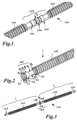
- Figure 1 is a perspective view of a detail of an endless pipe 100 with two corrugated pipe profile sections 101, 102 and a between these arranged section 103 and two connector profile sections 104, 105, which are mirror images of each other and connected to each other.
- the two connector profile sections 104, 105 merge into each other. They have the shape of connector part profile sections.
- the endless pipe with its corrugated pipe profile sections 101, 102 and the two connector profile sections 104, 105 is designed as one part, i.e. in one piece.
- the endless pipe 100 is separated in the respective sections 103 between two connector profile sections 104, 105. This is indicated by an arrow P1 pointing to a separation point 106 in Figure 1 indicated.
- Figure 2 shows the resulting fluidic unit 1 with the corrugated pipe profile section 102 and the connector profile section 105 integrally formed on the end. This is in the design according to Figure 2 designed as a plug part profile section.
- the plug part profile section 105 has an end section 20 with an outer diameter d 1 , an adjoining bead section 21 with an outer diameter d 2 that projects slightly relative to the end section 20, and following this a groove section 22 whose outer diameter d 3 is significantly smaller than the outer diameter d 2 of the bead section 21 and also than the outer diameter d 1 of the end section 20.
- Adjacent to the groove section 22, the plug part profile section 105 has a section 23 that has an outer diameter d 4 that corresponds approximately to the outer diameter d 2 of the bead section 21, and a receiving section 24 with an outer diameter d 5 that corresponds approximately to the outer diameter d 3 of the groove section 22.
- a transition section 25 Adjacent to the receiving section 24, a transition section 25 is provided, to which the corrugated pipe profile section 102 is connected.
- the transition section 25 has an outer diameter d 6 which corresponds approximately to the outer diameter d 4 or d 2 of the section 23 and the bead section 21.
- FIG 3 two fluidic units 1 are shown, each with connector profile sections 104 and 105 at the end and the section 103 not yet separated into two connector profile sections 2.
- an endless tube 100 with any number of corrugated tube profile sections 101, 102 with connector profile sections arranged in between or connector profile sections 104 and 105 formed at both ends of the endless tube 100, just one or two corrugated tube profile sections with connector profile sections integrally formed on the end can be provided.
- the length of the respective corrugated tube profile sections 101 and 102 and also of the connector profile sections 104, 105 arranged in between can be varied depending on the application.
- the corrugated pipe profile sections 101 and 102 it is possible to design the corrugated pipe profile sections 101 and 102 to have different lengths in order to produce fluidic units 1 of different lengths, each of which is provided at least at one end with the connector profile section 104 or 105.
- the other end of the corrugated pipe profile section 101 or 102 can also be designed without a connector profile section, so that a separately manufactured connector, for example in the form of a separately manufactured sleeve part, can be pierced, welded or otherwise fastened to such an end.
- An extrusion device 200 also referred to as a corrugator, is used to produce such an endless tube 100.
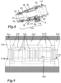
- Such an extrusion device 200 is described in Figure 9 a section is shown.
- two profile inserts 201, 202 are shown with a jaw insert 203 arranged between them.
- the two profile inserts 201, 202 serve to shape the corrugated profile of the corrugated pipe profile sections 101, 102, while the jaw insert 203 corresponds to the outer profile of the connector profile sections 104, 105 with regard to its inner profile 204.
- two parts or segments 205, 206 of the jaw insert 203 can be arranged in the circumferential direction of the endless pipe 100 to be produced.
- the two-part jaw insert 203 is in Figure 4 , whereby the opening device for removal is indicated by the double arrow P2.
- the longitudinal section through the two parts 205, 206 of the jaw insert 203 in Figure 4 is at the level of the profiling for forming one of the two groove sections 22 of the later connector profile section 104 or 105.
- negative pressure acting on this serves, which acts in the direction of the inside of the jaw insert 203 or the profile inserts 201, 202.
- the plastic material is sucked into the inner profiling via suction openings 207 and grooves 208 arranged in the area of the inner profiling 204.
- the jaw insert 203 can be easily inserted into a corrugator chain, i.e. between two profile inserts 201, 202 for forming corrugated pipe profile sections 101, 102. This enables easy integration of jaw inserts 203 into an extrusion device, such as the extrusion device 200, for forming endless pipes 100 and, subsequently, fluidic units 1.
- the connector profile section(s) or connector part profile section(s) 104, 105 arranged at the end of the respective corrugated pipe profile section 101, 102 can be fitted with, as shown in the sequence of assembly steps in Figure 5 to Figure 7 shown, a holding element 3 and a sealing ring, here in the form of an O-ring 4, are attached.
- the direction of sliding on the holding element 3 and the O-ring 4 is shown in Figure 6 indicated by an arrow P3.
- the holding element 3 and subsequently the O-ring 4 are pushed onto the end of the plug part profile element in the direction of the arrow P3, i.e. firstly its end section 20, then the bead section 21 is pushed away for positioning in the groove section 22.
- the holding element 3 After assembly on the plug part profile section 105, the holding element 3 is essentially pushed onto its receiving section 24 positioned. This can also Figure 8 can be removed. At the end, the holding element 3 is supported on the one hand on the section 23 and on the other hand on the transition section 25 of the plug part profile section 105.
- FIG 8 which shows a fluidic unit 1 with a plug-in profile section 104 arranged in one piece on the end of the wave profile section 101
- two holding arms 30, 31 of the holding element 3 are supported in the receiving section 24 of the plug-in profile section 104, resting on the outside 26 thereof with their respective locking lugs 32, 33.
- a radially pluggable locking element 34 of the holding element 3 can be seen, which engages under the holding arm 30 with an end-side locking lug 35 of a blocking element 36 and thus blocks or locks it against radial movement.
- the blocking element 36 passes through a through opening 37 in the form of a small window in the holding arm 30.
- the locking lug 35 holds on to the edge of the holding arm 30 that borders the through opening 37 and secures the blocking element 36 and thus the radially pluggable locking element 34 against an accidental release from the locking position.
- further holding arms 38, 39 of the holding element 3 such as those shown in the Figures 6 and 7 can be seen, are prevented from moving radially in the direction of the plug-in profile element 104, since the radially pluggable locking element 34 engages these retaining arms 38, 39 with Figure 8 and also the Figures 6 and 7 can reach behind barrier sections not shown.
- the receiving section 24 shown there has a pressure locking device in the form of a projecting element 40 that interacts with the holding element 3. This can reliably prevent the holding element 3 from being unlocked when pressure is applied inside the fluidic unit 1.
- the projecting element 40 projects into or through a through-opening 41 in the holding arm 31.
- an axial relative movement is caused between the holding element 3 and the plug part profile section 104.
- the plug part profile section 104 or the fluidic unit 1 moves axially in the opposite plug-in direction, i.e. opposite to the plug-in direction. from one in Figure 8 not shown sleeve part, while the holding element 3 is fixed axially immovably in the sleeve part.
- the projecting element 40 is located on the outside 26 of the receiving section 24 of the plug part profile section 104, due to the displacement of the holding element 3 relative to the plug part profile element 104 in the axial direction of the fluidic unit 1, then outside the through opening 41. This can block a radial movement of the holding element 3 of a fluidic unit 1 under media pressure for safety purposes.
- the endless pipe 100 and the fluidic units 1 made from it with corrugated pipe profile section 101 or 102 and at least one plug part profile section 104 or 105 arranged on the end thereof consist, for example, of a polymer material such as polyamide, for example PA12, or polypropylene.
- a polymer material such as polyamide, for example PA12, or polypropylene.
- other polymer materials in particular different polymer materials, can also be used to produce an endless pipe 100.
- corrugated pipe and the plug connector are formed in one piece with each other and the fluidic unit or the endless pipe from which at least one fluidic unit is separated or formed has at least one corrugated pipe profile section and at least one plug connector profile section, in particular plug part profile section.
Landscapes
- Engineering & Computer Science (AREA)
- Mechanical Engineering (AREA)
- General Engineering & Computer Science (AREA)
- Manufacturing & Machinery (AREA)
- Chemical & Material Sciences (AREA)
- Chemical Kinetics & Catalysis (AREA)
- General Chemical & Material Sciences (AREA)
- Electrochemistry (AREA)
- Transportation (AREA)
- Power Engineering (AREA)
- Life Sciences & Earth Sciences (AREA)
- Sustainable Energy (AREA)
- Combustion & Propulsion (AREA)
- Sustainable Development (AREA)
- Extrusion Moulding Of Plastics Or The Like (AREA)
- Quick-Acting Or Multi-Walled Pipe Joints (AREA)
Description
- Steckverbinder und zumindest ein Wellrohr, sowie ein Verfahren zum Herstellen einer solchen fluidischen Einheit. Sowohl Wellrohre als auch Steckverbinder zum Verbinden zumindest zweier Komponenten, wie beispielsweise zweier Medienleitungen oder einer Medienleitung mit einem Aggregat, sind im Stand der Technik in unterschiedlichsten Ausführungsvarianten bekannt. Ein Steckverbinder wird z.B. als Spritzgussbauteil gefertigt. Er kann sowohl als Steckerteil als auch als Muffenteil ausgebildet sein. Ein endseitig an einer Medienleitung oder einem Aggregat angeordneter Steckerteil wird dabei z.B. in ein endseitig an einer anderen Medienleitung oder einem Aggregat angeordnetes Muffenteil eingesteckt. Um den Steckerteil im Muffenteil zu sichern, ist es ebenfalls bekannt, zumindest ein Halteelement vorzusehen. Halteelemente sind ebenfalls in unterschiedlichsten Ausgestaltungen bekannt, beispielsweise aus der
WO 2018/019421 A1 . Zum Anordnen des Halteelements weist der Steckverbinder, insbesondere in Form eines Steckerteils, zumindest einen Aufnahmeabschnitt auf. Das dort aufgefügte Halteelement dient zum lösbaren Halten des Steckerteils in dem Muffenteil. Hierzu ist es ferner bekannt, das Halteelement in zumindest einem Abschnitt radial aufweitbar auszubilden, wobei zumindest ein Haltarm des Halteelements mit zumindest einer außenseitig auskragenden Rastnase versehen ist, der zumindest eine Haltearm ein freies Ende und ein am Halteelementkörper festes Ende aufweist und in radialer Richtung bezüglich des Steckerteils federelastisch bewegbar ist zum Verrasten der zumindest einen Rastnase an zumindest einer Verrastungsfläche oder einer Verrastungsöffnung des Muffenteils und zum Lösen von dieser. - Aus der
EP 2431515 A1 ist ein Ablaufschlauch für ein wassergespeistes Haushaltsgerät bekannt. Der Ablaufschlauch, der als Wellschlauch ausgebildet ist, wird im Blasverfahren hergestellt. Bei diesem Fertigungsverfahren besteht die Möglichkeit, den Anschlussbereich mit zwei umlaufenden Nuten auszustatten, die einen O-Ring zur Abdichtung und eine Sicherungsscheibe zur Befestigung aufnehmen können. - Die klammerartig ausgebildete Sicherungsscheibe greift im gesteckten Zustand des als Anschlusshülse ausgebildeten Anschlussbereichs mit ihren innen liegenden Schenkelbereichen in eine der an der Anschlusshülse angeordneten umlaufenden Nuten ein.
- Wellrohre dienen beispielsweise als äußere Umhüllung zur thermischen Isolierung einer schlauch- oder rohrförmigen Medienleitung, wobei die Luft im Abstandsraum zwischen der Außenseite der Medienleitung und der Innenseite des Wellrohres der thermischen Isolierung des durch die Medienleitung strömenden Mediums, wie eines Fluids, dient. Ein solches Wellrohr kann z.B. an eine außenseitige Isolierumhüllung eines Steckverbinders angebracht werden, beispielweise durch eine form- oder stoffschlüssige Verbindung. Ebenfalls ist es bekannt, ein solches Wellrohr beispielsweise über eine Dornverbindung oder eine Schweißverbindung direkt mit einem Steckverbinder zu verbinden Nach dem Verbinden von Steckverbinder und Wellrohr entsteht eine fluidische Einheit. Die fluidische Einheit aus Wellrohr und damit verbundenem Steckverbinder, insbesondere in Form eines Steckerteils, kann beispielsweise an ein Aggregat, wie Batteriekühlplatten einer Fahrzeugbatterie, insbesondere an deren Ein- oder Auslaufstutzen durch Aufstecken befestigt werden.
- Als nachteilig erweist es sich, dass bei der erzeugten fluidischen Einheit zwischen dem Steckverbinder und dem Wellrohr und/oder einer von diesem umgebenen Medienleitung eine Schnitt- bzw. Verbindungsstelle, nämlich in Form einer Dornverbindung oder einer Schweißverbindung, vorgesehen ist, da diese die hohen Anforderungen im Automotivebereich erfüllen muss. Ferner sind die Kosten für die Herstellung von Spritzgussbauteilen in Form von Steckverbindern und deren Montage an einem jeweiligen Wellrohr bzw. einer jeweiligen Medienleitung vergleichsweise hoch. Gerade an Modulen zur Batteriekühlung einer Fahrzeugbatterie befinden sich zahlreiche Zu- und Abläufe, so dass auch die Anzahl an Steckverbindern, die dort befestigt werden, vergleichsweise hoch ist und somit die entsprechenden Kosten. Alle Schnittstellen zwischen Steckverbinder und Medienleitung bzw. einem diese umgebenden Wellrohr müssen aufgrund der auftretenden Drücke den hohen Qualitätsanforderungen entsprechen.
- Der vorliegenden Erfindung liegt daher die Aufgabe zugrunde, eine fluidische Einheit, umfassend zumindest ein Wellrohr und zumindest einen Steckverbinder, sowie ein Verfahren zum Herstellen einer solchen fluidischen Einheit zu schaffen, bei der bzw. dem die Anzahl an Schnittstellen zwischen Steckverbinder und Wellrohr deutlich vermindert wird, somit die Herstellungskosten verringert und dennoch eine hohe Qualität der erzeugten fluidischen Einheit sichergestellt werden kann.
- Die Aufgabe wird durch eine fluidische Einheit nach Anspruch 1 gelöst, wobei der zumindest eine Steckverbinderprofilabschnitt ein Steckerteilprofilabschnitt ist und zumindest einen Aufnahmeabschnitt zum Anordnen eines Halteelements und zumindest einen Nutabschnitt zum Anordnen eines Dichtelements aufweist, und benachbart zu dem Aufnahmeabschnitt ein Übergangsabschnitt vorgesehen ist, an den sich der Wellrohrprofilabschnitt anschließt, wobei Wellrohr und Steckverbinder in Form des Steckerteilprofilabschnitts einteilig durch Extrudieren in einer Extrusionsvorrichtung ausgebildet sind, ein Halteelement und ein Dichtring auf den oder die endseitig am jeweiligen Wellrohrprofilabschnitt angeordneten Steckerteilprofilabschnitt(e) aufgefügt sind, der Steckerteilprofilabschnitt einen endseitigen Abschnitt mit einem Außendurchmesser, einen sich daran anschließenden, gegenüber dem endseitigen Abschnitt leicht auskragenden Wulstabschnitt mit einem Außendurchmesser und im Anschluss an diesen den Nutabschnitt aufweist, dessen Außendurchmesser deutlich geringer als der Außendurchmesser des Wulstabschnitts und der Außendurchmesser des endseitigen Abschnitts ist, benachbart zu dem Nutabschnitt der Steckerteilprofilabschnitt einen Abschnitt aufweist, der einen Außendurchmesser aufweist, der etwa dem Außendurchmesser des Wulstabschnitts entspricht, der Aufnahmeabschnitt zum Anordnen des Halteelements einen gegenüber seinen beidseitig benachbarten Abschnitten reduzierten Außendurchmesser aufweist, so dass Haltearme des Halteelements dort eingreifen und sich in dem Aufnahmeabschnitt abstützen können, wobei der Außendurchmesser des Aufnahmeabschnitts etwa dem Außendurchmesser des Nutabschnitts entspricht, und sich das Haltelement endseitig einerseits auf dem dem Aufnahmeabschnitt benachbarten Abschnitt, andererseits auf dem dem Aufnahmeabschnitt benachbarten Übergangsabschnitt des Steckerteilprofilabschnitts abstützt. Für ein Verfahren nach Anspruch 8 zum Herstellen einer solchen fluidischen Einheit wird die Aufgabe dadurch gelöst, dass ein Endlosrohr durch Extrudieren geformt wird, das Abschnitte mit Wellrohrprofil und zumindest einen Abschnitt mit zwei spiegelbildlich zueinander ausgebildeten Steckverbinderprofilabschnitten aufweist, dass das Endlosrohr entformt wird, und dass das Endlosrohr im Bereich des zumindest einen Abschnitts mit den beiden spiegelbildlich zueinander ausgebildeten Steckverbinderprofilabschnitten zwischen diesen in zumindest zwei fluidische Einheiten mit jeweils zumindest einem Wellrohrprofilabschnitt und zumindest einem endseitig einteilig daran angeformten Steckverbinderprofilabschnitt getrennt wird.
- Weiterbildungen der Erfindung sind in den abhängigen Ansprüchen definiert. Dadurch wird eine fluidische Einheit geschaffen, die zumindest einen mit einem Wellrohr einteiligen Steckverbinder, somit eine einteilige Einheit aus beiden, umfasst, so dass die Schnittstelle zwischen Steckverbinder und Wellrohr hierdurch entfällt. Durch das einteilige Ausbilden von Wellrohr und Steckverbinder entfallen die Kosten für das separate Ausbilden von Wellrohr und Steckverbinder einerseits und andererseits die Kosten für das Verbinden der beiden miteinander. Nachdem keine stoffschlüssige oder formschlüssige Verbindung zwischen Wellrohr und Steckverbinder mehr vorzusehen ist, sondern beide einteilig ausgebildet sind, können auch die hohen Qualitätsanforderungen, die insbesondere im Automotivebereich herrschen, problemlos erfüllt werden. Aufgrund des einteiligen Ausbildens von Steckverbinder und Wellrohr bzw. Wellrohr und Steckverbinder entsteht die fluidische Einheit, die zumindest einen Wellrohrprofilabschnitt anstelle eines separaten Wellrohres und zumindest einen Steckverbindungsprofilabschnitt anstelle eines separaten Steckverbinders umfasst.
- Der Steckverbinderprofilabschnitt ist als Steckerteilprofilabschnitt ausgebildet, um in einen Muffenteil als Gegenstück z.B. an einer anderen
- Medienleistung einer anderen fluidischen Einheit oder einem Aggregat durch Steckverbinden angeschlossen werden zu können. Das einteilige Ausbilden von Wellrohr und Steckverbinder, in Form eines Steckerteilprofilabschnitts, erfolgt durch Extrudieren in einer Extrusionsvorrichtung. Eine solche Extrusionsvorrichtung zur Durchführung des Verfahrens ist vorteilhaft als Corrugator ausgebildet und weist in Axialrichtung der Extrusionsvorrichtung zumindest zwei Profileinsätze zum Ausbilden zumindest zweier Wellenprofilabschnitte und zumindest einen Backeneinsatz mit einer zwei spiegelbildlich zueinander angeordneten Steckverbinderprofilabschnitten entsprechenden Innenprofilierung auf. Der zumindest eine Backeneinsatz ist in Axialrichtung zwischen den zumindest zwei Profileinsätzen zum Ausbilden der zumindest zwei Wellenprofilabschnitte anordbar oder angeordnet. Der zumindest eine Backeneinsatz und die Profileinsätze sind jeweils zumindest zweiteilig und die jeweiligen zumindest zwei Teile zum Entformen eines extrudierten Endlosrohres in Radialrichtung voneinander trennbar ausgebildet. Bei einer als Corrugator ausgebildeten Extrusionsvorrichtung wird über Saugformen, also mittels Unterdrucks, das extrudierte Kunststoffmaterial an die Innenprofilierung der Profileinsätze angezogen, ebenso im Bereich der Backeneinsätze an deren Innenprofilierung. Das Kunststoffmaterial legt sich hierdurch an die jeweilige Innenprofilierung der Profileinsätze und Backeneinsätze an, so dass sich die gewünschte äußere Formgebung von Wellrohr und Steckverbinderprofilabschnitten ergibt. Die Extrusionsvorrichtung umfasst somit Profileinsätze zum Ausbilden von Wellenprofilabschnitten. Ferner dient der zumindest eine Backeneinsatz dem Ausbilden der zwei spiegelbildlich zueinander angeordneten Steckverbinderprofilabschnitte. Diese beiden Steckverbinderprofilabschnitte werden nachfolgend voneinander getrennt. Das Endlosrohr kann somit mehrere Abschnitte mit Wellrohrprofil und mehrere Abschnitte mit den jeweils zwei spiegelbildlich zueinander angeordneten Steckverbinderprofilen oder zumindest einem Steckverbinderprofilabschnitt umfassen.
- Nach dem Extrudieren eines derart ausgebildeten Endlosrohres wird dieses entformt und in zumindest zwei fluidische Einheiten mit zumindest einem endseitig angeordneten Steckverbinderprofilabschnitt und zumindest einem Wellrohrprofilabschnitt getrennt, wobei im Bereich zwischen den beiden spiegelbildlich zueinander ausgebildeten Steckverbinderprofilabschnitten die Trennung erfolgt.
- Ebenfalls ist es möglich, Anzahl und Position der jeweiligen Steckverbinderprofilabschnitte entlang dem Endlosrohr anwendungsspezifisch zu variieren, so dass unterschiedlich lange fluidische Einheiten erzeugt werden können. Zu diesem Zweck können in vorgebbaren Abständen, die jeweils unterschiedlich sein können, Backeneinsätze zum Erzeugen des zumindest einen oder von zwei spiegelbildlich zueinander angeordneten Steckverbinderprofilabschnitten benachbart zu Profileinsätzen zum Formgeben von Wellenprofilabschnitten in der Extrusionsvorrichtung vorgesehen sein.
- Die Backeneinsätze mit einer den Steckverbinderprofilabschnitten entsprechenden Innenprofilierung sind vorteilhaft zumindest zweiteilig ausgebildet und radial voneinander trennbar, um problemlos ein Entformen des erzeugten Endlosrohres entlang seiner Längserstreckung bzw. entlang seiner Länge zu ermöglichen. Dementsprechend können zwei Teile eines Backeneinsatzes über den Umfang des zu erzeugenden Endlosrohres bzw. Steckverbinderprofilabschnitts hinweg vorgesehen sein oder auch mehr als zwei Teile eines Backeneinsatzes. Beispielsweise können im Winkel von 180° zwei Teile eines Backeneinsatzes oder im Winkel von 120° drei Teile bzw. Segmente eines Backeneinsatzes oder im Winkel von jeweils 90° vier Teile oder Segmentes eines Backeneinsatzes vorgesehen sein. Ebenfalls ist es möglich, eine ungleichmäßige Verteilung von Teilen oder Segmenten eines Backeneinsatzes über den Umfang des zu erzeugenden bzw. der zu erzeugenden Steckverbinderprofilabschnitte(s) hinweg vorzusehen. Entsprechendes gilt für die Profileinsätze zum Erzeugen des oder der Wellenprofilabschnitte der fluidischen Einheit bzw. zuvor des zu formenden Endlosrohres.
- Um ein problemloses Entformen in Öffnungsrichtung der Extrusionsvorrichtung bzw. des Corrugators vorsehen zu können, erweist es sich als vorteilhaft, den zumindest einen Steckverbinderprofilabschnitt frei von Hinterschnitten bezogen auf die Öffnungsrichtung auszubilden. Wenn das Profil bzw. die Geometrie des Steckverbinderprofilabschnitts keinen Hinterschnitt aufweist, ist ein problemloses Entformen in Öffnungsrichtung der Extrusionsvorrichtung möglich.
- Der zumindest eine Steckerverbinderprofilabschnitt weist zumindest einen Aufnahmeabschnitt zum Anordnen eines Halteelements auf. Der Steckverbinderprofilabschnitt weist ferner zumindest eine Nut zum Anordnen eines Dichtelements, insbesondere eines O-Rings, auf. Der Aufnahmeabschnitt zum Anordnen eines Halteelements weist einen gegenüber seinen beidseitig benachbarten Abschnitten reduzierten Außendurchmesser auf. Der Aufnahmeabschnitt kann außenseitig durchgängig gleichmäßig glatt ausgebildet werden. Ebenfalls ist es möglich, in Abständen insbesondere ringförmige Erhebungen vorzusehen, wie eine Art Riffelung, um einen besseren Halt des Halteelements auf der Außenseite des Aufnahmeabschnitts zu ermöglichen. Durch das Reduzieren des Außendurchmessers im Bereich des Aufnahmeabschnitts können Haltearme des Halteelements dort eingreifen und sich in dem Aufnahmeabschnitt abstützen.
- Ferner ist es möglich, dass der Aufnahmeabschnitt zum Anordnen eines Halteelements zumindest eine eine Verdrehsicherung ermöglichende Einrichtung aufweist. Beispielsweise kann der Aufnahmeabschnitt einen unregelmäßig geformten und/oder abgeflachten und/oder mehreckigen Bereich aufweisen, der als Verdrehsicherungseinrichtung dient. Insbesondere eignet sich hier ein mehreckiges oder zumindest einseitig abgeflachtes Ausbilden zumindest eines Bereichs des Aufnahmeabschnitts. Das Halteelement ist auf seiner Innenseite vorteilhaft mit einer entsprechend geformten, also insbesondere abgeflachten oder mehreckigen, Formgebung versehen, so dass Flächen auf der Innenseite des Halteelements auf entsprechende außenseitigen Flächen des Aufnahmeabschnitts, also insbesondere einem mehreckigen oder abgeflachten Bereich von diesem, aufliegen können. Hierdurch kann die gewünschte Verdrehsicherung geschaffen werden.
- Ferner ist es möglich, dass der Aufnahmeabschnitt zum Anordnen eines Halteelements mit zumindest einer mit dem Halteelement zusammenwirkenden Druckverriegelungseinrichtung versehen werden kann oder ist, die ein Entriegeln des Haltelements bei im Inneren der fluidischen Einheit anliegendem Druck verhindert. Eine solche Druckverriegelungseinrichtung kann beispielsweise zumindest ein von der Außenseite des Aufnahmeabschnitts des Steckverbinderprofilabschnitts vorkragendes Element umfassen. Beispielsweise kann dieses stiftförmig oder als vorkragendes Element, wie eine punktförmige Erhebung, ausgebildet sein. Weiter vorteilhaft umfasst das Haltelement in diesem Falle zumindest eine Öffnung, die insbesondere in zumindest einem der Haltearme des Halteelements angeordnet ist. Ist der Steckverbinderprofilabschnitt beispielsweise als Steckerteilprofilabschnitt ausgebildet und in einen Muffenteil eingesteckt, ist es besonders dann, wenn im Inneren der fluidischen Einheit beispielsweise durch dort hindurchströmendes, unter Druck stehendes Medium ein Druck anliegt, wichtig, den Steckerteilprofilabschnitt der fluidischen Einheit und ein Muffenteil einer anderen Medienleitung oder eines Aggregats sicher aneinander festzuhalten. Ist das Halteelement auf den Aufnahmeabschnitt des Steckerteilprofilelements aufgesteckt, wird das Haltelement vorteilhaft bei im Inneren der fluidischen Einheit anliegendem Mediendruck über die Druckverriegelungseinrichtung, insbesondere die ein oder mehreren am Aufnahmeabschnitt außenseitig vorkragenden Elemente, verriegelt und festgehalten. Durch Druckbeaufschlagen der fluidischen Einheit wird eine axiale Relativbewegung zwischen Halteelement und Steckerteilprofilabschnitt hervorgerufen. Hierbei bewegt sich der Steckerteilprofilabschnitt bzw. die fluidische Einheit axial in Gegensteckrichtung, also entgegen der Steckrichtung des Steckerteilprofilabschnitts aus dem Muffenteil heraus, während das Halteelement z.B. axial unverschieblich im Muffenteil fixiert ist. Zur Druckverriegelung liegt das vorkragende Element auf der Außenseite des Aufnahmeabschnitts des Steckerteilprofilabschnitts aufgrund des Verschiebens des Haltelements gegenüber dem Steckerteilprofilelement in Axialrichtung der fluidischen Einheit außerhalb der entsprechenden Öffnung in dem Halteelement. Hierdurch kann ein radiales Bewegen des oder der Haltearme des Halteelements blockiert werden. Es ist somit vorteilhaft ein axiales Spiel des Halteelements auf dem Aufnahmeabschnitt des Steckerteilprofilabschnitts vorgesehen, so dass das vorkragende Element auf dem Aufnahmeabschnitt ausreichend weit von der zum Eintauchen des zumindest einen vorkragenden Elements dienenden Öffnung im Halteelement entfernt ist. Die Haltearme des Halteelements befinden sich nicht in einer Löseposition, wenn sich das zumindest eine vorkragende Element auf der Außenseite des Aufnahmeabschnitts des Steckerteils außerhalb der Öffnung im Haltelement befindet. Durch die Axialverschiebung zwischen der fluidischen Einheit und dem Halteelement werden die vorkragenden Elemente auf der Außenseite des Aufnahmeabschnitts des Steckerteils aus dem Bereich der Öffnung oder der Öffnungen im Halteelement heraus verschoben und sperren somit die Haltearme des Halteelements radial.
- Die fluidische Einheit besteht vorteilhaft aus einem extrudierbaren Material, wie beispielsweise zumindest einem Polymermaterial. Insbesondere kann diese aus Polyamid, wie beispielsweise PA12, oder Polypropylen bestehen. Diese Materialien ermöglichen einerseits eine ausreichende Stabilität des zumindest einen Wellrohrprofilabschnitts, anderseits eine ausreichende Stabilität des zumindest einen Steckverbinderprofilabschnitts. Die fluidische Einheit eignet sich insbesondere für eine Anwendung im Thermomanagement eines Fahrzeugs, wie beispielsweise im Bereich von Modulen zur Batteriekühlung einer Fahrzeugbatterie. Der zumindest eine Steckverbinderprofilabschnitt ist hierbei insbesondere als Steckerteilprofilabschnitt ausgebildet und mit dem Halteelement versehen, so dass eine fluidische Verbindung mit Zu- und Abläufen, also Einlaufstutzen und Auslaufstutzen, an Modulen zur Batteriekühlung, wie beispielsweise Batteriekühlplatten, durch Steckverbinden von Steckerteilprofilabschnitt und den entsprechend als Muffenteil ausgebildeten Einlaufstutzen und Auslaufstutzen vorgesehen werden kann. Die an zumindest einem Ende mit dem Steckverbinderprofilabschnitt versehene fluidische Einheit wird vorteilhaft zunächst mit dem Halteelement versehen und nachfolgend mit dem zumindest einen Dichtelement, beispielsweise einem O-Ring. Anschließend kann direkt ein Steckverbinden beispielsweise mit einem Muffenteil, wie einem Einlaufstutzen oder einem Auslaufstutzen an einem Modul zur Batteriekühlung einer Fahrzeugbatterie erfolgen. Somit ist auch eine einfache, in wenigen Schritten durchführbare Montage zahlreicher fluidischer Einheiten an mit einer Vielzahl von mit Zu- und Abläufen versehenen Modulen zur Batteriekühlung in einem Fahrzeug problemlos möglich.
- Zur näheren Erläuterung der Erfindung werden im Folgenden Ausführungsbeispiele von dieser näher anhand der Zeichnungen beschrieben. Diese zeigen in:
-
Figur 1 eine perspektivische Ansicht eines Detailausschnitts eines erfindungsgemäßen Endlosrohres mit zwei Wellrohrprofilabschnitten und zwei spiegelbildlich zueinander ausgebildeten Steckverbinderprofilabschnitten, zum Ausbilden von erfindungsgemäßen fluidischen Einheiten, -
Figur 2 eine perspektivische Ansicht einer erfindungsgemäßen fluidischen Einheit mit einem Wellrohrprofilabschnitt und einem einteilig dran endseitig angeformten Steckverbinderprofilabschnitt in Form eines Steckerteilprofilabschnitts, -
Figur 3 eine perspektivische Ansicht zweier erfindungsgemäßer fluidischer Einheiten mit jeweils zwei endseitig angeordneten Steckverbinderprofilabschnitten, von denen zwei spiegelbildlich zueinander ausgebildet und noch nicht voneinander getrennt sind, und zwei Wellrohrprofilabschnitten, -
Figur 4 eine Querschnittsansicht durch einen erfindungsgemäßen Backeneinsatz einer erfindungsgemäßen Extrusionsvorrichtung zum Herstellen einer erfindungsgemäßen fluidischen Einheit, wobei der Backeneinsatz zum Formgeben zumindest eines Steckverbinderprofilabschnitts dient, -
Figur 5 bis 7 drei Montageschritte zum Montieren eines Halteelements und eines Dichtrings auf der fluidischen Einheit gemäßFigur 2 , -
Figur 8 eine Längsschnittansicht durch eine weitere Ausführungsform einer mit Halteelement und Dichtring versehenen erfindungsgemäßen fluidischen Einheit, und -
Figur 9 eine skizzenhafte Längsschnittansicht durch eine erfindungsgemäße Extrusionsvorrichtung zum Herstellen einer erfindungsgemäßen fluidischen Einheit. - In
Figur 1 ist eine perspektivische Ansicht eines Detailausschnitts eines Endlosrohres 100 mit zwei Wellrohrprofilabschnitten 101, 102 und einem zwischen diesen angeordneten Abschnitt 103 und zwei spiegelbildlich zueinander ausgebildeten, aneinanderhängenden Steckverbinderprofilabschnitten 104, 105 gezeigt. Die beiden Steckverbinderprofilabschnitte 104, 105 gehen ineinander über. Sie weisen die Formgebung von Steckerteilprofilabschnitten auf. Das Endlosrohr mit seinen Wellrohrprofilabschnitten 101, 102 und den beiden Steckverbinderprofilabschnitten 104, 105 ist als ein Teil, also einteilig, ausgebildet. - Zum Erzeugen mehrerer fluidischer Einheiten 1 wird das Endlosrohr 100 in den jeweiligen Abschnitten 103 jeweils zwischen zwei Steckverbinderprofilabschnitten 104, 105 getrennt. Dies ist durch einen Pfeil P1, der auf eine Trennstelle 106 weist, in
Figur 1 angedeutet.Figur 2 zeigt die sich danach ergebende fluidische Einheit 1 mit dem Wellrohrprofilabschnitt 102 sowie dem endseitig einteilig daran angeformten Steckverbinderprofilabschnitt 105. Dieser ist in der Ausgestaltung nachFigur 2 als Steckerteilprofilabschnitt ausgebildet. Der Steckerteilprofilabschnitt 105 weist einen endseitigen Abschnitt 20 mit einem Außendurchmesser d1, einen sich daran anschließenden, gegenüber dem endseitigen Abschnitt 20 leicht auskragenden Wulstabschnitt 21 mit einem Außendurchmesser d2, im Anschluss an diesen einen Nutabschnitt 22 auf, dessen Außendurchmesser d3 deutlich geringer als der Außendurchmesser d2 des Wulstabschnitts 21 und auch als der Außendurchmesser d1 des endseitigen Abschnitts 20 ist. Benachbart zu dem Nutabschnitt 22 weist der Steckerteilprofilabschnitt 105 einen Abschnitt 23 auf, der einen Außendurchmesser d4 aufweist, der etwa dem Außendurchmesser d2 des Wulstabschnitts 21 entspricht, und einen Aufnahmeabschnitt 24 mit einem Außendurchmesser d5, der etwa dem Außendurchmesser d3 des Nutabschnitts 22 entspricht. Benachbart zu dem Aufnahmeabschnitt 24 ist ein Übergangsabschnitt 25 vorgesehen, an den sich der Wellrohrprofilabschnitt 102 anschließt. Der Übergangsabschnitt 25 weist einen Außendurchmesser d6 auf, der etwa dem Außendurchmesser d4 bzw. d2 des Abschnitt 23 und des Wulstabschnitts 21 entspricht. - In
Figur 3 sind zwei fluidische Einheiten 1 mit jeweils endseitigen Steckerteilprofilabschnitten 104 bzw. 105 und dem noch nicht in zwei Steckerteilprofilabschnitte 2 getrennten Abschnitt 103 gezeigt. Anstelle eines Endlosrohres 100 mit einer beliebigen Anzahl von Wellrohrprofilabschnitten 101, 102 mit dazwischen angeordneten Steckverbinderprofilabschnitten bzw. an beiden Enden des Endlosrohres 100 ausgebildeten Steckverbinderprofilabschnitten 104 bzw. 105 können auch lediglich ein oder zwei Wellrohrprofilabschnitte mit endseitig einteilig daran angeformten Steckerteilprofilabschnitten vorgesehen werden. Die Länge der jeweiligen Wellrohrprofilabschnitte 101 bzw. 102 und auch der dazwischen angeordneten Steckverbinderprofilabschnitte 104, 105 kann anwendungsspezifisch variiert werden. Insbesondere ist es möglich, die Wellrohrprofilabschnitte 101 und 102 unterschiedlich lang auszubilden, um unterschiedlich lange fluidische Einheiten 1 zu erzeugen, die jeweils zumindest an einem Ende mit dem Steckverbinderprofilabschnitt 104 bzw. 105 versehen sind. Das andere Ende des Wellrohrprofilabschnitts 101 bzw. 102 kann auch ohne Steckverbinderprofilabschnitt ausgebildet werden, so dass an einem solchen Ende beispielsweise ein separat gefertigter Steckverbinder, beispielsweise in Form eines separat gefertigten Muffenteils aufgedornt, angeschweißt oder anderweitig befestigt werden kann. - Zum Herstellen eines solchen Endlosrohres 100 dient eine Extrusionsvorrichtung 200, die auch als Corrugator bezeichnet wird. Von einer solchen Extrusionsvorrichtung 200 ist in
Figur 9 ein Ausschnitt gezeigt. Dort sind zwei Profileinsätze 201, 202 mit einem dazwischen angeordneten Backeneinsatz 203 gezeigt. Die beiden Profileinsätze 201, 202 dienen dem Formgeben des Wellenprofils der Wellrohrprofilabschnitte 101, 102, während der Backeneinsatz 203 bezüglich seiner Innenprofilierung 204 dem Außenprofil der Steckverbinderprofilabschnitte 104, 105 entspricht. Gemäß dem inFigur 4 gezeigten Ausführungsbeispiel können in Umfangsrichtung des zu erzeugenden Endlosrohres 100 zwei Teile oder Segmente 205, 206 des Backeneinsatzes 203 und entsprechend jeweils auch zwei Teile oder Segmente des ersten Profileinsatzes 201 und zwei Teile oder Segmente des zweiten Profileinsatzes 202 vorgesehen sein, um nach dem Extrudieren des Endlosrohres 100 dieses mühelos entformen zu können. Der zweiteilige Backeneinsatz 203 ist inFigur 4 zu sehen, wobei die Öffnungseinrichtung zum Entfernen durch den Doppelpfeil P2 angedeutet ist. Der Längsschnitt durch die beiden Teile 205, 206 des Backeneinsatzes 203 inFigur 4 liegt in Höhe der Profilierung zum Ausbilden eines der beiden Nutabschnitte 22 des späteren Steckverbinderprofilabschnitts 104 bzw. 105. Zum Unterstützen des Anschmiegens bzw. Anlegens der insbesondere extrudierten Kunststoffmaterials an der Innenseite des Backeneinsatzes 203 bzw. dessen Innenprofilierung 204 und auch der Profileinsätze 201, 202 und deren Innenprofilierung 209 dient auf dieses wirkender Unterdruck, der in Richtung der Innenseite des Backeneinsatzes 203 bzw. der Profileinsätze 201, 202 wirkt. Über Saugöffnungen 207 und im Bereich der Innenprofilierung 204 angeordnete Nuten 208 wird das Kunststoffmaterial in die Innenprofilierung gesogen. - Wie
Figur 9 weiter zu entnehmen ist, kann der Backeneinsatz 203 problemlos in eine Corrugatorkette, also zwischen jeweils zwei Profileinsätze 201, 202 zum Ausbilden von Wellrohrprofilabschnitten 101, 102 zwischengefügt werden. Somit ist ein problemloses Integrieren von Backeneinsätzen 203 in eine Extrusionsvorrichtung, wie die Extrusionsvorrichtung 200, zum Ausbilden von Endlosrohren 100 und, nachfolgend, fluidischen Einheiten 1 möglich. - Auf den oder die endseitig am jeweiligen Wellrohrprofilabschnitt 101,102 angeordneten Steckverbinderprofilabschnitt(e) bzw. Steckerteilprofilabschnitt(e) 104, 105 können, wie in dem Ablauf der Montageschritte in
Figur 5 bis Figur 7 gezeigt, ein Halteelement 3 und ein Dichtring, hier in Form eines O-Rings 4, aufgefügt werden. Die Richtung des Aufschiebens des Halteelements 3 und des O-Rings 4 ist inFigur 6 durch einen Pfeil P3 angedeutet. Das Halteelement 3 und nachfolgend der O-Ring 4 werden in Richtung des Pfeils P3 auf das Ende des Steckerteilprofilelements aufgeschoben, also zunächst dessen endseitigen Abschnitt 20, danach den Wulstabschnitt 21 zur Positionierung im Nutabschnitt 22 hinweg geschoben. Das Halteelement 3 ist nach der Montage auf dem Steckerteilprofilabschnitt 105 im Wesentlichen auf dessen Aufnahmeabschnitt 24 positioniert. Dies kann auchFigur 8 entnommen werden. Endseitig stützt sich das Haltelement 3 einerseits auf dem Abschnitt 23, andererseits auf dem Übergangsabschnitt 25 des Steckerteilprofilabschnitts 105 ab. - Wie insbesondere
Figur 8 entnommen werden kann, die eine fluidische Einheit 1 mit Steckerteilprofilabschnitt 104 endseitig einteilig angeordnet an dem Wellenprofilabschnitt 101 zeigt, lagern zwei Haltearme 30, 31 des Halteelements 3 im Aufnahmeabschnitt 24 des Steckerteilprofilabschnitts 104, stützen sich auf dessen Außenseite 26 mit ihren jeweiligen Rastnasen 32, 33 ab. Ferner ist inFigur 8 ein radial steckbares Verriegelungselement 34 des Halteelements 3 erkennbar, das mit einer endseitigen Rastnase 35 eines Sperrelements 36 den Haltearm 30 untergreift und damit gegen ein radiales Bewegen sperrt bzw. verriegelt. Das Sperrelement 36 durchgreift eine Durchgangsöffnung 37 in Form eines kleinen Fensters im Haltearm 30. In der in die Durchgangsöffnung 37 eingefügten Position hält sich die Rastnase 35 an dem die Durchgangsöffnung 37 umgrenzenden Rand des Haltearms 30 fest und sichert das Sperrelement 36 und somit das radial steckbare Verriegelungselement 34 gegen ein ungewolltes Lösen aus der Verriegelungsposition. In dieser Verriegelungsposition können auch weitere Haltearme 38, 39 des Halteelements 3, wie sie beispielsweise in denFiguren 6 und 7 zu sehen sind, gegen ein radiales Bewegen in Richtung des Steckerteilprofilelements 104 gehindert werden, da das radial steckbare Verriegelungselement 34 diese Haltearme 38, 39 mit inFigur 8 und auch denFiguren 6 und 7 nicht gezeigten Sperrabschnitten hintergreifen kann. - Wie den
Figuren 6 und 7 zu entnehmen ist, weist der dort gezeigte Aufnahmeabschnitt 24 eine mit dem Halteelement 3 zusammenwirkende Druckverriegelungseinrichtung in Form eines vorkragenden Elements 40 auf. Hierdurch kann ein Entriegeln des Haltelements 3 bei im Inneren der fluidischen Einheit 1 anliegendem Druck sicher verhindert werden. Das vorkragende Element 40 ragt in eine Durchgangsöffnung 41 in dem Haltearm 31 hinein bzw. durch diese hindurch. Durch Druckbeaufschlagen der fludischen Einheit 1 wird eine axiale Relativbewegung zwischen Halteelement 3 und Steckerteilprofilabschnitt 104 hervorgerufen. Hierbei bewegt sich der Steckerteilprofilabschnitt 104 bzw. die fluidische Einheit 1 axial in Gegensteckrichtung, also entgegen der Steckrichtung aus einem inFigur 8 nicht gezeigten Muffenteil heraus, während das Halteelement 3 z.B. axial unverschieblich im Muffenteil fixiert ist. Zur Druckverriegelung liegt das vorkragende Element 40 auf der Außenseite 26 des Aufnahmeabschnitts 24 des Steckerteilprofilabschnitts 104, aufgrund des Verschiebens des Haltelements 3 gegenüber dem Steckerteilprofilelement 104 in Axialrichtung der fluidischen Einheit 1, dann außerhalb der Durchgangsöffnung 41. Hierdurch kann ein radiales Bewegen des Halteelements 3 einer unter Mediendruck stehenden fluidischen Einheit 1 zu Sicherheitszwecken blockiert werden. - Das Endlosrohr 100 und entsprechend die daraus gefertigten fluidischen Einheiten 1 mit Wellrohrprofilabschnitt 101 bzw. 102 und zumindest einem endseitig daran angeordneten Steckerteilprofilabschnitt 104 bzw. 105 bestehen beispielsweise aus einem Polymermaterial, wie Polyamid, zum Beispiel PA12, oder Polypropylen. Grundsätzlich können auch andere Polymermaterialien, insbesondere auch unterschiedliche Polymermaterialien, zum Herstellen eines Endlosrohres 100 verwendet werden.
- Neben den im Vorstehenden beschriebenen und in den Figuren gezeigten Ausführungsvarianten von fluidischen Einheiten und Verfahren zu deren Herstellung können noch zahlreiche weitere vorgesehen werden, insbesondere auch beliebige Kombinationen der vorstehend genannten Merkmale, wobei jeweils Wellrohr und Steckverbinder einteilig miteinander ausgebildet sind und die fluidische Einheit bzw. auch das Endlosrohr, aus dem zumindest eine fluidische Einheit herausgetrennt bzw. gebildet wird, zumindest einen Wellrohrprofilabschnitt und zumindest einen Steckverbinderprofilabschnitt, insbesondere Steckerteilprofilabschnitt, aufweist.
-
- 1
- Fluidische Einheit
- 3
- Halteelement
- 4
- O-Ring
- 20
- endseitiger Abschnitt
- 21
- Wulstabschnitt
- 22
- Nutabschnitt
- 23
- Abschnitt
- 24
- Aufnahmeabschnitt
- 25
- Übergangsabschnitt
- 26
- Außenseite von 24
- 30
- Haltearm
- 31
- Haltearm
- 32
- Rastnase
- 33
- Rastnase
- 34
- radial steckbares Verriegelungselement
- 35
- Rastnase
- 36
- Sperrelement
- 37
- Durchgangsöffnung
- 38
- Haltearm
- 39
- Haltearm
- 40
- vorkragendes Element
- 41
- Durchgangsöffnung
- 100
- Endlosrohr
- 101
- Wellrohrprofilabschnitt
- 102
- Wellrohrprofilabschnitt
- 103
- Abschnitt
- 104
- Steckverbinderprofilabschnitt/Steckerteilprofilabschnitt
- 105
- Steckverbinderprofilabschnitt/Steckerteilprofilabschnitt
- 106
- Trennstelle
- 200
- Extrusionsvorrichtung
- 201
- erster Profileinsatz
- 202
- zweiter Profileinsatz
- 203
- Backeneinsatz
- 204
- Innenprofilierung
- 205
- erster Teil von 203
- 206
- zweiter Teil von 203
- 207
- Saugöffnung
- 208
- Nut
- 209
- Innenprofilierung
- d1
- Außendurchmesser von 20
- d2
- Außendurchmesser von 21
- d3
- Außendurchmesser von 22
- d4
- Außendurchmesser von 23
- d5
- Außendurchmesser von 24
- d6
- Außendurchmesser von 25
- P1
- Pfeil
- P2
- Doppelpfeil
- P3
- Pfeil
Claims (8)
- Fluidische Einheit (1), umfassend zumindest einen Steckverbinder und zumindest ein Wellrohr, wobei der zumindest eine Steckverbinder einteilig mit dem zumindest einen Wellrohr ausgebildet ist und die fluidische Einheit (1) zumindest einen Wellrohrprofilabschnitt (101,102) und zumindest einen einteilig daran angeformten Steckverbinderprofilabschnitt (104,105) aufweist,wobei die fluidische Einheit ein Halteelement (3) und einen Dichtring (4) aufweist, wobei der zumindest eine Steckverbinderprofilabschnitt (104,105) ein Steckerteilprofilabschnitt ist und zumindest einen Aufnahmeabschnitt (24) zum Anordnen des Halteelements (3) und zumindest einen Nutabschnitt (22) zum Anordnen des Dichtelements (4) aufweist,und benachbart zu dem Aufnahmeabschnitt (24) ein Übergangsabschnitt (25) vorgesehen ist, an den sich der Wellrohrprofilabschnitt (102) anschließt,wobei Wellrohr und Steckverbinder in Form des Steckerteilprofilabschnitts einteilig durch Extrudieren in einer Extrusionsvorrichtung ausgebildet sind, das Halteelement (3) und der Dichtring (4) auf den endseitig an dem zumindest einen Wellrohrprofilabschnitt (101, 102) angeordneter Steckerteilprofilabschnitt aufgefügt sind,der Steckerteilprofilabschnitt einen endseitigen Abschnitt (20) mit einem Außendurchmesser (d1), einen sich daran anschließenden, gegenüber dem endseitigen Abschnitt (20) leicht auskragenden Wulstabschnitt (21) mit einem Außendurchmesser (d2) und im Anschluss an diesen den Nutabschnitt (22) aufweist, dessen Außendurchmesser (d3) deutlich geringer als der Außendurchmesser (d2) des Wulstabschnitts (21) und der Außendurchmesser (d1) des endseitigen Abschnitts (20) ist,benachbart zu dem Nutabschnitt (22) der Steckerteilprofilabschnitt (105) einen weiteren Abschnitt (23) aufweist, der einen Außendurchmesser (d4) aufweist,der etwa dem Außendurchmesser (d2) des Wulstabschnitts (21) entspricht, der Aufnahmeabschnitt (24) zum Anordnen des Halteelements (3) einen gegenüber seinen beidseitig benachbarten Abschnitten (23, 25) reduzierten Außendurchmesser (d5) aufweist, so dass Haltearme (30, 31) des Halteelements (3) dort eingreifen und sich in dem Aufnahmeabschnitt (24) abstützen, wobei der Außendurchmesser (d5) des Aufnahmeabschnitts (24) etwa dem Außendurchmesser (d3) des Nutabschnitts (22) entspricht, undsich das Haltelement (3) endseitig einerseits auf dem dem Aufnahmeabschnitt (24) benachbarten weiteren Abschnitt (23), andererseits auf dem dem Aufnahmeabschnitt (24) benachbarten Übergangsabschnitt (25) des Steckerteilprofilabschnitts (105) abstützt.
- Fluidische Einheit (1) nach Anspruch 1,
dadurch gekennzeichnet, dass
der zumindest eine Steckverbinderprofilabschnitt (104, 105) frei von Hinterschnitten ist. - Fluidische Einheit (1) nach einem der vorstehenden Ansprüche,
dadurch gekennzeichnet, dass
die fluidische Einheit (1) aus einem Polymermaterial besteht, insbesondere aus Polyamid, insbesondere PA12, oder Polypropylen. - Fluidische Einheit (1) nach einem der vorstehenden Ansprüche,
dadurch gekennzeichnet, dass
das Dichtelement ein O-Ring (4) ist. - Fluidische Einheit (1) nach einem der Ansprüche 1 bis 4,
dadurch gekennzeichnet, dass
der Aufnahmeabschnitt (24) zum Anordnen eines Halteelements (3) zumindest eine Einrichtung aufweist, die eine Verdrehsicherung ermöglicht, insbesondere die Einrichtung ein unregelmäßig geformter und/oder abgeflachter und/oder mehreckiger Bereich des Aufnahmeabschnitts (24) ist. - Fluidische Einheit (1) nach einem der Ansprüche 1 bis 5,
dadurch gekennzeichnet, dass
der Aufnahmeabschnitt (24) zum Anordnen eines Halteelements (3) mit zumindest einer mit dem Halteelement (3) zusammenwirkenden Druckverriegelungseinrichtung versehbar oder versehen ist, die ein Entriegeln des Halteelements (3) bei im Innern der fluidischen Einheit (1) anliegendem Druck verhindert. - Fluidische Einheit (1) nach Anspruch 6,
dadurch gekennzeichnet, dass
die Druckverriegelungseinrichtung zumindest ein von der Außenseite (26) des Aufnahmeabschnitts (24) des Steckverbinderprofilabschnitts (104,105) vorkragendes Element umfasst. - Verfahren zum Herstellen einer fluidischen Einheit (1) nach einem der vorstehenden Ansprüche,
dadurch gekennzeichnet, dass- ein Endlosrohr (100) durch Extrudieren geformt wird, das Abschnitte (101,102) mit Wellrohrprofil und zumindest einen Abschnitt (103) mit zwei spiegelbildlich zueinander ausgebildeten Steckverbinderprofilabschnitten (104,105) aufweist,- dass das Endlosrohr (100) entformt wird, und- dass das Endlosrohr (100) im Bereich des zumindest einen Abschnitts (103) mit den beiden spiegelbildlich zueinander ausgebildeten Steckverbinderprofilabschnitten (104,105) zwischen diesen in zumindest zwei fluidische Einheiten (1) mit jeweils zumindest einem Wellrohrprofilabschnitt (101,102) und zumindest einem endseitig einteilig daran angeformten Steckverbinderprofilabschnitt (104,105) getrennt wird.
Applications Claiming Priority (1)
| Application Number | Priority Date | Filing Date | Title |
|---|---|---|---|
| DE102020001987.0A DE102020001987A1 (de) | 2020-03-30 | 2020-03-30 | Fluidische Einheit und Verfahren zum Herstellen einer fluidischen Einheit |
Publications (2)
| Publication Number | Publication Date |
|---|---|
| EP3889484A1 EP3889484A1 (de) | 2021-10-06 |
| EP3889484B1 true EP3889484B1 (de) | 2025-01-08 |
Family
ID=75302204
Family Applications (1)
| Application Number | Title | Priority Date | Filing Date |
|---|---|---|---|
| EP21000092.3A Active EP3889484B1 (de) | 2020-03-30 | 2021-03-29 | Fluidische einheit und verfahren zum herstellen einer fluidischen einheit |
Country Status (3)
| Country | Link |
|---|---|
| EP (1) | EP3889484B1 (de) |
| CN (1) | CN113459782B (de) |
| DE (1) | DE102020001987A1 (de) |
Families Citing this family (1)
| Publication number | Priority date | Publication date | Assignee | Title |
|---|---|---|---|---|
| CN115084719B (zh) * | 2022-08-24 | 2022-11-08 | 杭州非德新能源科技有限公司 | 一种锂电池高温防护结构及锂电池 |
Family Cites Families (36)
| Publication number | Priority date | Publication date | Assignee | Title |
|---|---|---|---|---|
| JPS5225764Y2 (de) * | 1973-01-29 | 1977-06-11 | ||
| US4480855A (en) * | 1982-03-11 | 1984-11-06 | Hancor, Inc. | Coupling structure for plastic pipe or tubing |
| DE3710853A1 (de) * | 1987-04-01 | 1988-10-20 | Bayerische Motoren Werke Ag | Steckverbindung fuer ein rohr oder dergleichen in einem aufnahmeteil |
| US4758023A (en) * | 1987-05-14 | 1988-07-19 | The Singer Company | Removable connection assembly |
| ATE113356T1 (de) * | 1989-03-03 | 1994-11-15 | Pipelife Rohrsysteme Gmbh | Verfahren zur herstellung eines abwasserrohrs aus kunststoff. |
| CA2072663C (en) * | 1992-06-29 | 1999-11-16 | Manfred A. A. Lupke | Method and apparatus for forming a double walled thermoplastic tube with integral bells |
| US5575509A (en) | 1995-03-22 | 1996-11-19 | Dayco Products, Inc. | Vacuum cleaner hose assembly, a flexible hose therefor and methods of making the same |
| DE19725051C2 (de) * | 1997-06-13 | 2002-06-06 | Joma Polytec Kunststofftechnik | Metallfreie Flüssigkeitsleitung für Nass-Haushaltsgeräte |
| DE29818788U1 (de) * | 1998-10-22 | 1999-01-07 | Truplast Kunststofftechnik GmbH, 35428 Langgöns | Anordnung zum lösbaren Verbinden eines Schlauches mit einer Anschlußmuffe |
| DE20010976U1 (de) | 2000-06-21 | 2000-09-28 | Fränkische Rohrwerke Gebr. Kirchner GmbH + Co. KG, 97486 Königsberg | Rohrverbindungsabdichtung |
| DE20104406U1 (de) * | 2001-03-14 | 2001-08-16 | Fränkische Rohrwerke Gebr. Kirchner GmbH + Co. KG, 97486 Königsberg | Kraftfahrzeugsichtscheibenspritzwasserzuführanordnung |
| DE10128220A1 (de) * | 2001-06-11 | 2003-01-16 | Uniwell Wellrohr Gmbh | Abschlussteil an rohrförmigen Formteilen, sowie Verfahren für das Herstellen solcher Formteile mit Anschlussteilen |
| DE10139899B4 (de) * | 2001-08-14 | 2009-09-10 | Fränkische Rohrwerke Gebr. Kirchner GmbH + Co. KG | Kunststoffwellrohranordnung |
| DE10152604A1 (de) * | 2001-10-25 | 2003-05-08 | Drossbach Gmbh & Co Kg | Verfahren und Vorrichtung zum Herstellen einer verstärkten Muffe an einem extrudierten Kunststoffrohr aus thermoplastischem Kunststoff |
| DE10162762C1 (de) * | 2001-12-20 | 2003-08-28 | Witzenmann Gmbh | Steckverbindung zwischen einem ringgewellten Schlauch und einem Glattrohr |
| DE10212402B4 (de) * | 2002-03-20 | 2005-06-02 | Fränkische Rohrwerke Gebr. Kirchner GmbH + Co. KG | Kfz-Spritzwasserleitungs-Verbindungsanordnung |
| DE20218734U1 (de) * | 2002-12-03 | 2003-02-20 | Fränkische Rohrwerke Gebr. Kirchner GmbH + Co. KG, 97486 Königsberg | Wellrohr-Verbindungsanordnung sowie Wellrohr |
| DE102004017450A1 (de) * | 2004-04-08 | 2005-10-27 | Volkswagen Ag | Steckverbindung für ein ein Fluid führendes Rohr mit einem Anschlussstutzen |
| CN100482999C (zh) * | 2006-04-12 | 2009-04-29 | 埃姆斯化学公司 | 管道的连接装置 |
| EP1873438A1 (de) * | 2006-06-29 | 2008-01-02 | Plastiflex Belgium | Flexible Schlauchkombination |
| CN101576187A (zh) * | 2008-05-08 | 2009-11-11 | Ti集团机车系统公司 | 快速连接器、松脱工具及其方法 |
| CN201264353Y (zh) * | 2008-07-08 | 2009-07-01 | 柳州市桥厦工程管材有限公司 | 螺旋式双壁波纹管一次成型装置 |
| DE102010037669B4 (de) * | 2010-09-21 | 2017-11-30 | Miele & Cie. Kg | Ablaufschlauch für ein wassergespeistes Haushaltsgerät |
| JP2013121779A (ja) * | 2011-12-12 | 2013-06-20 | Toyota Motor Corp | コネクタ保護構造 |
| CN202373790U (zh) * | 2011-12-23 | 2012-08-08 | 东莞市协顺电子科技有限公司 | 一种结构改良的公端连接器 |
| CN103398254B (zh) * | 2013-08-15 | 2018-07-27 | 昆山联华印务有限公司 | 波纹软管的管接头 |
| CN103669492A (zh) * | 2013-11-28 | 2014-03-26 | 无锡市优耐特石化装备有限公司 | 一种搭接式延长管 |
| CA2872849A1 (en) * | 2014-11-28 | 2016-05-28 | Manfred A. A. Lupke | Method for forming inline triple wall coupling connector |
| DE102014119243A1 (de) * | 2014-12-19 | 2016-06-23 | Festool Gmbh | Saugschlauch-Anschlussstück |
| CN106104129B (zh) * | 2015-02-12 | 2019-04-09 | 丹迪德诺拉保罗 | 伸缩软管 |
| DE102016009168A1 (de) | 2016-07-29 | 2018-02-01 | Voss Automotive Gmbh | Anschlussverbinder |
| CN106439262A (zh) * | 2016-10-14 | 2017-02-22 | 滁州华星塑业有限公司 | 一种hdpe承插式钢带增强波纹管 |
| DE102017002275A1 (de) * | 2017-03-10 | 2018-09-13 | Uniwell Rohrsysteme Gmbh & Co. Kg | Druckschlauch |
| CN207818848U (zh) * | 2018-01-22 | 2018-09-04 | 宁德时代新能源科技股份有限公司 | 连接组件和换热机构 |
| CN109244711B (zh) * | 2018-09-21 | 2020-03-31 | 东南大学 | 一种开合式深海插拔光电复合连接器 |
| CN209419128U (zh) * | 2018-12-20 | 2019-09-20 | 上海驰助汽车零部件有限公司 | 一种增强插拔力的波纹管 |
-
2020
- 2020-03-30 DE DE102020001987.0A patent/DE102020001987A1/de active Pending
-
2021
- 2021-03-29 CN CN202110333654.6A patent/CN113459782B/zh active Active
- 2021-03-29 EP EP21000092.3A patent/EP3889484B1/de active Active
Also Published As
| Publication number | Publication date |
|---|---|
| DE102020001987A9 (de) | 2022-02-17 |
| CN113459782B (zh) | 2025-06-17 |
| EP3889484A1 (de) | 2021-10-06 |
| DE102020001987A1 (de) | 2021-09-30 |
| CN113459782A (zh) | 2021-10-01 |
Similar Documents
| Publication | Publication Date | Title |
|---|---|---|
| DE2644349C2 (de) | Einstückiges Kunststoffrohr mit Längskanälen | |
| EP2864686B1 (de) | Anschlussvorrichtung für medienleitungen | |
| DE3890614C2 (de) | Wellrohr-Verbinder | |
| WO2009074479A1 (de) | Schlauchleitungsverbinder sowie leitungssatz | |
| DE19938189C2 (de) | Kühlmittelrohr für Brennkraftmaschinen sowie Verfahren zur Herstellung desselben | |
| WO2008119628A1 (de) | Anschlusselement für medienleitungen sowie spritzform-vorrichtung zum herstellen des anschlusselementes | |
| WO2022233526A1 (de) | Steckbares anschlusselement für einen kühler eines hochvoltspeichers | |
| DE19943764C2 (de) | Anschlußvorrichtung für eine Wellschlauchleitung und Leitungssystem | |
| EP3889484B1 (de) | Fluidische einheit und verfahren zum herstellen einer fluidischen einheit | |
| EP1924801A1 (de) | Kupplungssystem | |
| EP4435307A2 (de) | Kunststoffrohr und kunststoffmuffe zum verbinden mit einem derartigen kunststoffrohr | |
| DE20218734U1 (de) | Wellrohr-Verbindungsanordnung sowie Wellrohr | |
| EP1286096B1 (de) | Kunststoffkorrugationswellrohr mit monolithischem Behältnis | |
| EP1417088B1 (de) | Verfahren zum herstellen einer rohrendmuffe aus thermoplastischem kunststoff | |
| EP3645926A1 (de) | Presshülse | |
| DE102017106200A1 (de) | Kunststoff-Abgasmuffenrohr sowie Heizungssystem | |
| EP4344848B1 (de) | Spritzgegossener hohlkörper, vorrichtung zum herstellen eines solchen und verstellbarer fluidverteiler mit einem solchen | |
| WO2005064216A2 (de) | Aufnahmeteil einer fluid-steckkupplung und verfahren zu seiner herstellung | |
| DE60202848T2 (de) | Vorrichtung und Verfahren zur Herstellung eines Muffenendstücks für ein Rohrteil mit einem Dichtungsring | |
| DE102005040850A1 (de) | Haltevorrichtung zur Befestigung eines schlauchartigen Elementes auf einem rohrartigen Körper und Verfahren dazu | |
| DE102008058675A1 (de) | Steckverbindung | |
| DE102007015216B4 (de) | Vorrichtung und Verfahren zur Herstellung eines Hohlkörpers aus mindestens zwei Schichten Kunststoff | |
| EP3784944B1 (de) | Fluidverbindungsadapter, fluidverbindungsanordnung sowie verfahren zum herstellen eines fluidverbindungsadapters | |
| EP1333214A1 (de) | Anschlusseinrichtung zum wasserdichten Anschliessen eines Wellrohres | |
| EP1057613A1 (de) | Vorrichtung zum Herstellen eines gekrümmten Schlauches |
Legal Events
| Date | Code | Title | Description |
|---|---|---|---|
| PUAI | Public reference made under article 153(3) epc to a published international application that has entered the european phase |
Free format text: ORIGINAL CODE: 0009012 |
|
| STAA | Information on the status of an ep patent application or granted ep patent |
Free format text: STATUS: THE APPLICATION HAS BEEN PUBLISHED |
|
| AK | Designated contracting states |
Kind code of ref document: A1 Designated state(s): AL AT BE BG CH CY CZ DE DK EE ES FI FR GB GR HR HU IE IS IT LI LT LU LV MC MK MT NL NO PL PT RO RS SE SI SK SM TR |
|
| STAA | Information on the status of an ep patent application or granted ep patent |
Free format text: STATUS: REQUEST FOR EXAMINATION WAS MADE |
|
| 17P | Request for examination filed |
Effective date: 20220331 |
|
| RBV | Designated contracting states (corrected) |
Designated state(s): AL AT BE BG CH CY CZ DE DK EE ES FI FR GB GR HR HU IE IS IT LI LT LU LV MC MK MT NL NO PL PT RO RS SE SI SK SM TR |
|
| STAA | Information on the status of an ep patent application or granted ep patent |
Free format text: STATUS: EXAMINATION IS IN PROGRESS |
|
| 17Q | First examination report despatched |
Effective date: 20230215 |
|
| GRAP | Despatch of communication of intention to grant a patent |
Free format text: ORIGINAL CODE: EPIDOSNIGR1 |
|
| STAA | Information on the status of an ep patent application or granted ep patent |
Free format text: STATUS: GRANT OF PATENT IS INTENDED |
|
| RIC1 | Information provided on ipc code assigned before grant |
Ipc: B29C 48/30 20190101ALI20240422BHEP Ipc: B29C 48/09 20190101ALI20240422BHEP Ipc: B29C 48/13 20190101ALI20240422BHEP Ipc: F16L 47/00 20060101ALI20240422BHEP Ipc: F16L 25/00 20060101ALI20240422BHEP Ipc: F16L 35/00 20060101ALI20240422BHEP Ipc: F16L 11/15 20060101ALI20240422BHEP Ipc: F16L 11/11 20060101AFI20240422BHEP |
|
| INTG | Intention to grant announced |
Effective date: 20240513 |
|
| GRAJ | Information related to disapproval of communication of intention to grant by the applicant or resumption of examination proceedings by the epo deleted |
Free format text: ORIGINAL CODE: EPIDOSDIGR1 |
|
| STAA | Information on the status of an ep patent application or granted ep patent |
Free format text: STATUS: EXAMINATION IS IN PROGRESS |
|
| GRAS | Grant fee paid |
Free format text: ORIGINAL CODE: EPIDOSNIGR3 |
|
| STAA | Information on the status of an ep patent application or granted ep patent |
Free format text: STATUS: GRANT OF PATENT IS INTENDED |
|
| GRAP | Despatch of communication of intention to grant a patent |
Free format text: ORIGINAL CODE: EPIDOSNIGR1 |
|
| INTC | Intention to grant announced (deleted) | ||
| INTG | Intention to grant announced |
Effective date: 20240829 |
|
| GRAA | (expected) grant |
Free format text: ORIGINAL CODE: 0009210 |
|
| STAA | Information on the status of an ep patent application or granted ep patent |
Free format text: STATUS: THE PATENT HAS BEEN GRANTED |
|
| AK | Designated contracting states |
Kind code of ref document: B1 Designated state(s): AL AT BE BG CH CY CZ DE DK EE ES FI FR GB GR HR HU IE IS IT LI LT LU LV MC MK MT NL NO PL PT RO RS SE SI SK SM TR |
|
| P01 | Opt-out of the competence of the unified patent court (upc) registered |
Free format text: CASE NUMBER: APP_64128/2024 Effective date: 20241203 |
|
| REG | Reference to a national code |
Ref country code: GB Ref legal event code: FG4D Free format text: NOT ENGLISH |
|
| REG | Reference to a national code |
Ref country code: CH Ref legal event code: EP |
|
| REG | Reference to a national code |
Ref country code: DE Ref legal event code: R096 Ref document number: 502021006322 Country of ref document: DE |
|
| REG | Reference to a national code |
Ref country code: IE Ref legal event code: FG4D Free format text: LANGUAGE OF EP DOCUMENT: GERMAN |
|
| PGFP | Annual fee paid to national office [announced via postgrant information from national office to epo] |
Ref country code: AT Payment date: 20250417 Year of fee payment: 5 |
|
| REG | Reference to a national code |
Ref country code: LT Ref legal event code: MG9D |
|
| REG | Reference to a national code |
Ref country code: NL Ref legal event code: MP Effective date: 20250108 |
|
| PG25 | Lapsed in a contracting state [announced via postgrant information from national office to epo] |
Ref country code: NL Free format text: LAPSE BECAUSE OF FAILURE TO SUBMIT A TRANSLATION OF THE DESCRIPTION OR TO PAY THE FEE WITHIN THE PRESCRIBED TIME-LIMIT Effective date: 20250108 |
|
| PG25 | Lapsed in a contracting state [announced via postgrant information from national office to epo] |
Ref country code: RS Free format text: LAPSE BECAUSE OF FAILURE TO SUBMIT A TRANSLATION OF THE DESCRIPTION OR TO PAY THE FEE WITHIN THE PRESCRIBED TIME-LIMIT Effective date: 20250408 |
|
| PG25 | Lapsed in a contracting state [announced via postgrant information from national office to epo] |
Ref country code: FI Free format text: LAPSE BECAUSE OF FAILURE TO SUBMIT A TRANSLATION OF THE DESCRIPTION OR TO PAY THE FEE WITHIN THE PRESCRIBED TIME-LIMIT Effective date: 20250108 |
|
| PG25 | Lapsed in a contracting state [announced via postgrant information from national office to epo] |
Ref country code: PL Free format text: LAPSE BECAUSE OF FAILURE TO SUBMIT A TRANSLATION OF THE DESCRIPTION OR TO PAY THE FEE WITHIN THE PRESCRIBED TIME-LIMIT Effective date: 20250108 |
|
| PG25 | Lapsed in a contracting state [announced via postgrant information from national office to epo] |
Ref country code: ES Free format text: LAPSE BECAUSE OF FAILURE TO SUBMIT A TRANSLATION OF THE DESCRIPTION OR TO PAY THE FEE WITHIN THE PRESCRIBED TIME-LIMIT Effective date: 20250108 |
|
| PG25 | Lapsed in a contracting state [announced via postgrant information from national office to epo] |
Ref country code: IS Free format text: LAPSE BECAUSE OF FAILURE TO SUBMIT A TRANSLATION OF THE DESCRIPTION OR TO PAY THE FEE WITHIN THE PRESCRIBED TIME-LIMIT Effective date: 20250508 Ref country code: NO Free format text: LAPSE BECAUSE OF FAILURE TO SUBMIT A TRANSLATION OF THE DESCRIPTION OR TO PAY THE FEE WITHIN THE PRESCRIBED TIME-LIMIT Effective date: 20250408 |
|
| PG25 | Lapsed in a contracting state [announced via postgrant information from national office to epo] |
Ref country code: HR Free format text: LAPSE BECAUSE OF FAILURE TO SUBMIT A TRANSLATION OF THE DESCRIPTION OR TO PAY THE FEE WITHIN THE PRESCRIBED TIME-LIMIT Effective date: 20250108 |
|
| PG25 | Lapsed in a contracting state [announced via postgrant information from national office to epo] |
Ref country code: LV Free format text: LAPSE BECAUSE OF FAILURE TO SUBMIT A TRANSLATION OF THE DESCRIPTION OR TO PAY THE FEE WITHIN THE PRESCRIBED TIME-LIMIT Effective date: 20250108 Ref country code: PT Free format text: LAPSE BECAUSE OF FAILURE TO SUBMIT A TRANSLATION OF THE DESCRIPTION OR TO PAY THE FEE WITHIN THE PRESCRIBED TIME-LIMIT Effective date: 20250508 |
|
| PG25 | Lapsed in a contracting state [announced via postgrant information from national office to epo] |
Ref country code: BG Free format text: LAPSE BECAUSE OF FAILURE TO SUBMIT A TRANSLATION OF THE DESCRIPTION OR TO PAY THE FEE WITHIN THE PRESCRIBED TIME-LIMIT Effective date: 20250108 Ref country code: GR Free format text: LAPSE BECAUSE OF FAILURE TO SUBMIT A TRANSLATION OF THE DESCRIPTION OR TO PAY THE FEE WITHIN THE PRESCRIBED TIME-LIMIT Effective date: 20250409 |
|
| PG25 | Lapsed in a contracting state [announced via postgrant information from national office to epo] |
Ref country code: SE Free format text: LAPSE BECAUSE OF FAILURE TO SUBMIT A TRANSLATION OF THE DESCRIPTION OR TO PAY THE FEE WITHIN THE PRESCRIBED TIME-LIMIT Effective date: 20250108 |
|
| PG25 | Lapsed in a contracting state [announced via postgrant information from national office to epo] |
Ref country code: SM Free format text: LAPSE BECAUSE OF FAILURE TO SUBMIT A TRANSLATION OF THE DESCRIPTION OR TO PAY THE FEE WITHIN THE PRESCRIBED TIME-LIMIT Effective date: 20250108 |
|
| REG | Reference to a national code |
Ref country code: DE Ref legal event code: R097 Ref document number: 502021006322 Country of ref document: DE |
|
| PG25 | Lapsed in a contracting state [announced via postgrant information from national office to epo] |
Ref country code: DK Free format text: LAPSE BECAUSE OF FAILURE TO SUBMIT A TRANSLATION OF THE DESCRIPTION OR TO PAY THE FEE WITHIN THE PRESCRIBED TIME-LIMIT Effective date: 20250108 |
|
| PG25 | Lapsed in a contracting state [announced via postgrant information from national office to epo] |
Ref country code: MC Free format text: LAPSE BECAUSE OF FAILURE TO SUBMIT A TRANSLATION OF THE DESCRIPTION OR TO PAY THE FEE WITHIN THE PRESCRIBED TIME-LIMIT Effective date: 20250108 |
|
| PG25 | Lapsed in a contracting state [announced via postgrant information from national office to epo] |
Ref country code: CZ Free format text: LAPSE BECAUSE OF FAILURE TO SUBMIT A TRANSLATION OF THE DESCRIPTION OR TO PAY THE FEE WITHIN THE PRESCRIBED TIME-LIMIT Effective date: 20250108 Ref country code: EE Free format text: LAPSE BECAUSE OF FAILURE TO SUBMIT A TRANSLATION OF THE DESCRIPTION OR TO PAY THE FEE WITHIN THE PRESCRIBED TIME-LIMIT Effective date: 20250108 |
|
| PG25 | Lapsed in a contracting state [announced via postgrant information from national office to epo] |
Ref country code: RO Free format text: LAPSE BECAUSE OF FAILURE TO SUBMIT A TRANSLATION OF THE DESCRIPTION OR TO PAY THE FEE WITHIN THE PRESCRIBED TIME-LIMIT Effective date: 20250108 |
|
| REG | Reference to a national code |
Ref country code: CH Ref legal event code: H13 Free format text: ST27 STATUS EVENT CODE: U-0-0-H10-H13 (AS PROVIDED BY THE NATIONAL OFFICE) Effective date: 20251024 |
|
| PG25 | Lapsed in a contracting state [announced via postgrant information from national office to epo] |
Ref country code: SK Free format text: LAPSE BECAUSE OF FAILURE TO SUBMIT A TRANSLATION OF THE DESCRIPTION OR TO PAY THE FEE WITHIN THE PRESCRIBED TIME-LIMIT Effective date: 20250108 |
|
| PLBE | No opposition filed within time limit |
Free format text: ORIGINAL CODE: 0009261 |
|
| STAA | Information on the status of an ep patent application or granted ep patent |
Free format text: STATUS: NO OPPOSITION FILED WITHIN TIME LIMIT |
|
| PG25 | Lapsed in a contracting state [announced via postgrant information from national office to epo] |
Ref country code: LU Free format text: LAPSE BECAUSE OF NON-PAYMENT OF DUE FEES Effective date: 20250329 |
|
| REG | Reference to a national code |
Ref country code: BE Ref legal event code: MM Effective date: 20250331 |
|
| 26N | No opposition filed |
Effective date: 20251009 |
|
| GBPC | Gb: european patent ceased through non-payment of renewal fee |
Effective date: 20250408 |
|
| PG25 | Lapsed in a contracting state [announced via postgrant information from national office to epo] |
Ref country code: GB Free format text: LAPSE BECAUSE OF NON-PAYMENT OF DUE FEES Effective date: 20250408 |
|
| PG25 | Lapsed in a contracting state [announced via postgrant information from national office to epo] |
Ref country code: BE Free format text: LAPSE BECAUSE OF NON-PAYMENT OF DUE FEES Effective date: 20250331 |
|
| PG25 | Lapsed in a contracting state [announced via postgrant information from national office to epo] |
Ref country code: CH Free format text: LAPSE BECAUSE OF NON-PAYMENT OF DUE FEES Effective date: 20250331 |
|
| PG25 | Lapsed in a contracting state [announced via postgrant information from national office to epo] |
Ref country code: IE Free format text: LAPSE BECAUSE OF NON-PAYMENT OF DUE FEES Effective date: 20250329 |
|
| PG25 | Lapsed in a contracting state [announced via postgrant information from national office to epo] |
Ref country code: IT Free format text: LAPSE BECAUSE OF FAILURE TO SUBMIT A TRANSLATION OF THE DESCRIPTION OR TO PAY THE FEE WITHIN THE PRESCRIBED TIME-LIMIT Effective date: 20250108 |
|
| PGFP | Annual fee paid to national office [announced via postgrant information from national office to epo] |
Ref country code: DE Payment date: 20260326 Year of fee payment: 6 |
|
| PGFP | Annual fee paid to national office [announced via postgrant information from national office to epo] |
Ref country code: FR Payment date: 20260106 Year of fee payment: 6 |