EP3886757B1 - Aide de modélisation en deux parties - Google Patents
Aide de modélisation en deux parties Download PDFInfo
- Publication number
- EP3886757B1 EP3886757B1 EP18711942.5A EP18711942A EP3886757B1 EP 3886757 B1 EP3886757 B1 EP 3886757B1 EP 18711942 A EP18711942 A EP 18711942A EP 3886757 B1 EP3886757 B1 EP 3886757B1
- Authority
- EP
- European Patent Office
- Prior art keywords
- base part
- angled
- apical
- base
- protrusion
- Prior art date
- Legal status (The legal status is an assumption and is not a legal conclusion. Google has not performed a legal analysis and makes no representation as to the accuracy of the status listed.)
- Active
Links
- 239000004053 dental implant Substances 0.000 claims description 41
- 230000000295 complement effect Effects 0.000 claims description 12
- 238000004891 communication Methods 0.000 claims description 2
- 230000001419 dependent effect Effects 0.000 claims 1
- 230000010485 coping Effects 0.000 description 27
- 239000007943 implant Substances 0.000 description 19
- 238000000034 method Methods 0.000 description 8
- 210000000214 mouth Anatomy 0.000 description 7
- 238000004873 anchoring Methods 0.000 description 6
- 239000000463 material Substances 0.000 description 6
- MOVRNJGDXREIBM-UHFFFAOYSA-N aid-1 Chemical compound O=C1NC(=O)C(C)=CN1C1OC(COP(O)(=O)OC2C(OC(C2)N2C3=C(C(NC(N)=N3)=O)N=C2)COP(O)(=O)OC2C(OC(C2)N2C3=C(C(NC(N)=N3)=O)N=C2)COP(O)(=O)OC2C(OC(C2)N2C3=C(C(NC(N)=N3)=O)N=C2)COP(O)(=O)OC2C(OC(C2)N2C(NC(=O)C(C)=C2)=O)COP(O)(=O)OC2C(OC(C2)N2C3=C(C(NC(N)=N3)=O)N=C2)COP(O)(=O)OC2C(OC(C2)N2C3=C(C(NC(N)=N3)=O)N=C2)COP(O)(=O)OC2C(OC(C2)N2C3=C(C(NC(N)=N3)=O)N=C2)COP(O)(=O)OC2C(OC(C2)N2C(NC(=O)C(C)=C2)=O)COP(O)(=O)OC2C(OC(C2)N2C3=C(C(NC(N)=N3)=O)N=C2)COP(O)(=O)OC2C(OC(C2)N2C3=C(C(NC(N)=N3)=O)N=C2)COP(O)(=O)OC2C(OC(C2)N2C3=C(C(NC(N)=N3)=O)N=C2)COP(O)(=O)OC2C(OC(C2)N2C(NC(=O)C(C)=C2)=O)COP(O)(=O)OC2C(OC(C2)N2C3=C(C(NC(N)=N3)=O)N=C2)COP(O)(=O)OC2C(OC(C2)N2C3=C(C(NC(N)=N3)=O)N=C2)COP(O)(=O)OC2C(OC(C2)N2C3=C(C(NC(N)=N3)=O)N=C2)CO)C(O)C1 MOVRNJGDXREIBM-UHFFFAOYSA-N 0.000 description 4
- 230000009286 beneficial effect Effects 0.000 description 4
- 210000000988 bone and bone Anatomy 0.000 description 4
- 238000005266 casting Methods 0.000 description 4
- 210000004513 dentition Anatomy 0.000 description 4
- 238000004519 manufacturing process Methods 0.000 description 4
- 230000036346 tooth eruption Effects 0.000 description 4
- PCHJSUWPFVWCPO-UHFFFAOYSA-N gold Chemical compound [Au] PCHJSUWPFVWCPO-UHFFFAOYSA-N 0.000 description 3
- 239000010931 gold Substances 0.000 description 3
- 229910052737 gold Inorganic materials 0.000 description 3
- 230000004323 axial length Effects 0.000 description 2
- 210000000887 face Anatomy 0.000 description 2
- 229910000684 Cobalt-chrome Inorganic materials 0.000 description 1
- 239000000919 ceramic Substances 0.000 description 1
- 239000010952 cobalt-chrome Substances 0.000 description 1
- 230000007423 decrease Effects 0.000 description 1
- 238000010438 heat treatment Methods 0.000 description 1
- 238000003780 insertion Methods 0.000 description 1
- 230000037431 insertion Effects 0.000 description 1
- 238000002955 isolation Methods 0.000 description 1
- 230000014759 maintenance of location Effects 0.000 description 1
- 239000000155 melt Substances 0.000 description 1
- 239000002184 metal Substances 0.000 description 1
- 229910052751 metal Inorganic materials 0.000 description 1
- 239000011505 plaster Substances 0.000 description 1
- 239000004033 plastic Substances 0.000 description 1
- 229920003023 plastic Polymers 0.000 description 1
- 229920003229 poly(methyl methacrylate) Polymers 0.000 description 1
- 229920000642 polymer Polymers 0.000 description 1
- 239000004926 polymethyl methacrylate Substances 0.000 description 1
- 238000003825 pressing Methods 0.000 description 1
- 230000002441 reversible effect Effects 0.000 description 1
- 210000004872 soft tissue Anatomy 0.000 description 1
- 125000006850 spacer group Chemical group 0.000 description 1
Images


Classifications
-
- A—HUMAN NECESSITIES
- A61—MEDICAL OR VETERINARY SCIENCE; HYGIENE
- A61C—DENTISTRY; APPARATUS OR METHODS FOR ORAL OR DENTAL HYGIENE
- A61C8/00—Means to be fixed to the jaw-bone for consolidating natural teeth or for fixing dental prostheses thereon; Dental implants; Implanting tools
- A61C8/0048—Connecting the upper structure to the implant, e.g. bridging bars
- A61C8/005—Connecting devices for joining an upper structure with an implant member, e.g. spacers
-
- A—HUMAN NECESSITIES
- A61—MEDICAL OR VETERINARY SCIENCE; HYGIENE
- A61C—DENTISTRY; APPARATUS OR METHODS FOR ORAL OR DENTAL HYGIENE
- A61C8/00—Means to be fixed to the jaw-bone for consolidating natural teeth or for fixing dental prostheses thereon; Dental implants; Implanting tools
- A61C8/0089—Implanting tools or instruments
- A61C8/009—Implanting tools or instruments for selecting the right implanting element, e.g. templates
-
- A—HUMAN NECESSITIES
- A61—MEDICAL OR VETERINARY SCIENCE; HYGIENE
- A61C—DENTISTRY; APPARATUS OR METHODS FOR ORAL OR DENTAL HYGIENE
- A61C8/00—Means to be fixed to the jaw-bone for consolidating natural teeth or for fixing dental prostheses thereon; Dental implants; Implanting tools
- A61C8/0048—Connecting the upper structure to the implant, e.g. bridging bars
- A61C8/005—Connecting devices for joining an upper structure with an implant member, e.g. spacers
- A61C8/0054—Connecting devices for joining an upper structure with an implant member, e.g. spacers having a cylindrical implant connecting part
-
- A—HUMAN NECESSITIES
- A61—MEDICAL OR VETERINARY SCIENCE; HYGIENE
- A61C—DENTISTRY; APPARATUS OR METHODS FOR ORAL OR DENTAL HYGIENE
- A61C8/00—Means to be fixed to the jaw-bone for consolidating natural teeth or for fixing dental prostheses thereon; Dental implants; Implanting tools
- A61C8/0048—Connecting the upper structure to the implant, e.g. bridging bars
- A61C8/005—Connecting devices for joining an upper structure with an implant member, e.g. spacers
- A61C8/0056—Connecting devices for joining an upper structure with an implant member, e.g. spacers diverging in the apical direction of the implant or abutment
-
- A—HUMAN NECESSITIES
- A61—MEDICAL OR VETERINARY SCIENCE; HYGIENE
- A61C—DENTISTRY; APPARATUS OR METHODS FOR ORAL OR DENTAL HYGIENE
- A61C8/00—Means to be fixed to the jaw-bone for consolidating natural teeth or for fixing dental prostheses thereon; Dental implants; Implanting tools
- A61C8/0048—Connecting the upper structure to the implant, e.g. bridging bars
- A61C8/005—Connecting devices for joining an upper structure with an implant member, e.g. spacers
- A61C8/0059—Connecting devices for joining an upper structure with an implant member, e.g. spacers with additional friction enhancing means
-
- A—HUMAN NECESSITIES
- A61—MEDICAL OR VETERINARY SCIENCE; HYGIENE
- A61C—DENTISTRY; APPARATUS OR METHODS FOR ORAL OR DENTAL HYGIENE
- A61C8/00—Means to be fixed to the jaw-bone for consolidating natural teeth or for fixing dental prostheses thereon; Dental implants; Implanting tools
- A61C8/0048—Connecting the upper structure to the implant, e.g. bridging bars
- A61C8/005—Connecting devices for joining an upper structure with an implant member, e.g. spacers
- A61C8/006—Connecting devices for joining an upper structure with an implant member, e.g. spacers with polygonal positional means, e.g. hexagonal or octagonal
-
- A—HUMAN NECESSITIES
- A61—MEDICAL OR VETERINARY SCIENCE; HYGIENE
- A61C—DENTISTRY; APPARATUS OR METHODS FOR ORAL OR DENTAL HYGIENE
- A61C8/00—Means to be fixed to the jaw-bone for consolidating natural teeth or for fixing dental prostheses thereon; Dental implants; Implanting tools
- A61C2008/0084—Provisional implants or abutments
-
- A—HUMAN NECESSITIES
- A61—MEDICAL OR VETERINARY SCIENCE; HYGIENE
- A61C—DENTISTRY; APPARATUS OR METHODS FOR ORAL OR DENTAL HYGIENE
- A61C8/00—Means to be fixed to the jaw-bone for consolidating natural teeth or for fixing dental prostheses thereon; Dental implants; Implanting tools
- A61C8/0048—Connecting the upper structure to the implant, e.g. bridging bars
- A61C8/005—Connecting devices for joining an upper structure with an implant member, e.g. spacers
- A61C8/0053—Connecting devices for joining an upper structure with an implant member, e.g. spacers with angular adjustment means, e.g. ball and socket joint
-
- A—HUMAN NECESSITIES
- A61—MEDICAL OR VETERINARY SCIENCE; HYGIENE
- A61C—DENTISTRY; APPARATUS OR METHODS FOR ORAL OR DENTAL HYGIENE
- A61C8/00—Means to be fixed to the jaw-bone for consolidating natural teeth or for fixing dental prostheses thereon; Dental implants; Implanting tools
- A61C8/0048—Connecting the upper structure to the implant, e.g. bridging bars
- A61C8/005—Connecting devices for joining an upper structure with an implant member, e.g. spacers
- A61C8/0068—Connecting devices for joining an upper structure with an implant member, e.g. spacers with an additional screw
-
- A—HUMAN NECESSITIES
- A61—MEDICAL OR VETERINARY SCIENCE; HYGIENE
- A61C—DENTISTRY; APPARATUS OR METHODS FOR ORAL OR DENTAL HYGIENE
- A61C8/00—Means to be fixed to the jaw-bone for consolidating natural teeth or for fixing dental prostheses thereon; Dental implants; Implanting tools
- A61C8/0048—Connecting the upper structure to the implant, e.g. bridging bars
- A61C8/005—Connecting devices for joining an upper structure with an implant member, e.g. spacers
- A61C8/0069—Connecting devices for joining an upper structure with an implant member, e.g. spacers tapered or conical connection
Definitions
- This invention relates to a two part modelling aid which can be used to create a prosthetic component, for use with a dental implant, having a curved or angled screw channel.
- Implants are used to replace one or more teeth in a patient's mouth. Implants have two essential parts: an anchoring part and an abutment part.
- the anchoring part is embedded in the bone, where it osseointegrates with the bone tissue to provide a firm anchor for the prosthesis.
- the abutment extends into the oral cavity and provides a core support for the prosthesis (e.g. bridge or crown), which is fixed over the abutment.
- the implant can be constructed in one part, such that the anchoring part and the abutment part are produced in one monolithic piece.
- implants are more commonly constructed in two or more parts, in which case they consist of at least an anchoring component, often referred to in isolation as the implant, and a separate abutment, sometimes referred to as a spacer.
- the anchoring component is usually either embedded completely in the bone, that is to say to the height of the alveolar crest, or protrudes by a few millimetres from the alveolar crest into the soft tissue.
- the abutment is mounted either directly or indirectly to the anchoring component.
- the prosthesis is also formed of multiple parts, most usually a coping, which provides the rough shape of the tooth, and a veneer, which forms the final shape of the prosthesis and provides a colour and opacity very similar to natural dentition.
- the coping can either be a stock shape or individually formed.
- the coping itself can be muli-part, with a stock base component designed to precisely fit to the underlying implant component (e.g. abutment) and an individualized component which is bonded or integrally formed on the base component.
- implant component e.g. abutment
- Such multipart prostheses are used as the materials most commonly used for veneering do not have sufficient strength to form the complete prosthesis and hence the internal volume of the prosthetic component is provided by the stronger coping material.
- One well known method of creating an individualized coping is via the "lost wax method".
- the shape of the coping is built up on an abutment or base coping using wax.
- the wax model, together with the component on which it has been built, is then encased in plaster and heated, such that the wax melts and leaves behind a cavity having the same shape as the wax model.
- This cavity then acts as a mould for casting the individualized coping using, e.g. gold, cobalt chrome or polymer (e.g. PMMA).
- the created mould can be used for pressing a ceramic coping.
- the lost wax method is described, for example, in US3322187 . In such methods, after casting, the individualized part of the coping forms an integral piece with the underlying component.
- an implant system e.g. implant, abutment, prosthesis etc
- Screwed retention between components is particularly preferred as it provides a firm yet reversible connection, which allows for the replacement of system components that become damaged over time.
- components can be directly screwed together, i.e. one component comprises a threaded shaft for fastening to a threaded bore of the other component, often a separate fastening screw is used. This enables the components of the system to be fastened together by a screw connection whilst also being placed in non-rotational engagement with each other, thus providing an exact pre-determined angular position relative to one another.
- a non-rotational engagement is achieved by providing anti-rotation means on the cooperating components.
- the anti-rotation means take the form of complementary portions on each component which have a non-circular-symmetric cross-section, e.g. oval, polygonal, protrusions etc.
- the rotational symmetry of the anti-rotation means determines the number of angular orientations possible between the components.
- modelling aids In order to assist in the creation of an individualised coping having a screw channel via the lost wax method, components known as modelling aids, or burn out copings, are used. These are, in essence, plastic tubes that attach to the underlying component, e.g. abutment or base coping, such that the tube forms a continuation of the screw channel formed in this component. The wax can be built up around the tube, which then defines the screw channel through the resulting coping.
- the modelling aid is made from a combustible material such that this is removed together with the wax during heating of the cast.
- One such modelling aid is known from EP1920729 .
- a curved modelling aid such as the type disclosed in WO2014/200404 .
- non-rotational engagement between dental implant components is often desired, especially on single tooth prostheses.
- anti-rotation means are present between a non-linear modelling aid and the underlying component, the angular orientation of the screw channel formed by the modelling aid, relative to the underlying component, is restricted.
- the screw channel formed by the modelling aid can only be positioned in a single orientation.
- the anti-rotation means has a four-fold symmetry, the angular orientation of the screw channel formed by the modelling aid is limited to four discrete possibilities, each at 90° to each other.
- angular orientation it is meant the position of a component relative to a second component with reference to a common axis of rotation between the components.
- angular orientation of a component is altered by rotating it about the common axis. For this reason angular orientation can also be viewed as the rotational orientation of the component. Both terms are therefore used interchangeably herein.
- EP 2486889 , EP 2127612 , US 5527182 and JP H1147158 disclose two-part modelling aids for connection to a dental implant component in accordance with the preamble of Claim 1 of this application.
- the present invention provides a two part modelling aid for connection to a dental implant component, the modelling aid comprising a hollow base part comprising an open apical end, an open coronal end and a tubular side wall extending from the apical to coronal end along a linear longitudinal axis, the side wall having an interior and an exterior surface, one of said surfaces comprising an anti-rotation section having a non-circular symmetric cross-section in a plane perpendicular to the longitudinal axis, and a hollow angled part comprising an open apical end, an open coronal end and a tubular side wall extending between the apical end and coronal end and having an interior and exterior surface, the tubular side wall forming an apical portion of the angled part extending along a first linear axis, and a coronal portion of the angled part extending along a second axis, the second axis being non-coaxial to the first axis such that the tubular sidewall creates a non-coaxial to
- the present invention therefore provides a non-linear modelling aid which enables the angular orientation of the screw channel to be adjusted independently of the anti-rotation section. While the modelling aid as a whole has an anti-rotation section, in order to enable precise orientation of the modelling aid relative to an underlying component of the implant system, e.g. abutment, the rotational orientation of the screw channel can be selected independently of this. This gives the user a large degree of flexibility using only a single modelling aid, without needing to order multiple, redundant parts. Further, the adjustment mechanism is very simple compared to the ball and joint systems referred to above, which require two additional components, a screw and driver, in order to set the angular orientation and incline of the screw channel.
- apical refers to the direction towards the bone and “coronal” to the direction towards the teeth. Therefore the apical end of a component is the end which, in use, is directed towards the jaw bone and the coronal end is that which, in use, is directed towards the oral cavity.
- a modelling aid which is usually used in a model of the mouth, these terms refer to the directions towards the model jawbone and teeth (oral cavity) respectively.
- the term “apical” can also be viewed as the direction towards the dental component and the term “coronal” to the opposing direction, as in use the dental component will be located closer to the jaw bone (or model of the jaw bone) than the modelling aid.
- the anti-rotation section of the base part when the base and angled parts are connected together, the anti-rotation section of the base part remains exposed.
- exposed it is meant that the anti-rotation section is not covered by the apical portion of the angled part, such that this section remains accessible for connection to a complementary anti-rotation section of a dental implant component.
- the anti-rotation section can be located on the interior or exterior surface of the base part, and therefore it is possible for the anti-rotation section to be exposed on the interior surface while the exterior of the base part is covered by the angled part, or vice versa.
- the angled part when connected to the base part, may overlap the anti-rotation section as long as the angled part contacts the opposite surface of the base part to that on which the anti-rotation section is located.
- the angled part may form a friction fit with the surface of the base part on which the anti-rotation section is located, but at a position remote from the anti-rotation section.
- the base and angled parts when connected together they form a closed channel.
- closed is it meant that the side wall of the channel is continuous such that no gaps or openings are present. This ensures that a predefined screw channel is formed in the resulting coping.
- the side wall of the channel is continuous and closed, the channel is of course open at the apical and coronal ends, to allow a screw channel to be formed.
- the angled part of the modelling aid has complete rotational freedom relative to the base part, such that, while these parts are connected, the angled part can be rotated about the longitudinal axis of the base part into any desired angular orientation.
- the degree of rotational freedom between the base and angled parts of the modelling aid is restricted. This can be beneficial as, when the anti-rotation section of the base part comprises multiple degrees of rotational symmetry, it will not be necessary to rotate the angled part completely around the longitudinal axis of the base part in order to obtain a full range of screw channel orientations.
- the base part when the anti-rotation section of the base part comprises a cross-section having 6-fold rotational symmetry, e.g. a hexagon, the base part can be positioned in 6 discrete angular orientations with respect to the dental implant component to which it is connected, herein referred to as the underlying component, each at 60° intervals.
- This can be considered as the "macro placement" of the modelling aid. Changes in orientation greater than 60° can therefore be achieved through repositioning the base part of the modelling aid on the underlying component. For smaller angle changes however, the angled part must be rotated relative to the base part. This can be considered as the "micro placement" of the modelling aid. Because it is only necessary to rotate the angled part relative to the base part within the angle range of the macro placement, rotational stops can be provided to limit the relative rotation between the base and angled parts. In this example therefore, the relative rotation could be limited to 60°.
- the base part and apical portion of the angled part each comprise at least two circumferentially spaced rotational stops, each stop being formed by a radially and axially extending surface, the rotational stops being arranged such that, when the base part is connected to the angled part, relative rotation in either direction is limited by the abutment of a rotational stop of the base part against a rotational stop of the angled part.
- the rotational stops must therefore be positioned such that, when the angled and base parts are connected together, the rotational stops of the base part are in alignment with the rotational stops of the angled part, such that the stop surfaces cannot be rotated past one another.
- the rotational stops of the base part are formed by surfaces which extend in both the radial and axial direction of the component.
- the rotational stops of the angled part are formed by surfaces which extend in both the radial and axial direction of the apical portion.
- the rotational stops of both components can be created either by one or more protrusion extending radially from the sidewall of the part, or by one or more protrusion extending axially from the proximal end of the part.
- proximal end it is meant the end of the part which, in use, is in closest proximity to the other part of the modelling aid; namely the coronal end of the base part and the apical end of the angled part.
- Two rotational stops can be formed as opposing sides of a single protrusion, or as the mutually facing sides of two circumferentially spaced protrusions.
- the base part and the apical portion of the angled part each comprise a single protrusion, wherein the opposing sides of the protrusion form the rotational stops of each part.
- the protrusion with the lesser circumferential extent is positioned between the opposing faces of the other protrusion.
- one of the base part and the apical portion of the angled part comprises a single protrusion, wherein the opposing sides of the protrusion form the rotational stops of the part and the other of the base part and the apical portion of the angled part comprises at least two protrusions, wherein mutually facing sides of the protrusions form the rotational stops of the part.
- the single protrusion of either the base or angled part is positioned between the mutually facing sides of two protrusions on the other part.
- the rotational stops of both the base and angled parts are not possible without creating gaps in the channel formed by the modelling aid, which would prevent the modelling aid from performing its primary function of defining a screw channel. It is however possible to create the rotational stops of both the base and angled parts from radially extending protrusions.
- the apical portion of the angled part may comprise one or more inwardly extending protrusion on its interior surface while the base part comprises one or more outwardly extending protrusion on its exterior surface.
- Forming both sets of rotational stops from radially extending protrusions however reduces the amount of surface contact between the base and angled parts, and can result in gaps, which in turn can cause errors in the final cast product.
- the at least two rotational stops of one of the base part and the apical portion of the angled part are formed by one or more protrusion extending radially from the tubular side wall of the part and the at least two rotational stops of the other of the base part and apical portion of the angled part are formed by one or more protrusion extending axially from the proximal end of the part.
- the whole of the overlapping areas of the apical portion of the angled part and base part can lie in flush contact with one another.
- the one or more radially extending protrusion is located either in the apical most half of the base part or coronal most half of the apical portion of the angled part. This enables the base and angled parts to have a greater area of contact with each other, thus increasing the security of the connection between them.
- the one or more radially extending protrusion further comprises a planar proximally facing abutment surface, arranged such that, when the base part is connected to the angled part, the proximal end of the other part rests upon this. In this way, the correct relative axial locations of the base and angled parts can be clearly defined.
- one or both of the base and angled parts may be provided with more than two rotational stops. This enables the parts to be connected together in different rotational orientations while still restricting the rotational freedom between the parts.
- one part may comprise a plurality of circumferentially spaced, radially extending protrusions on its exterior or interior surface, wherein the opposing sides of each protrusion form rotational stops.
- the cooperating part can comprise a single axially or radially extending protrusion which can be positioned in use between any of the plurality of radial protrusions.
- the circumferential extent between the plurality of radially extending protrusions can be equal or may vary in order to provide differing degrees of rotational freedom.
- one part can be provided with a plurality of axially extending protrusions, any two of which can be used in conjunction with a single radial protrusion on the interior or exterior surface of the other part in order to limit rotation.
- the other part will comprise exactly two rotational stops, as providing both parts with more than two rotational stops introduces redundancies and unnecessary complexity into the system.
- the apical portion of the angled part is sized and shaped to form a friction fit with the base part.
- the apical portion can be sized and shaped to fit within the coronal end of the base part in order to create a friction fit with the interior surface of the base part.
- radially extending protrusions can be positioned on the interior surface of the base part and/or exterior surface of the apical portion of the angled part.
- the apical portion is sized and shaped to form a friction fit with the exterior surface of the base part. This enables the closed channel, and hence the resulting screw channel, to be kept as wide as possible.
- the rotational stops of the apical portion of the angled part can be formed either by one or more protrusion extending radially inwards from the tubular side wall of the angled part or by one or more protrusion extending axially from the apical end of the angled part.
- the at least two rotational stops of the apical portion of the angled part are formed by one or more protrusion extending axially from the apical end of the angled part and the at least two rotational stops of the base part are formed by one or more protrusion extending radially from the exterior surface of the sidewall of the base part. This ensures that the rotational stops of the base and angled parts are located on the exterior of the closed channel formed by the modelling aid.
- the base part comprises a single radially extending protrusion on its exterior surface and the apical portion of the angled part comprises a single protrusion extending axially from the apical end of the angled part, wherein, when the apical portion of the angled part is connected to the base part, the radial protrusion of the base part is positioned between the opposing faces of the axially extending protrusion.
- the degree of rotational freedom between the base and angled parts is determined by the relative circumferential extents of the protrusions. The greater the circumferential extent of the protrusions the lesser degree of rotational movement will be possible before a rotational stop of the base part comes into contact with a rotational stop of the angled part.
- the base part comprises at least two radially extending protrusions on its exterior surface and the apical portion of the angled part comprises a single protrusion extending axially from the apical end of the angled part, wherein, when the apical portion of the angled part is connected to the base part, the axial protrusion of the angled part is positioned between the mutually facing ends of two radially extending protrusions of the base part.
- the degree of rotational freedom between the base and angled parts is determined by the circumferential extent of the axial protrusion and the distance between the radially extending protrusions.
- the one or more radially extending protrusion comprises a planar proximally facing abutment surface.
- the one or more radially extending protrusion is located on the base part and the apical portion of the angled part comprises one or more axially extending protrusion
- each radially extending protrusion on the base part has a planar coronally facing abutment surface, which, in use, the apical end of the angled part abuts against.
- the rotational stops of the base part and apical portion of the angled part are arranged such that the degree of relative rotational freedom between the base and angled parts is equal to the angle of rotational symmetry of the anti-rotation section.
- angle of rotational symmetry it is meant the minimum number of degrees by which the anti-rotation section must be rotated in order to achieve symmetry.
- an anti-rotation means having 2-fold symmetry must be rotated by 180° in order to look the same. Therefore, in this example, the preferred relative rotational freedom between the base and angled parts would be 180°.
- An anti-rotation section having a 6-fold symmetry must be rotated 60° in order to retain its original shape.
- the rotational stops would preferably give a rotational freedom of 60°.
- the anti-rotation means has 4-fold rotational symmetry.
- the rotational stops are arranged to give a relative rotational freedom of 90°.
- the tubular sidewall of the angled part forms a non-linear channel between its apical and coronal ends.
- the apical portion of the angled part extends along a linear first axis, which in use is coaxial to the longitudinal axis of the base part and hence enables the apical portion of the angled part to be connected to the base part and rotated relative to this.
- the coronal portion of the angled part extends along a second axis which is not co-axial to the first axis.
- the exact shape of the coronal portion can be chosen according to designer preference.
- at least a part of the coronal portion may have a curved axis.
- the coronal portion of the angled part extends along a second linear axis having an angle to the first axis.
- the central axis of the non-linear channel is formed solely by the first axis and the second axis, which are both linear but non-coaxial. Creating the non-linear channel of the modelling aid from two offset linear axes makes it easier to use the resulting screw channel with a standard, straight shafted screwdriver, as this can be more easily inserted through the channel.
- first axis and second axis are offset from one other by an angle of 10-60°, more preferably 15-45° and most preferably 15-35°.
- the coronal portion of the tubular side wall of the angled part comprises a conical section adjacent to the apical portion, the diameter of the conical section increasing from its coronal to apical end.
- the apical portion is a circular cylindrical portion having a first radius
- the coronal portion comprises a conical section adjacent to the apical portion having a circular cross-section whose radius decreases in the coronal direction, and a circular cylindrical section extending from the conical section to the coronal end having a radius less than the first radius.
- tubular side wall further includes a cylindrical section linking the apical portion to the coronal cylindrical section. This eases manufacturing of the angled part.
- the base part comprises an anti-rotation section.
- This anti-rotation section can be located on the interior or exterior surface of the base part. The location will be determined by the geometry of the complementary anti-rotation section on the underlying component. For example, when the underlying component comprises an abutment, or base coping, having an anti-rotation section on its external surface, the anti-rotation section of the base part will be located on its interior surface. The base part can then be placed over the abutment or base coping such that the two anti-rotation sections are brought into contact in order to rotationally fix the relative orientation of these components. Alternatively, when the underlying component comprises an internal anti-rotation section, the anti-rotation section of the base part will be located on its exterior surface.
- the anti-rotation section is located on the interior surface of the base part. This enables the base part to be fitted over, rather than within, the underlying component, which prevents undue narrowing of the resulting screw channel.
- the anti-rotation section extends over at least a quarter of the axial length of the base part, more preferably this extends over between 45-70% of the axial length of the base part.
- the anti-rotation section of the base part can have any non-circular symmetric cross-section. Many suitable anti-rotation cross-sections are known within the dental field and any can be used in the present invention.
- the anti-rotation section may have a polygonal cross-section, such as a square, hexagon or octagon.
- the anti-rotation section may comprise a number of circumferentially spaced grooves and/or protrusions.
- the non-circular-symmetric cross-section of the anti-rotation section preferably has an n-fold rotational symmetry, where n is greater than 1, such that the base part can be positioned on the underlying component in a number of discrete angular orientations.
- the anti-rotation section has a 4- to 8-fold symmetry.
- the anti-rotation section has a 4-fold symmetry. This provides a suitable number of alternative angular orientations while keeping the complexity of the cross-sectional shape to a minimum.
- the anti-rotation section comprises four evenly circumferentially spaced grooves.
- the anti-rotation means can have 2- or 3-fold rotational symmetry, for example the anti-rotation section can comprise two or three evenly circumferentially spaced grooves. More generally therefore the anti-rotation section preferably has a 2- to 8-fold rotational symmetry.
- the base part further comprises protrusions interposed between the grooves. The protrusions provide extra grip to hold the base part on the underlying component. The protrusions may extend the full length of the grooves but preferably these have an axial extent less than the grooves.
- the base part preferably comprises one or more protrusion, preferably a plurality of protrusions, extending radially from the surface of the base part on which the anti-rotation section is located, said one or more protrusion being arranged for gripping the dental implant component.
- the base part is placed over the dental implant component and therefore preferably the one or more protrusions extend radially from the interior surface of the base part.
- the axial extent of the protrusions is less than the axial extent of the anti-rotation section.
- the modelling aid can be designed such that the wall thickness of this channel is not uniform. Thicker areas of wall will usually result at the overlap between the base and angled parts. Furthermore, certain areas of the base or angled part can be provided with a reduced sidewall thickness on the interior surface of the sidewall. This creates wider areas of the channel, which can be beneficial as these will result, after casting, in a wider area of final screw channel. In order to ease passage of a screw through a non-linear screw channel, it is beneficial if the channel is wider at the curved or bent part.
- the tubular side wall of the base or angled part is thinned at the proximal end of the part such that the open proximal end of the part is widened.
- the thinning must occur on the part which, in use, is covered by the other part, i.e., the part which forms the inner wall of the closed channel.
- the apical portion of the angled part fits over the base part to form a friction fit with the exterior surface of the base part.
- the tubular side wall of the base part is thinner at its coronal end.
- a proximal portion of the side wall can be removed altogether, thus effectively forming an axially extending protrusion at the proximal end of the part.
- one of the base part and angled part comprises a cut out at its proximal end wherein, when the base part is connected to the angled part, the cut out is located on the interior of the closed channel formed by the components.
- the cut out preferably has a circumferential extent of between 90-270°, most preferably approximately 180°.
- Such a cut out when angularly aligned with the non-linear channel formed by the angled part, assists in the passage of the screw and driver through the channel as it widens the resulting screw channel at the inner radius of the curve or bend in the non-linear channel.
- the apical end of the angled part is shaped to form a friction fit with the exterior surface of the base part.
- the base part preferably comprises a cut out at its coronal end.
- the above described rotational stops can be used.
- the rotational stops of the present invention can be arranged to prevent misalignment between a cutout of the base part and the non-linear channel of the angled part.
- the base part may comprise a cut out at its coronal end and two radially extending protrusions on its exterior surface angularly aligned with the edges of the cut out.
- An angled part comprising a single radially or axially extending protrusion angularly aligned with the central axis of the non-linear channel can then be positioned such that the protrusion is located between the radial protrusions of the base part.
- the base part may comprise a cut out at its coronal end and a single radially extending protrusion on its exterior surface, located diametrically opposite the cut out.
- An angled part comprising a single radially or axially extending protrusion angularly aligned with the non-linear channel can then be positioned such that the protrusion of the base part is located between the opposing sides of the protrusion of the angled part.
- the rotational stops can be sized and located such that the non-linear channel cannot be rotated out of alignment with the cut out, i.e., the central axis of the non-linear channel remains rotationally aligned with the cut out.
- the cut out creates an axially extending protrusion at the proximal end of the part, it is possible for this protrusion to form rotational stops which interact with rotational stops on the other part.
- this is less preferred as this will result in these rotational stops being located on the interior surface of the closed channel, which, as discussed above, reduces the smoothness of the resulting screw channel.
- the cut out is not arranged to interact directly with rotational stops on the other part and that instead the cut out is provided in addition to the two or more rotational stops of the part, preferably the base part.
- the modelling aid of the present invention is intended for use in combination with a dental implant component, such that the modelling aid can be used in a wax-up method to form an individualised coping.
- the present invention comprises a modelling aid as described above in combination with an dental implant component, the component comprising a screw bore which, when the modelling aid is connected to the dental implant component, is in communication with the closed channel of the modelling aid.
- the dental implant component preferably further comprises an anti-rotation section which is complementary to the anti-rotation section of the base part. This means that, when the anti-rotation section of the base part is in contact with the anti-rotation section of the dental implant component, relative rotation between these parts is not possible.
- the dental implant component may be the abutment part of a one-piece implant.
- the screw bore will be a blind bore.
- the dental implant component may be a coping, for attachment to an abutment or the abutment part of a one-piece implant, or the dental implant component may itself be the abutment part of a two-piece implant.
- the screw bore of the dental implant component will usually be a through bore.
- the dental implant component preferably comprises connection geometry for enabling the component to be connected to a dental implant.
- the dental implant component is an abutment comprising a coronal end, an apical end and a through bore extending from the apical to coronal end, the abutment comprising, at its apical end, a first anti-rotation means for cooperation with a dental implant and, at its coronal end, a second anti-rotation means for cooperation with the anti-rotation section of the base part.
- both the first and second anti-rotation means are located on the exterior surface of the abutment.
- the abutment further comprises a radially outwardly extending shoulder located between the first and second anti-rotation means, wherein the apical end of the base part is shaped to abut against said shoulder.
- a screw seat can be formed in either the modelling aid or dental implant component but is preferably located in the dental implant component.
- FIGs. 1 - 3 show a base part 10 of a modelling aid 1 according to a first embodiment of the present invention.
- Base part 10 comprises a tubular side wall 12 extending from an open apical end 14 to an open coronal end 16 along a linear longitudinal axis L B .
- the side wall 12 On its interior surface the side wall 12 comprises an anti-rotation section 18 having a non-circular-symmetric cross-section in a plane perpendicular to the longitudinal axis L B of the base part 10.
- This anti-rotation section 18 is designed to cooperate with a complementary anti-rotation section on the underlying dental component of the system, e.g. an abutment or base coping.
- the anti-rotation section 18 comprises four evenly circumferentially spaced grooves 20, as best seen in FIG. 2B .
- the interior surface of the base part 10 further comprises four inwardly extending protrusions 22, interposed between the grooves 20 of the anti-rotation section 18. These are provided in order to firmly grip the underlying dental implant component. In this embodiment therefore the base component 10 is intended to be placed over the underlying component.
- FIGs. 4-5 show the angled part 30 which, together with base part 10, forms the modelling aid 1.
- Angled part 30 comprises a tubular side wall 32 extending from an apical end 34 to a coronal end 36. It comprises an apical portion 35, which extends along a first linear axis L 1 and a coronal portion 37, which extends along a second linear axis L 2 , wherein the second linear axis L 2 is angled with respect to the first linear axis L 1 .
- the tubular sidewall 32 forms a non-linear channel 38.
- angle ⁇ between the second axis L 2 and the first axis L 1 is 25°.
- Coronal portion 37 is formed of a conical section 31, which is adjacent to the apical portion 35, and a cylindrical section 33, which extends from the coronal end of the conical section 31 to the coronal end 36 of the angled part 30.
- the radius of the apical portion 35 is larger than that of cylindrical section 33, with the conical section 31 tapering outwardly in the apical direction from the radius of the cylindrical section 33 to the radius of the apical portion 35.
- This widening of the non-linear channel 38 assists in the passage of the screw through the final screw channel.
- An additional cylindrical section 39 extends from the apical portion 35 to the cylindrical section 33, to ease manufacturing.
- the central axis of the non-linear channel 38 is formed solely of the first and second linear axes L 1 , L 2 . In other embodiments however at least a portion of the central axis of the coronal portion 37 may be curved or the coronal portion 37 may comprise adjacent sections extending along different central axes.
- FIGs 6 and 7 show the base part 10 and angled part 30 in combination.
- the apical portion 35 of the angled part 30 is sized and shaped to fit over the coronal end 16 of the base part 10 in order to form a friction fit with the exterior surface of the tubular side wall 12.
- a continuous closed channel 60 is formed extending from the apical end 14 of the base part 10 to the coronal end 36 of the angled part 30.
- the first axis L 1 of the apical portion 35 is coaxial to the longitudinal axis L B of the base part 10. This enables the angled part 30 to be rotated about the longitudinal axis L B of the base part 10 in order to adjust the rotational orientation of the non-linear channel 38 relative to the base part 10.
- Base part 10 comprises a single, radially extending protrusion 40 on the exterior surface of the side wall 12. The two opposing radially and axially extending surfaces of this protrusion 40 each form a rotational stop 42.
- Angled part 30 also comprises a single protrusion, this time an axially extending protrusion 50 at the apical end 34 of the component.
- an axially extending protrusion 50 at the apical end 34 of the component.
- the opposing radially and axially extending surfaces of this protrusion 50 form the rotational stops 52.
- the circumferential extent of protrusion 50 is larger than that of protrusion 40.
- radially extending protrusion 40 When angled part 30 is placed over base part 10, the radially extending protrusion 40 is located between the opposing rotational stops 52 formed by axially extending protrusion 50. Furthermore, apical end 34 of the angled part 30 rests on the coronally facing abutment surface 44 provided by the coronal end of protrusion 40. This helps to correctly position the angled part 30 on the base part 10 and prevent this from tilting during rotational adjustment of this part 30 about the longitudinal axis L B .
- the angled part 30 can be rotated relative to the base part 10 until one of the rotational stops 52 of the angled part abuts against a rotational stop 42 of the base part 10.
- the modelling aid 1 therefore allows for controlled angular adjustment of the non-linear channel 38 relative to the base part 10 (and hence the underlying component).
- base part 10 comprises a cut out 13 at its coronal end 16.
- This cut out has a circumferential extent of approximately 180°.
- this cut out 13 creates a thinner area of channel wall.
- the rotational stops 42, 52 are arranged such that the non-linear channel 38 cannot be rotated out of alignment with the cut out 13. This ensures that the resulting screw channel of a coping made using the modelling aid 1 of the present invention will be wider at the bend in the channel, which will assist the passage of the screw through this channel.
- the cut out 13 and resulting wider screw channel will also help the screwdriver to reach the screw once this is inserted into the passage.
- base part 110 is substantively identical to the base part 10 of the first embodiment.
- a tubular side wall 112 extends from an open apical end 114 to an open coronal end 116 along a linear longitudinal axis L B .
- the side wall 112 On its interior surface the side wall 112 comprises an anti-rotation section 118 comprising four evenly circumferentially spaced grooves 120, as best seen in FIG. 9B .
- the interior surface of the base part 110 further comprises four inwardly extending protrusions 122, interposed between the grooves 120 of the anti-rotation section 118.
- Base part 110 differs from the base part 10 of the first embodiment in that it comprises three circumferentially spaced, radially extending protrusions 140 on the exterior surface of the side wall 112.
- angled part 130 is substantively identical to angled part 30.
- Angled part 130 comprises a tubular side wall 132 extending from an apical end 134 to a coronal end 136. It comprises an apical portion 135, which extends along a first linear axis L 1 and a coronal portion 137, which extends along a second linear axis L 2 , wherein the second linear axis L 2 is angled with respect to the first linear axis L 1 .
- the tubular sidewall 132 forms a non-linear channel 138.
- the central axis of the non-linear channel 138 is formed solely of the first and second linear axes L 1 , L 2 .
- Coronal portion 137 is formed of a conical section 131, which is adjacent to the apical portion 135, and a cylindrical section 133, which extends from the coronal end of the conical section 131 to the coronal end 136 of the angled part 130.
- the radius of the apical portion 135 is larger than that of cylindrical section 133, with the conical section 131 tapering outwardly in the apical direction from the radius of the cylindrical section 133 to the radius of the apical portion 135.
- An additional cylindrical section 139 extends from the apical portion 135 to the cylindrical section 133, to ease manufacturing.
- Angled part 130 differs from the angled part 30 of the first embodiment only in that axially extending protrusion 150 has a narrower circumferential extent.
- protrusion 150 is located between two of the protrusions 140 of the base part 110.
- the coronal surfaces 144 of the radially extending protrusions 140 form an abutment surface for the apical end 134 of the angled part 130.
- Relative rotation between the base part 110 and angled part 130 is limited by one of the opposing rotational stops 152 of the axially extending protrusion 150 contacting a rotational stop 142 of the base part 110.
- the rotational stops 142, 152 are arranged to ensure that the non-linear channel 138 is maintained in rotational alignment with the cut out 113 of the base part 110.
- the axially extending protrusion 150 it is further possible for the axially extending protrusion 150 to be positioned between different radially extending protrusions 140 on the base part 110. This embodiment therefore provides an example of how the rotational stops of the present invention could be used to provide alternative controlled relative positions of the base and angled parts.
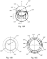
- the modelling aids 1, 100 of the present invention are intended for use with an underlying dental implant component. Such a component is shown in Figs. 15A and 15B .
- Abutment 200 is the separate abutment part of a two-part dental implant. It comprises an apical end 201 and a coronal end 202 with a through bore 203 extending therebetween. Through bore 203 comprises a screw seat 204. Abutment 200 therefore enables a screw to be seated within the component in order to fasten this to an implant.
- connection geometry 210 is provided which is complementary to the dental implant. This enables the abutment 200 to be inserted into a axially extending bore within the dental implant.
- the connection geometry 210 includes an anti-rotation means 212.
- a further anti-rotation means 214 is provided towards the coronal end 202 of the implant. This anti-rotation means 214 comprises four axially extending, evenly circumferentially spaced radial protrusions 215.
- This anti-rotation means 214 is complementary to the anti-rotation section 118 of base part 110 of Fig. 8 .
- the protrusions 215 are therefore sized to fit snugly within grooves 120.
- protrusions 122 on the interior surface of the side wall 112 grip the external surface of the abutment 200 in order to securely connect the base part 110 to the abutment 200.
- the modelling aid 100 is shown in combination with the abutment 200 in FIGs. 16A and 16B .
- the coronal end 114 of the base part 110 rests on the shoulder 216 of the abutment 200 and the protrusions 215 of the anti-rotation means 214 are housed in the grooves 120 of the base part 110.
- the base part 110 is connected to the abutment 200 in a rotationally and axially fixed manner.
- abutment 200 comprises a cut out 213 at its coronal end 202 which is complementary to the cut out 113 of the base part 110. This additionally helps with the passage of the screw and screw driver.
- the modelling aid 100 is positioned on the abutment 200 as shown in FIGs 16A and 16B .
- the angled part 130 can be rotated relative to the base part 110 within the limits set by the rotational stops 142, 152 in order to best position the non-linear channel 138.
- a wax-up is then made of the desired coping, during which the tubular side walls 112, 132 are surrounded by wax.
- the wax-up, together with the modelling aid 100 can then be removed from the abutment and cast, to form a mould. During this process the modelling aid 100 is destroyed.
- the mould is then used to form the coping using, e.g. gold.
- the final coping will contain a screw channel having the shape of the interior wall of the closed channel 160 of the modelling aid 100. This will include the anti-rotation section 118 and thus the final coping can be placed in non-rotational engagement with the abutment 200.
- Figs. 17A-C show abutment 200', which can be used with a modelling aid in accordance with the present invention, the base part 110' of which is shown in Figs. 18A-C .
- Abutment 200' is the separate abutment part of a two-part dental implant. It comprises an apical end 201' and a coronal end 202' with a through bore 203' extending therebetween. Through bore 203' comprises a screw seat 204' . Abutment 200' therefore enables a screw to be seated within the component in order to fasten this to an implant.
- connection geometry 210' On the exterior surface of the abutment 200' a connection geometry 210' is provided which is complementary to the dental implant. This enables the abutment 200' to be inserted into an axially extending bore within the dental implant.
- the connection geometry 210' includes an anti-rotation means 212'.
- a further anti-rotation means 214' is provided towards the coronal end 202' of the abutment.
- This anti-rotation means 214' comprises three axially extending, evenly circumferentially spaced radial protrusions 215', as can best be seen in FIG. 17C .
- base part 110' shown in FIGs 18A-C , is substantively identical to the base part 110 of the second embodiment.
- a tubular side wall 112' extends from an open apical end 114' to an open coronal end 116' along a linear longitudinal axis L B .
- Base part 110' comprises three circumferentially spaced, radially extending protrusions 140' on the exterior surface of the side wall 112'.
- Base part 110' differs from the base part 110 of the second embodiment in that on its interior surface the side wall 112' comprises an anti-rotation section 118' comprising three evenly circumferentially spaced grooves 120', as best seen in FIG. 18B .
- the interior surface of the base part 110' further comprises three inwardly extending protrusions 122', interposed between the grooves 120' of the anti-rotation section 118'.
- the anti-rotation means 214' of abutment 200' is complementary to the anti-rotation section 118' of base part 110'.
- the protrusions 215' are therefore sized to fit snugly within grooves 120'.
- the protrusions 122' on the interior surface of the side wall 112' grip the external surface of the abutment 200' in order to securely connect the base part 110' to the abutment 200'.
- Base part 110' can be used in combination with the angled part 130 shown in Figs. 11 and 12 in respect of the second embodiment.
- protrusion 150 is located between two of the protrusions 140' of the base part 110'.
- the coronal surfaces 144' of the radially extending protrusions 140' form an abutment surface for the apical end 134 of the angled part 130.
- Relative rotation between the base part 110' and angled part 130 is limited by one of the opposing rotational stops 152 of the axially extending protrusion 150 contacting a rotational stop 142' of the base part 110'.
- base part 10 could be adapted for connection to abutment 200' simply by altering the number and shape of grooves 20 and protrusions 22 in line with the grooves 120' and protrusions 122' of base part 110'.
- the radially extending protrusions may be formed on the angled part and the axially extending protrusion on the base part. It is possible for either part to comprise additional radially or axially extending protrusions.
- the angled part can form a friction fit with the interior surface of the base part and/or the anti-rotation section of the base part can be located on the exterior surface.
- the modelling aid of the present invention can be designed for use with a coping or abutment part of a one-piece implant.
- the anti-rotation connection between the implant component, e.g. abutment, and base part can comprise 2-fold or 5-fold and higher rotational symmetry by altering the number of complementary grooves and protrusions.
Landscapes
- Health & Medical Sciences (AREA)
- Oral & Maxillofacial Surgery (AREA)
- Orthopedic Medicine & Surgery (AREA)
- Dentistry (AREA)
- Epidemiology (AREA)
- Life Sciences & Earth Sciences (AREA)
- Animal Behavior & Ethology (AREA)
- General Health & Medical Sciences (AREA)
- Public Health (AREA)
- Veterinary Medicine (AREA)
- Dental Tools And Instruments Or Auxiliary Dental Instruments (AREA)
- Dental Prosthetics (AREA)
- Prostheses (AREA)
Claims (15)
- Aide au modelage en deux parties (1, 100) pour la connexion à un composant d'implant dentaire (200), l'aide au modelage comprenantune partie de base creuse (10, 110) comprenantune extrémité apicale ouverte (14, 114),une extrémité coronale ouverte (16, 116) etune paroi latérale tubulaire (12, 112) s'étendant de l'extrémité apicale à l'extrémité coronale le long d'un axe longitudinal linéaire (LB), la paroi latérale présentantune surface intérieure et une surface extérieure, l'une de ces surfaces comprenant une section anti-rotation (18, 118) ayant une section transversale symétrique non-circulaire dans un plan perpendiculaire à l'axe longitudinal, etune partie angulaire creuse (30, 130) comprenantune extrémité apicale ouverte (34, 134),une extrémité coronale ouverte (36, 136) etune paroi latérale tubulaire (32, 132) s'étendant entre l'extrémité apicale et l'extrémité coronale et présentant une surface intérieure et extérieure, la paroi latérale tubulaire formantune partie apicale (35, 135) de la partie angulaire s'étendant le long d'un premier axe linéaire (L1), etune partie coronale (37, 137) de la partie angulaire s'étendant le long d'un deuxième axe, le deuxième axe n'étant pas coaxial au premier axe de sorte que la paroi latérale tubulaire crée un canal non linéaire (38, 138),la partie apicale est dimensionnée et formée pour former un ajustement par friction avec la partie de base,dans lequel, lorsque la partie de base est connectée à la partie angulaire, un canal fermé (60, 160) est formé, s'étendant de l'extrémité apicale de la partie de base à l'extrémité coronale de la partie angulaire, le premier axe de la partie apicale de la partie angulaire étant coaxial à l'axe longitudinal de la partie de base et la section anti-rotation de la partie de base étant exposée sur une surface de la partie de base,caractérisé en ce que la partie de base (10, 110) et la partie apicale (35, 135) de la partie angulaire (30, 130) comprennent chacune au moins deux arrêts de rotation (42, 142, 52, 152) espacés circonférentiellement, chaque arrêt étant formé par une surface s'étendant radialement et axialement, les arrêts de rotation étant disposés de telle sorte que, lorsque la partie de base est reliée à la partie angulaire, la rotation relative dans l'une ou l'autre direction est limitée par la butée d'un arrêt de rotation de la partie de base contre un arrêt de rotation de la partie angulaire.
- Aide au modelage en deux parties (1, 100) selon la revendication 1, dans laquelle la partie de base (10, 110) et la partie apicale (35, 135) de la partie angulaire (30, 130) comprennent chacune une seule protubérance (40, 140, 50, 150), les côtés opposés de la protubérance formant les arrêts de rotation (42, 142, 52, 152) de chaque partie.
- Aide au modelage en deux parties (1, 100) selon la revendication 1, dans laquelle l'une de la partie de base (10, 110) et la partie apicale (35, 135) de la partie angulaire (30, 130) comprend une seule protubérance (40, 140, 50, 150), dans laquelle les côtés opposés de la protubérance forment les arrêts de rotation (42, 142, 52, 152) de la partie et l'autre partie de la base et la partie apicale de la partie angulaire comprennent au moins deux protubérances (140), dans lesquelles les côtés opposés des protubérances forment les arrêts de rotation (142) de la partie.
- Aide au modelage en deux parties (1, 100) selon la revendication 1, 2 ou 3, dans laquelle les au moins deux arrêts de rotation (42, 142) de l'une des parties de base (10, 110) et de la partie apicale (35, 135) de la partie angulaire (30, 130) sont formés par une ou plusieurs protubérances (40, 140) s'étendant radialement à partir de la paroi latérale tubulaire (12, 112, 32, 132) de la partie et les au moins deux arrêts de rotation (52, 152) de l'autre partie de la base et de la partie apicale de la partie angulaire sont formés par une ou plusieurs protubérances (50, 150) s'étendant axialement à partir de l'extrémité proximale (16, 116, 34, 134) de la partie.
- Aide au modelage en deux parties (1, 100) selon la revendication 4, dans laquelle la ou les protubérances s'étendant radialement (40, 140) comprennent en outre une surface de butée (44, 144) plane et orientée vers le haut, disposée de telle sorte que, lorsque la partie de base est reliée à la partie angulaire, l'extrémité proximale de l'autre partie s'appuie sur celle-ci.
- Aide au modelage en deux parties (1, 100) selon l'une quelconque des revendications précédentes, dans laquelle les arrêts de rotation (42, 142, 52, 152) de la partie de base (10, 110) et la partie apicale (35, 135) de la partie angulaire (30, 130) sont disposés de telle sorte que le degré de liberté de rotation relative entre la partie de base et la partie angulaire est égal à l'angle de symétrie de rotation de la section anti-rotation (18, 118).
- Aide au modelage en deux parties (1, 100) selon l'une quelconque des revendications précédentes, dans laquelle la partie apicale (35, 135) est dimensionnée et formée pour former un ajustement par friction avec la surface extérieure de la partie de base (10, 110).
- Aide au modelage en deux parties selon la revendication 7, dans laquelle les au moins deux arrêts de rotation (52, 152) de la partie apicale (35, 135) de la partie angulaire (30, 130) sont formés par une ou plusieurs protubérances (50, 150) s'étendant axialement à partir de l'extrémité apicale (34, 134) de la partie angulaire et les au moins deux arrêts de rotation (42, 142) de la partie de base (10, 110) sont formés par une ou plusieurs protubérances (40, 140) s'étendant radialement à partir de la surface extérieure de la paroi latérale (12, 112).
- Aide au modelage en deux parties (1, 100) selon l'une quelconque des revendications précédentes, dans laquelle la partie coronale (37, 137) de la partie angulaire (30, 130) s'étend le long d'un deuxième axe linéaire (L2) faisant un angle (α) avec le premier axe (L1), et dans laquelle l'axe central du canal non-linéaire (38, 138) est formé uniquement par le premier axe (L1) et le deuxième axe (L2), qui sont tous deux linéaires mais non-coaxiaux.
- Aide au modelage en deux parties (1, 100) selon l'une quelconque des revendications précédentes, dans laquelle la section anti-rotation (18, 118) est située sur la surface intérieure de la partie de base (10, 110).
- Aide au modelage en deux parties (1, 100) selon l'une quelconque des revendications précédentes, dans laquelle la partie de base (10, 110) comprend une ou plusieurs protubérances (22, 122) s'étendant radialement à partir de la surface de la partie de base sur laquelle la section anti-rotation (18, 118) est située, ladite ou plusieurs protubérances étant disposées pour saisir le composant de l'implant dentaire (200).
- Aide au modelage en deux parties (1, 100) selon l'une quelconque des revendications précédentes, dans laquelle l'une de la partie de base (10, 110) et de la partie angulaire (30, 130) comprend une découpe (13, 113) à son extrémité proximale, dans laquelle, lorsque la partie de base est reliée à la partie angulaire, la découpe est située à l'intérieur du canal fermé (60, 160) formé par les composants.
- Aide au modelage en deux parties selon la revendication 12 lorsqu'elle dépend de la revendication 7 ou 8, dans laquelle la partie de base (10, 110) comprend une découpe (13, 113) à son extrémité coronale (16, 116).
- Aide au modelage en deux parties (1, 100) selon la revendication 13, dans laquelle les arrêts de rotation (42, 142, 52, 152) sont dimensionnés et situés de manière à ce que le canal non linéaire (38, 138) ne puisse pas être tourné hors de l'alignement avec la découpe (13, 113).
- Combinaison d'une aide de modelage (1, 100) selon l'une quelconque des revendications précédentes et d'un composant d'implant dentaire (200), le composant comprenant un trou de vis (203) qui, lorsque aide de modelage est connecté au composant d'implant dentaire, est en communication avec le canal fermé (60, 160) de l'aide de modelage,dans lequel le composant d'implant dentaire (200) comprend en outre une section anti-rotation (214) qui est complémentaire à la section anti-rotation (18, 118) de la partie de base (10, 110), etdans lequel le composant d'implant dentaire (200) est un abutment comprenant une extrémité coronale (202), une extrémité apicale (201) et un alésage traversant (203) s'étendant de l'extrémité apicale à l'extrémité coronale, le abutment comprenant, à son extrémité apicale, un premier moyen anti-rotation (212) pour coopérer avec un implant dentaire et, à son extrémité coronale, un second moyen anti-rotation (214) pour coopérer avec la section anti-rotation (18, 118) de la partie de base (10, 110).
Applications Claiming Priority (2)
| Application Number | Priority Date | Filing Date | Title |
|---|---|---|---|
| EP17161892 | 2017-03-20 | ||
| PCT/EP2018/056846 WO2018172261A1 (fr) | 2017-03-20 | 2018-03-19 | Auxiliaire de modélisation en deux parties |
Publications (2)
| Publication Number | Publication Date |
|---|---|
| EP3886757A1 EP3886757A1 (fr) | 2021-10-06 |
| EP3886757B1 true EP3886757B1 (fr) | 2023-05-31 |
Family
ID=58387758
Family Applications (1)
| Application Number | Title | Priority Date | Filing Date |
|---|---|---|---|
| EP18711942.5A Active EP3886757B1 (fr) | 2017-03-20 | 2018-03-19 | Aide de modélisation en deux parties |
Country Status (6)
| Country | Link |
|---|---|
| US (1) | US11484394B2 (fr) |
| EP (1) | EP3886757B1 (fr) |
| CN (1) | CN110621258B (fr) |
| BR (1) | BR112019018756B1 (fr) |
| ES (1) | ES2946758T3 (fr) |
| WO (1) | WO2018172261A1 (fr) |
Families Citing this family (4)
| Publication number | Priority date | Publication date | Assignee | Title |
|---|---|---|---|---|
| EP3606463B1 (fr) * | 2017-04-07 | 2023-10-25 | Panthera Dental Inc. | Conduit pour vis en forme de goutte pour une superstructure dentaire et son procédé de conception |
| ES2957409T3 (es) | 2021-03-16 | 2024-01-18 | Anthogyr Sa | Base transmucosa con paso pasante longitudinal mejorado |
| US20230414329A1 (en) * | 2022-06-23 | 2023-12-28 | Igor Roshkovan | Dental implant attachment system in screw-retained configuration for implant-supported and implant-retained removable dentures and method of use |
| CZ2022428A3 (cs) | 2022-10-10 | 2024-04-17 | Microdent S.R.O. | Systém vhojovacího tělíska |
Family Cites Families (18)
| Publication number | Priority date | Publication date | Assignee | Title |
|---|---|---|---|---|
| US3322187A (en) | 1965-03-01 | 1967-05-30 | Weissman Bernard | Apparatus for casting by the lost wax process |
| US5527182A (en) * | 1993-12-23 | 1996-06-18 | Adt Advanced Dental Technologies, Ltd. | Implant abutment systems, devices, and techniques |
| JPH1147158A (ja) | 1997-07-30 | 1999-02-23 | G C:Kk | 角度付き歯科用インプラント |
| JPH1147758A (ja) * | 1997-08-06 | 1999-02-23 | Ebara Corp | 微細懸濁物含有水の処理方法 |
| US6951460B2 (en) * | 2001-11-01 | 2005-10-04 | Astra Tech Ab | Components and method for improved impression making |
| US20090035721A1 (en) * | 2006-02-16 | 2009-02-05 | Francisco Javier Garcia Saban | Dental implant and dental impression-taking device assembly |
| EP2076204A4 (fr) | 2006-10-26 | 2009-11-25 | Biomain Ab | Système dentaire |
| ES2335301T3 (es) | 2006-11-10 | 2010-03-24 | Straumann Holding Ag | Soporte de fundicion para un implante dental. |
| US20090298013A1 (en) | 2008-05-27 | 2009-12-03 | Daniel Baruc | Inclined dental abutment assembly device |
| CN201308547Y (zh) * | 2008-12-08 | 2009-09-16 | 威海威高生物技术有限公司 | 圆锥面卡扣式口腔印模转移装置 |
| US20100159417A1 (en) * | 2008-12-18 | 2010-06-24 | Dale Whipple | Dental impression cap with engagement feature |
| CN102018580A (zh) * | 2009-09-11 | 2011-04-20 | 兴达生技有限公司 | 可立即印模的牙科植体安装固定装置 |
| ES2357204B1 (es) | 2009-10-08 | 2012-03-06 | Ramón Farre Berga | Aditamiento para la confección de la estructura interna de prótesis dentales. |
| SE538150C2 (sv) * | 2012-07-11 | 2016-03-22 | Heraeus Kulzer Nordic Ab | En skruvkanalsriktande anordning för en dental superstrukturoch metoder för att tillverka en dental superstruktur |
| WO2014200404A1 (fr) | 2013-06-13 | 2014-12-18 | Brånemark Integration Ab | Prothèse dentaire et procédé de fabrication de la prothèse |
| SE538410C2 (sv) * | 2013-06-13 | 2016-06-14 | Brånemark Integration Ab | Dental protes och en metod för att tillverka protesen |
| CN104546164B (zh) * | 2014-12-11 | 2017-09-29 | 大连三生科技发展有限公司 | 橡胶塞角度印模转移装置 |
| CN109152622A (zh) * | 2016-02-19 | 2019-01-04 | 艾文·埃尔斯纳 | 用于制作牙科假体的印模帽 |
-
2018
- 2018-03-19 US US16/496,293 patent/US11484394B2/en active Active
- 2018-03-19 WO PCT/EP2018/056846 patent/WO2018172261A1/fr unknown
- 2018-03-19 EP EP18711942.5A patent/EP3886757B1/fr active Active
- 2018-03-19 ES ES18711942T patent/ES2946758T3/es active Active
- 2018-03-19 BR BR112019018756-1A patent/BR112019018756B1/pt active IP Right Grant
- 2018-03-19 CN CN201880033210.7A patent/CN110621258B/zh active Active
Also Published As
| Publication number | Publication date |
|---|---|
| ES2946758T3 (es) | 2023-07-25 |
| WO2018172261A1 (fr) | 2018-09-27 |
| EP3886757A1 (fr) | 2021-10-06 |
| US11484394B2 (en) | 2022-11-01 |
| BR112019018756A2 (pt) | 2020-04-07 |
| US20200046468A1 (en) | 2020-02-13 |
| BR112019018756B1 (pt) | 2022-12-06 |
| CN110621258B (zh) | 2022-01-07 |
| CN110621258A (zh) | 2019-12-27 |
Similar Documents
| Publication | Publication Date | Title |
|---|---|---|
| EP3886757B1 (fr) | Aide de modélisation en deux parties | |
| US20120171638A1 (en) | Holding piece for an implant | |
| EP2601906B1 (fr) | Incrustation de butée | |
| JP5976102B2 (ja) | 2部材からなる歯科用部品 | |
| CA2853327C (fr) | Systeme de montage d'un remplacement dentaire | |
| EP3071141B1 (fr) | Implant dentaire | |
| EP2459106B1 (fr) | Elément de montage pour un implant dentaire | |
| US11331171B2 (en) | Implant analog | |
| JP2002200099A (ja) | インプラント上部構造体 | |
| CN110312488B (zh) | 具有引导件和铣刀的系统 | |
| EP4076268B1 (fr) | Butée transépithéliale | |
| EP3831335B1 (fr) | Un ensemble d'implantologie dentaire | |
| JP2018531713A (ja) | 回転防止上部接続部を有する経上皮スリーブを備えた、歯科用インプラントおよび補綴部品のセット |
Legal Events
| Date | Code | Title | Description |
|---|---|---|---|
| STAA | Information on the status of an ep patent application or granted ep patent |
Free format text: STATUS: UNKNOWN |
|
| STAA | Information on the status of an ep patent application or granted ep patent |
Free format text: STATUS: THE INTERNATIONAL PUBLICATION HAS BEEN MADE |
|
| STAA | Information on the status of an ep patent application or granted ep patent |
Free format text: STATUS: THE INTERNATIONAL PUBLICATION HAS BEEN MADE |
|
| PUAI | Public reference made under article 153(3) epc to a published international application that has entered the european phase |
Free format text: ORIGINAL CODE: 0009012 |
|
| STAA | Information on the status of an ep patent application or granted ep patent |
Free format text: STATUS: REQUEST FOR EXAMINATION WAS MADE |
|
| 17P | Request for examination filed |
Effective date: 20191107 |
|
| AK | Designated contracting states |
Kind code of ref document: A1 Designated state(s): AL AT BE BG CH CY CZ DE DK EE ES FI FR GB GR HR HU IE IS IT LI LT LU LV MC MK MT NL NO PL PT RO RS SE SI SK SM TR |
|
| GRAP | Despatch of communication of intention to grant a patent |
Free format text: ORIGINAL CODE: EPIDOSNIGR1 |
|
| STAA | Information on the status of an ep patent application or granted ep patent |
Free format text: STATUS: GRANT OF PATENT IS INTENDED |
|
| INTG | Intention to grant announced |
Effective date: 20221223 |
|
| GRAS | Grant fee paid |
Free format text: ORIGINAL CODE: EPIDOSNIGR3 |
|
| GRAA | (expected) grant |
Free format text: ORIGINAL CODE: 0009210 |
|
| STAA | Information on the status of an ep patent application or granted ep patent |
Free format text: STATUS: THE PATENT HAS BEEN GRANTED |
|
| AK | Designated contracting states |
Kind code of ref document: B1 Designated state(s): AL AT BE BG CH CY CZ DE DK EE ES FI FR GB GR HR HU IE IS IT LI LT LU LV MC MK MT NL NO PL PT RO RS SE SI SK SM TR |
|
| REG | Reference to a national code |
Ref country code: GB Ref legal event code: FG4D Ref country code: CH Ref legal event code: EP |
|
| REG | Reference to a national code |
Ref country code: AT Ref legal event code: REF Ref document number: 1570520 Country of ref document: AT Kind code of ref document: T Effective date: 20230615 Ref country code: DE Ref legal event code: R096 Ref document number: 602018050418 Country of ref document: DE |
|
| REG | Reference to a national code |
Ref country code: IE Ref legal event code: FG4D |
|
| P01 | Opt-out of the competence of the unified patent court (upc) registered |
Effective date: 20230529 |
|
| REG | Reference to a national code |
Ref country code: ES Ref legal event code: FG2A Ref document number: 2946758 Country of ref document: ES Kind code of ref document: T3 Effective date: 20230725 |
|
| REG | Reference to a national code |
Ref country code: NL Ref legal event code: FP |
|
| REG | Reference to a national code |
Ref country code: SE Ref legal event code: TRGR |
|
| REG | Reference to a national code |
Ref country code: LT Ref legal event code: MG9D |
|
| REG | Reference to a national code |
Ref country code: AT Ref legal event code: MK05 Ref document number: 1570520 Country of ref document: AT Kind code of ref document: T Effective date: 20230531 |
|
| PG25 | Lapsed in a contracting state [announced via postgrant information from national office to epo] |
Ref country code: NO Free format text: LAPSE BECAUSE OF FAILURE TO SUBMIT A TRANSLATION OF THE DESCRIPTION OR TO PAY THE FEE WITHIN THE PRESCRIBED TIME-LIMIT Effective date: 20230831 Ref country code: AT Free format text: LAPSE BECAUSE OF FAILURE TO SUBMIT A TRANSLATION OF THE DESCRIPTION OR TO PAY THE FEE WITHIN THE PRESCRIBED TIME-LIMIT Effective date: 20230531 |
|
| PG25 | Lapsed in a contracting state [announced via postgrant information from national office to epo] |
Ref country code: RS Free format text: LAPSE BECAUSE OF FAILURE TO SUBMIT A TRANSLATION OF THE DESCRIPTION OR TO PAY THE FEE WITHIN THE PRESCRIBED TIME-LIMIT Effective date: 20230531 Ref country code: PL Free format text: LAPSE BECAUSE OF FAILURE TO SUBMIT A TRANSLATION OF THE DESCRIPTION OR TO PAY THE FEE WITHIN THE PRESCRIBED TIME-LIMIT Effective date: 20230531 Ref country code: LV Free format text: LAPSE BECAUSE OF FAILURE TO SUBMIT A TRANSLATION OF THE DESCRIPTION OR TO PAY THE FEE WITHIN THE PRESCRIBED TIME-LIMIT Effective date: 20230531 Ref country code: LT Free format text: LAPSE BECAUSE OF FAILURE TO SUBMIT A TRANSLATION OF THE DESCRIPTION OR TO PAY THE FEE WITHIN THE PRESCRIBED TIME-LIMIT Effective date: 20230531 Ref country code: IS Free format text: LAPSE BECAUSE OF FAILURE TO SUBMIT A TRANSLATION OF THE DESCRIPTION OR TO PAY THE FEE WITHIN THE PRESCRIBED TIME-LIMIT Effective date: 20230930 Ref country code: HR Free format text: LAPSE BECAUSE OF FAILURE TO SUBMIT A TRANSLATION OF THE DESCRIPTION OR TO PAY THE FEE WITHIN THE PRESCRIBED TIME-LIMIT Effective date: 20230531 Ref country code: GR Free format text: LAPSE BECAUSE OF FAILURE TO SUBMIT A TRANSLATION OF THE DESCRIPTION OR TO PAY THE FEE WITHIN THE PRESCRIBED TIME-LIMIT Effective date: 20230901 |
|
| PG25 | Lapsed in a contracting state [announced via postgrant information from national office to epo] |
Ref country code: FI Free format text: LAPSE BECAUSE OF FAILURE TO SUBMIT A TRANSLATION OF THE DESCRIPTION OR TO PAY THE FEE WITHIN THE PRESCRIBED TIME-LIMIT Effective date: 20230531 |
|
| PG25 | Lapsed in a contracting state [announced via postgrant information from national office to epo] |
Ref country code: SK Free format text: LAPSE BECAUSE OF FAILURE TO SUBMIT A TRANSLATION OF THE DESCRIPTION OR TO PAY THE FEE WITHIN THE PRESCRIBED TIME-LIMIT Effective date: 20230531 |
|
| PG25 | Lapsed in a contracting state [announced via postgrant information from national office to epo] |
Ref country code: SM Free format text: LAPSE BECAUSE OF FAILURE TO SUBMIT A TRANSLATION OF THE DESCRIPTION OR TO PAY THE FEE WITHIN THE PRESCRIBED TIME-LIMIT Effective date: 20230531 Ref country code: SK Free format text: LAPSE BECAUSE OF FAILURE TO SUBMIT A TRANSLATION OF THE DESCRIPTION OR TO PAY THE FEE WITHIN THE PRESCRIBED TIME-LIMIT Effective date: 20230531 Ref country code: RO Free format text: LAPSE BECAUSE OF FAILURE TO SUBMIT A TRANSLATION OF THE DESCRIPTION OR TO PAY THE FEE WITHIN THE PRESCRIBED TIME-LIMIT Effective date: 20230531 Ref country code: PT Free format text: LAPSE BECAUSE OF FAILURE TO SUBMIT A TRANSLATION OF THE DESCRIPTION OR TO PAY THE FEE WITHIN THE PRESCRIBED TIME-LIMIT Effective date: 20231002 Ref country code: EE Free format text: LAPSE BECAUSE OF FAILURE TO SUBMIT A TRANSLATION OF THE DESCRIPTION OR TO PAY THE FEE WITHIN THE PRESCRIBED TIME-LIMIT Effective date: 20230531 Ref country code: DK Free format text: LAPSE BECAUSE OF FAILURE TO SUBMIT A TRANSLATION OF THE DESCRIPTION OR TO PAY THE FEE WITHIN THE PRESCRIBED TIME-LIMIT Effective date: 20230531 Ref country code: CZ Free format text: LAPSE BECAUSE OF FAILURE TO SUBMIT A TRANSLATION OF THE DESCRIPTION OR TO PAY THE FEE WITHIN THE PRESCRIBED TIME-LIMIT Effective date: 20230531 |
|
| REG | Reference to a national code |
Ref country code: DE Ref legal event code: R097 Ref document number: 602018050418 Country of ref document: DE |
|
| PLBE | No opposition filed within time limit |
Free format text: ORIGINAL CODE: 0009261 |
|
| STAA | Information on the status of an ep patent application or granted ep patent |
Free format text: STATUS: NO OPPOSITION FILED WITHIN TIME LIMIT |
|
| PGFP | Annual fee paid to national office [announced via postgrant information from national office to epo] |
Ref country code: NL Payment date: 20240320 Year of fee payment: 7 |
|
| PGFP | Annual fee paid to national office [announced via postgrant information from national office to epo] |
Ref country code: DE Payment date: 20240320 Year of fee payment: 7 Ref country code: GB Payment date: 20240321 Year of fee payment: 7 |
|
| PG25 | Lapsed in a contracting state [announced via postgrant information from national office to epo] |
Ref country code: SI Free format text: LAPSE BECAUSE OF FAILURE TO SUBMIT A TRANSLATION OF THE DESCRIPTION OR TO PAY THE FEE WITHIN THE PRESCRIBED TIME-LIMIT Effective date: 20230531 |
|
| 26N | No opposition filed |
Effective date: 20240301 |