EP4076268B1 - Butée transépithéliale - Google Patents
Butée transépithéliale Download PDFInfo
- Publication number
- EP4076268B1 EP4076268B1 EP21716650.3A EP21716650A EP4076268B1 EP 4076268 B1 EP4076268 B1 EP 4076268B1 EP 21716650 A EP21716650 A EP 21716650A EP 4076268 B1 EP4076268 B1 EP 4076268B1
- Authority
- EP
- European Patent Office
- Prior art keywords
- abutment
- lower body
- screw
- dental
- implant
- Prior art date
- Legal status (The legal status is an assumption and is not a legal conclusion. Google has not performed a legal analysis and makes no representation as to the accuracy of the status listed.)
- Active
Links
- 239000007943 implant Substances 0.000 claims description 36
- 239000011796 hollow space material Substances 0.000 claims description 17
- 239000004053 dental implant Substances 0.000 claims description 14
- 238000003466 welding Methods 0.000 claims description 4
- 238000000034 method Methods 0.000 description 12
- 239000000560 biocompatible material Substances 0.000 description 5
- 238000013461 design Methods 0.000 description 4
- 230000008878 coupling Effects 0.000 description 3
- 238000010168 coupling process Methods 0.000 description 3
- 238000005859 coupling reaction Methods 0.000 description 3
- 238000003780 insertion Methods 0.000 description 3
- 230000037431 insertion Effects 0.000 description 3
- 210000000988 bone and bone Anatomy 0.000 description 2
- 239000004568 cement Substances 0.000 description 2
- 230000001055 chewing effect Effects 0.000 description 2
- 230000000295 complement effect Effects 0.000 description 2
- 238000012937 correction Methods 0.000 description 2
- 238000003754 machining Methods 0.000 description 2
- 229910052751 metal Inorganic materials 0.000 description 2
- 239000002184 metal Substances 0.000 description 2
- 238000010883 osseointegration Methods 0.000 description 2
- 238000005245 sintering Methods 0.000 description 2
- 238000001356 surgical procedure Methods 0.000 description 2
- 229910001020 Au alloy Inorganic materials 0.000 description 1
- 239000004696 Poly ether ether ketone Substances 0.000 description 1
- 229910001069 Ti alloy Inorganic materials 0.000 description 1
- RTAQQCXQSZGOHL-UHFFFAOYSA-N Titanium Chemical compound [Ti] RTAQQCXQSZGOHL-UHFFFAOYSA-N 0.000 description 1
- QCWXUUIWCKQGHC-UHFFFAOYSA-N Zirconium Chemical compound [Zr] QCWXUUIWCKQGHC-UHFFFAOYSA-N 0.000 description 1
- 230000006978 adaptation Effects 0.000 description 1
- 210000003484 anatomy Anatomy 0.000 description 1
- 239000005557 antagonist Substances 0.000 description 1
- JUPQTSLXMOCDHR-UHFFFAOYSA-N benzene-1,4-diol;bis(4-fluorophenyl)methanone Chemical compound OC1=CC=C(O)C=C1.C1=CC(F)=CC=C1C(=O)C1=CC=C(F)C=C1 JUPQTSLXMOCDHR-UHFFFAOYSA-N 0.000 description 1
- 238000007796 conventional method Methods 0.000 description 1
- 239000003353 gold alloy Substances 0.000 description 1
- 230000035876 healing Effects 0.000 description 1
- 238000002513 implantation Methods 0.000 description 1
- 239000000463 material Substances 0.000 description 1
- 238000002844 melting Methods 0.000 description 1
- 230000008018 melting Effects 0.000 description 1
- 238000003801 milling Methods 0.000 description 1
- 239000010955 niobium Substances 0.000 description 1
- 229920002530 polyetherether ketone Polymers 0.000 description 1
- 229910052719 titanium Inorganic materials 0.000 description 1
- 239000010936 titanium Substances 0.000 description 1
- 210000004746 tooth root Anatomy 0.000 description 1
- 238000011282 treatment Methods 0.000 description 1
- 229910052726 zirconium Inorganic materials 0.000 description 1
Images


Classifications
-
- A—HUMAN NECESSITIES
- A61—MEDICAL OR VETERINARY SCIENCE; HYGIENE
- A61C—DENTISTRY; APPARATUS OR METHODS FOR ORAL OR DENTAL HYGIENE
- A61C8/00—Means to be fixed to the jaw-bone for consolidating natural teeth or for fixing dental prostheses thereon; Dental implants; Implanting tools
- A61C8/0048—Connecting the upper structure to the implant, e.g. bridging bars
- A61C8/005—Connecting devices for joining an upper structure with an implant member, e.g. spacers
- A61C8/0068—Connecting devices for joining an upper structure with an implant member, e.g. spacers with an additional screw
-
- A—HUMAN NECESSITIES
- A61—MEDICAL OR VETERINARY SCIENCE; HYGIENE
- A61C—DENTISTRY; APPARATUS OR METHODS FOR ORAL OR DENTAL HYGIENE
- A61C8/00—Means to be fixed to the jaw-bone for consolidating natural teeth or for fixing dental prostheses thereon; Dental implants; Implanting tools
- A61C8/0048—Connecting the upper structure to the implant, e.g. bridging bars
- A61C8/005—Connecting devices for joining an upper structure with an implant member, e.g. spacers
- A61C8/0053—Connecting devices for joining an upper structure with an implant member, e.g. spacers with angular adjustment means, e.g. ball and socket joint
-
- A—HUMAN NECESSITIES
- A61—MEDICAL OR VETERINARY SCIENCE; HYGIENE
- A61C—DENTISTRY; APPARATUS OR METHODS FOR ORAL OR DENTAL HYGIENE
- A61C8/00—Means to be fixed to the jaw-bone for consolidating natural teeth or for fixing dental prostheses thereon; Dental implants; Implanting tools
- A61C8/0048—Connecting the upper structure to the implant, e.g. bridging bars
- A61C8/005—Connecting devices for joining an upper structure with an implant member, e.g. spacers
- A61C8/0066—Connecting devices for joining an upper structure with an implant member, e.g. spacers with positioning means
-
- A—HUMAN NECESSITIES
- A61—MEDICAL OR VETERINARY SCIENCE; HYGIENE
- A61C—DENTISTRY; APPARATUS OR METHODS FOR ORAL OR DENTAL HYGIENE
- A61C8/00—Means to be fixed to the jaw-bone for consolidating natural teeth or for fixing dental prostheses thereon; Dental implants; Implanting tools
- A61C8/0089—Implanting tools or instruments
Definitions
- the present invention a transepithelial abutment, relates to a device used as an attachment between an implant and a dental prosthesis, the main purpose of which is to provide solutions to problems associated with prosthesis height and angulation.
- the transepithelial abutment or device is preferably made of a biocompatible material and is anchored to and integral with the dental implant.
- the field of application is the field of dentistry and it relates particularly to the interface devices for fixing prostheses in dental implants, mounted on the upper and lower jaws, and on which the prosthesis, which can be a crown or a dental structure, such as a bridge, or a complete dental prosthesis, is coupled.
- the prosthesis which can be a crown or a dental structure, such as a bridge, or a complete dental prosthesis, is coupled.
- dental implantology techniques allow replacing dental roots by means of dental implants made of a biocompatible material, usually some sort of titanium alloy, to which the corresponding artificial teeth or prostheses are in turn coupled.
- the implantation phases of said implants are summarized in an initial implant insertion phase, followed by a subsequent intermediate osseointegration phase which involves a wait time, up to the last definitive prosthesis fixing phase.
- a provisional prosthesis that is as similar as possible to the definitive prosthesis can be placed on the implant, which will allow making early use thereof with or without functional loads, but achieving the esthetic function immediately.
- the final position of the implant will always depend on the bone structure resulting from the osseointegration process and on the insertion positions, from the position antagonist to the implant being placed to the inclined positions of the implant, that usually range between 0° and 45°, with the latter being the most unfavorable.
- Transepithelial abutments are one of the products most highly regarded by users among prosthetic solutions. These abutments which act as an attachment between the implant and the dental prosthesis (complete prostheses, crown, or bridge), have different features and advantages which allow improving the precision and comfort in dental procedures, as well as preventing possible complications for the patient. Examples of abutments are disclosed in US6663388B1 and EP2266498B1 .
- the all-on-four technique which is an implantology technique for solving full-arch treatments with only 4 implants and with the placement of a fixed prosthesis along the entire arch on the same day of the surgery stands out among the known techniques.
- the main objective of the present invention is to develop a transepithelial abutment which allows correcting the closure position of the dental implant with the dental prosthesis in height and/or inclination between 0°, greater than 0°, preferably 5°, and 45° with respect to the position of the axis of the implant.
- the present invention therefore relates to an angled transepithelial abutment that is made of a biocompatible material and has a direct connection to a endosseous dental implant, particularly designed for being used both in multiple prosthetic restoration and in single crowns.
- a first object of the present invention is a transepithelial abutment according to claim 1.
- Said abutment comprises three components:
- the transepithelial abutment object of the invention is made up of three components assembled such that they form a single device.
- the transepithelial abutment is made up of two bodies that are integrally attached and a screw that remains captive inside the two preceding bodies as a third integrating component of the transepithelial abutment.
- the dental structure or prosthesis which is preferably attached to the abutment by means of a second screw, and the lower body is fitted and fixed directly on the implant with the help of the captive screw which is part of the abutment object of the invention.
- the three components form one and the same part, i.e., a single device.
- the upper body is attached or coupled on the lower body such that this is permanent, i.e., both bodies are integral with one another, preventing them from being able to come apart.
- the transepithelial abutment object of the present invention is designed for being used in the upper or lower jaw and supporting tooth replacement for the purpose of restoring chewing function and esthetics. These abutments, in combination with endosseous implants, are indicated for both multiple and single tooth restorations. Other additional features of the present transepithelial abutment are:
- Figure 1 shows an angled transepithelial abutment according to the present invention formed by three parts or components, i.e., an upper body 20, a lower body 30, and a captive screw 40 between both parts.
- the upper body 20 and the lower body 30 are attached by means of welding between the two upper and lower bodies,
- the screw 40 After the attachment or coupling of the upper body 20 and the lower body 30, the screw 40 remains captive inside the assembly formed by the two bodies and the three components forming a single device or abutment. Both the upper body 20 and the lower body 30 are hollow and they therefore allow the screw 40 to remain captive inside both bodies, between them, mainly in the hollow inner housing of the lower body 30, the upper body 20 preventing the screw 40 from coming out. This configuration gives rise to the transepithelial abutment object of the present invention.
- Figure 2 shows on the left side an angled abutment with the upper body 20, 25 separated from the lower body 30 prior to the coupling or attachment between both.
- the abutment on the left side has an upper body 20 with an anti-rotational configuration and the abutment on the right side has an upper body 25 with a rotational configuration.
- This configuration mainly affects the arrangement of the prosthesis, single crown, or dental element on the upper body 20, 25, such that a rotational upper body 25 will be arranged if the prosthesis or dental element is to be moved with respect to the upper body and a non-rotational upper body 20 will be arranged if it must not move.
- Figure 3 shows the two abutments of Figure 2 but assembled, coupled, or attached to one another integrally, forming the single device or abutment object of the present invention.
- Figure 4 shows a front view of two angled abutments, the one on the left side having a non-rotational upper body 20 and the one on the right side having a rotational upper body 25.
- the way in which the upper body, in any of its two preferred forms, has an upper opening or chimney and a thread 21 therein for placing and attaching other possible dental components with a screw through said upper body 20, 25 can be seen.
- the way in which the lower body 30 has a lower geometry 31 which will depend on the type of dental implant to which the abutment will be connected can also be seen in this figure.
- the thread 41 of the screw 40 which is placed captive inside the lower body 30 and whose movement is limited by the upper body 20, 25, projects from the lower portion.
- planar upper base 70 also acts as a support base on which the dental structure or possible dental components which are coupled to the abutment rest. Said planar base 70 maintains its geometry and the same amplitude, or width, along its entire perimeter so that said prosthesis or dental components will have a constant, balanced support resulting in said components sitting better on the abutment.
- the lower portion of the lower body 30 located below the planar upper base 70 will also depend on the implant to which the abutment will be coupled, given that said lower portion of the abutment will be fixed to the jaw or mandibular implant as it is introduced therein. Therefore, the design of this lower body 30 will vary according to the type of implant to be used, and likewise the screw 40 will also depend on the type of implant. The way in which the screw 40 remains captive inside the lower body 30, respecting the upper opening or chimney 26 of the abutment arranged in the upper body 20, 25, can also be seen.
- Figure 5 shows a side exploded view of the components of an angled abutment, in this example a non-rotational angled abutment, object of the present invention. Specifically, an angled lower body 30, a screw 40 introduced in the lower body 30, and an upper body 20 arranged on said lower body 30, thereby forming a single device or abutment, are seen.
- the transepithelial abutment allows angulations of between more than 0°, preferably 5°, and 45° with respect to the axis of the implant, depending mainly on the configuration of the lower body 30 for which said lower body can have different configurations depending on the required angle of inclination.
- the lower body has a hollow space which is not straight and is determined by at least two axes, the first vertical axis "a”, coinciding with the axis of the dental implant when the abutment is connected with said implant, and a second axis "b", which is angled with respect to the first axis and perpendicular to the upper base 70 of the lower body 30.
- the angle formed by the first axis "a” with the second axis "b” determines the inclination of the abutment, and specifically the inclination of the upper body 20 of the abutment.
- the lower body 30 will have one configuration or another, i.e., there will be as many lower bodies as the number of inclinations that are required, for which the inclination of axis "b" with respect to axis "a” will vary.
- the angle between both axes can vary between more than 0°, preferably 5°, and 45°.
- Figure 6 shows a section of the angled abutment of Figure 5 , specifically an abutment with its three components:
- the lower base 24 of the upper body 20 is introduced in the housing 38 of the lower body 30 such that by means of different attachment means 50 both bodies will be integrally attached and the screw 40 will remain captive between both, with the seating of the head 41 of the screw 40 being supported on the seating 37 in the hollow space 36 of the lower body 30.
- Figure 7 shows a side view of an angled abutment object of the invention and a section of said side view. The three components of the abutment can be seen therein.
- the upper bodies 20 do not depend on the lower body 30 and that, regardless of the angulation of said lower bodies 30, the upper body 20 may incorporate a rotational or non-rotational configuration 25.
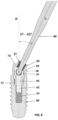
- Figure 8 shows a section of an angled abutment object of the invention connected on a dental implant 90 with the help of a screwdriver 80 in charge of screwing the screw 40 onto the inner thread 91 of the implant 90.
- the lower portion of the lower body 30 is placed inside the implant 90, making the outer end 31 of the lower body 30 coincides, the geometry of which depends on the implant, and the thread 42 of the screw 40 is subsequently screwed into the thread 91 inside the implant 90.
- Access to the head 41 of the screw 40 is achieved through the hollow space 26 of the upper body 20 which the screwdriver 80 goes through.
- a dental prosthesis which will be supported on the upper or support base 70 of the lower body 30, surrounding said upper body, or another dental device, such as an interface acting as an attachment between the abutment and the prosthesis, can be arranged, but also being supported on the support base 70.
- Said support 70 on which the dental structure or other possible dental components are supported maintains its geometry, maintaining the same surface along its entire perimeter, so that it will therefore have greater support in future structures and complementary components that are installed on the abutment, improving biological closure and the distribution of different chewing loads of the dental structure arranged on the abutment and towards the implant.
- the angle of inclination of the angled abutment can vary between more than 0° and 45°, preferably between 5° and 45°, depending on requirements, such that there will be one transepithelial abutment for each required inclination, i.e., one angled abutment with 25° where the angle between axis "a” and axis “b” is 25°, one angled abutment with 15° where the angle between axis "a” and axis “b” is 15°, or one angled abutment with 40° where the angle between axis "a” and axis "b” is 40°.
- Figure 9 shows an abutment object of the invention on which there is arranged an intermediate dental element 95, or an interface, which is secured to the upper body 20 of the abutment object of the invention through a screw 96 which is screwed into the inner thread 21 of the hollow space 26 of the upper body 20.
- the prosthesis or tooth P is arranged on said intermediate dental element 95.
- Said intermediate dental element 95 is completely supported on the support base 70 with a surface with constant dimensions around the upper body 20.
- the retaining screw 96 of the intermediate element 95 is screwed with a screwdriver 80 which can be inclined between more than 0° and 30° between axis "b" and axis "c" of the screwdriver.
- the maximum value of correction would be the sum of the two subsequent angles, the angle between axis "a” and axis "b”, corrected by the abutment object of the invention, up to 45°, and the angle between axis "b” and axis "c”, corrected by the intermediate element 95, or interface, up to 30° (which will depend on the type of interface), the resulting angle of correction in this case therefore being between more than 0°, preferably 5°, and 75°..
- Figure 10 shows another example in which the tooth or dental prosthesis P, manufactured by means of CAD-CAM, is directly fitted in and supported on the support base 70 of the upper base of the upper body 20, 25 of the abutment with an angled lower body 30, object of the invention, fixing the prosthetic assembly P on the abutment object of the invention with a screw 96, specifically screwing said screw 96 onto the upper body 20 of the abutment object of the invention.
- the retaining screw 96 is screwed with a screwdriver 80 which in this case, due to the configuration of the prosthesis P, can correct an inclination that is the same as in the preceding example, i.e., up to 45° on the part of the transepithelial abutment object of the invention plus up to 30° on the part of the CAD-CAM structure, i.e., between more than 0°, preferably 5°, and 75°, with respect to the axis of the implant which coincides with vertical axis "a" of the abutment.
Landscapes
- Health & Medical Sciences (AREA)
- Oral & Maxillofacial Surgery (AREA)
- Orthopedic Medicine & Surgery (AREA)
- Dentistry (AREA)
- Epidemiology (AREA)
- Life Sciences & Earth Sciences (AREA)
- Animal Behavior & Ethology (AREA)
- General Health & Medical Sciences (AREA)
- Public Health (AREA)
- Veterinary Medicine (AREA)
- Dental Prosthetics (AREA)
Claims (6)
- Pilier transépithélial pour l'attache d'une prothèse (P) avec un implant dentaire (90), ledit pilier étant constitué de trois composants :- un corps supérieur (20, 25) où une prothèse dentaire (P) ou un dispositif dentaire (95) doit être disposé, pourvu d'une base supérieure (23) et d'une base inférieure (24) toutes deux reliées par un espace creux traversant (26) ayant un filetage interne (21),- un corps inférieur (30) pour relier avec l'implant dentaire (90), pourvu d'une base supérieure (70) et d'une base inférieure (33) reliées par un logement interne (38), ladite base supérieure (70) du corps inférieur (30) ayant une surface plane autour de l'ouverture du logement interne (38) et le logement interne (38) ayant un appui (37) pour recevoir la tête (41) d'une vis (40), dans lequel un premier segment inférieur du logement interne du corps inférieur s'étend le long d'un premier axe « a » et un second segment supérieur dudit logement interne s'étend le long d'un second axe « b » formant un angle par rapport audit premier axe « a » et étant perpendiculaire à la base supérieure (70) dudit corps inférieur (30), et- une vis (40) à l'intérieur du logement interne (38) du corps inférieur (30), la tête (41) de la vis étant située au-dessus de l'appui (37),le corps supérieur (20, 25) étant d'un seul tenant avec le corps inférieur (30), la base inférieure (24) du corps supérieur (20, 25) étant introduite et attachée dans l'ouverture du logement (38) du corps inférieur (30) avec un moyen d'attache permanent, formant de cette manière un dispositif unique où la vis (40) reste prisonnière entre les deux corps (20, 25, 30), des déplacements de la vis (40) au sein du logement interne (38) du corps inférieur (30) étant limités par le corps supérieur (20, 25).
- Pilier selon la revendication 1, caractérisé en ce que la surface plane de la base supérieure (70) du corps inférieur (30) a une largeur constante.
- Pilier selon la revendication 1, caractérisé en ce que ledit moyen d'attache est une soudure entre les deux corps (20, 25, 30).
- Pilier selon l'une quelconque des revendications précédentes, caractérisé en ce que le corps supérieur (20, 25) a une configuration externe rotationnelle (25) ou anti-rotationnelle (20).
- Pilier selon l'une quelconque des revendications précédentes, caractérisé en ce que la géométrie inférieure du corps inférieur (30) a une configuration externe adaptée à l'implant (90) dans lequel il sera installé.
- Pilier selon la revendication 1, caractérisé en ce que l'angle entre les premier (a) et second (b) axes est supérieur à 0°, de préférence compris entre 5° et 45°.
Applications Claiming Priority (3)
| Application Number | Priority Date | Filing Date | Title |
|---|---|---|---|
| ES202030580U ES1247211Y (es) | 2020-03-31 | 2020-03-31 | Pilar transepitelial |
| EP20382249.9A EP3888587A1 (fr) | 2020-03-31 | 2020-03-31 | Pilier transépithélial |
| PCT/EP2021/058108 WO2021198153A1 (fr) | 2020-03-31 | 2021-03-29 | Butée transépithéliale |
Publications (3)
| Publication Number | Publication Date |
|---|---|
| EP4076268A1 EP4076268A1 (fr) | 2022-10-26 |
| EP4076268B1 true EP4076268B1 (fr) | 2023-09-27 |
| EP4076268C0 EP4076268C0 (fr) | 2023-09-27 |
Family
ID=75396734
Family Applications (1)
| Application Number | Title | Priority Date | Filing Date |
|---|---|---|---|
| EP21716650.3A Active EP4076268B1 (fr) | 2020-03-31 | 2021-03-29 | Butée transépithéliale |
Country Status (5)
| Country | Link |
|---|---|
| US (1) | US20230329844A1 (fr) |
| EP (1) | EP4076268B1 (fr) |
| ES (1) | ES2963215T3 (fr) |
| PL (1) | PL4076268T3 (fr) |
| WO (1) | WO2021198153A1 (fr) |
Family Cites Families (2)
| Publication number | Priority date | Publication date | Assignee | Title |
|---|---|---|---|---|
| US6663388B1 (en) * | 1998-12-28 | 2003-12-16 | Institut Straumann Ag | Connection between a dental implant and an abutment |
| US8142193B2 (en) * | 2009-06-25 | 2012-03-27 | Bar Shalom Eliezer | Compound angular joint for connecting an abutment to a dental implant in a predefined angle |
-
2021
- 2021-03-29 EP EP21716650.3A patent/EP4076268B1/fr active Active
- 2021-03-29 PL PL21716650.3T patent/PL4076268T3/pl unknown
- 2021-03-29 ES ES21716650T patent/ES2963215T3/es active Active
- 2021-03-29 WO PCT/EP2021/058108 patent/WO2021198153A1/fr active Search and Examination
- 2021-03-29 US US17/798,448 patent/US20230329844A1/en active Pending
Also Published As
| Publication number | Publication date |
|---|---|
| ES2963215T3 (es) | 2024-03-25 |
| WO2021198153A1 (fr) | 2021-10-07 |
| EP4076268A1 (fr) | 2022-10-26 |
| EP4076268C0 (fr) | 2023-09-27 |
| US20230329844A1 (en) | 2023-10-19 |
| PL4076268T3 (pl) | 2024-02-26 |
Similar Documents
| Publication | Publication Date | Title |
|---|---|---|
| EP1993469B1 (fr) | Butée dentaire céramique/métallique et implant dentaire | |
| EP2025302B1 (fr) | Un assemblage dentaire pour un procédé de formation de prothèses dentaires | |
| CA2044927C (fr) | Systeme de collet et de pivot pour implants | |
| US20040259056A1 (en) | Prosthetic implant | |
| US20050136378A1 (en) | Implant system and method of installation thereof | |
| US10383710B2 (en) | Configurations for the connection of dental restorations with abutments | |
| WO2006084346A1 (fr) | Systeme et kit d'implant et procede pour son installation | |
| KR100662583B1 (ko) | 크라운 임시고정용 임플란트 유니트 | |
| CA2853327C (fr) | Systeme de montage d'un remplacement dentaire | |
| WO2019017813A1 (fr) | Implant dentaire, vis de connexion et ensemble pour implantation | |
| EP4076268B1 (fr) | Butée transépithéliale | |
| EP3888587A1 (fr) | Pilier transépithélial | |
| Dario | Implant angulation and position and screw or cement retention: clinical guidelines | |
| US11896458B1 (en) | Dental implant abumtment system and method of use | |
| US20130236855A1 (en) | Premanufactured ceramic dental implant abutments for mating ceramic prosthetic build-up construction | |
| ES1247211U (es) | Pilar transepitelial | |
| KR102500193B1 (ko) | 보철물이 적절하게 나사조임되거나 클립 유지되는 것을 허용하는 치과 임플란트 상의 보철물을 위한 듀얼 고정 시스템 | |
| CN117959019A (zh) | 一种内部跨上皮基台 | |
| EP4147667A1 (fr) | Implantodontie avec composants sphériques | |
| EP3551123B1 (fr) | Système adaptateur pour prothèse dentaire |
Legal Events
| Date | Code | Title | Description |
|---|---|---|---|
| STAA | Information on the status of an ep patent application or granted ep patent |
Free format text: STATUS: UNKNOWN |
|
| STAA | Information on the status of an ep patent application or granted ep patent |
Free format text: STATUS: THE INTERNATIONAL PUBLICATION HAS BEEN MADE |
|
| PUAI | Public reference made under article 153(3) epc to a published international application that has entered the european phase |
Free format text: ORIGINAL CODE: 0009012 |
|
| STAA | Information on the status of an ep patent application or granted ep patent |
Free format text: STATUS: REQUEST FOR EXAMINATION WAS MADE |
|
| 17P | Request for examination filed |
Effective date: 20220721 |
|
| AK | Designated contracting states |
Kind code of ref document: A1 Designated state(s): AL AT BE BG CH CY CZ DE DK EE ES FI FR GB GR HR HU IE IS IT LI LT LU LV MC MK MT NL NO PL PT RO RS SE SI SK SM TR |
|
| DAV | Request for validation of the european patent (deleted) | ||
| DAX | Request for extension of the european patent (deleted) | ||
| GRAP | Despatch of communication of intention to grant a patent |
Free format text: ORIGINAL CODE: EPIDOSNIGR1 |
|
| STAA | Information on the status of an ep patent application or granted ep patent |
Free format text: STATUS: GRANT OF PATENT IS INTENDED |
|
| INTG | Intention to grant announced |
Effective date: 20230706 |
|
| GRAS | Grant fee paid |
Free format text: ORIGINAL CODE: EPIDOSNIGR3 |
|
| GRAA | (expected) grant |
Free format text: ORIGINAL CODE: 0009210 |
|
| STAA | Information on the status of an ep patent application or granted ep patent |
Free format text: STATUS: THE PATENT HAS BEEN GRANTED |
|
| AK | Designated contracting states |
Kind code of ref document: B1 Designated state(s): AL AT BE BG CH CY CZ DE DK EE ES FI FR GB GR HR HU IE IS IT LI LT LU LV MC MK MT NL NO PL PT RO RS SE SI SK SM TR |
|
| REG | Reference to a national code |
Ref country code: GB Ref legal event code: FG4D |
|
| REG | Reference to a national code |
Ref country code: CH Ref legal event code: EP |
|
| REG | Reference to a national code |
Ref country code: DE Ref legal event code: R096 Ref document number: 602021005477 Country of ref document: DE |
|
| REG | Reference to a national code |
Ref country code: IE Ref legal event code: FG4D |
|
| REG | Reference to a national code |
Ref country code: RO Ref legal event code: EPE |
|
| U01 | Request for unitary effect filed |
Effective date: 20231017 |
|
| U07 | Unitary effect registered |
Designated state(s): AT BE BG DE DK EE FI FR IT LT LU LV MT NL PT SE SI Effective date: 20231026 |
|
| PG25 | Lapsed in a contracting state [announced via postgrant information from national office to epo] |
Ref country code: GR Free format text: LAPSE BECAUSE OF FAILURE TO SUBMIT A TRANSLATION OF THE DESCRIPTION OR TO PAY THE FEE WITHIN THE PRESCRIBED TIME-LIMIT Effective date: 20231228 |
|
| PG25 | Lapsed in a contracting state [announced via postgrant information from national office to epo] |
Ref country code: RS Free format text: LAPSE BECAUSE OF FAILURE TO SUBMIT A TRANSLATION OF THE DESCRIPTION OR TO PAY THE FEE WITHIN THE PRESCRIBED TIME-LIMIT Effective date: 20230927 Ref country code: NO Free format text: LAPSE BECAUSE OF FAILURE TO SUBMIT A TRANSLATION OF THE DESCRIPTION OR TO PAY THE FEE WITHIN THE PRESCRIBED TIME-LIMIT Effective date: 20231227 Ref country code: HR Free format text: LAPSE BECAUSE OF FAILURE TO SUBMIT A TRANSLATION OF THE DESCRIPTION OR TO PAY THE FEE WITHIN THE PRESCRIBED TIME-LIMIT Effective date: 20230927 Ref country code: GR Free format text: LAPSE BECAUSE OF FAILURE TO SUBMIT A TRANSLATION OF THE DESCRIPTION OR TO PAY THE FEE WITHIN THE PRESCRIBED TIME-LIMIT Effective date: 20231228 |
|
| REG | Reference to a national code |
Ref country code: ES Ref legal event code: FG2A Ref document number: 2963215 Country of ref document: ES Kind code of ref document: T3 Effective date: 20240325 |
|
| PG25 | Lapsed in a contracting state [announced via postgrant information from national office to epo] |
Ref country code: IS Free format text: LAPSE BECAUSE OF FAILURE TO SUBMIT A TRANSLATION OF THE DESCRIPTION OR TO PAY THE FEE WITHIN THE PRESCRIBED TIME-LIMIT Effective date: 20240127 |
|
| U20 | Renewal fee paid [unitary effect] |
Year of fee payment: 4 Effective date: 20240308 |
|
| PG25 | Lapsed in a contracting state [announced via postgrant information from national office to epo] |
Ref country code: SM Free format text: LAPSE BECAUSE OF FAILURE TO SUBMIT A TRANSLATION OF THE DESCRIPTION OR TO PAY THE FEE WITHIN THE PRESCRIBED TIME-LIMIT Effective date: 20230927 Ref country code: IS Free format text: LAPSE BECAUSE OF FAILURE TO SUBMIT A TRANSLATION OF THE DESCRIPTION OR TO PAY THE FEE WITHIN THE PRESCRIBED TIME-LIMIT Effective date: 20240127 Ref country code: CZ Free format text: LAPSE BECAUSE OF FAILURE TO SUBMIT A TRANSLATION OF THE DESCRIPTION OR TO PAY THE FEE WITHIN THE PRESCRIBED TIME-LIMIT Effective date: 20230927 Ref country code: SK Free format text: LAPSE BECAUSE OF FAILURE TO SUBMIT A TRANSLATION OF THE DESCRIPTION OR TO PAY THE FEE WITHIN THE PRESCRIBED TIME-LIMIT Effective date: 20230927 |
|
| PGFP | Annual fee paid to national office [announced via postgrant information from national office to epo] |
Ref country code: RO Payment date: 20240306 Year of fee payment: 4 |