EP3885183B1 - Schiene-zu-boden-spannungsunterdrückungssystem - Google Patents
Schiene-zu-boden-spannungsunterdrückungssystem Download PDFInfo
- Publication number
- EP3885183B1 EP3885183B1 EP21162501.7A EP21162501A EP3885183B1 EP 3885183 B1 EP3885183 B1 EP 3885183B1 EP 21162501 A EP21162501 A EP 21162501A EP 3885183 B1 EP3885183 B1 EP 3885183B1
- Authority
- EP
- European Patent Office
- Prior art keywords
- rail
- ground voltage
- voltage
- ground
- control device
- Prior art date
- Legal status (The legal status is an assumption and is not a legal conclusion. Google has not performed a legal analysis and makes no representation as to the accuracy of the status listed.)
- Active
Links
Images





Classifications
-
- B—PERFORMING OPERATIONS; TRANSPORTING
- B60—VEHICLES IN GENERAL
- B60M—POWER SUPPLY LINES, AND DEVICES ALONG RAILS, FOR ELECTRICALLY- PROPELLED VEHICLES
- B60M5/00—Arrangements along running rails or at joints thereof for current conduction or insulation, e.g. safety devices for reducing earth currents
- B60M5/02—Means for reducing potential difference between rail and adjacent ground
Definitions
- the present invention relates to a rail-to-ground voltage suppression system.
- an electrical substation as a power source and a vehicle as a load are each connected to an overhead line as a positive electrode and a rail as a negative electrode to form an electric circuit, thereby supplying an electric power necessary for running of the vehicle. That is, during the vehicle running, a current flows from the electrical substation to the vehicle through the overhead line as the positive electrode, and a current flows (return current) from the vehicle to the electrical substation through the rail as the negative electrode.
- the return current causes a voltage drop in the rail between the electrical substation and the vehicle, thus causing an electric potential difference (rail-to-ground voltage) between the rail and the ground as an electric potential reference in accordance with a distribution of the voltage drop on the entire train line. Since an excessive rail-to-ground voltage causes a risk of electrical shock when a railway worker touches the rail, recently, as indicated by the international standard IEC62128, it is required to keep the rail-to-ground voltage within a predetermined range (see IEC62128-1:2013. Railway applications-Fixed installations-Electrical safety, earthing and the return circuit-Part 1: Protective provisions against electric shock, IEC62128-2:2013.
- a device for suppressing the rail-to-ground voltage is introduced.
- VLD Voltage Limiting Device
- a short circuit switch is disposed between a rail and an earth, and a short circuit is caused between the rail and the earth when the rail-to-ground voltage exceeding a predetermined value is detected, and potential equalization is performed between the rail and the ground, thereby suppressing the rail-to-ground voltage.
- the present invention has been made in consideration of the above-described point, and its one object is to suppress a generation of an excessive rail-to-ground voltage at a distant place from a voltage control device due to a spread of a fluctuation of a rail-to-ground voltage at an activated position of the voltage control device to the entire train line.
- the present invention provides a rail-to-ground voltage suppression system for an electric railway according to claim 1.
- the present invention can suppress, for example, the generation of the excessive rail-to-ground voltage at the distant place from the voltage control device due to the spread of the fluctuation of the rail-to-ground voltage at the activated position of the voltage control device to the entire train line.
- FIG. 1 is a drawing for describing a problem in the conventional technique.
- FIG. 1 illustrates an outline of a rail-to-ground voltage suppression system S according to the conventional technique.
- the rail-to-ground voltage suppression system S according to the conventional technique includes a VLD 105.
- a train 103 and an electrical substation 101 are each connected to an overhead line 102 and a rail 104, and a current flows through the overhead line 102 as a positive electrode side and the rail 104 as a negative electrode, thus supplying an electric power from the electrical substation 101 to the train 103.
- the rail 104 is connected to a ground electrode 106 via the VLD 105.
- the VLD 105 short circuits between the rail 104 and the ground electrode 106 when a voltage exceeding a predetermined value is generated between the rail 104 and the ground electrode 106.
- the rail-to-ground voltage deviates from an allowable range at an activated position of the VLD 105. Then, when the VLD 105 is activated to bring the rail-to-ground voltage at the activated position close to 0 V as indicated by a solid line 122, the rail-to-ground voltage is similarly suppressed also at positions other than the activated position. Therefore, as illustrated in the lower drawing of FIG. 1 , there is a problem in that the rail-to-ground voltage deviates from the allowable range to become excessive at positions farther than a predetermined position with respect to the activated position.
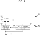
- FIG. 2 is a block diagram of a rail-to-ground voltage suppression system 1S according to the first embodiment of the present invention.
- the rail-to-ground voltage suppression system 1S for an electric railway includes a voltage control device 201 and a rail-to-ground voltage acquisition device 202.
- the voltage control device 201 connects the rail 104 and the ground electrode 106, and controls a voltage between the rail 104 and the ground electrode 106. Details of the voltage control device 201 will be described later.
- the rail-to-ground voltage acquisition device 202 acquires the voltage between the rail 104 and the ground electrode 106, and outputs it as a rail-to-ground voltage 211 to the voltage control device 201.
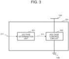
- FIG. 3 is a block diagram of the voltage control device 201 according to the first embodiment of the present invention.
- the voltage control device 201 includes a voltage determination unit 301 and a voltage control circuit 302.
- the voltage determination unit 301 receives the rail-to-ground voltage 211 and outputs a voltage control command value 311. Details of a process in the voltage determination unit 301 will be described later.
- the voltage control circuit 302 receives the voltage control command value 311, and controls the voltage between the rail 104 and the ground electrode 106.
- the voltage control circuit 302 includes a variable resistor having a function to feed back the voltage between the rail 104 and the ground electrode 106, and employs a method in which a resistance value of the variable resistor is controlled such that the voltage between the rail 104 and the ground electrode 106 has the voltage control command value 311.
- the voltage control circuit 302 only needs to have a system configuration that can control the voltage between the rail 104 and the ground electrode 106.
- the voltage control circuit 302 may include a bidirectional chopper that has a function to feed back a voltage, and employ a method to control an apparent resistance value by adjusting a conduction ratio of the chopper such that the voltage between the rail 104 and the ground electrode 106 has the voltage control command value 311.
- the bidirectional chopper is an example, and any device configured to bidirectionally step down a voltage may be employed.
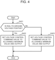
- FIG. 4 is a flowchart illustrating a process in the voltage determination unit 301 according to the first embodiment of the present invention. Execution of the process illustrated in FIG. 4 is triggered by detection of the deviation of the rail-to-ground voltage 211 from the allowable range by the voltage determination unit 301.
- Step S401 the voltage determination unit 301 determines the rail-to-ground voltage 211 to be positive or negative, advances the process to Step S402 in the case of being positive (Yes, in Step S401), and advances the process to Step S403 in the case of being negative (No, in Step S401).
- Step S402 the voltage determination unit 301 sets the voltage control command value 311 to an allowable maximum value (see FIG. 5 ) in the allowable range of the rail-to-ground voltage 211, and outputs it.
- Step S403 the voltage determination unit 301 sets the voltage control command value 311 to an allowable minimum value (see FIG. 5 ) in the allowable range of the rail-to-ground voltage 211, and outputs it.
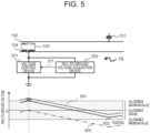
- FIG. 5 is a drawing for describing the effect of the first embodiment of the present invention.
- a dotted line 501 indicates the rail-to-ground voltage before activating the rail-to-ground voltage suppression system 1S.
- a solid line 502 indicates the rail-to-ground voltage in a state where the rail-to-ground voltage suppression system 1S is activated.
- a two-dot chain line 503 indicates the rail-to-ground voltage assuming that the VLD of the conventional technique is activated at the position of the voltage control device 201.
- the solid line 502 indicates that the reduction amount of the rail-to-ground voltage at the position of the rail-to-ground voltage suppression system 1S is reduced to be minimum and the rail-to-ground voltage is kept within the allowable range also at the position apart from the rail-to-ground voltage suppression system 1S.
- the deviation of the rail-to-ground voltage from the allowable range can be avoided at the position apart from the rail-to-ground voltage suppression system 1S.
- the example in which one pair of the voltage control device 201 and the rail-to-ground voltage acquisition device 202 is installed in the train line is indicated.
- a plurality of pairs can be installed to individually control the rail-to-ground voltage 211 at respective installation positions. For example, even when the rail-to-ground voltage simultaneously exceeds the allowable maximum value at one installation position and falls below the allowable minimum value at another installation position, the similar effect can be provided.
- FIG. 6 is a block diagram of a rail-to-ground voltage suppression system 2S according to the second embodiment of the present invention.
- the rail-to-ground voltage suppression system 2S includes a voltage control device 601 and a plurality of rail-to-ground voltage acquisition devices 202a, 202b, 202c, and 202d.
- the voltage control device 601 receives rail-to-ground voltages 211a, 211b, 211c, and 211d from the plurality of rail-to-ground voltage acquisition devices 202a, 202b, 202c, and 202d, respectively, and controls the voltage between the rail 104 and the ground electrode 106. Details of the voltage control device 601 will be described later.
- the rail-to-ground voltage acquisition devices 202a, 202b, 202c, and 202d are the same as the rail-to-ground voltage acquisition device 202 described in the first embodiment, thus omitting the description.
- FIG. 7 is a block diagram of the voltage control device 601 according to the second embodiment of the present invention.
- the voltage control device 601 includes a voltage determination unit 701 and a voltage control circuit 702.
- the voltage determination unit 701 receives the rail-to-ground voltages 211a, 211b, 211c, and 211d, and outputs the voltage control command value 311. Details of a process in the voltage determination unit 701 will be described later.
- the voltage control circuit 702 receives the voltage control command value 311 and controls an electric potential difference between the rail 104 and the ground electrode 106.
- the voltage control circuit 702 includes a converter configured to bidirectionally step up/down a voltage.
- the converter configured to bidirectionally step up/down a voltage is an example, and any device configured to bidirectionally step up/down a voltage may be employed.
- FIG. 8 is a flowchart illustrating a process in the voltage determination unit 701 according to the second embodiment of the present invention.
- the process illustrated in FIG. 8 is regularly executed.
- the voltage determination unit 701 determines whether any of the rail-to-ground voltages 211a, 211b, 211c, and 211d has exceeded the allowable maximum value in the allowable range or not.
- the voltage determination unit 701 advances the process to Step S803, and advances the process to Step S802 in the other case.
- Step S802 the voltage determination unit 701 determines whether any of the rail-to-ground voltages 211a, 211b, 211c, and 211d has fallen below the allowable minimum value in the allowable range or not. When any of the rail-to-ground voltages 211a, 211b, 211c, and 211d has fallen below the allowable minimum value in the allowable range (Yes, in S802), the voltage determination unit 701 advances the process to Step S804, and the process in the voltage determination unit 701 according to the second embodiment ends in the other case.
- Step S803 the voltage determination unit 701 calculates the voltage control command value 311 (voltage control command value V S ) based on a formula (1) below and outputs it.
- V S V D ⁇ V Max ⁇ V AlMax
- Step S804 the voltage determination unit 701 calculates the voltage control command value 311 (voltage control command value V S ) based on a formula (2) below and outputs it.
- V S V D + V AlMin ⁇ V Min
- Steps S801 and S803 While a process group of Steps S801 and S803 is executed with priority to a process group of Steps S802 and S804 in FIG. 8 , this should not be construed in a limiting sense. That is, the process group of Steps S802 and S804 may be executed with priority to the process group of Steps S801 and S803.
- FIG. 9 and FIG. 10 are drawings for describing the effect of the second embodiment of the present invention.
- the voltage control by the voltage control device 601 includes the following four patterns.
- FIG. 9 illustrates an example in which the sign of the rail-to-ground voltage at the position at which the rail-to-ground voltage deviates from the allowable range matches the sign of the rail-to-ground voltage at the voltage control device position.
- a dotted line 901 indicates the rail-to-ground voltage when the voltage control by the voltage control device 601 is not performed, and the rail-to-ground voltage at the position of the rail-to-ground voltage acquisition device 202b exceeds the allowable maximum value.
- a solid line 902 indicates the rail-to-ground voltage when a step-down control is performed in accordance with the control described in this embodiment, and the rail-to-ground voltage at the installation position of the rail-to-ground voltage acquisition device 202b is kept in the allowable range.
- the rail-to-ground voltage acquisition devices 202a, 202b, 202c, and 202d are installed at the positions apart from the voltage control device 601, and when the rail-to-ground voltage acquired by any of the rail-to-ground voltage acquisition devices deviates from the allowable range, the step-down control of the voltage of the voltage control device 601 is performed so as to keep the rail-to-ground voltage at the position of deviating from the allowable range in the allowable range. Accordingly, the rail-to-ground voltage in a wide range can be kept in the allowable range by one voltage control device.
- the pattern 3 is a pattern in which the pattern 1 has the inverted signs, the illustration and the description are omitted.
- FIG. 10 illustrates an example in which the sign of the rail-to-ground voltage at the position at which the rail-to-ground voltage deviates from the allowable range does not match the sign of the rail-to-ground voltage at the voltage control device position.
- a dotted line 1001 indicates the rail-to-ground voltage when the voltage control by the voltage control device 601 is not performed, and the rail-to-ground voltage at the position of the rail-to-ground voltage acquisition device 202b exceeds the allowable maximum value.
- a solid line 1002 indicates the rail-to-ground voltage when a step-up control in the negative direction is performed in accordance with the control described in this embodiment, and the rail-to-ground voltage of the rail-to-ground voltage acquisition device 202b is kept in the allowable range.
- the rail-to-ground voltage acquisition devices 202a, 202b, 202c, and 202d are installed at the positions apart from the voltage control device position, and further, the voltage control circuit 702 includes the converter configured to bidirectionally step up/down the voltage. This allows the reduction of the rail-to-ground voltage even when the sign of the rail-to-ground voltage at the position at which the rail-to-ground voltage deviates from the allowable range does not match the sign of the rail-to-ground voltage at the voltage control device position.
- the rail-to-ground voltage in the wider range can be kept in the allowable range by one voltage control device.
- the pattern 4 is a pattern in which in the pattern 2 has the inverted signs, the illustration and the description are omitted.
- the number of the rail-to-ground voltage acquisition devices is not limited thereto.
- the rail-to-ground voltage acquisition devices 202a, 202b, 202c, and 202d do not necessarily need to actually measure the rail-to-ground voltage, and for example, a configuration in which the rail-to-ground voltage is calculated to be acquired with a simulation model that calculates the rail-to-ground voltage from a train position, an electrical substation output power, and a train electric power may be employed.
- the rail-to-ground voltage can be continuously calculated, the deviation of the rail-to-ground voltage from the allowable range can be reduced without fail using the rail-to-ground voltage precisely acquired at low cost compared with the case of the rail-to-ground voltage acquisition by the measurement.
- the voltage control command value 311 is obtained by the process illustrated in FIG. 8 in this embodiment, the voltage control command value 311 may be determined by a feedback of the rail-to-ground voltage value at the position at which the rail-to-ground voltage deviates from the allowable range and performing a PID control so as to keep the rail-to-ground voltage value in the allowable range.
- FIG. 11 is a block diagram of a rail-to-ground voltage suppression system 3S according to the third embodiment of the present invention. Since the configuration other than a voltage control device 1101 is the same as the configuration illustrated in FIG. 6 of the second embodiment, the description will be omitted.
- the voltage control device 1101 receives rail-to-ground voltages 211a, 211b, 211c, and 211d from the plurality of rail-to-ground voltage acquisition devices 202a, 202b, 202c, and 202d, respectively, and controls the voltage between the rail 104 and the ground electrode 106. Details of the voltage control device 1101 will be described later.
- FIG. 12 is a block diagram of the voltage control device 1101 according to the third embodiment of the present invention.
- the voltage control device 1101 includes a voltage determination unit 1201 and the voltage control circuit 702. Since the configuration other than the voltage determination unit 1201 is the same as that of the voltage control device 601 of the second embodiment, the description will be omitted.
- the voltage determination unit 1201 receives the rail-to-ground voltages 211a, 211b, 211c, and 211d, and outputs the voltage control command value 311.
- FIG. 13 is a flowchart illustrating a process in the voltage determination unit 1201 according to the third embodiment of the present invention. The process illustrated in FIG. 13 is regularly executed.
- Step S1301 the voltage determination unit 1201 determines whether any of the rail-to-ground voltages 211a, 211b, 211c, and 211d has exceeded the allowable maximum value in the allowable range or not.
- the voltage determination unit 1201 advances the process to Step S1303, and advances the process to Step S1302 in the other case.
- Step S1302 the voltage determination unit 1201 determines whether any of the rail-to-ground voltages 211a, 211b, 211c, and 211d has fallen below the allowable minimum value in the allowable range or not. When any of the rail-to-ground voltages 211a, 211b, 211c, and 211d has fallen below the allowable minimum value in the allowable range (Yes, in S1302), the voltage determination unit 1201 advances the process to Step S1204, and the process in the voltage determination unit 1201 according to the third embodiment ends in the other case.
- Step S1303 the voltage determination unit 1201 calculates the voltage control command value 311 (voltage control command value V S ) based on a formula (3) below such that a difference between the maximum value and the allowable maximum value of the rail-to-ground voltage becomes the same as a difference between the minimum value and the allowable minimum value of the rail-to-ground voltage, and outputs it.
- V S V D ⁇ V Max ⁇ V TMax
- V TMax V AlMax ⁇ V AlMax ⁇ V AlMin ⁇ V Max ⁇ V Min / 2
- Step S1304 the voltage determination unit 1201 calculates the voltage control command value 311 (voltage control command value V S ) based on a formula (4) below such that the difference between the maximum value and the allowable maximum value of the rail-to-ground voltage becomes the same as the difference between the minimum value and the allowable minimum value of the rail-to-ground voltage, and outputs it.
- V S V D + V TMin ⁇ V AlMin
- V TMin V AlMin + V AlMax ⁇ V AlMin ⁇ V Max ⁇ V Min / 2
- FIG. 14 is a drawing for describing the effect of the third embodiment of the present invention.
- a dotted line 1401 indicates the rail-to-ground voltage when the voltage control by the voltage control device 1101 is not performed, and the rail-to-ground voltage at the position of the rail-to-ground voltage acquisition device 202b exceeds the allowable maximum value.
- a solid line 1402 indicates the rail-to-ground voltage when a step-down control is performed in accordance with the control described in this embodiment, and the rail-to-ground voltage of the rail-to-ground voltage acquisition device 202b is kept in the allowable range and further has a value smaller than the allowable maximum value.
- a difference d1 between the allowable maximum value and the rail-to-ground voltage 211b of the rail-to-ground voltage acquisition device 202b is equal to a difference d2 between the rail-to-ground voltage 211d of the rail-to-ground voltage acquisition device 202d and the allowable minimum value.
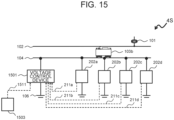
- FIG. 15 is a block diagram of a rail-to-ground voltage suppression system 4S according to the fourth embodiment of the present invention.
- the rail-to-ground voltage suppression system 4S includes a voltage control device 1501, the rail-to-ground voltage acquisition devices 202a, 202b, 202c, and 202d, and a protection target area setting unit 1503. Since the rail-to-ground voltage acquisition devices 202a, 202b, 202c, and 202d are the same as those illustrated in FIG. 6 of the second embodiment, the description will be omitted.
- the voltage control device 1501 receives rail-to-ground voltages 211a, 211b, 211c, and 211d from the plurality of rail-to-ground voltage acquisition devices 202a, 202b, 202c, and 202d.
- the voltage control device 1501 receives protection target area setting information 1511 from the protection target area setting unit 1503.
- the voltage control device 1501 controls the voltage between the rail 104 and the ground electrode 106 based on these inputs. Details of the voltage control device 1501 will be described later.
- the protection target area setting unit 1503 sets a position or a section to suppress the increase of the rail-to-ground voltage to a protection target area, and outputs the protection target area setting information 1511 to the voltage control device 1501.
- the protection target area is a position or a section set to the rail 104 to protect a human and the like from an electric shock by suppressing a rail-to-ground voltage average value to a predetermined value (for example, 0 V or a value of the predetermined value or less).
- FIG. 16 is a block diagram of the voltage control device 1501 according to the fourth embodiment of the present invention.
- the voltage control device 1501 includes a voltage determination unit 1601 and the voltage control circuit 702. Since the configuration other than the voltage determination unit 1601 is the same as that of the voltage control device 601 of the second embodiment, the description will be omitted.
- the voltage determination unit 1601 receives the rail-to-ground voltages 211a, 211b, 211c, and 211d and the protection target area setting information 1511, and outputs the voltage control command value 311.
- FIG. 16 is a flowchart illustrating a process in the voltage determination unit 1601 according to the fourth embodiment of the present invention. The process illustrated in FIG. 16 is regularly executed.
- Step S1701 the voltage determination unit 1601 determines whether any of the rail-to-ground voltages 211a, 211b, 211c, and 211d has exceeded the allowable maximum value or not.
- the voltage determination unit 1601 advances the process to Step S1703, and advances the process to Step S1702 in the other case.
- Step S1702 the voltage determination unit 1601 determines whether any of the rail-to-ground voltages 211a, 211b, 211c, and 211d has fallen below the allowable minimum value or not.
- the voltage determination unit 1601 advances the process to Step S1706, and the process in the voltage determination unit 1601 according to the fourth embodiment ends in the other case.
- Step S1703 the voltage determination unit 1601 determines whether a formula (5) below is satisfied or not.
- the voltage determination unit 1601 advances the process to Step S1704, and when the formula (5) below is not satisfied (No, in Step S1703), the voltage determination unit 1601 advances the process to Step S1705.
- Step S1704 is executed when Step S1703 is Yes, that is, a value obtained by subtracting the difference between the maximum value and the allowable maximum value of the rail-to-ground voltage from the rail-to-ground voltage average value of the protection target area set by the protection target area setting unit 1503 is negative.
- the rail-to-ground voltage decreased more than necessary causes the rail-to-ground voltage of the protection target area to become apart from 0 V to be small. That is, the absolute value of the rail-to-ground voltage increases.
- Step S1704 the voltage determination unit 1601 calculates the voltage control command value 311 (voltage control command value V S ) based on a formula (6) below so as to suppress the reduction amount of the rail-to-ground voltage to a minimum, and outputs it.
- V S V D ⁇ V Max ⁇ V AlMax
- Step S1705 is executed when Step S1703 is No, that is, the value obtained by subtracting the difference between the maximum value and the allowable maximum value of the rail-to-ground voltage from the rail-to-ground voltage average value of the protection target area set by the protection target area setting unit 1503 is positive.
- the voltage determination unit 1601 calculates the voltage control command value V S using a formula (7) below so as to make the rail-to-ground voltage average value of the protection target area 0 V, and outputs it.
- V S V D ⁇ V H
- Step S1706 the voltage determination unit 1601 determines whether a formula (8) below is satisfied or not.
- the voltage determination unit 1601 advances the process to Step S1707, and when the formula (8) below is not satisfied (No, in Step S1706), the voltage determination unit 1601 advances the process to Step S1708.
- Step S1707 is executed when Step S1706 is Yes, that is, a value obtained by adding the difference between the allowable minimum value and the minimum value of the rail-to-ground voltage to the rail-to-ground voltage average value of the protection target area set by the protection target area setting unit 1503 is 0 or more.
- the rail-to-ground voltage increased more than necessary causes the rail-to-ground voltage of the protection target area to become apart from 0 V to be large. That is, the absolute value of the rail-to-ground voltage increases. Therefore, in Step S1707, the voltage determination unit 1601 calculates the voltage control command value V S based on a formula (9) below so as to suppress the increased amount of the rail-to-ground voltage to a minimum, and outputs it.
- V S V D + V AlMin ⁇ V Min
- Step S1708 is executed when Step S1706 is No, that is, a value obtained by adding the difference between the allowable minimum value and the minimum value of the rail-to-ground voltage to the rail-to-ground voltage average value of the protection target area set by the protection target area setting unit 1503 is negative.
- the voltage determination unit 1601 calculates the voltage control command value V S based on a formula (10) below so as to make the rail-to-ground voltage average value of the protection target area 0 V, and outputs it.
- V S V D + V H
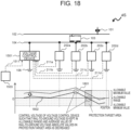
- FIG. 18 is a drawing for describing the effect of the fourth embodiment of the present invention.
- a dotted line 1801 indicates the rail-to-ground voltage when the voltage control by the voltage control device 1501 is not performed, and the rail-to-ground voltage at the position of the rail-to-ground voltage acquisition device 202b exceeds the allowable maximum value.
- a solid line 1802 indicates the rail-to-ground voltage when a step-down control is performed in accordance with the control described in this embodiment, and the rail-to-ground voltage of the rail-to-ground voltage acquisition device 202b is kept in the allowable range, and further, the rail-to-ground voltage average value of the protection target area is 0 V.
- the rail-to-ground voltage of the protection target area can be decreased while keeping the rail-to-ground voltage in the allowable range, thereby allowing more reducing the risk of an electric shock due to the rail-to-ground voltage.
- the control may be performed in a manner in which a priority order is given to the protection target area, and the rail-to-ground voltage average value of the protection target area having the high priority order is suppressed to a predetermined value.
- the control may be performed in a manner in which a sum of the rail-to-ground voltage average values of the plurality of protection target areas is suppressed to a predetermined value.
- control may be performed in a manner in which the rail-to-ground voltage of the protection target area is suppressed by decreasing the maximum value, the minimum value, or the like not limiting to the average value.
- a plurality of the voltage control devices may be disposed in the train line.
- the voltage control device at the position closest to a rail-to-ground voltage acquisition device having the rail-to-ground voltage deviating from the allowable range controls the rail-to-ground voltage at the installation position of itself, thus allowing to avoid competing in the control.
- the voltage control device of the rail-to-ground voltage having the sign the same as that of the rail-to-ground voltage deviating from the allowable range and having the maximum absolute value controls the rail-to-ground voltage at the installation position of itself, thereby maximally ensuring the reduction range of the absolute value of the rail-to-ground voltage.
- the difference between the maximum value and the minimum value of the rail-to-ground voltages detected by the plurality of rail-to-ground voltage acquisition devices is significantly large to be a predetermined value or more, and the minimum value is not kept in the allowable range when the maximum value is suppressed to the allowable maximum value. Similarly, it may occur that the maximum value is not kept in the allowable range when the minimum value is suppressed to the allowable minimum value.
- the voltage control device of the rail-to-ground voltages having the absolute values in both positive and negative directions that are each the predetermined value (for example, the maximum value) or more controls the rail-to-ground voltage at the installation position of itself, thereby allowing keeping the maximum value and the minimum value of the rail-to-ground voltages in the allowable range.
Landscapes
- Engineering & Computer Science (AREA)
- Mechanical Engineering (AREA)
- Emergency Protection Circuit Devices (AREA)
- Train Traffic Observation, Control, And Security (AREA)
- Electric Propulsion And Braking For Vehicles (AREA)
Claims (7)
- Schiene-zu-Erde-Spannungsunterdrückungssystem für eine elektrische Eisenbahn, das Folgendes umfasst:eine oder eine Vielzahl von Schiene-zu-Erde-Spannungserfassungsvorrichtungen (202), die jeweils eine Schiene-zu-Erde-Spannung (211) erfassen; undeine Spannungssteuerungsvorrichtung (201, 601, 1101, 1501), die eine Schiene (104) und eine Erdungselektrode (106) verbindet,dadurch gekennzeichnet, dass:die Spannungssteuerungsvorrichtung (201, 601, 1101, 1501) eine Spannungsbestimmungseinheit (301, 701, 1201, 1601) umfasst, welche die Schiene-zu-Erde-Spannung (211) empfängt und einen Spannungssteuerungsbefehlswert (311) ausgibt, und außerdem einen Spannungssteuerkreis (302, 702) umfasst, der den Spannungssteuerungsbefehlswert empfängt und die Spannung zwischen der Schiene und der Erdungselektrode steuert, wobei der Spannungssteuerkreis eine veränderliche Widerstandsvorrichtung umfasst, die ausgelegt ist, um die Spannung zwischen der Schiene und der Erdungselektrode zurückzumelden und einen tatsächlichen oder scheinbaren Widerstandswert der veränderlichen Widerstandsvorrichtung steuert, sodass die Spannung zwischen der Schiene und der Erdungselektrode den Spannungssteuerungsbefehlswert aufweist, wobeiwenn die durch eine der Schiene-zu-Erde-Spannungserfassungsvorrichtungen (202) an einer Installationsposition der Schiene-zu-Erde-Spannungserfassungsvorrichtung erfasste Schiene-zu-Erde-Spannung (211) von einem zulässigen Bereich abweicht, die Spannungssteuerungsvorrichtung (201, 601, 1101, 1501) die Schiene-zu-Erde-Spannung an der Installationsposition der Spannungssteuerungsvorrichtung durch Verbinden der Schiene (104) und der Erdungselektrode (106), die der durch die Schiene-zu-Erde-Spannungsvorrichtung erfassten Schiene-zu-Erde-Spannung entspricht, steuert, um die Schiene-zu-Erde-Spannung im zulässigen Bereich zu halten.
- Schiene-zu-Erde-Spannungsunterdrückungssystem nach Anspruch 1, das weiters Folgendes umfasst:eine Schutzzielbereichseinstellungseinheit (1503), die einen Schutzzielbereich auf der Schiene einstellt, wobei der Schutzzielbereich ein Zielbereich ist, in dem die Schiene-zu-Erde-Spannung unterdrückt wird, wobeiwenn die durch eine der Schiene-zu-Erde-Spannungserfassungsvorrichtungen (202) an der Installationsposition der Schiene-zu-Erde-Spannungserfassungsvorrichtung erfasste Schiene-zu-Erde-Spannung vom zulässigen Bereich abweicht, die Spannungssteuerungsvorrichtung (1501) die Schiene-zu-Erde-Spannung an der Installationsposition der Spannungssteuerungsvorrichtung steuert, um die Schiene-zu-Erde-Spannung des Schutzzielbereichs auf einem zulässigen Wert zu halten.
- Schiene-zu-Erde-Spannungsunterdrückungssystem nach Anspruch 2, wobeidie Schutzzielbereichseinstellungseinheit (1503) eine Vielzahl der Schutzzielbereiche unter Hinzufügung einer Prioritätsreihenfolge einstellt undwenn die durch eine der Schiene-zu-Erde-Spannungserfassungsvorrichtungen (202) an der Installationsposition der Schiene-zu-Erde-Spannungserfassungsvorrichtung erfasste Schiene-zu-Erde-Spannung vom zulässigen Bereich abweicht, die Spannungssteuerungsvorrichtung (1501) die Schiene-zu-Erde-Spannung an der Installationsposition der Spannungssteuerungsvorrichtung steuert, um die Schiene-zu-Erde-Spannungen der Schutzzielbereiche entsprechend der Prioritätsreihenfolge zu unterdrücken.
- Schiene-zu-Erde-Spannungsunterdrückungssystem nach Anspruch 2, wobeidie Schutzzielbereichseinstellungseinheit (1503) eine Vielzahl der Schutzzielbereiche einstellt undwenn die durch eine der Schiene-zu-Erde-Spannungserfassungsvorrichtungen (202) an der Installationsposition der Schiene-zu-Erde-Spannungserfassungsvorrichtung erfasste Schiene-zu-Erde-Spannung vom zulässigen Bereich abweicht, die Spannungssteuerungsvorrichtung (1501) die Schiene-zu-Erde-Spannung an der Installationsposition der Spannungssteuerungsvorrichtung steuert, um die Schiene-zu-Erde-Spannungen der Vielzahl von Schutzzielbereichen zu unterdrücken.
- Schiene-zu-Erde-Spannungsunterdrückungssystem nach einem der Ansprüche 1 bis 4, das Folgendes umfasst:
eine Vielzahl der Spannungssteuerungsvorrichtungen (201, 601, 1101, 1501), wobei:
wenn die durch eine der Schiene-zu-Erde-Spannungserfassungsvorrichtungen (202) an der Installationsposition der Schiene-zu-Erde-Spannungserfassungsvorrichtung erfasste Schiene-zu-Erde-Spannung vom zulässigen Bereich abweicht, die Spannungssteuerungsvorrichtung (201, 601, 1101, 1501) an der am nächsten zur Schiene-zu-Erde-Spannungserfassungsvorrichtung gelegenen Installationsposition die Schiene-zu-Erde-Spannung an der Installationsposition der Spannungssteuerungsvorrichtung steuert. - Schiene-zu-Erde-Spannungsunterdrückungssystem nach einem der Ansprüche 1 bis 4, die Folgendes umfasst:
eine Vielzahl der Spannungssteuerungsvorrichtungen (201, 601, 1101, 1501), wobei:
wenn die durch eine der Schiene-zu-Erde-Spannungserfassungsvorrichtungen (202) an der Installationsposition der Schiene-zu-Erde-Spannungserfassungsvorrichtung erfasste Schiene-zu-Erde-Spannung vom zulässigen Bereich abweicht, die Spannungssteuerungsvorrichtung (201, 601, 1101, 1501) der Schiene-zu-Erde-Spannung mit einem identischen Vorzeichen wie das Vorzeichen der Schiene-zu-Erde-Spannung und mit einem maximalen Absolutwert die Schiene-zu-Erde-Spannung an der Installationsposition der Spannungssteuerungsvorrichtung steuert. - Schiene-zu-Erde-Spannungsunterdrückungssystem nach einem der Ansprüche 1 bis 4, das Folgendes umfasst:
eine Vielzahl der Spannungssteuerungsvorrichtungen (201, 601, 1101, 1501), wobei:
wenn die durch eine der Schiene-zu-Erde-Spannungserfassungsvorrichtungen (202) an der Installationsposition der Schiene-zu-Erde-Spannungserfassungsvorrichtung erfasste Schiene-zu-Erde-Spannung vom zulässigen Bereich abweicht und die Differenz zwischen dem Maximalwert und Minimalwert der durch die Vielzahl von Schiene-zu-Erde-Spannungserfassungsvorrichtungen (201, 601, 1101, 1501) erfassten Schiene-zu-Erde-Spannungen ein vorbestimmter Wert oder mehr ist, die Spannungssteuerungsvorrichtung der Schiene-zu-Erde-Spannungen mit Absolutwerten sowohl in die positive als auch in die negative Richtung, die jeweils ein vorbestimmter Wert oder mehr sind, die Schiene-zu-Erde-Spannung an der Installationsposition der Spannungssteuerungsvorrichtung steuert, um den Maximalwert und den Minimalwert im zulässigen Bereich zu halten.
Applications Claiming Priority (1)
| Application Number | Priority Date | Filing Date | Title |
|---|---|---|---|
| JP2020043606A JP7396938B2 (ja) | 2020-03-13 | 2020-03-13 | レール対地電圧抑制システム |
Publications (2)
| Publication Number | Publication Date |
|---|---|
| EP3885183A1 EP3885183A1 (de) | 2021-09-29 |
| EP3885183B1 true EP3885183B1 (de) | 2025-01-22 |
Family
ID=74874668
Family Applications (1)
| Application Number | Title | Priority Date | Filing Date |
|---|---|---|---|
| EP21162501.7A Active EP3885183B1 (de) | 2020-03-13 | 2021-03-15 | Schiene-zu-boden-spannungsunterdrückungssystem |
Country Status (2)
| Country | Link |
|---|---|
| EP (1) | EP3885183B1 (de) |
| JP (1) | JP7396938B2 (de) |
Families Citing this family (4)
| Publication number | Priority date | Publication date | Assignee | Title |
|---|---|---|---|---|
| JP7759244B2 (ja) * | 2021-12-01 | 2025-10-23 | 株式会社日立製作所 | 接地抵抗劣化位置推定装置及びその方法 |
| CN117200133B (zh) * | 2022-05-31 | 2025-01-14 | 比亚迪股份有限公司 | 一种轨交车辆及其的漏电保护系统和方法 |
| CN116853080B (zh) * | 2023-07-31 | 2024-04-09 | 清华大学 | 基于城轨柔直系统全线轨电位的ovpd主动选点动作方法 |
| EP4516561A1 (de) * | 2023-09-01 | 2025-03-05 | HYPERION Verwaltung GmbH | Verfahrbare elektrische umform-station |
Family Cites Families (3)
| Publication number | Priority date | Publication date | Assignee | Title |
|---|---|---|---|---|
| JPS52116512A (en) * | 1976-03-26 | 1977-09-30 | Kinki Nippon Railway | Electrolytic corrosion prevention device employing pressureegrounded electrode |
| JP6220209B2 (ja) * | 2013-09-30 | 2017-10-25 | 株式会社東芝 | 直流き電保護制御システム |
| JP6299920B1 (ja) * | 2017-04-26 | 2018-03-28 | 株式会社明電舎 | 直流電気鉄道の直流地絡検出システムおよび直流地絡検出方法 |
-
2020
- 2020-03-13 JP JP2020043606A patent/JP7396938B2/ja active Active
-
2021
- 2021-03-15 EP EP21162501.7A patent/EP3885183B1/de active Active
Also Published As
| Publication number | Publication date |
|---|---|
| JP2021145501A (ja) | 2021-09-24 |
| JP7396938B2 (ja) | 2023-12-12 |
| EP3885183A1 (de) | 2021-09-29 |
Similar Documents
| Publication | Publication Date | Title |
|---|---|---|
| EP3885183B1 (de) | Schiene-zu-boden-spannungsunterdrückungssystem | |
| TWI466406B (zh) | Solar power generation system and power supply system | |
| CN106470867B (zh) | 车辆用控制装置 | |
| EP2648322B1 (de) | Überbrückungsschaltung bei Stromunterbrechung | |
| CA2787604A1 (en) | Power distribution in aircraft | |
| CN105337335B (zh) | 针对多个电池匹配放电结束的系统和方法 | |
| GB2563839A (en) | System and method for limiting currents in a power distribution system | |
| US10122180B2 (en) | Bus conditioner for an aircraft power system | |
| US10840729B2 (en) | Method and system for operating a DC-DC converter of an electrical system to distribute a load | |
| JP6517857B2 (ja) | 電圧調整機器の電圧制御装置およびその電圧制御方法 | |
| CA2412154C (en) | System and method for monitoring battery equalization | |
| US9748832B2 (en) | Power converter and power conversion method | |
| US11476661B2 (en) | Device for controlling a terminal for the compensation of a voltage disturbance | |
| US20120106009A1 (en) | Shunt Regulator at Excitation Output of Generator Control Unit for Overvoltage Protection | |
| EP3346570B1 (de) | Stromversorgungsvorrichtung | |
| DE102023100505A1 (de) | Verfahren und System zum Schützen einer Bordbatterie-Ladeeinrichtung vor vorübergehenden Unterbrechungen in einem Hochspannungsnetz | |
| WO2019003867A1 (ja) | 車載用電源回路及び車載用電源装置 | |
| KR20230068618A (ko) | 저전압 직류 배전 계통의 보호 관리 시스템 및 보호 관리 방법 | |
| JP6646790B1 (ja) | 直流電力ネットワークシステム並びにdc/dcコンバータ装置及びその制御方法 | |
| EP3002864A1 (de) | Stromwandler und steuerungsverfahren | |
| US12525880B2 (en) | Load current distribution adjustment device, load current distribution adjustment method, and load current distribution adjustment program of power conversion device for energy storage system | |
| US20240359590A1 (en) | Power supply | |
| KR100258484B1 (ko) | 배전선의 보호장치 | |
| JP2008193834A (ja) | 静止形無停電電源装置の電圧制御装置及び電圧制御方法 | |
| US11762447B2 (en) | Power supply with boost stage to improve ride through performance |
Legal Events
| Date | Code | Title | Description |
|---|---|---|---|
| PUAI | Public reference made under article 153(3) epc to a published international application that has entered the european phase |
Free format text: ORIGINAL CODE: 0009012 |
|
| STAA | Information on the status of an ep patent application or granted ep patent |
Free format text: STATUS: REQUEST FOR EXAMINATION WAS MADE |
|
| 17P | Request for examination filed |
Effective date: 20210315 |
|
| AK | Designated contracting states |
Kind code of ref document: A1 Designated state(s): AL AT BE BG CH CY CZ DE DK EE ES FI FR GB GR HR HU IE IS IT LI LT LU LV MC MK MT NL NO PL PT RO RS SE SI SK SM TR |
|
| GRAP | Despatch of communication of intention to grant a patent |
Free format text: ORIGINAL CODE: EPIDOSNIGR1 |
|
| STAA | Information on the status of an ep patent application or granted ep patent |
Free format text: STATUS: GRANT OF PATENT IS INTENDED |
|
| INTG | Intention to grant announced |
Effective date: 20240819 |
|
| GRAS | Grant fee paid |
Free format text: ORIGINAL CODE: EPIDOSNIGR3 |
|
| GRAA | (expected) grant |
Free format text: ORIGINAL CODE: 0009210 |
|
| STAA | Information on the status of an ep patent application or granted ep patent |
Free format text: STATUS: THE PATENT HAS BEEN GRANTED |
|
| AK | Designated contracting states |
Kind code of ref document: B1 Designated state(s): AL AT BE BG CH CY CZ DE DK EE ES FI FR GB GR HR HU IE IS IT LI LT LU LV MC MK MT NL NO PL PT RO RS SE SI SK SM TR |
|
| REG | Reference to a national code |
Ref country code: GB Ref legal event code: FG4D |
|
| REG | Reference to a national code |
Ref country code: CH Ref legal event code: EP |
|
| REG | Reference to a national code |
Ref country code: IE Ref legal event code: FG4D |
|
| REG | Reference to a national code |
Ref country code: DE Ref legal event code: R096 Ref document number: 602021025037 Country of ref document: DE |
|
| PGFP | Annual fee paid to national office [announced via postgrant information from national office to epo] |
Ref country code: AT Payment date: 20250417 Year of fee payment: 5 |
|
| REG | Reference to a national code |
Ref country code: NL Ref legal event code: MP Effective date: 20250122 |
|
| PG25 | Lapsed in a contracting state [announced via postgrant information from national office to epo] |
Ref country code: NL Free format text: LAPSE BECAUSE OF FAILURE TO SUBMIT A TRANSLATION OF THE DESCRIPTION OR TO PAY THE FEE WITHIN THE PRESCRIBED TIME-LIMIT Effective date: 20250122 |
|
| PG25 | Lapsed in a contracting state [announced via postgrant information from national office to epo] |
Ref country code: RS Free format text: LAPSE BECAUSE OF FAILURE TO SUBMIT A TRANSLATION OF THE DESCRIPTION OR TO PAY THE FEE WITHIN THE PRESCRIBED TIME-LIMIT Effective date: 20250422 |
|
| PG25 | Lapsed in a contracting state [announced via postgrant information from national office to epo] |
Ref country code: FI Free format text: LAPSE BECAUSE OF FAILURE TO SUBMIT A TRANSLATION OF THE DESCRIPTION OR TO PAY THE FEE WITHIN THE PRESCRIBED TIME-LIMIT Effective date: 20250122 |
|
| PG25 | Lapsed in a contracting state [announced via postgrant information from national office to epo] |
Ref country code: PL Free format text: LAPSE BECAUSE OF FAILURE TO SUBMIT A TRANSLATION OF THE DESCRIPTION OR TO PAY THE FEE WITHIN THE PRESCRIBED TIME-LIMIT Effective date: 20250122 |
|
| PG25 | Lapsed in a contracting state [announced via postgrant information from national office to epo] |
Ref country code: ES Free format text: LAPSE BECAUSE OF FAILURE TO SUBMIT A TRANSLATION OF THE DESCRIPTION OR TO PAY THE FEE WITHIN THE PRESCRIBED TIME-LIMIT Effective date: 20250122 |
|
| REG | Reference to a national code |
Ref country code: LT Ref legal event code: MG9D |
|
| PG25 | Lapsed in a contracting state [announced via postgrant information from national office to epo] |
Ref country code: NO Free format text: LAPSE BECAUSE OF FAILURE TO SUBMIT A TRANSLATION OF THE DESCRIPTION OR TO PAY THE FEE WITHIN THE PRESCRIBED TIME-LIMIT Effective date: 20250422 Ref country code: IS Free format text: LAPSE BECAUSE OF FAILURE TO SUBMIT A TRANSLATION OF THE DESCRIPTION OR TO PAY THE FEE WITHIN THE PRESCRIBED TIME-LIMIT Effective date: 20250522 |
|
| REG | Reference to a national code |
Ref country code: AT Ref legal event code: MK05 Ref document number: 1761239 Country of ref document: AT Kind code of ref document: T Effective date: 20250122 |
|
| PG25 | Lapsed in a contracting state [announced via postgrant information from national office to epo] |
Ref country code: HR Free format text: LAPSE BECAUSE OF FAILURE TO SUBMIT A TRANSLATION OF THE DESCRIPTION OR TO PAY THE FEE WITHIN THE PRESCRIBED TIME-LIMIT Effective date: 20250122 |
|
| PG25 | Lapsed in a contracting state [announced via postgrant information from national office to epo] |
Ref country code: LV Free format text: LAPSE BECAUSE OF FAILURE TO SUBMIT A TRANSLATION OF THE DESCRIPTION OR TO PAY THE FEE WITHIN THE PRESCRIBED TIME-LIMIT Effective date: 20250122 Ref country code: PT Free format text: LAPSE BECAUSE OF FAILURE TO SUBMIT A TRANSLATION OF THE DESCRIPTION OR TO PAY THE FEE WITHIN THE PRESCRIBED TIME-LIMIT Effective date: 20250522 |
|
| PG25 | Lapsed in a contracting state [announced via postgrant information from national office to epo] |
Ref country code: BG Free format text: LAPSE BECAUSE OF FAILURE TO SUBMIT A TRANSLATION OF THE DESCRIPTION OR TO PAY THE FEE WITHIN THE PRESCRIBED TIME-LIMIT Effective date: 20250122 Ref country code: GR Free format text: LAPSE BECAUSE OF FAILURE TO SUBMIT A TRANSLATION OF THE DESCRIPTION OR TO PAY THE FEE WITHIN THE PRESCRIBED TIME-LIMIT Effective date: 20250423 |
|
| PG25 | Lapsed in a contracting state [announced via postgrant information from national office to epo] |
Ref country code: AT Free format text: LAPSE BECAUSE OF FAILURE TO SUBMIT A TRANSLATION OF THE DESCRIPTION OR TO PAY THE FEE WITHIN THE PRESCRIBED TIME-LIMIT Effective date: 20250122 |
|
| PG25 | Lapsed in a contracting state [announced via postgrant information from national office to epo] |
Ref country code: SE Free format text: LAPSE BECAUSE OF FAILURE TO SUBMIT A TRANSLATION OF THE DESCRIPTION OR TO PAY THE FEE WITHIN THE PRESCRIBED TIME-LIMIT Effective date: 20250122 |
|
| PG25 | Lapsed in a contracting state [announced via postgrant information from national office to epo] |
Ref country code: SM Free format text: LAPSE BECAUSE OF FAILURE TO SUBMIT A TRANSLATION OF THE DESCRIPTION OR TO PAY THE FEE WITHIN THE PRESCRIBED TIME-LIMIT Effective date: 20250122 |
|
| PG25 | Lapsed in a contracting state [announced via postgrant information from national office to epo] |
Ref country code: DK Free format text: LAPSE BECAUSE OF FAILURE TO SUBMIT A TRANSLATION OF THE DESCRIPTION OR TO PAY THE FEE WITHIN THE PRESCRIBED TIME-LIMIT Effective date: 20250122 |
|
| PG25 | Lapsed in a contracting state [announced via postgrant information from national office to epo] |
Ref country code: MC Free format text: LAPSE BECAUSE OF FAILURE TO SUBMIT A TRANSLATION OF THE DESCRIPTION OR TO PAY THE FEE WITHIN THE PRESCRIBED TIME-LIMIT Effective date: 20250122 |
|
| PG25 | Lapsed in a contracting state [announced via postgrant information from national office to epo] |
Ref country code: CZ Free format text: LAPSE BECAUSE OF FAILURE TO SUBMIT A TRANSLATION OF THE DESCRIPTION OR TO PAY THE FEE WITHIN THE PRESCRIBED TIME-LIMIT Effective date: 20250122 Ref country code: EE Free format text: LAPSE BECAUSE OF FAILURE TO SUBMIT A TRANSLATION OF THE DESCRIPTION OR TO PAY THE FEE WITHIN THE PRESCRIBED TIME-LIMIT Effective date: 20250122 |
|
| REG | Reference to a national code |
Ref country code: DE Ref legal event code: R097 Ref document number: 602021025037 Country of ref document: DE |
|
| PG25 | Lapsed in a contracting state [announced via postgrant information from national office to epo] |
Ref country code: RO Free format text: LAPSE BECAUSE OF FAILURE TO SUBMIT A TRANSLATION OF THE DESCRIPTION OR TO PAY THE FEE WITHIN THE PRESCRIBED TIME-LIMIT Effective date: 20250122 |
|
| REG | Reference to a national code |
Ref country code: CH Ref legal event code: H13 Free format text: ST27 STATUS EVENT CODE: U-0-0-H10-H13 (AS PROVIDED BY THE NATIONAL OFFICE) Effective date: 20251024 |
|
| PG25 | Lapsed in a contracting state [announced via postgrant information from national office to epo] |
Ref country code: SK Free format text: LAPSE BECAUSE OF FAILURE TO SUBMIT A TRANSLATION OF THE DESCRIPTION OR TO PAY THE FEE WITHIN THE PRESCRIBED TIME-LIMIT Effective date: 20250122 |
|
| PG25 | Lapsed in a contracting state [announced via postgrant information from national office to epo] |
Ref country code: LU Free format text: LAPSE BECAUSE OF NON-PAYMENT OF DUE FEES Effective date: 20250315 |
|
| PLBE | No opposition filed within time limit |
Free format text: ORIGINAL CODE: 0009261 |
|
| STAA | Information on the status of an ep patent application or granted ep patent |
Free format text: STATUS: NO OPPOSITION FILED WITHIN TIME LIMIT |
|
| REG | Reference to a national code |
Ref country code: BE Ref legal event code: MM Effective date: 20250331 |
|
| 26N | No opposition filed |
Effective date: 20251023 |
|
| PG25 | Lapsed in a contracting state [announced via postgrant information from national office to epo] |
Ref country code: BE Free format text: LAPSE BECAUSE OF NON-PAYMENT OF DUE FEES Effective date: 20250331 |
|
| PG25 | Lapsed in a contracting state [announced via postgrant information from national office to epo] |
Ref country code: CH Free format text: LAPSE BECAUSE OF NON-PAYMENT OF DUE FEES Effective date: 20250331 |
|
| PG25 | Lapsed in a contracting state [announced via postgrant information from national office to epo] |
Ref country code: IE Free format text: LAPSE BECAUSE OF NON-PAYMENT OF DUE FEES Effective date: 20250315 |
|
| PGFP | Annual fee paid to national office [announced via postgrant information from national office to epo] |
Ref country code: GB Payment date: 20260317 Year of fee payment: 6 |
|
| PGFP | Annual fee paid to national office [announced via postgrant information from national office to epo] |
Ref country code: DE Payment date: 20260317 Year of fee payment: 6 |
|
| PGFP | Annual fee paid to national office [announced via postgrant information from national office to epo] |
Ref country code: IT Payment date: 20260319 Year of fee payment: 6 |
|
| PGFP | Annual fee paid to national office [announced via postgrant information from national office to epo] |
Ref country code: FR Payment date: 20260319 Year of fee payment: 6 |