EP3882086A1 - Panneau sensoriel pour la détection d'un impact sur un véhicule - Google Patents
Panneau sensoriel pour la détection d'un impact sur un véhicule Download PDFInfo
- Publication number
- EP3882086A1 EP3882086A1 EP21163546.1A EP21163546A EP3882086A1 EP 3882086 A1 EP3882086 A1 EP 3882086A1 EP 21163546 A EP21163546 A EP 21163546A EP 3882086 A1 EP3882086 A1 EP 3882086A1
- Authority
- EP
- European Patent Office
- Prior art keywords
- panel
- filament
- vehicle
- panel according
- respect
- Prior art date
- Legal status (The legal status is an assumption and is not a legal conclusion. Google has not performed a legal analysis and makes no representation as to the accuracy of the status listed.)
- Pending
Links
Images


Classifications
-
- B—PERFORMING OPERATIONS; TRANSPORTING
- B60—VEHICLES IN GENERAL
- B60R—VEHICLES, VEHICLE FITTINGS, OR VEHICLE PARTS, NOT OTHERWISE PROVIDED FOR
- B60R16/00—Electric or fluid circuits specially adapted for vehicles and not otherwise provided for; Arrangement of elements of electric or fluid circuits specially adapted for vehicles and not otherwise provided for
- B60R16/02—Electric or fluid circuits specially adapted for vehicles and not otherwise provided for; Arrangement of elements of electric or fluid circuits specially adapted for vehicles and not otherwise provided for electric constitutive elements
- B60R16/023—Electric or fluid circuits specially adapted for vehicles and not otherwise provided for; Arrangement of elements of electric or fluid circuits specially adapted for vehicles and not otherwise provided for electric constitutive elements for transmission of signals between vehicle parts or subsystems
- B60R16/0231—Circuits relating to the driving or the functioning of the vehicle
- B60R16/0232—Circuits relating to the driving or the functioning of the vehicle for measuring vehicle parameters and indicating critical, abnormal or dangerous conditions
- B60R16/0234—Circuits relating to the driving or the functioning of the vehicle for measuring vehicle parameters and indicating critical, abnormal or dangerous conditions related to maintenance or repairing of vehicles
Definitions
- the present invention relates to a vehicle panel, such as for example a vehicle body panel, in particular of a hybrid, electric or alternative-powered vehicle such as a gas- or hydrogen-powered vehicle or in general any other vehicle requiring the interruption of an electric circuit following its mechanical breakage.
- a vehicle panel such as for example a vehicle body panel, in particular of a hybrid, electric or alternative-powered vehicle such as a gas- or hydrogen-powered vehicle or in general any other vehicle requiring the interruption of an electric circuit following its mechanical breakage.
- Vehicles in particular electric or hybrid vehicles, comprise functional elements such as parts of electrical equipment, for example, high voltage cables or batteries used to provide adequate energy to electric motors that allow the vehicle to be driven.
- An example of such electrical parts of use may be represented by the so-called HVIL (High Voltage Interlock) or interlock circuit.
- protection systems configured to insulate the above-mentioned functional elements, i.e., for example, to insulate the circuits connected to the above-mentioned electrical equipment parts, such as the HVIL circuit, so as to prevent possible electric shock to users.
- An example of such a protection system is an opening signal generated by the impact signal which allows the operation of the air-bag system.
- this signal may be incorrectly generated or may not be generated at all due to a low-impulse impact which, however, is capable of causing significant damage to the vehicle.
- the object of the present invention is to meet the above requirements in an optimized and cost-effective manner.
- the reference number 1 indicates a vehicle as a whole, in the non-limiting example illustrated herein a Light Commercial Vehicle, LCV, comprising, as is known, a frame (not shown for simplicity) and a plurality of panels 2 defining the body of the said vehicle 1.
- LCV Light Commercial Vehicle
- the vehicle 1 also comprises at least one air-bag system 3 of a known type and configured to expand and cushion impacts that may potentially cause damage to the driver or passenger.
- the vehicle 1 further comprises an electronic unit 4 configured to control a plurality of vehicle systems, including the above-mentioned air-bag system 3 and functional elements, not shown and configured to allow the operation of the vehicle, such as high voltage electrical equipment parts or control valves connected to the alternative fuel supply and distribution systems on board the vehicle.
- an electronic unit 4 configured to control a plurality of vehicle systems, including the above-mentioned air-bag system 3 and functional elements, not shown and configured to allow the operation of the vehicle, such as high voltage electrical equipment parts or control valves connected to the alternative fuel supply and distribution systems on board the vehicle.
- Figure 2 shows a panel 2 according to a first embodiment of the invention comprising a body defining any substantially flat shape, i.e., with two dimensions much larger than the thickness of the said body.
- a parallelepiped portion is shown, for example, a body portion made of any shape and material, for example plastic.
- the panel 2 comprises a filament 5 made of electrically conductive material carried by the panel 2 and configured to break in case of impact and fracture of the panel 2.
- the filament 5 made of electrically conductive material is incorporated inside the body of the panel 2 so that it is not exposed to atmospheric agents and possible mechanical wear or abrasion. Even more advantageously, it is embedded in a plane corresponding to a neutral centre plane of the panel 2.
- Neutral plane refers to the plane in which the bending stresses on the panel 2 are the lowest (theoretically zero) with respect to a bending load imparted thereon.
- the filament 5 made of electrically conductive material enters through a first opening 6 inside the body of the panel 2 and exits therefrom through an opening 7 formed therein.
- the filament 5 made of electrically conductive material defines a path along the panel 2 so that it extends by at least twice the largest dimension of the panel 2.
- the filament 5 made of electrically conductive material defines a path extending far beyond twice the largest dimension of the panel 2, thereby providing a complex path to cover most of the surface defined by the panel 2.
- the filament 5 made of electrically conductive material defines a plurality of coils 5a parallel to the larger side of the panel 2.
- the plurality of coils 5a is embedded within the panel 2 between the first opening 6 and the second opening 7, which are positioned one below the other, respectively, and formed on the smaller edge of the panel 2.
- the path of the filament 5 made of electrically conductive material inside the panel 2 defines a "fork" shape due to the plurality of coils 5a connected, at one end and at the other, to the openings 6 and 7.
- connection means 8 here shown as holes 9, configured to allow the panel 2 to be connected to an element carried by the frame of the vehicle 1, for example by means of rivets or threaded elements.
- connection means 8 can be of any type, such as form-fit or snap-fit couplings.
- the second embodiment of the panel 2 of the present invention shown in Figure 2 , comprises the same elements as shown above in Figure 1 .
- the body of the panel 2 defines at least one portion of reduced thickness 2a.
- this portion of reduced thickness 2a is a single, circular portion located at the geometric centre of the panel 2.
- the filament 5 made of electrically conductive material is also electrically connected to the electronic unit 4 and/or to the above-mentioned functional elements, i.e., for example, the high voltage electrical equipment parts or the control valves connected to the alternative fuel system.
- this electrical connection is made physically through an electrical connection outside the panel 2.
- the resistance of the filament 5 made of electrically conductive material will change, since the breakage of the panel 2 provides for the opening of the electric circuit formed by the filament 5 made of electrically conductive material and by the electronic unit 4 and/or the high voltage electrical equipment parts or the alternative fuel supply control valves.
- This change in electrical resistance will be processed by the electronic unit 4 to functionally insulate the electrical equipment parts or to insulate the alternative fuel flows. If the electrical connection is made directly by the electric filament with the functional elements of the vehicle, then this change in resistance will directly cause the insulation of the related potentially dangerous element.
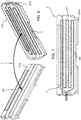
- Figures 4 and 5 show a possible embodiment of a panel 2 according to the principles described above.
- the panel 2 comprises a body 101, and a cover 102 configured to wrap the body 101 and therefore having a shape such as to be form-fit coupled and fixed thereto in a known manner.
- the cover 102 can be made of high-density polyethylene or other plastic material with similar physical characteristics, and the body 101 can be made of expanded polypropylene (EPP).
- the body 101 is configured to define a seat 103 suitable to house the filament 5 made of electrically conductive material.
- the seat 103 is substantially rectangular and formed in the centre of the body 101.
- the cover 102 is coupled to the body 101, the seat 103 is obviously insulated with respect to the external environment.
- the filament 5 is made as a resistive-coated printed circuit board (PCB) 104 comprising a connector 105 configured to keep two input and output portions 104', 104'' of the printed circuit board 104 separated and to connect them to the electronic unit 4 and/or to the above-mentioned functional elements.
- PCB printed circuit board
- the printed circuit board 104 may comprise portions of reduced thickness, or cuts, (not clearly shown) configured to facilitate the breaking of the printed circuit board 104 in the event of an impact.
- FIGS. 6 and 7 show a further embodiment of a panel 2 according to the principles described above.
- the panel 2 comprises a single pair of elements 202 made of high-density polyethylene, for example.
- Each element 201 is configured to define a first face 201a and a second face 201b opposite the first, therefore a face 201a facing outwards and a face 201b facing the inside of the vehicle.
- the two elements 201 are configured to be coupled on top of each other so that the inner face 201b of one element cooperates in contact with the outer face 201a of the other.
- the filament 5 is made by deposition of electrically conductive paint 202 on one of the faces 201a, 201b, in particular on the second, inner face 201b of one of the elements 201.
- the system of the sensorized panel 2 according to the invention allows the insulation of dangerous functional elements of the vehicle 1 to be released from the deployment of the air-bag system 3 of the vehicle.
- the system set out herein is particularly cost-effective and does not substantially increase the overall dimensions either outside or inside the vehicle 1.
- An effective example of this reduction is the use of an electrically conductive paint layer to define the filament 5.
- the filament 5 can be arranged in any way on the panel 2, or inside it, which can define different shapes and be made of different materials.
- the reduced-thickness portion 2a can be of a shape and number different from those described, just like the connection of the filament to the electronic unit 4 and/or to the functional elements of the vehicle 1.
- the shape defined by the body of the panel 2 and its position on the vehicle 1 can be any shape and position.
Landscapes
- Engineering & Computer Science (AREA)
- Automation & Control Theory (AREA)
- Mechanical Engineering (AREA)
- Air Bags (AREA)
Applications Claiming Priority (1)
| Application Number | Priority Date | Filing Date | Title |
|---|---|---|---|
| IT102020000005779A IT202000005779A1 (it) | 2020-03-18 | 2020-03-18 | Pannello sensorizzato per rilevazione di impatto in un veicolo |
Publications (1)
| Publication Number | Publication Date |
|---|---|
| EP3882086A1 true EP3882086A1 (fr) | 2021-09-22 |
Family
ID=70805076
Family Applications (1)
| Application Number | Title | Priority Date | Filing Date |
|---|---|---|---|
| EP21163546.1A Pending EP3882086A1 (fr) | 2020-03-18 | 2021-03-18 | Panneau sensoriel pour la détection d'un impact sur un véhicule |
Country Status (2)
| Country | Link |
|---|---|
| EP (1) | EP3882086A1 (fr) |
| IT (1) | IT202000005779A1 (fr) |
Citations (5)
| Publication number | Priority date | Publication date | Assignee | Title |
|---|---|---|---|---|
| EP1698453A1 (fr) * | 2005-03-04 | 2006-09-06 | Nippon Sheet Glass Company, Limited | Panneau |
| WO2010042848A1 (fr) * | 2008-10-09 | 2010-04-15 | Adc Telecommunications, Inc. | Mécanisme de commutation de puissance |
| WO2010136863A1 (fr) * | 2009-05-26 | 2010-12-02 | Nissan Motor Co., Ltd. | Structure de refroidissement de batterie d'accumulateurs d'un véhicule |
| EP2360061A1 (fr) * | 2008-11-21 | 2011-08-24 | Hitachi, Ltd. | Panneau fonctionnel et procédé pour son assemblage |
| DE102015201440A1 (de) * | 2015-01-28 | 2016-07-28 | Bayerische Motoren Werke Aktiengesellschaft | Versorgungsschiene für ein Kraftfahrzeug |
-
2020
- 2020-03-18 IT IT102020000005779A patent/IT202000005779A1/it unknown
-
2021
- 2021-03-18 EP EP21163546.1A patent/EP3882086A1/fr active Pending
Patent Citations (5)
| Publication number | Priority date | Publication date | Assignee | Title |
|---|---|---|---|---|
| EP1698453A1 (fr) * | 2005-03-04 | 2006-09-06 | Nippon Sheet Glass Company, Limited | Panneau |
| WO2010042848A1 (fr) * | 2008-10-09 | 2010-04-15 | Adc Telecommunications, Inc. | Mécanisme de commutation de puissance |
| EP2360061A1 (fr) * | 2008-11-21 | 2011-08-24 | Hitachi, Ltd. | Panneau fonctionnel et procédé pour son assemblage |
| WO2010136863A1 (fr) * | 2009-05-26 | 2010-12-02 | Nissan Motor Co., Ltd. | Structure de refroidissement de batterie d'accumulateurs d'un véhicule |
| DE102015201440A1 (de) * | 2015-01-28 | 2016-07-28 | Bayerische Motoren Werke Aktiengesellschaft | Versorgungsschiene für ein Kraftfahrzeug |
Also Published As
| Publication number | Publication date |
|---|---|
| IT202000005779A1 (it) | 2021-09-18 |
Similar Documents
| Publication | Publication Date | Title |
|---|---|---|
| EP1645475B1 (fr) | Dispositif d'alimentation pour véhicules | |
| KR102106344B1 (ko) | 복수의 배터리 셀들의 과충전을 방지하기 위한 배터리 보호 모듈 및 배터리 모듈 | |
| US5645746A (en) | Use of PTC devices | |
| US9742166B2 (en) | Wire harness | |
| US7495880B2 (en) | Circuit board and electric device having circuit board | |
| US20150109746A1 (en) | Electronic control device including interrupt wire | |
| JP5841898B2 (ja) | 車載用電子装置およびそれを搭載した車両 | |
| EP2993681B1 (fr) | Sectionneur mécanique avec protection de fusible intégrée | |
| US9490094B2 (en) | Overcurrent protection apparatus | |
| CN108768336B (zh) | 车载电路单元 | |
| US20050087355A1 (en) | Electric connecting box | |
| EP3882086A1 (fr) | Panneau sensoriel pour la détection d'un impact sur un véhicule | |
| JPH08190809A (ja) | ヒューズ付き電線 | |
| US6676156B2 (en) | Electronic impact sensor mounted on supporting member | |
| US10938142B2 (en) | Electrical connection box | |
| CN210652975U (zh) | 一种线束防护支架及防护结构 | |
| US10833466B2 (en) | Rotary connector device | |
| EP1544570B1 (fr) | Détonateur | |
| JP2020124007A (ja) | 電池回路 | |
| KR100223470B1 (ko) | 다방향 충격 감지용 센서 | |
| JP2008506963A (ja) | 容量性送信電極 | |
| WO2017163833A1 (fr) | Structure pour protéger un circuit directement en aval d'une batterie | |
| JP4194928B2 (ja) | 高感度ヒューズ | |
| JPH07143644A (ja) | 電気接続箱 | |
| KR20220157699A (ko) | 파이로 퓨즈 |
Legal Events
| Date | Code | Title | Description |
|---|---|---|---|
| PUAI | Public reference made under article 153(3) epc to a published international application that has entered the european phase |
Free format text: ORIGINAL CODE: 0009012 |
|
| STAA | Information on the status of an ep patent application or granted ep patent |
Free format text: STATUS: THE APPLICATION HAS BEEN PUBLISHED |
|
| AK | Designated contracting states |
Kind code of ref document: A1 Designated state(s): AL AT BE BG CH CY CZ DE DK EE ES FI FR GB GR HR HU IE IS IT LI LT LU LV MC MK MT NL NO PL PT RO RS SE SI SK SM TR |
|
| STAA | Information on the status of an ep patent application or granted ep patent |
Free format text: STATUS: REQUEST FOR EXAMINATION WAS MADE |
|
| 17P | Request for examination filed |
Effective date: 20220316 |
|
| RBV | Designated contracting states (corrected) |
Designated state(s): AL AT BE BG CH CY CZ DE DK EE ES FI FR GB GR HR HU IE IS IT LI LT LU LV MC MK MT NL NO PL PT RO RS SE SI SK SM TR |
|
| STAA | Information on the status of an ep patent application or granted ep patent |
Free format text: STATUS: EXAMINATION IS IN PROGRESS |
|
| 17Q | First examination report despatched |
Effective date: 20230411 |