EP3878060B1 - Hochstromsteckverbinder und steckverbindersystem - Google Patents
Hochstromsteckverbinder und steckverbindersystem Download PDFInfo
- Publication number
- EP3878060B1 EP3878060B1 EP19802056.2A EP19802056A EP3878060B1 EP 3878060 B1 EP3878060 B1 EP 3878060B1 EP 19802056 A EP19802056 A EP 19802056A EP 3878060 B1 EP3878060 B1 EP 3878060B1
- Authority
- EP
- European Patent Office
- Prior art keywords
- plug connector
- contact
- mating
- current
- plug
- Prior art date
- Legal status (The legal status is an assumption and is not a legal conclusion. Google has not performed a legal analysis and makes no representation as to the accuracy of the status listed.)
- Active
Links
Images


Classifications
-
- H—ELECTRICITY
- H01—ELECTRIC ELEMENTS
- H01R—ELECTRICALLY-CONDUCTIVE CONNECTIONS; STRUCTURAL ASSOCIATIONS OF A PLURALITY OF MUTUALLY-INSULATED ELECTRICAL CONNECTING ELEMENTS; COUPLING DEVICES; CURRENT COLLECTORS
- H01R13/00—Details of coupling devices of the kinds covered by groups H01R12/70 or H01R24/00 - H01R33/00
- H01R13/64—Means for preventing incorrect coupling
-
- H—ELECTRICITY
- H01—ELECTRIC ELEMENTS
- H01R—ELECTRICALLY-CONDUCTIVE CONNECTIONS; STRUCTURAL ASSOCIATIONS OF A PLURALITY OF MUTUALLY-INSULATED ELECTRICAL CONNECTING ELEMENTS; COUPLING DEVICES; CURRENT COLLECTORS
- H01R13/00—Details of coupling devices of the kinds covered by groups H01R12/70 or H01R24/00 - H01R33/00
- H01R13/62—Means for facilitating engagement or disengagement of coupling parts or for holding them in engagement
- H01R13/629—Additional means for facilitating engagement or disengagement of coupling parts, e.g. aligning or guiding means, levers, gas pressure electrical locking indicators, manufacturing tolerances
- H01R13/631—Additional means for facilitating engagement or disengagement of coupling parts, e.g. aligning or guiding means, levers, gas pressure electrical locking indicators, manufacturing tolerances for engagement only
- H01R13/6315—Additional means for facilitating engagement or disengagement of coupling parts, e.g. aligning or guiding means, levers, gas pressure electrical locking indicators, manufacturing tolerances for engagement only allowing relative movement between coupling parts, e.g. floating connection
-
- H—ELECTRICITY
- H01—ELECTRIC ELEMENTS
- H01R—ELECTRICALLY-CONDUCTIVE CONNECTIONS; STRUCTURAL ASSOCIATIONS OF A PLURALITY OF MUTUALLY-INSULATED ELECTRICAL CONNECTING ELEMENTS; COUPLING DEVICES; CURRENT COLLECTORS
- H01R13/00—Details of coupling devices of the kinds covered by groups H01R12/70 or H01R24/00 - H01R33/00
- H01R13/62—Means for facilitating engagement or disengagement of coupling parts or for holding them in engagement
- H01R13/627—Snap or like fastening
- H01R13/6278—Snap or like fastening comprising a pin snapping into a recess
-
- H—ELECTRICITY
- H01—ELECTRIC ELEMENTS
- H01R—ELECTRICALLY-CONDUCTIVE CONNECTIONS; STRUCTURAL ASSOCIATIONS OF A PLURALITY OF MUTUALLY-INSULATED ELECTRICAL CONNECTING ELEMENTS; COUPLING DEVICES; CURRENT COLLECTORS
- H01R13/00—Details of coupling devices of the kinds covered by groups H01R12/70 or H01R24/00 - H01R33/00
- H01R13/64—Means for preventing incorrect coupling
- H01R13/645—Means for preventing incorrect coupling by exchangeable elements on case or base
-
- H—ELECTRICITY
- H01—ELECTRIC ELEMENTS
- H01R—ELECTRICALLY-CONDUCTIVE CONNECTIONS; STRUCTURAL ASSOCIATIONS OF A PLURALITY OF MUTUALLY-INSULATED ELECTRICAL CONNECTING ELEMENTS; COUPLING DEVICES; CURRENT COLLECTORS
- H01R13/00—Details of coupling devices of the kinds covered by groups H01R12/70 or H01R24/00 - H01R33/00
- H01R13/02—Contact members
- H01R13/15—Pins, blades or sockets having separate spring member for producing or increasing contact pressure
- H01R13/17—Pins, blades or sockets having separate spring member for producing or increasing contact pressure with spring member on the pin
-
- H—ELECTRICITY
- H01—ELECTRIC ELEMENTS
- H01R—ELECTRICALLY-CONDUCTIVE CONNECTIONS; STRUCTURAL ASSOCIATIONS OF A PLURALITY OF MUTUALLY-INSULATED ELECTRICAL CONNECTING ELEMENTS; COUPLING DEVICES; CURRENT COLLECTORS
- H01R13/00—Details of coupling devices of the kinds covered by groups H01R12/70 or H01R24/00 - H01R33/00
- H01R13/62—Means for facilitating engagement or disengagement of coupling parts or for holding them in engagement
- H01R13/629—Additional means for facilitating engagement or disengagement of coupling parts, e.g. aligning or guiding means, levers, gas pressure electrical locking indicators, manufacturing tolerances
- H01R13/62933—Comprising exclusively pivoting lever
-
- H—ELECTRICITY
- H01—ELECTRIC ELEMENTS
- H01R—ELECTRICALLY-CONDUCTIVE CONNECTIONS; STRUCTURAL ASSOCIATIONS OF A PLURALITY OF MUTUALLY-INSULATED ELECTRICAL CONNECTING ELEMENTS; COUPLING DEVICES; CURRENT COLLECTORS
- H01R2101/00—One pole
Definitions
- the invention is based on a high-current connector according to the preamble of independent claim 1.
- the invention is based on a high-current connector system, having the high-current connector according to claim 1 and a mating connector.
- Such high-current connectors can be used particularly advantageously with said mating connector, which in particular has an angled cable outlet, for example in the form of the aforementioned high-current connector system.
- the high-current connector and the mating connector can be encoded as belonging to one another.
- Such a high-current connector system is required, for example, to connect a correspondingly strong stranded conductor to a battery, e.g. to supply electricity to an electric motor in an electric car.
- the high-current connector usually has an attachment housing, an insulating body and a plug-in contact with which it can be electrically and mechanically connected to a busbar. More than 25 A (amperes), in particular more than 75 A, for example 150 A and more, can be transmitted via the plug contact of the high-current connector.
- a single-pole, angled connector which has a connector housing, an insulating body and a contact.
- the connector is formed at right angles and for Designed to be mounted on an equipment wall or other surface.
- the associated contact element is also formed at right angles and in one piece.
- a two-part insulating body is required for the assembly of the connector, which is mounted in the connector installation housing from two directions.
- the pamphlet proposes DE 10 2011 004 347 A1 a multi-pin electrical connector.
- This electrical connector is used to establish a plug connection with a mating connector.
- the electrical connector includes a housing and a seal disposed on the housing.
- the connector can have an angled cable outlet of 90° in order to reduce the space requirement.
- a high current connector system is also disclosed. This includes such an electrical connector and a mating connector that can be plugged into the electrical connector.
- the high-current connector system can in particular be a high-voltage or HV high-current connector system (“high voltage”) that can be used in hybrid, battery and/or fuel cell vehicles, with the aid of which high-voltage lines can be connected electrically to devices such as batteries, electric motors, etc .can be connected.
- high voltage high-voltage or HV high-current connector system
- the mating connector also has elevations formed on the base part and extending beyond the underside, with the help of which the mating connector can be "coded” in order, for example, to connect the mating connector only to specific devices (with the recesses assigned to the elevations) and/or to be able to screw onto a device in a predetermined orientation.
- the pamphlet WO 2016/131526 A1 discloses an angled high-current connector having an inner conductor contact for carrying current, an outer conductor portion, and an insulator portion that spaced the inner conductor contact from the outer conductor portion. At the connector an elastically compressible damping element is provided. This can be elastically compressed when a complementary mating connector is plugged into the connector, thereby reducing the mobility of the insulator part relative to the inner conductor contact.
- the object of the invention is therefore to specify a high-current connector that can be encoded for use with a specific mating connector and can be flexibly and conveniently adapted to the conditions of the installation space in which it is used.
- a high-current connector is provided for installation and/or attachment in or on an electrical device, namely on a power rail of this device, and for plugging with a mating connector and for transmitting electrical energy to the mating connector.
- the high-current connector has an insulating body.
- the insulator has a polarization element to determine the orientation of the
- the high-current connector has an insulating body.
- the insulator has a polarization element to determine the orientation of the mating connector on the insulator, as well as a coding element to prevent incorrect connections.
- the coding element can bring about a specific coding due to its position relative to the polarization element.
- the high-current connector has a plug-in contact arranged in its insulating body with a plug-in axis, the plug-in contact having a plug-in area at a first end and a connection area with a screw thread, in particular an external thread, opposite this at a second end.
- the plug contact is preferably a pin contact.
- the attachment housing and the plug contact in particular the pin contact, can each be fixed to the electrical device and the plug contact can also be electrically contacted with it.
- the plug contact in particular the pin contact, can be fixed to a busbar of the electrical device and make electrical contact with it.
- the screw thread of the plug contact which is preferably an external thread, can be screwed into an internal thread of a cylindrical passage opening in the busbar.
- the male contact can be guided with its external thread through an unthreaded, cylindrical passage opening of a busbar and screwed to it with one or two screw nuts, e.g. on both sides.
- the insulator is held on the plug-in contact and optionally also in the attachment housing so that it can rotate about the plug-in axis.
- the plug contact can in particular be a pin contact.
- the plug-in area of the pin contact can then be formed by a contact pin.
- the mating connector can A current of 25 A (ampere), in particular more than 75 A, for example more than 100 A or even 150 A and more, can flow electrical energy via the plug contact and the mating plug contact.
- the high-current connector has an attachment housing that can be fixed to the electrical device, the insulating body being arranged in the attachment housing and being held therein so that it can rotate about the plug-in contact axis.
- the invention is of particular advantage because not only is the insulating body on the electrical device held so that it can rotate about the plug-in axis, but also the mating connector plugged in with it and aligned and coded on the insulating body. If the mating connector has an angled cable outlet, then this cable outlet can also be variably rotated in any desired direction in the installed and plugged-in state due to said rotatability of the insulator in a plane perpendicular to the plug-in direction. This is of particular advantage when the high-current connector is installed in or on the electrical device, e.g.
- the cable outlet of the mating connector connected to it can be rotated about the plug contact axis relative to the busbar, i.e. to the electrical device .
- the cable outlet can point in any desired direction, which is in a plane at right angles to the plug contact axis.
- This gives a particularly high degree of flexibility, especially in a particularly cramped or otherwise restrictive installation space.
- the is perpendicular to the connector axis. This gives a particularly high degree of flexibility, especially in a particularly cramped or otherwise restrictive installation space.
- operation is particularly convenient because the mating connector only has to be turned manually in the desired direction.
- a screw and/or a screw nut does not have to be loosened and screwed back in after changing the position of the add-on housing.
- the coding is retained so that mismating is still prevented.
- the coding can take place in particular by defining the relative position between the coding element and the polarization element of the insulating body.
- the insulating body can have a circumferential collar and a cavity enclosed by it.
- the plug-in contact in particular the pin contact, can protrude into this cavity with its plug-in area, in particular with its contact pin.
- the otherwise hollow-cylindrical collar of the insulating body of the high-current connector can, as a polarization element, have a different, polarizing shape on a specific section, namely a polarization section, which defines the orientation of the mating connector that may be plugged into it on the insulating body.
- the polarization section can therefore be flattened, for example, ie in other words the collar in the polarization section can be flat, while it is otherwise designed in the form of a hollow cylinder.
- the insulating body can have a molded coding on its peripheral collar. Due to its position relative to the polarization element, in particular to the polarization section, the molded coding can bring about said coding.
- the molded coding element can be arranged opposite the polarization element on the circumferential collar.
- the mating connector can have a mating coding recess on a mating insulating body as a mating coding element, which corresponds to the molded coding part of the collar during the plugging process and interacts in a coding manner due to its shape and position.
- the counter-insulating body of the counter-connector can also have a counter-polarization element.
- its shape can be complementary to the polarization section of the insulating body and can be inserted with a precise fit in its collar.
- the counter-insulating body can also have a suitable flattened section, namely the said counter-polarization section, which corresponds to the polarization section of the surrounding collar of the insulator and interacts with it in an aligning manner when plugged in.
- the mating connector In the plugged-in state, the mating connector can thereby be fixed in its orientation on the insulator.
- the mating connector can be cylindrical in its mating mating area.
- the coding recess of the mating connector can be arranged opposite its mating polarization section on the mating insulating body.
- the counter-insulating body can thus be insertable at least partially, namely with a plug-in section, in particular in a form-fitting manner, into the peripheral collar of the insulating body during the plugging process.
- the plugging process can take place. Otherwise the high-current connector and the mating connector do not match and the mating process is automatically prevented.
- the plug contact in particular the pin contact, can preferably be made of metal. In particular, it can be a turned part.
- the plug contact in particular the pin contact, can have a recess, in particular a circumferential groove, in its plug-in area, in particular its contact pin, in which a contact spring, in particular a circumferential spiral spring, is arranged for electrical contacting of the mating plug contact, in particular the socket contact, of the mating connector .
- the plug contact in particular the pin contact, can have a protection against accidental contact at the free-standing end of its plug-in area, in particular its contact pin, which consists of an electrically insulating material, in particular plastic.
- the connector housing can have a mounting flange for its attachment. With this, it can be attached to a housing of the electrical device, for example.
- the high-current connector can advantageously be single-pole, i.e. have exactly one plug contact.
- the screw thread of the plug contact on the connection side can be an external thread.
- the plug contact of the high-current plug connector can be screwed in or screwed into or on the busbar of the electrical device and thus be mechanically fixed thereto and at the same time electrically contactable therewith.
- the exact alignment of the plug contact can often not be precisely determined.
- the orientation of the plug contact and the attachment housing relative to the busbar is then fixed arbitrarily.
- the angled cable outlet of the mating connector plugged in therewith can still be aligned in the desired direction independently of this, since the mating connector is finally aligned on the rotatably held insulating body of the high-current connector.
- the high-current connector system has the high-current connector and the mating connector, the mating connector having said angled cable outlet.
- the high-current connector and the mating connector can have a common coding that defines them as belonging to one another and as being able to be plugged into one another. Conversely, there can also be other mating connectors, one have a different coding and therefore cannot be plugged into the high-current connector. This has the advantage that incorrect insertions, ie plug connections defined as undesirable, can be avoided.
- the mating connector can also be fixed with regard to its pluggability and the alignment of its angled cable outlet by the relative position of its counter-coding element to its counter-polarization element on the insulating body of the high-current connector. Due to the rotatability of the insulating body relative to the add-on housing, the cable outlet of the mating connector aligned on the insulating body can be rotated around the plug contact axis, i.e. held variably on the high-current connector.
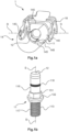
- the Fig.1a shows a high-current connector 1 with an insulating body 14.
- the insulating body 1 has a circumferential collar 148 through which a cavity 140 is formed.
- a plug contact in the form of a pin contact 11 is rotatably held about its pin axis S in the insulating body 14 .
- the insulator 14 is held on the plug contact 11 so that it can rotate about the pin axis S.
- the plug contact 11 is a high-current contact and can, for example, transmit currents of 10 A (amperes) and more.
- the plug contact could also be a socket contact, a hermaphrodite contact or any other plug contact which is able
- the plug contact could also be a socket contact, a hermaphrodite contact or any other plug contact which is able to transmit currents of, for example, 10 A and more.
- the high-current connector 1 has a locking clip 18 which is held on the peripheral collar 148 of the insulating body 14 and can be pivoted about an axis of rotation D, with the axis of rotation D running perpendicular to the axis S of the pin.
- a mating connector 4 plugged into the high-current connector 1 can be locked on the high-current connector 1 by this pivoting movement.
- the locking bracket 18 is held rotatably about the axis of rotation D on two opposite pivot pins 143 .
- the peripheral collar 148 has a polarization element in the form of a flat polarization section 146, which is provided for aligning the mating connector 4 plugged therewith.
- the circumferential collar 148 has a flat shape.
- the insulating body 14 has on its peripheral collar 148 a coding element in the form of a coding projection 145 which is directed inwards, i.e. protrudes into the cavity 140.
- the pin contact 11 is in the Fig.1b shown separately again.
- the pin axis S drawn in this illustration is formed by the axis of symmetry of the pin contact 11 .
- the pin contact 11 has in its plug-in area, which is designed as a contact pin 116, an unspecified circumferential groove in which a contact spring in the form of a ring-shaped spiral spring 118 for electrically contacting a contact socket 411 of the mating connector 4 is arranged.
- the pin contact 11 has a connection area 117 with a screw thread designed as an external thread 113 for screwing in or on a busbar, not shown in the drawing, of an electrical device or the like.
- the plug contact 11 has a plate-shaped separating collar 132 and a nut section 131.
- the latter is used, for example, for manually screwing the external thread 113 into an internal thread of the busbar using a wrench or for holding ("countering") ) of the pin contact 11 in a comparable screwing or assembly process.
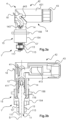
- the 2 shows another high-current connector 1 ', which largely corresponds to the aforementioned high-current connector 1, but is additionally equipped with an attachment housing 15.
- the Figure 2a shows this high-current connector 1 'in an oblique plan view.
- the Figure 2b shows it in a cross-sectional view.
- the attachment housing 15 has a hollow-cylindrical sleeve 154 into which the insulating body 145 is inserted.
- the insulating body 14 is held in the attachment housing 15 so that it can rotate about the pin axis S.
- the attachment housing 15 also has a mounting flange 156 with screw passages 150 for mounting, for example, to a device housing of the electrical device, not shown in the drawing Contraption.
- two screw nuts 13, 13′ are arranged on the external thread 113 of the connection area 117 of the pin contact 11, with which the pin contact 11 can be screwed, for example, to the busbar of the said electrical device and thereby attached to it and electrically contacted with it.
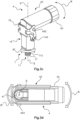
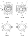
- FIGS. 3a and 3b show a high-current connector system, comprising the above-mentioned high-current connector 1' and a mating connector 4.
- the mating connector 4 is inserted with its mating mating region 441 of its mating insulating body 44, which is not visible in this representation, into the high-current connector 1' and locked with its locking pin 443 on its locking bracket 18.
- the mating connector 4 is an angled connector, i.e. it has a cable outlet 42 which is angled from its mating connector area 441.
- the cable outlet 42 is angled by 90° from the mating plug area 441, but other angular positions are also possible.
- the use of angled connectors basically has the advantage of saving space in the plug-in direction.
- the cable outlet 42 is made up of a separate retaining plate 421 and a part of the counter-insulating body 44 on the cable connection side that is angled away from the mating connector area 441.
- the insulating body 14 of the high-current connector 1 is rotatably mounted and can thus despite the attachment of the pin contact 11 and possibly the Attachment housing 15 are rotated about the plug contact axis S. Since the locking bracket 18 - not as usual on the attachment housing 15 - but on the rotatable insulating body 14 is held, the mating connector 4 with its angled cable outlet 42 can also be rotated around the plug contact axis S without any problems.
- the locking bracket 18 can be held pivotably on the mating connector 4 and can latch on the insulating body 14 of the high-current connector 1'.
- the decisive factor here is that the mating connector 4 is fixed to the insulating body 14 and not to the attachment housing 15 by the locking mechanism.
- the mating plug contact 4 has a mating plug contact in the form of a socket contact 41. This is also angled. Its plug-in area is designed as a contact socket 411 and is, as in the Figure 3b can be seen well, with the contact pin 116 of the pin contact 11 plugged.
- the mating connector 4 has a cable gland 43 on its cable outlet 42 for strain relief and sealing of a cable connected to it. This is only mentioned for the sake of completeness.
- FIGS. 3c and 3d illustrate a similar device from other perspectives for the first-mentioned high-current connector 1, which has no attachment housing 14.
- the insulating body 14 is held on the pin contact 11 only so that it can rotate.
- the pin contact 11 can be screwed to the external thread 113 of its connection area 117, for example on a busbar of the electrical device and thereby mechanically fixed thereto and electrically connected thereto.
- the insulating body 14 is held on the pin contact 11 so that it can rotate about the plug-in axis S.
- the curved double-headed arrows R, R' symbolize the respective rotational movement, i.e. rotary movement, about the plug-in contact axis S.
- the first curved double-headed arrow R shows the rotary movement that the cable outlet 42 of the mating connector can perform.
- the second curved double arrow R' symbolizes the associated rotational movement of the insulating body 14 about the plug-in contact axis S.
- the 3c shows the complete high-current connector system in the plugged and locked state in an oblique top view.
- the 3d shows the high-current connector system without the retaining plate 42 in a vertical plan view. Due to the absence of the retaining plate 42, the cable connection area 413 of the socket contact 41 can be seen
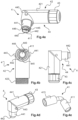
- the Fig. 4a - d show the angled mating connector 4 in different views, namely an oblique side view, a front view, a side view and an oblique top view.
- the mating connector 4 has a retaining plate 421 and a counter insulating body 44.
- counter-insulating body 44 has a counter-plug area 441 with a counter-polarization element in the form of a flat counter-polarization section 446. Opposite this counter-polarization section 446, counter-plug area 441 has a coding recess 445 as a counter-coding element.
- This has a plug contact opening 440, which in the Figure 4a the look at that The Figure 4e shows the angled socket contact 41, the cable connection area 413 is designed as a crimp connection.
- the cable connection area 413 and said contact socket 411 are arranged at right angles to one another.
- You Fig. 4f shows said holding plate 421 in a side view.
- the Figures 4g and 4h show the counter-insulating body 44 in an oblique plan view.
- the Figures 5a - 5d show different codings of the insulating body 14 of the high-current connector 1, 1 '.
- the Figure 5a shows another high-current connector 1 'with the attachment housing 15 and its mounting flange 156.
- the contact pin 116 of the pin contact 11 is covered by the contact protection 12 plugged thereon.
- the nut portion and the disk-shaped separating collar are clearly visible in this illustration.
- the pin contact 11 is attached with its thread 113 and the attachment housing 15 with its mounting flange 156 on the electrical device, not shown. The pin contact 11 and the attachment housing are therefore in a fixed position relative to one another.
- the insulating body 14, of which only the peripheral collar 148 can be seen in this illustration, has the polarization section 146 (shown at the top in the drawing) on this peripheral collar 148 and opposite the inwardly directed coding projection 145.
- the respective coding projections 145', 145" are each located on a different area of the circumferential collar 148, which then results in a different coding.
- an angular distance of 90° is also possible, as is exemplified in FIG Figures 5c and 5d is shown.
- the respective coding formation 145′, 145′′ lies on the axis of rotation D.
- a large number of other angular distances for different coding are also possible, so that a very large number of different codings are possible.
- this is implemented as follows: In the case of the high-current connector, this relative position is formed between the coding projection 145 and the polarization section 146, in the case of the mating connector between the polarization cutout 445 and the counter-polarization section 446.
- the high-current connector 1, 1' can be plugged into the mating connector 4.
- the mating connector 4 can be flexibly aligned with its angled cable outlet 42 .
Landscapes
- Connector Housings Or Holding Contact Members (AREA)
- Details Of Connecting Devices For Male And Female Coupling (AREA)
Description
- Die Erfindung geht aus von einem Hochstromsteckverbinder nach dem Oberbegriff des unabhängigen Anspruchs 1.
- Weiterhin geht die Erfindung aus von einem Hochstromsteckverbindersystem, aufweisend den Hochstromsteckverbinder gemäß Anspruch 1 und einen Gegensteckverbinder.
- Derartige Hochstromsteckverbinder können besonders vorteilhaft mit dem besagten Gegensteckverbinder, der insbesondere einen gewinkelten Kabelabgang aufweist, beispielsweise in Form des vorgenannten Hochstromsteckverbindersystems verwendet werden. Um Fehlsteckungen zu vermeiden, können der Hochstromsteckverbinder und der Gegensteckverbinder als einander zugehörig kodiert sein. Ein solches Hochstromsteckverbindersystem wird beispielsweise benötigt, um einen entsprechend starken Litzenleiter an eine Batterie anzuschließen, z.B. um einen Elektromotor in einem Elektroauto mit elektrischem Strom zu versorgen. Üblicherweise besitzt der Hochstromsteckverbinder ein Anbaugehäuse, einen Isolierkörper und einen Steckkontakt, mit dem er elektrisch und mechanisch mit einer Stromschiene verbindbar ist. Über den Steckkontakt des Hochstromsteckverbinders können mehr als 25 A (Ampere), insbesondere mehr als 75 A, beispielsweise 150 A und mehr übertragen werden.
- Im Stand der Technik ist aus der Druckschrift
DE 10 2015 113 786 A1 ein einpoliger, gewinkelter Steckverbinder bekannt, welcher ein Steckverbindergehäuse, einen Isolierkörper und einen Kontakt aufweist. Dabei ist der Steckverbinder rechtwinkelig ausgebildet und für die Montage auf einer Gerätewand oder einer anderen Oberfläche ausgebildet. Das dazugehörige Kontaktelement ist ebenfalls rechtwinkelig und einstückig ausgebildet. Für die Montage des Steckverbinders ist ein zweiteiliger Isolierkörper notwendig, welcher aus zwei Richtungen in dem Steckverbindereinbaugehäuse montiert wird. - Darauf aufbauend schlägt die Druckschrift
DE 10 2011 004 347 A1 einen mehrpoligen elektrischen Verbinder vor. Dieser elektrische Verbinder dient zum Herstellen einer Steckverbindung mit einem Gegenverbinder. Der elektrische Verbinder weist ein Gehäuse sowie eine an dem Gehäuse angeordnete Dichtung auf. Der Verbinder kann einen abgewinkelten Leitungsabgang von 90° besitzen um den Platzbedarf zu reduzieren. Weiterhin wird ein Hochstromsteckverbindersystem offenbart. Dies umfasst einen solchen elektrischen Verbinder und einen mit dem elektrischen Verbinder steckbaren Gegenverbinder. Bei dem Hochstromsteckverbindersystem kann es sich insbesondere um ein bei Hybrid-, Batterie- und/oder Brennstoffzellenfahrzeugen einsetzbares Hochspannungs- bzw. HV-Hochstromsteckverbindersystem ("High Voltage") handeln, mit dessen Hilfe Hochspannungsleitungen elektrisch an Vorrichtungen wie zum Beispiel Batterien, Elektromotoren, usw. angeschlossen werden können. Auch weist der Gegenverbinder an dem Basisteil ausgebildete und sich über die Unterseite hinaus ersteckende Erhebungen auf, mit deren Hilfe eine "Kodierung" des Gegenverbinders verwirklicht werden kann, um zum Beispiel den Gegenverbinder nur auf bestimmte Vorrichtungen (mit den Erhebungen zugeordneten Aussparungen) und/oder in einer vorbestimmten Ausrichtung auf eine Vorrichtung aufschrauben zu können. - Die Druckschrift
WO 2016/131526 A1 offenbart einen gewinkelten Hochstrom-Steckverbinder mit einem Innenleiterkontakt zur Stromführung, einem Außenleiterteil und einem den Innenleiterkontakt von dem Außenleiterteil beabstandet haltenden Isolatorteil. An dem Steckverbinder ist ein elastisch komprimierbares Dämpfungselement vorgesehen. Dieses ist beim Einstecken eines komplementären Gegensteckverbinders in den Steckverbinder elastisch komprimierbar und verringert dabei die Beweglichkeit des Isolatorteils gegenüber dem Innenleiterkontakt. - Im Hochstrombereich ist es besonders wichtig, Steckverbinder als einander zugehörig kodieren zu können, um so gefährliche Fehlsteckungen auszuschließen. Nachteilig ist dabei, dass durch die üblichen Kodierungen die Richtung eines ggf. gewinkelten Kabelabgangs des gesteckten Gegensteckverbinders automatisch festgelegt ist. Dies sorgt beim Einbau in und/oder an vorgegebene Geräte, z.B. in Motorenräume, Maschinen und/oder Anlagen, etc. aufgrund der dort vorgegebenen und meist beengten Platzverhältnisse zunehmend für Probleme und/oder unerwünschten Aufwand.
- Die Aufgabe der Erfindung besteht folglich darin, einen Hochstromsteckverbinder anzugeben, der zur Verwendung mit einem bestimmten Gegensteckverbinder kodierbar und dabei flexibel und komfortabel an die Gegebenheiten des Bauraums, in dem er eingesetzt wird, anpassbar ist.
- Diese Aufgabe wird durch die Merkmale der unabhängigen Ansprüche gelöst. Vorteilhafte Ausgestaltungen der Erfindung sind in den Unteransprüchen angegeben.
- Ein Hochstromsteckverbinder ist zum Ein- und/oder Anbau in oder an eine elektrische Vorrichtung, nämlich an eine Stromschiene dieser Vorrichtung, sowie zum Stecken mit einem Gegensteckverbinder und zur Übertragung elektrischer Energie an den Gegensteckverbinder vorgesehen.
- Der Hochstromsteckverbinder besitzt einen Isolierkörper. Der Isolierkörper besitzt ein Polarisationselement zur Festlegung der Ausrichtung des Der Hochstromsteckverbinder besitzt einen Isolierkörper. Der Isolierkörper besitzt ein Polarisationselement zur Festlegung der Ausrichtung des Gegensteckverbinders am Isolierkörper, sowie ein Kodierelement zur Vermeidung von Fehlsteckungen. Insbesondere kann das Kodierelement durch seine Relativposition zum Polarisationselement eine bestimmte Kodierung bewirken.
- Der Hochstromsteckverbinder besitzt einen in seinem Isolierkörper angeordneten Steckkontakt mit einer Steckachse, wobei der Steckkontakt an einem ersten Ende einen Steckbereich und diesem gegenüberliegend an einem zweiten Ende einen Anschlussbereich mit einem Schraubgewinde, insbesondere einem Außengewinde, besitzt. Bevorzugt handelt es sich bei dem Steckkontakt um einen Stiftkontakt.
- Das Anbaugehäuse und der Steckkontakt, insbesondere der Stiftkontakt, sind jeweils an der elektrischen Vorrichtung fixierbar und der Steckkontakt ist zusätzlich elektrisch damit kontaktierbar. Insbesondere kann der Steckkontakt, insbesondere der Stiftkontakt, an einer Stromschiene der elektrischen Vorrichtung fixiert werden und elektrisch damit kontaktieren. Beispielsweise kann der Steckkontakt mit seinem Schraubgewinde, bei dem es sich bevorzugt um ein Außengewinde handelt, in ein Innengewinde einer zylindrischen Durchgangsöffnung der Stromschiene eingeschraubt werden. Alternativ oder ergänzend kann der Steckkontakt mit seinem Außengewinde durch eine gewindefreie, zylindrische Durchgangsöffnung einer Stromschiene geführt und mit einer oder zwei Schraubmuttern, z.B. beidseitig, daran festgeschraubt werden. Gleichzeitig ist der Isolierkörper jedoch um die Steckachse drehbar am Steckkontakt und gegebenenfalls auch im Anbaugehäuse gehalten.
- Wie bereits erwähnt, kann es sich bei dem Steckkontakt insbesondere um einen Stiftkontakt handeln. Der Steckbereich des Stiftkontakts kann dann durch einen Kontaktstift gebildet sein. Der Gegensteckverbinder kann elektrischen Energie kann über den Steckkontakt und den Gegensteckkontakt ein Strom von 25 A (Ampere), insbesondere mehr als 75 A, beispielsweise mehr als 100 A oder sogar 150 A und mehr fließen.
- In einer besonders bevorzugten Ausgestaltung weist der Hochstromsteckverbinder ein Anbaugehäuse auf, das an der elektrischen Vorrichtung fixierbar ist, wobei der Isolierkörper in dem Anbaugehäuse angeordnet und um die Steckkontaktachse drehbar darin gehalten ist.
- Die Erfindung ist von besonderem Vorteil, weil somit nicht nur der Isolierkörper an der elektrischen Vorrichtung um die Steckachse drehbar gehalten ist, sondern damit auch der damit gesteckte und an dem Isolierkörper ausgerichtete und kodierte Gegensteckverbinder. Besitzt der Gegensteckverbinder einen gewinkelten Kabelabgang, dann kann dieser Kabelabgang auch im eingebauten und gesteckten Zustand aufgrund der besagten Drehbarkeit des Isolierkörpers in einer Ebene senkrecht zur Steckrichtung variabel in jede gewünschte Richtung gedreht werden. Dies ist von besonderem Vorteil, wenn der Hochstromsteckverbinder in oder an die elektrische Vorrichtung, z.B. eine Maschine oder ein Gerät oder einen Motorenraum oder in irgendeinen anderen Bauraum, eingebaut ist, in dem die Platzverhältnisse eine flexible Ausrichtung verlangen.
- Ist beispielsweise der Steckkontakt anschlussseitig mit seinem Schraubgewinde in oder an der besagten Stromschiene des elektrischen Geräts zur Befestigung und zur elektrischen Verbindung ein- oder angeschraubt, so kann der Kabelabgang des damit verbundenen Gegensteckverbinders relativ zur Stromschiene, also zum elektrischen Gerät, um die Steckkontaktachse gedreht werden. Somit kann der Kabelabgang in jede gewünschte Richtung weisen, welche in einer Ebene rechtwinklig zur Steckkontaktachse liegt. Dadurch ist gerade in einem besonders beengten oder anderweitig restriktiven Bauraum eine besonders hohe Flexibilität gegeben. Insbesondere gestaltet sich die rechtwinklig zur Steckkontaktachse liegt. Dadurch ist gerade in einem besonders beengten oder anderweitig restriktiven Bauraum eine besonders hohe Flexibilität gegeben. Insbesondere gestaltet sich die Bedienung besonders komfortabel, weil der Gegensteckverbinder dazu lediglich händisch in die gewünschte Richtung gedreht werden muss. Es muss dazu also beispielsweise nicht eine Schraube und/oder eine Schraubmutter gelöst und nach Änderung der Position des Anbaugehäuses wieder verschraubt werden. Gleichzeitig bleibt die Kodierung erhalten, so dass Fehlsteckungen weiterhin unterbunden werden.
- Die Kodierung kann insbesondere durch die Festlegung der Relativposition zwischen dem Kodierelement und dem Polarisationselement des Isolierkörpers stattfinden.
- In einer bevorzugten Ausgestaltung kann der Isolierkörper einen umlaufenden Kragen und einen davon eingeschlossenen Hohlraum aufweisen. In diesen Hohlraum kann der Steckkontakt, insbesondere der Stiftkontakt, mit seinem Steckbereich, insbesondere mit seinem Kontaktstift, hineinragen.
- Der ansonsten hohlzylinderförmig ausgebildete Kragen des Isolierkörpers des Hochstromsteckverbinders kann als Polarisationselement an einem bestimmten Abschnitt, nämlich einem Polarisationsabschnitt, eine davon abweichende, polarisierende Form aufweisen, durch welche die Ausrichtung des gegebenenfalls damit gesteckten Gegensteckverbinders am Isolierkörper festgelegt ist. Der Polarisationsabschnitt kann also beispielsweise abgeflacht verlaufen, d.h. mit anderen Worten kann der Kragen im Polarisationsabschnitt flächig ausgeführt sein, währen er sonst hohlzylinderförmig ausgestaltet ist.
- Als Kodierelement kann der Isolierkörper an seinem umlaufenden Kragen eine Kodieranformung besitzen. Die Kodieranformung kann durch ihre Relativposition zum Polarisationselement, insbesondere zum Polarisationsabschnitt, die besagte Kodierung bewirken. Beispielsweise kann die Kodieranformung dem Polarisationselement gegenüberliegend am umlaufenden Kragen angeordnet sein.
- Der Gegensteckverbinder kann an einem Gegenisolierkörper als Gegenkodierelement eine dazu passende Kodierausnehmung aufweisen, die durch ihre Form und ihre Position mit der Kodieranformung des Kragens beim Steckvorgang korrespondiert und kodierend zusammenwirkt.
- Der Gegenisolierkörper des Gegensteckverbinders kann weiterhin ein Gegenpolarisationselement aufweisen. Insbesondere kann er zumindest Abschnittsweise, nämlich mit einem Gegenpolarisationsabschnitt, in seiner Form zum Polarisationsabschnitt des Isolierkörpers komplementär und passgenau in dessen Kragen einfügbar sein.
- Der Gegenisolierkörper kann also, mit anderen Worten gesagt, ebenfalls einen passenden abgeflachten Abschnitt, nämlich den besagten Gegenpolarisationsabschnitt, besitzen, der dem Polarisationsabschnitt des umlaufenden Kragens des Isolierkörpers entspricht und beim Stecken ausrichtend mit diesem zusammenwirkt. Im gesteckten Zustand kann der Gegensteckverbinder dadurch in seiner Ausrichtung am Isolierkörper festgelegt sein.
- Abgesehen von diesem Gegenpolarisationsabschnitt kann der Gegensteckverbinder an seinem Gegensteckbereich zylindrisch ausgeführt sein.
- Beispielsweise kann die Kodierausnehmung des Gegensteckverbinders seinem Gegenpolarisationsabschnitt gegenüberliegend am Gegenisolierkörper angeordnet sein.
- Der Gegenisolierkörper kann somit im Steckvorgang zumindest teilweise, nämlich mit einem Steckabschnitt, insbesondere formschlüssig, in den umlaufenden Kragen des Isolierkörpers einfügbar sein.
- Befinden sich die Kodierausnehmung des Gegensteckverbinders und die Kodieranformung des Hochstromsteckverbinders relativ zum jeweiligen Polarisationsabschnitt bzw. zum Gegenpolarisationsabschnitt in der gleichen Position, so kann der Steckvorgang stattfinden. Anderenfalls passen der Hochstromsteckverbinder und der Gegensteckverbinder nicht zusammen und der Steckvorgang ist automatisch verhindert.
- Bevorzugt kann der Steckkontakt, insbesondere der Stiftkontakt, aus Metall sein. Insbesondere kann es sich um ein Drehteil handeln.
- Der Steckkontakt, insbesondere der Stiftkontakt, kann an seinem Steckbereich, insbesondere seinem Kontaktstift, eine Ausnehmung, insbesondere eine umlaufende Nut besitzen, in welcher eine Kontaktfeder, insbesondere eine umlaufende Spiralfeder, zur elektrischen Kontaktierung des Gegensteckkontakts, insbesondere des Buchsenkontakts, des Gegensteckverbinders, angeordnet ist.
- Aus Gründen der elektrischen Sicherheit kann der Steckkontakt, insbesondere der Stiftkontakt, am freistehenden Ende seines Steckbereichs, insbesondere seines Kontaktstifts, einen Berührschutz aufweisen, der aus einem elektrisch isolierenden Material, insbesondere Kunststoff, besteht.
- Das Steckverbindergehäuse kann zu seiner Befestigung einen Anbauflansch aufweisen. Mit diesem kann es beispielsweise an einem Gehäuse des elektrischen Gerätes befestigt werden.
- Der Hochstromsteckverbinder kann vorteilhafterweise einpolig ausgeführt sein, d.h. genau einen Steckkontakt besitzen.
- Wie bereits erwähnt, kann es sich bei dem anschlussseitige Schraubgewinde des Steckkontakts um ein Außengewinde handeln. Mit diesem Außengewinde kann der Steckkontakt des Hochstromsteckverbinders in oder an der Stromschiene der elektrischen Vorrichtung ein- oder anschraubbar und dadurch mechanisch daran fixierbar und gleichzeitig elektrisch damit kontaktierbar sein.
- Beim Einschraubvorgang des Steckkontakts mit dem Außengewinde in ein Innengewinde der Stromschiene kann die exakte Ausrichtung des Steckkontakts oft nicht genau festgelegt werden. Die Ausrichtung des Steckkontakts und des Anbaugehäuses relativ zur Stromschiene ist dann willkürlich festgelegt. Vorteilhafterweise kann nun aber der gewinkelte Kabelabgang des damit gesteckten Gegensteckverbinders trotzdem davon unabhängig in die gewünschte Richtung ausgerichtet werden, da der Gegensteckverbinder schließlich an dem drehbar gehaltenen Isolierkörper des Hochstromsteckverbinders ausgerichtet ist.
- Das Hochstromsteckverbindersystem weist den Hochstromsteckverbinder und den Gegensteckverbinder auf, wobei der Gegensteckverbinder den besagten gewinkelten Kabelabgang besitzt.
- Wie bereits erwähnt können der Hochstromsteckverbinder und der Gegensteckverbinder eine gemeinsame Kodierung besitzen, durch die sie als einander zugehörig und miteinander steckbar festgelegt sind. Umgekehrt können auch weitere Gegensteckverbinder existieren, die eine andere Kodierung besitzen und daher nicht mit dem Hochstromsteckverbinder steckbar sind. Dies hat den Vorteil, dass Fehlsteckungen, also als ungewünscht festgelegte Steckverbindungen, vermieden werden können.
- Dazu kann auch der Gegensteckverbinder bezüglich seiner Steckbarkeit und der Ausrichtung seines gewinkelten Kabelabgangs durch die Relativposition seines Gegenkodierelements zu seinem Gegenpolarisationselement am Isolierkörper des Hochstromsteckverbinders festgelegt sein. Durch die Drehbarkeit des Isolierkörpers relativ zum Anbaugehäuse ist der Kabelabgang des am Isolierkörper ausgerichteten Gegensteckverbinders um die Steckkontaktachse drehbar, d.h. variabel, am Hochstromsteckverbinder gehalten.
- Ein Ausführungsbeispiel der Erfindung ist in den Zeichnungen dargestellt und wird im Folgenden näher erläutert. Es zeigen:
- Fig. 1 a
- einen Hochstromsteckverbinder ohne Anbaugehäuse, mit einem Isolierkörper mit umlaufendem Kragen, eingefügtem Stiftkontakt und Verriegelungsbügel;
- Fig. 1b
- den Stiftkontakt als separates Bauteil;
- Fig. 2a, b
- einen weiteren Hochstromsteckverbinder mit einem Anbaugehäuse in schräger Draufsicht sowie in einer Querschnittsdarstellung;
- Fig. 3a, b
- ein gestecktes Hochstromsteckverbindersystem, aufweisend den Hochstromsteckverbinder und einen Gegensteckverbinder in Seitenansicht und als Querschnittsdarstellung;
- Fig. 3d
- die vorgenannte Anordnung ohne Halteplatte in der Draufsicht;
- Fig. 4a - d
- den gewinkelten Gegensteckverbinder in verschiedenen Ansichten;
- Fig. 4e
- den gewinkelten Buchsenkontakt des Gegensteckverbinders;
- Fig. 4f
- eine Halteplatte des Gegensteckverbinders in Seitenansicht;
- Fig. 4g - h
- einen Gegenisolierkörper des Gegensteckverbinders aus Seitenansicht und in einer schrägen Draufsicht;
- Fig. 5a - d
- den Hochstromsteckverbinder mit und ohne Anbaugehäuse mit drei verschiedenen Kodierungen.
- Die Figuren enthalten teilweise vereinfachte, schematische Darstellungen. Zum Teil werden für gleiche, aber gegebenenfalls nicht identische Elemente identische Bezugszeichen verwendet. Verschiedene Ansichten gleicher Elemente könnten unterschiedlich skaliert sein.
- Die
Fig.1a zeigt einen Hochstromsteckverbinder 1 mit einem Isolierkörper 14. Der Isolierkörper 1 besitzt einen umlaufendem Kragen 148, durch den ein Hohlraum 140 gebildet ist. Weiterhin ist in den Isolierkörper 14 ein Steckkontakt in Form eines Stiftkontakts 11 um seine Stiftachse S drehbar gehalten. Umgekehrt betrachtet ist somit der Isolierkörper 14 am Steckkontakt 11 um die Stiftachse S drehbar gehalten. Der Steckkontakt 11 ist ein Hochstromkontakt und kann beispielsweise Stromstärken von 10 A (Ampere) und mehr übertragen. - In einer jeweils anderen Ausführung könnte es sich bei dem Steckkontakt aber auch um einen Buchsenkontakt, einen hermaphroditischen Kontakt oder irgendeinen anderen Steckkontakt handeln, welcher in der Lage ist, In einer jeweils anderen Ausführung könnte es sich bei dem Steckkontakt aber auch um einen Buchsenkontakt, einen hermaphroditischen Kontakt oder irgendeinen anderen Steckkontakt handeln, welcher in der Lage ist, Stromstärken von z.B. 10 A und mehr zu übertragen.
- Weiterhin besitzt der Hochstromsteckverbinder 1 einen am umlaufenden Kragen 148 des Isolierkörpers 14 um eine Drehachse D schwenkbar gehaltenen Verriegelungsbügel 18, wobei die Drehachse D senkrecht zur Stiftachse S verläuft. Durch diese Schwenkbewegung ist ein mit dem Hochstromsteckverbinder 1 gesteckter Gegensteckverbinder 4 am Hochstromsteckverbinder 1 verriegelbar. In vorliegenden Beispiel ist der Verriegelungsbügel 18 an zwei einander gegenüberliegenden Drehzapfen 143 um die Drehachse D drehbar gehalten.
- Der umlaufende Kragen 148 besitzt ein Polarisationselement in Form eines flächigen Polarisationsabschnitts 146, der zur Ausrichtung des damit gesteckten Gegensteckverbinders 4 vorgesehen ist. In Bereich dieses Polarisationsabschnitts 146 besitzt der umlaufende Kragen 148 eine flächige Form. Gegenüberliegend, also in einem Winkelabstand von 180°, besitzt der Isolierkörper 14 an seinem umlaufenden Kragen 148 ein Kodierelement in Form einer nach innen gerichteten, d.h. in den Hohlraum 140 hineinragenden, Kodieranformung 145.
- Der Stiftkontakt 11 ist in der
Fig.1b noch einmal gesondert dargestellt. Die in dieser Darstellung eingezeichnete Stiftachse S ist in diesem Fall durch die Symmetrieachse des Stiftkontakts 11 gebildet. - Der Stiftkontakt 11 besitzt an seinem Steckbereich, der als Kontaktstift 116 ausgeführt ist, eine nicht näher bezeichnete umlaufende Nut, in der eine Kontaktfeder in Form einer ringförmig ausgeführten Spiralfeder 118 zur elektrischen Kontaktierung einer Kontaktbuchse 411 des Gegensteckverbinders 4 angeordnet ist.
- An dem frei stehenden Ende seines als Kontaktstift 116 ausgeführten Steckbereichs ist am Stiftkontakt 11 aus Gründen der elektrischen Sicherheit ein Berührschutz 12 aus Kunststoff befestigt.
- Am gegenüberliegenden Ende besitzt der Stiftkontakt 11 einen Anschlussbereich 117 mit einem als Außengewinde 113 ausgeführten Schraubgewinde zur Verschraubung in oder an einer nicht in der Zeichnung dargestellten Stromschiene einer elektrischen Vorrichtung oder dergleichen.
- Zwischen dem Steckbereich/ Kontaktstift 116 und dem Anschlussbereich mit dem Außengewinde 113 besitzt der Steckkontakt 11 einen tellerförmigen Trennkragen 132 sowie einen Schraubmutterabschnitt 131. Letzterer dient z.B. dem händischen Einschrauben des Außengewindes 113 in ein Innengewinde der Stromschiene mittels eines Schraubschlüssels oder zum Festhalten ("Kontern") des Stiftkontakts 11 bei einem vergleichbaren Schraub- oder Montagevorgang.
- Die
Fig. 2 zeigt einen weiteren Hochstromsteckverbinder 1', der dem vorgenannten Hochstromsteckverbinder 1 weitgehend entspricht, jedoch zusätzlich mit einem Anbaugehäuse 15 ausgestattet ist. DieFig. 2a zeigt diesen Hochstromsteckverbinder 1' in schräger Draufsicht. DieFig. 2b zeigt ihn in einer Querschnittsdarstellung. - Das Anbaugehäuse 15 besitzt eine hohlzylinderförmige Hülse 154, in welche der Isolierkörper 145 eingesteckt ist. Dabei ist der Isolierkörper 14 um die Stiftachse S drehbar in dem Anbaugehäuse 15 gehalten.
- Das Anbaugehäuse 15 besitzt weiterhin einen Befestigungsflansch 156 mit Schraubdurchlässen 150 zur Befestigung, z.B. an einem Vorrichtungsgehäuse der nicht in der Zeichnung dargestellten elektrischen Vorrichtung.
- Weiterhin sind am Außengewinde 113 des Anschlussbereichs 117 des Stiftkontakts 11 zwei Schraubmuttern 13, 13' angeordnet, mit denen der Stiftkontakt 11 beispielsweise der Stromschiene der besagten elektrischen Vorrichtung anschraubbar und dadurch daran befestigbar und elektrisch damit kontaktierbar ist.
- Die
Fig. 3a und 3b zeigen ein Hochstromsteckverbindersystem, aufweisend den vorgenannten Hochstromsteckverbinder 1' und einen Gegensteckverbinder 4. Der Gegensteckverbinder 4 ist mit seinem dadurch in dieser Darstellung nicht sichtbaren Gegensteckbereich 441 seines Gegenisolierkörpers 44 in den Hochstromsteckverbinder 1' gesteckt und mit seinen Verriegelungszapfen 443 an dessen Verriegelungsbügel 18 verriegelt. Dabei übergreift der in seine Verriegelungsposition geschwenkte Verriegelungsbügel 18 die Verriegelungszapfen 443 des Gegensteckverbinders 4. - Bei dem Gegensteckverbinder 4 handelt es sich um einen gewinkelten Steckverbinder, d.h. er besitzt einen Kabelabgang 42, der von seinem Gegensteckbereich 441 abgewinkelt ist. Im vorliegenden Beispiel ist der Kabelabgang 42 vom Gegensteckbereich 441 um 90° abgewinkelt, doch auch andere Winkelstellungen sind möglich. Die Verwendung gewinkelter Steckverbinder hat grundsätzlich den Vorteil der Platzersparnis in Steckrichtung. Der Kabelabgang 42 setzt sich in diesem Fall zusammen aus einer separaten Halteplatte 421 und einem kabelanschlussseitigen, vom Gegensteckbereich 441 abgewinkelten Teil des Gegenisolierkörpers 44.
- Im vorliegenden Fall ist jedoch der Isolierkörper 14 des Hochstromsteckverbinders 1 drehbar gelagert und kann so trotz der Befestigung des Stiftkontakts 11 und gegebenenfalls des Anbaugehäuses 15 um die Steckkontaktachse S gedreht werden. Da auch der Verriegelungsbügel 18 - nicht etwa wie sonst üblich am Anbaugehäuse 15 - sondern am drehbaren Isolierkörper 14 gehalten ist, kann auch der Gegensteckverbinder 4 mit seinem gewinkelten Kabelabgang 42 problemlos um die Steckkontaktachse S gedreht werden.
- In einer anderen Ausführung kann der Verriegelungsbügel 18 an dem Gegensteckverbinder 4 schwenkbar gehalten sein und am Isolierkörper 14 des Hochstromsteckverbinders 1' verrasten. Entscheidend dabei ist, dass der Gegensteckverbinder 4 durch die Verriegelung am Isolierkörper 14 und nicht am Anbaugehäuse 15 fixiert wird.
- Der Gegensteckkontakt 4 besitzt einen Gegensteckkontakt in Form eines Buchsenkontakts 41. Dieser ist ebenfalls gewinkelt ausgeführt. Sein Steckbereich ist als Kontaktbuchse 411 ausgeführt und ist, wie in der
Fig. 3b gut zu sehen ist, mit dem Kontaktstift 116 des Stiftkontakts 11 steckbar. - Weiterhin besitzt der Gegensteckverbinder 4 an seinem Kabelabgang 42 eine Kabelverschraubung 43 zur Zugentlastung und Abdichtung eines daran angeschlossenen Kabels. Diese ist nur der Vollständigkeit wegen erwähnt.
- Die
Fig. 3c und 3d veranschaulichen eine ähnliche Vorrichtung aus anderen Perspektiven für den erstgenannten Hochstromsteckverbinder 1, welcher kein Anbaugehäuse 14 aufweist. Der Isolierkörper 14 ist dabei lediglich drehbar am Stiftkontakt 11 gehalten. Der Stiftkontakt 11 kann mit dem Außengewinde 113 seines Anschlussbereichs 117 z.B. an einer Stromschiene der elektrischen Vorrichtung verschraubt und dadurch mechanisch daran fixiert und elektrisch damit verbunden werden. - Der Isolierkörper 14 ist um die Steckachse S drehbar am Stiftkontakt 11 gehalten. Die gekrümmten Doppelpfeile R, R' symbolisieren die dadurch ermöglichte jeweilige Rotations-, d.h. Drehbewegung um die Steckkontaktachse S. Insbesondere zeigt der erste gekrümmte Doppelpfeil R die Drehbewegung, die der Kabelabgang 42 des Gegensteckverbinders ausführen kann. Der zweite gekrümmte Doppelpfeil R' symbolisiert die damit verbundene Drehbewegung des Isolierkörpers 14 um die Steckkontaktachse S.
- Die
Fig. 3c zeigt das vollständige Hochstromsteckverbindersystem in gestecktem und verriegelten Zustand in einer schrägen Draufsicht. - Die
Fig. 3d zeigt das Hochstromsteckverbindersystem ohne die Halteplatte 42 in einer senkrechten Draufsicht. Durch das Fehlen der Halteplatte 42 ist der Blick auf den Kabelanschlussbereich 413 des Buchsenkontakts 41 freigegeben - Die
Fig. 4a - d zeigen den gewinkelten Gegensteckverbinder 4 in verschiedenen Ansichten, nämlich einer schrägen Seitenansicht, einer Frontalansicht, einer Seitenansicht und einer schrägen Draufsicht. - Der Gegensteckverbinder 4 besitzt eine Halteplatte 421 sowie einen Gegenisolierkörper 44.
- An seinem steckseitigen Ende besitzt der Gegenisolierkörper 44 einen Gegensteckbereich 441 mit einem Gegenpolarisationselement in Form eines flächigen Gegenpolarisationsabschnitts 446. Diesem Gegenpolarisationsabschnitt 446 gegenüberliegend besitzt der Gegensteckbereich 441 als Gegenkodierelement eine Kodierausnehmung 445. An den Gegensteckbereich 441 ist ein hohlzylindrischer Buchsenberührschutz 442 angeformt. Dieser weist eine Steckkontaktöffnung 440 auf, welche in der
Fig. 4a den Blick auf das DieFig. 4e zeigt den gewinkelten Buchsenkontakt 41, dessen Kabelanschlussbereich 413 als Crimpanschluss ausgeführt ist. Der Kabelanschlussbereich 413 und die besagte Kontaktbuchse 411 sind dabei rechtwinklig zueinander angeordnet. - Dir
Fig. 4f zeigt die besagte Halteplatte 421 in einer Seitenansicht. - Die
Fig. 4g und 4h zeigen den Gegenisolierkörper 44 in einer schrägen Draufsicht. - Die
Fig. 5a - 5d zeigen verschiedene Kodierungen des Isolierkörpers 14 des Hochstromsteckverbinders 1, 1'. - Die
Fig. 5a zeigt denn weiteren Hochstromsteckverbinder 1' mit dem Anbaugehäuse 15 und seinem Befestigungsflansch 156. Dabei ist der Kontaktstift 116 des Stiftkontakts 11 durch den daraufgesteckten Berührschutz 12 verdeckt. Der Schraubmutterabschnitt und der tellerförmige Trennkragen sind jedoch in dieser Darstellung gut zu sehen. Der Stiftkontakt 11 ist mit seinem Gewinde 113 und das Anbaugehäuse 15 mit seinem Befestigungsflansch 156 an der nicht dargestellten elektrischen Vorrichtung befestigt. Der Stiftkontakt 11 und das Anbaugehäuse befinden sich also in einer festen Position zueinander. - Der Isolierkörper 14, von dem in dieser Darstellung nur der umlaufende Kragen 148 zu sehen ist, besitzt an diesem umlaufenden Kragen 148 den Polarisationsabschnitt 146 (in der Zeichnung oben dargestellt) und gegenüberliegend die nach innen gerichtete Kodieranformung 145.
- In der
Fig. 5b ist der Hochstromsteckverbinder 1 ohne Anbaugehäuse 15 vergrößert dargestellt. - In der
Fig. 5b ist der Hochstromsteckverbinder 1 ohne Anbaugehäuse 15 vergrößert dargestellt. - In anderen Ausführungen befinden die sich jeweilige Kodieranformungen 145', 145" je an einem anderen Bereich des umlaufenden Kragens 148, wodurch dann jeweils eine andere Kodierung entsteht. Beispielsweise ist auch einen Winkelabstand von je 90° möglich, wie es beispielhaft in der
Fig. 5c und 5d gezeigt ist. Dann liegt die jeweilige Kodieranformung 145', 145" auf der Drehachse D. Selbstverständlich ist auch eine Vielzahl weiterer Winkelabstände zur unterschiedlichen Kodierung möglich, so dass eine sehr große Zahl unterschiedlicher Kodierungen möglich ist. - Aus dieser Darstellung wird deutlich, dass die eigentliche Kodierung durch die Relativposition zwischen dem jeweiligen Kodierelement 145 bzw. Gegenkodierelement 445 zum Polarisationselement bzw. Gegenpolarisationselement 146 entsteht.
- In der vorliegenden Ausführung ist dies folgendermaßen umgesetzt: Beim Hochstromsteckverbinder wird diese Relativposition zwischen der Kodieranformung 145 und dem Polarisationsabschnitt 146 gebildet, beim Gegensteckverbinder zwischen der Polarisationsausnehmung 445 und dem Gegenpolarisationsabschnitt 446.
- Stimmen diese Relativpositionen miteinander überein, so ist der Hochstromsteckverbinder 1, 1 ' mit dem Gegensteckverbinder 4 steckbar. Außerdem ist der Gegensteckverbinder 4 mit seinem gewinkelten Kabelabgang 42 flexibel ausrichtbar.
- Auch wenn in den Figuren verschiedene Aspekte oder Merkmale der Erfindung jeweils in Kombination gezeigt sind, ist für den Fachmann - soweit nicht anders angegeben - ersichtlich, dass die dargestellten und diskutierten Kombinationen nicht die einzig möglichen sind. Insbesondere können einander entsprechende Einheiten oder Merkmalskomplexe aus unterschiedlichen Ausführungsbeispielen miteinander ausgetauscht werden.
-
- 1, 1'
- Hochstromsteckverbinder
- 11
- Steckkontakt, Stiftkontakt
- 113
- Schraubgewinde, Außengewinde
- 12
- Berührschutz
- 13, 13'
- Schraubmuttern
- 131
- Schraubmutterabschnitt
- 132
- tellerförmiger Trennkragen
- 116
- Steckbereich, Kontaktstift
- 117
- Anschlussbereich
- 118
- Kontaktfeder, ringförmig ausgeführte Spiralfeder
- 14
- Isolierkörper
- 140
- Hohlraum
- 143
- Drehzapfen
- 145, 145', 145"
- Kodierelement, Kodieranformung
- 146
- Polarisationselement, Polarisationsabschnitt
- 148
- umlaufender Kragen
- 15
- Anbaugehäuse
- 150
- Schraubdurchlässe
- 154
- hohlzylinderförmige Hülse
- 156
- Befestigungsflansch
- 18
- Verriegelungsbügel
- 4
- gewinkelter Gegensteckverbinder
- 41
- Gegensteckkontakt, Buchsenkontakt
- 411
- Kontaktbuchse
- 413
- Kabelanschlussbereich, Crimpanschluss
- 42
- Kabelabgang
- 421
- Halteplatte
- 43
- Kabelverschraubung
- 44
- Gegenisolierkörper
- 440
- Steckkontaktöffnung
- 441
- Gegensteckbereich des Gegenisolierkörpers
- 442
- Buchsenberührschutz
- 443
- Verriegelungszapfen
- 445
- Gegenkodierelement, Kodierausnehmung
- 446
- Gegenpolarisationselement, Gegenpolarisationsabschnitt
- 46
- Gegenisolierkörper
- S
- Stiftkontaktachse
- R, R'
- gekrümmte Doppelpfeile, symbolisierend die Rotations- / Drehbewegung
Claims (15)
- Hochstromsteckverbinder (1, 1'), geeignet zur Übertragung von mehr als 25 A (Ampere) zum Ein- und/oder Anbau an eine Stromschiene einer elektrischen Vorrichtung sowie zum Stecken mit einem Gegensteckverbinder (4) und zur Übertragung elektrischer Energie an den Gegensteckverbinder (4), wobei der Hochstromsteckverbinder (1, 1') Folgendes aufweist:einen Isolierkörper (14), der ein Polarisationselement (146) zur Festlegung der Ausrichtung des Gegensteckverbinders (4) am Isolierkörper (14) sowie ein Kodierelement (145) zurVermeidung von Fehlsteckungen aufweist, gekennzeichnet durch:- einen im und/oder am Isolierkörper (14) angeordneten Steckkontakt (11), aufweisend einen Steckbereich (116) und diesem gegenüberliegend einen Anschlussbereich (117) mit einem Schraubgewinde (113),- wobei der Steckkontakt (11) mit seinem Schraubgewinde (113) zur Befestigung und elektrischen Kontaktierung in oder an einer Stromschiene der elektrischen Vorrichtung verschraubbar ist und- wobei der Isolierkörper (14) gleichzeitig um eine Steckachse (S) des Steckkontakts (11) drehbar am Steckkontakt (11) gehalten ist.
- Hochstromsteckverbinder (1') gemäß Anspruch 1, wobei der Hochstromsteckverbinder (1') zusätzlich ein Anbaugehäuse (15) aufweist, das einen Befestigungsflansch (156) besitzt, mit dem es an der elektrischen Vorrichtung fixierbar ist, wobei der Isolierkörper (14) in und/oder an dem Anbaugehäuse (15) angeordnet und um die Steckkontaktachse (S) drehbar darin und/oder darangehalten ist.
- Hochstromsteckverbinder (1, 1') nach einem der vorstehenden Ansprüche, wobei der Hochstromsteckverbinder (1, 1 ') einen Verriegelungsbügel (18) aufweist, der zur Ver- und Entriegelung des Gegensteckverbinders (4) am Isolierkörper (14) des Hochstromsteckverbinders (1, 1') um eine Drehachse (D) schwenkbar gehalten ist.
- Hochstromsteckverbinder (1, 1 ') nach einem der vorstehenden Ansprüche, wobei der Hochstromsteckverbinder (1, 1') eine Kodierung besitzt, welche durch eine Relativposition des Kodierelements (145) zu dem Polarisationselement (146) gebildet ist.
- Hochstromsteckverbinder (1, 1 ') nach einem der vorstehenden Ansprüche, wobei der Isolierkörper (14) einen umlaufenden Kragen (148) und einen dadurch gebildeten Hohlraum (140) aufweist, in welchen der Steckkontakt (11) mit seinem Steckbereich (116) hineinragt.
- Hochstromsteckverbinder (1, 1 ') nach einem der vorstehenden Ansprüche, wobei der Steckkontakt (11) an seinem Steckbereich (116) eine umlaufende Nut besitzt, in welcher eine Kontaktfeder (118) zur elektrischen Kontaktierung eines Gegensteckkontakts (41) des Gegensteckverbinders (4) angeordnet ist.
- Hochstromsteckverbinder (1,1') nach einem der vorstehenden Ansprüche, wobei der Steckkontakt (11) an einem frei stehenden Ende seines Steckbereichs (116) einen Berührschutz (12) aufweist, der aus einem elektrisch isolierenden Material besteht.
- Hochstromsteckverbinder (1, 1') nach einem der vorstehenden Ansprüche, wobei es sich bei dem Steckkontakt um einen Stiftkontakt (11) handelt und wobei der Steckbereich des Stiftkontakts durch einen Kontaktstift (116) gebildet ist.
- Hochstromsteckverbinder (1, 1') nach einem der vorstehenden Ansprüche, wobei der Hochstromsteckverbinder (1, 1') einpolig ausgeführt ist.
- Hochstromsteckverbindersystem, aufweisend den Hochstromsteckverbinder (1, 1') nach einem der vorstehenden Ansprüche und einen Gegensteckverbinder (4) mit einem gewinkelten Kabelabgang (42).
- Hochstromsteckverbindersystem nach Anspruch 10, wobei der Hochstromsteckverbinder (1, 1') und der Gegensteckverbinder (4) eine gemeinsame Kodierung besitzen, durch die sie als einander zugehörig und miteinander steckbar festgelegt sind.
- Hochstromsteckverbindersystem nach einem der Ansprüche 10 bis 11, wobei der Gegensteckverbinder (4) einen Gegenisolierkörper (44) mit einem Gegenpolarisationselement (446) zur Ausrichtung am Isolierkörper (14) des Hochstromsteckverbinders (1) besitzt.
- Hochstromsteckverbindersystem nach einem der Ansprüche 10 bis 12, wobei im gesteckten Zustand der Gegensteckverbinder (4) mit seinem gewinkelten Kabelabgang (42) um die Steckkontaktachse (S) des Hochstromsteckverbinders (1, 1') drehbar gehalten ist.
- Hochstromsteckverbindersystem nach einem der Ansprüche 12 bis 13, wobei die Kodierung hochstromsteckverbinderseitig in einer Kodieranformung (145) des umlaufenden Kragens (148) des Isolierkörpers (14) in Verbindung mit seiner Relativposition zu dem besagten Polarisationselement (146) besteht und wobei die Kodierung gegensteckverbinderseitig in einer zur besagten Kodieranformung (145) passenden Kodierausnehmung (445) eines Gegenisolierkörpers (44) des Gegensteckverbinders (4) in Verbindung mit seiner Relativposition zu einem Gegenpolarisationselement (446) des Gegensteckverbinders (4) besteht, wobei der Hochstromsteckverbinder (1, 1') und der Gegensteckverbinder (4) einander zugehörig kodiert sind, wenn diese beiden Relativpositionen übereinstimmen.
- Hochstromsteckverbindersystem nach einem der Ansprüche 10 bis 14, wobei der Steckkontakt als Stiftkontakt (11) und der Gegensteckkontakt als Buchsenkontakt (41) ausgeführt sind.
Applications Claiming Priority (2)
| Application Number | Priority Date | Filing Date | Title |
|---|---|---|---|
| DE102018127720.2A DE102018127720B3 (de) | 2018-11-07 | 2018-11-07 | Hochstromsteckverbinder und Steckverbindersystem |
| PCT/DE2019/100934 WO2020094181A1 (de) | 2018-11-07 | 2019-10-30 | Hochstromsteckverbinder und steckverbindersystem |
Publications (2)
| Publication Number | Publication Date |
|---|---|
| EP3878060A1 EP3878060A1 (de) | 2021-09-15 |
| EP3878060B1 true EP3878060B1 (de) | 2023-08-30 |
Family
ID=68542562
Family Applications (1)
| Application Number | Title | Priority Date | Filing Date |
|---|---|---|---|
| EP19802056.2A Active EP3878060B1 (de) | 2018-11-07 | 2019-10-30 | Hochstromsteckverbinder und steckverbindersystem |
Country Status (6)
| Country | Link |
|---|---|
| US (1) | US11424577B2 (de) |
| EP (1) | EP3878060B1 (de) |
| KR (1) | KR102562506B1 (de) |
| CN (1) | CN112930627B (de) |
| DE (1) | DE102018127720B3 (de) |
| WO (1) | WO2020094181A1 (de) |
Families Citing this family (14)
| Publication number | Priority date | Publication date | Assignee | Title |
|---|---|---|---|---|
| KR102633954B1 (ko) * | 2018-12-12 | 2024-02-05 | 현대자동차주식회사 | 통합형 다극 커넥터 |
| DE102020100533A1 (de) * | 2019-12-20 | 2021-06-24 | Rosenberger Hochfrequenztechnik Gmbh & Co. Kg | Elektrische Steckverbindung und Klemmeinrichtung für eine elektrische Steckverbindung |
| DE102020107295A1 (de) | 2020-03-17 | 2021-09-23 | Amphenol Tuchel Industrial GmbH | Berührschutzlösung |
| DE102020107396A1 (de) | 2020-03-18 | 2021-09-23 | Harting Electric Gmbh & Co. Kg | Modulares Hochstromsteckverbindersystem |
| DE102020107393A1 (de) * | 2020-03-18 | 2021-09-23 | Harting Electric Gmbh & Co. Kg | Modularer Hochstromsteckverbinder |
| DE102020132965A1 (de) * | 2020-12-10 | 2022-06-15 | Harting Electric Gmbh & Co. Kg | Hochstromsteckverbinder, Patchkabel und Steckverbindersystem für ein Akkupack |
| DE102021115707A1 (de) | 2021-06-17 | 2022-12-22 | Amphenol Tuchel Industrial GmbH | Berührschutzpin |
| DE102021133010A1 (de) | 2021-12-14 | 2023-06-15 | Amphenol Tuchel Industrial GmbH | Modularer Steckverbinder |
| FR3132395B1 (fr) * | 2022-01-28 | 2024-01-19 | Tyco Electronics France Sas | Ensemble de connexion pour une embase de connecteur |
| DE102023124873A1 (de) | 2023-09-14 | 2025-03-20 | Harting Electric Stiftung & Co. Kg | Steckverbindersystem und elektrisches Energieverteilungssystem |
| DE102023129757A1 (de) * | 2023-10-27 | 2025-04-30 | Harting Electric Stiftung & Co. Kg | Anbaugehäuse mit Dichtung |
| KR20250079970A (ko) | 2023-11-27 | 2025-06-05 | 주식회사 에이플러스알에프 | 각도 가변형 동축 커넥터 |
| KR102836472B1 (ko) | 2023-11-27 | 2025-07-22 | 주식회사 에이플러스알에프 | 중심축 이동 가변형 동축 커넥터 |
| DE102024106521A1 (de) * | 2024-03-07 | 2025-09-11 | Amphenol-Tuchel Electronics Gesellschaft mit beschränkter Haftung | Stromschiene-Steckkontaktpin-Verbindung |
Citations (1)
| Publication number | Priority date | Publication date | Assignee | Title |
|---|---|---|---|---|
| DE10140177B4 (de) * | 2001-08-22 | 2006-03-09 | Ballard Power Systems Ag | Verbindungsvorrichtung |
Family Cites Families (39)
| Publication number | Priority date | Publication date | Assignee | Title |
|---|---|---|---|---|
| US4361375A (en) * | 1980-09-15 | 1982-11-30 | Switchcraft, Inc. | Miniature audio connector |
| US4500946A (en) * | 1982-01-13 | 1985-02-19 | Ford Motor Company | Replaceable lamp assembly for a sealable reflector housing |
| GB2149589B (en) * | 1983-11-08 | 1988-06-02 | Davis & Son John | A connector for releasable connection of a first to a second apparatus |
| US4840574A (en) * | 1987-11-10 | 1989-06-20 | European Atomic Energy Community (Euratom) | Multiconnector |
| US4955823A (en) * | 1989-10-10 | 1990-09-11 | Amerace Corporation | 600-Amp hot stick-operable screw and pin-and-socket assembled connector system |
| JP4168483B2 (ja) * | 1998-05-29 | 2008-10-22 | モレックス インコーポレーテッド | 電線中継方法及び電気コネクタ構造 |
| US6099342A (en) * | 1998-06-04 | 2000-08-08 | The Whitaker Corporation | Latch key mechanism |
| US6220902B1 (en) * | 1999-05-13 | 2001-04-24 | Unit Electrical Engineering Ltd. | Method and apparatus for connecting an object to a device |
| US6227914B1 (en) * | 1999-06-07 | 2001-05-08 | Monster Cable Products, Inc. | Power distribution block assembly for accommodating multiple gauge wires |
| DE10008885A1 (de) * | 2000-02-25 | 2001-08-30 | Conducta Endress & Hauser | Kupplung oder Stecker für eine Steckverbindung zur Anwendung in der Messtechnik, insbesondere in der Umweltmesstechnik |
| US6217354B1 (en) * | 2000-03-20 | 2001-04-17 | Molek Incorporated | Lever type electrical connector |
| DE20219125U1 (de) * | 2002-12-10 | 2004-04-22 | Ceag Sicherheitstechnik Gmbh | Steckverbindungsvorrichtung |
| CA2454438A1 (en) * | 2003-02-07 | 2004-08-07 | Hypertronics Corporation | Connecting device |
| DE102004041809B4 (de) * | 2003-08-26 | 2010-09-16 | Robert Karst Gmbh & Co. Kg | Winkelkuppler |
| US6957971B2 (en) * | 2003-10-07 | 2005-10-25 | Jeng-Shyong Wu | Multiplex wire connector unit |
| JP2006040838A (ja) * | 2004-07-30 | 2006-02-09 | Yazaki Corp | 雌雄コネクタの嵌合構造 |
| JP4335102B2 (ja) * | 2004-09-03 | 2009-09-30 | 矢崎総業株式会社 | レバー嵌合式コネクタ |
| DE202006003204U1 (de) * | 2006-03-01 | 2006-05-11 | Harting Electronics Gmbh & Co. Kg | Elektrischer Kontakt |
| US7467979B2 (en) * | 2006-06-12 | 2008-12-23 | Power Feed-Thru Systems & Connectors, Llc | Apparatus and method for electrical and mechanical connection |
| US7422486B2 (en) * | 2006-09-22 | 2008-09-09 | Itt Manufacturing Enterprises, Inc. | Connectors to connect modules to electronic devices |
| DE102007052606B3 (de) * | 2007-11-05 | 2009-06-10 | Tyco Electronics Amp Gmbh | Elektrischer Steckverbinder, insbesondere elektrischer Stift- oder Buchsenverbinder |
| DE102008019016B4 (de) * | 2008-04-15 | 2014-12-18 | Phoenix Contact Gmbh & Co. Kg | Elektrischer Steckverbinder und Verriegelungsbügel zur Verriegelung zweier Gehäuseteile |
| DE202008014409U1 (de) * | 2008-10-29 | 2009-01-22 | Rosenberger Hochfrequenztechnik Gmbh & Co. Kg | HF-Winkelsteckverbinder |
| US20110269331A1 (en) * | 2010-05-03 | 2011-11-03 | Cooper Techologies Company | Locking Device For Connectors |
| US7931486B1 (en) * | 2010-06-26 | 2011-04-26 | Williams-Pyro, Inc. | Electrical connector for missile launch rail |
| DE102011004347A1 (de) | 2011-02-17 | 2012-08-23 | Tyco Electronics Amp Gmbh | Elektrischer Verbinder und Stecksystem |
| US9124050B2 (en) * | 2012-07-19 | 2015-09-01 | Thomas & Betts International Llc | Electrical connector having grounding mechanism |
| DE102013212233A1 (de) * | 2013-06-26 | 2014-12-31 | Zf Friedrichshafen Ag | Vorrichtung zur mechanischen und elektrischen Verbindung von Leitungsadern eines Kabels mit Leitungsanschlüssen einer elektrischen Baugruppe |
| DE202015001331U1 (de) | 2015-02-19 | 2015-04-15 | Rosenberger Hochfrequenztechnik Gmbh & Co. Kg | Steckverbinder mit Dämpfungselement |
| US10122117B2 (en) * | 2015-04-14 | 2018-11-06 | Te Connectivity Corporation | Quick connect power connector system |
| CN104779488B (zh) * | 2015-04-17 | 2017-06-06 | 四川永贵科技有限公司 | 弯式屏蔽mcu总线插头 |
| DE102015113786B4 (de) | 2015-08-20 | 2019-01-31 | Harting Electric Gmbh & Co. Kg | Steckverbinder und Verfahren zu dessen Herstellung |
| WO2017158577A1 (zh) * | 2016-03-18 | 2017-09-21 | 泰科电子(上海)有限公司 | 连接器组件和包括该连接器组件的摄像组件 |
| US9960550B2 (en) * | 2016-07-25 | 2018-05-01 | Delphi Technologies, Inc. | Coaxial connector assembly |
| JP6434938B2 (ja) * | 2016-08-10 | 2018-12-05 | 矢崎総業株式会社 | コネクタ |
| US9837761B1 (en) | 2016-09-22 | 2017-12-05 | Te Connectivity Corporation | Electrical cable connector with rotatable housing |
| DE102017000102A1 (de) * | 2017-01-09 | 2018-07-12 | Osram Gmbh | Stecker, buchse, verbindungsstecker, leuchte und set |
| CN109950746B (zh) * | 2017-12-20 | 2020-12-22 | 番禺得意精密电子工业有限公司 | 电连接器组合 |
| TWI662218B (zh) * | 2018-06-04 | 2019-06-11 | 訊凱國際股份有限公司 | 連接頭組件 |
-
2018
- 2018-11-07 DE DE102018127720.2A patent/DE102018127720B3/de active Active
-
2019
- 2019-10-30 KR KR1020217017168A patent/KR102562506B1/ko active Active
- 2019-10-30 US US17/280,357 patent/US11424577B2/en active Active
- 2019-10-30 EP EP19802056.2A patent/EP3878060B1/de active Active
- 2019-10-30 WO PCT/DE2019/100934 patent/WO2020094181A1/de not_active Ceased
- 2019-10-30 CN CN201980070737.1A patent/CN112930627B/zh active Active
Patent Citations (1)
| Publication number | Priority date | Publication date | Assignee | Title |
|---|---|---|---|---|
| DE10140177B4 (de) * | 2001-08-22 | 2006-03-09 | Ballard Power Systems Ag | Verbindungsvorrichtung |
Also Published As
| Publication number | Publication date |
|---|---|
| CN112930627B (zh) | 2023-05-26 |
| WO2020094181A1 (de) | 2020-05-14 |
| DE102018127720B3 (de) | 2019-12-05 |
| EP3878060A1 (de) | 2021-09-15 |
| CN112930627A (zh) | 2021-06-08 |
| KR102562506B1 (ko) | 2023-08-03 |
| US11424577B2 (en) | 2022-08-23 |
| KR20210089216A (ko) | 2021-07-15 |
| US20220037835A1 (en) | 2022-02-03 |
Similar Documents
| Publication | Publication Date | Title |
|---|---|---|
| EP3878060B1 (de) | Hochstromsteckverbinder und steckverbindersystem | |
| EP3061160B1 (de) | Steckverbinder | |
| EP3122589B1 (de) | Als kupplung oder stecker ausgebildete steckvorrichtung | |
| EP3847726A1 (de) | Elektrischer steckverbinder, hochvoltleitungssatz, hochvoltsystem und verfahren zum anbringen eines elektrischen steckverbinders | |
| EP3437163A1 (de) | Verriegelungsvorrichtung für steckverbinder | |
| EP1901402A1 (de) | Solarsteckverbinder mit verbesserten Rastmitteln | |
| EP3847725B1 (de) | Elektrische steckverbindung, fahrzeug und verfahren zum verriegeln einer elektrischen steckverbindung | |
| EP3028349B1 (de) | Endlagenfixierung einer steckverbindung zur erhöhung der vibrationsfestigkeit | |
| DE102016213757B4 (de) | Steckverbindung zum Koppeln von Hochvoltanschlüssen und System mit einer derartigen Steckverbindung | |
| EP3338326A1 (de) | Steckverbinder | |
| EP2580823A1 (de) | Anbausteckverbinder | |
| DE102017119269B3 (de) | Kontaktgehäuse sowie elektrischer Verbinder | |
| EP3427350B1 (de) | Steckvorrichtung, insbesondere für kühlcontainer | |
| WO2022263283A1 (de) | Berührschutzpin | |
| DE102012020641B4 (de) | Adapter und Stecker in Anordnung mit dem Adapter | |
| EP3633802A1 (de) | Gerätesteckdose, gerätestecker und gerätesteckersystem | |
| EP4078735B1 (de) | Elektrische steckverbindung | |
| DE102005012441B4 (de) | Elektrischer Steckverbinder sowie Verfahren zur Herstellung eines elektrischen Steckverbinders | |
| WO2007087788A2 (de) | Vorrichtung zum anschliessen wenigstens einer stromführenden leitung an einen batteriepol | |
| WO2024217624A1 (de) | Hochleistungssteckverbindersystem | |
| DE102008059000A1 (de) | Elektrischer Steckverbinder | |
| WO2019144988A1 (de) | Leiterkartenverbinder zur übertragung hoher stromstärken | |
| DE102023104462A1 (de) | Berührungsschutzabdeckung, Anschlussteil, Modulverbinder und Batteriesystem | |
| EP4312320A1 (de) | Steckverbindersystem, insbesondere für aussenanwendungen | |
| EP1372365B1 (de) | Anschlussverbinder |
Legal Events
| Date | Code | Title | Description |
|---|---|---|---|
| STAA | Information on the status of an ep patent application or granted ep patent |
Free format text: STATUS: UNKNOWN |
|
| STAA | Information on the status of an ep patent application or granted ep patent |
Free format text: STATUS: THE INTERNATIONAL PUBLICATION HAS BEEN MADE |
|
| PUAI | Public reference made under article 153(3) epc to a published international application that has entered the european phase |
Free format text: ORIGINAL CODE: 0009012 |
|
| STAA | Information on the status of an ep patent application or granted ep patent |
Free format text: STATUS: REQUEST FOR EXAMINATION WAS MADE |
|
| 17P | Request for examination filed |
Effective date: 20210429 |
|
| AK | Designated contracting states |
Kind code of ref document: A1 Designated state(s): AL AT BE BG CH CY CZ DE DK EE ES FI FR GB GR HR HU IE IS IT LI LT LU LV MC MK MT NL NO PL PT RO RS SE SI SK SM TR |
|
| DAV | Request for validation of the european patent (deleted) | ||
| DAX | Request for extension of the european patent (deleted) | ||
| GRAP | Despatch of communication of intention to grant a patent |
Free format text: ORIGINAL CODE: EPIDOSNIGR1 |
|
| STAA | Information on the status of an ep patent application or granted ep patent |
Free format text: STATUS: GRANT OF PATENT IS INTENDED |
|
| INTG | Intention to grant announced |
Effective date: 20230531 |
|
| P01 | Opt-out of the competence of the unified patent court (upc) registered |
Effective date: 20230603 |
|
| GRAS | Grant fee paid |
Free format text: ORIGINAL CODE: EPIDOSNIGR3 |
|
| GRAA | (expected) grant |
Free format text: ORIGINAL CODE: 0009210 |
|
| STAA | Information on the status of an ep patent application or granted ep patent |
Free format text: STATUS: THE PATENT HAS BEEN GRANTED |
|
| AK | Designated contracting states |
Kind code of ref document: B1 Designated state(s): AL AT BE BG CH CY CZ DE DK EE ES FI FR GB GR HR HU IE IS IT LI LT LU LV MC MK MT NL NO PL PT RO RS SE SI SK SM TR |
|
| REG | Reference to a national code |
Ref country code: GB Ref legal event code: FG4D Free format text: NOT ENGLISH |
|
| REG | Reference to a national code |
Ref country code: CH Ref legal event code: EP |
|
| REG | Reference to a national code |
Ref country code: DE Ref legal event code: R096 Ref document number: 502019009189 Country of ref document: DE |
|
| REG | Reference to a national code |
Ref country code: IE Ref legal event code: FG4D Free format text: LANGUAGE OF EP DOCUMENT: GERMAN |
|
| REG | Reference to a national code |
Ref country code: LT Ref legal event code: MG9D |
|
| REG | Reference to a national code |
Ref country code: NL Ref legal event code: MP Effective date: 20230830 |
|
| PG25 | Lapsed in a contracting state [announced via postgrant information from national office to epo] |
Ref country code: GR Free format text: LAPSE BECAUSE OF FAILURE TO SUBMIT A TRANSLATION OF THE DESCRIPTION OR TO PAY THE FEE WITHIN THE PRESCRIBED TIME-LIMIT Effective date: 20231201 |
|
| PG25 | Lapsed in a contracting state [announced via postgrant information from national office to epo] |
Ref country code: IS Free format text: LAPSE BECAUSE OF FAILURE TO SUBMIT A TRANSLATION OF THE DESCRIPTION OR TO PAY THE FEE WITHIN THE PRESCRIBED TIME-LIMIT Effective date: 20231230 |
|
| PG25 | Lapsed in a contracting state [announced via postgrant information from national office to epo] |
Ref country code: SE Free format text: LAPSE BECAUSE OF FAILURE TO SUBMIT A TRANSLATION OF THE DESCRIPTION OR TO PAY THE FEE WITHIN THE PRESCRIBED TIME-LIMIT Effective date: 20230830 Ref country code: RS Free format text: LAPSE BECAUSE OF FAILURE TO SUBMIT A TRANSLATION OF THE DESCRIPTION OR TO PAY THE FEE WITHIN THE PRESCRIBED TIME-LIMIT Effective date: 20230830 Ref country code: NO Free format text: LAPSE BECAUSE OF FAILURE TO SUBMIT A TRANSLATION OF THE DESCRIPTION OR TO PAY THE FEE WITHIN THE PRESCRIBED TIME-LIMIT Effective date: 20231130 Ref country code: LV Free format text: LAPSE BECAUSE OF FAILURE TO SUBMIT A TRANSLATION OF THE DESCRIPTION OR TO PAY THE FEE WITHIN THE PRESCRIBED TIME-LIMIT Effective date: 20230830 Ref country code: LT Free format text: LAPSE BECAUSE OF FAILURE TO SUBMIT A TRANSLATION OF THE DESCRIPTION OR TO PAY THE FEE WITHIN THE PRESCRIBED TIME-LIMIT Effective date: 20230830 Ref country code: IS Free format text: LAPSE BECAUSE OF FAILURE TO SUBMIT A TRANSLATION OF THE DESCRIPTION OR TO PAY THE FEE WITHIN THE PRESCRIBED TIME-LIMIT Effective date: 20231230 Ref country code: HR Free format text: LAPSE BECAUSE OF FAILURE TO SUBMIT A TRANSLATION OF THE DESCRIPTION OR TO PAY THE FEE WITHIN THE PRESCRIBED TIME-LIMIT Effective date: 20230830 Ref country code: GR Free format text: LAPSE BECAUSE OF FAILURE TO SUBMIT A TRANSLATION OF THE DESCRIPTION OR TO PAY THE FEE WITHIN THE PRESCRIBED TIME-LIMIT Effective date: 20231201 Ref country code: FI Free format text: LAPSE BECAUSE OF FAILURE TO SUBMIT A TRANSLATION OF THE DESCRIPTION OR TO PAY THE FEE WITHIN THE PRESCRIBED TIME-LIMIT Effective date: 20230830 |
|
| PG25 | Lapsed in a contracting state [announced via postgrant information from national office to epo] |
Ref country code: PL Free format text: LAPSE BECAUSE OF FAILURE TO SUBMIT A TRANSLATION OF THE DESCRIPTION OR TO PAY THE FEE WITHIN THE PRESCRIBED TIME-LIMIT Effective date: 20230830 Ref country code: NL Free format text: LAPSE BECAUSE OF FAILURE TO SUBMIT A TRANSLATION OF THE DESCRIPTION OR TO PAY THE FEE WITHIN THE PRESCRIBED TIME-LIMIT Effective date: 20230830 |
|
| PG25 | Lapsed in a contracting state [announced via postgrant information from national office to epo] |
Ref country code: ES Free format text: LAPSE BECAUSE OF FAILURE TO SUBMIT A TRANSLATION OF THE DESCRIPTION OR TO PAY THE FEE WITHIN THE PRESCRIBED TIME-LIMIT Effective date: 20230830 |
|
| PG25 | Lapsed in a contracting state [announced via postgrant information from national office to epo] |
Ref country code: SM Free format text: LAPSE BECAUSE OF FAILURE TO SUBMIT A TRANSLATION OF THE DESCRIPTION OR TO PAY THE FEE WITHIN THE PRESCRIBED TIME-LIMIT Effective date: 20230830 Ref country code: RO Free format text: LAPSE BECAUSE OF FAILURE TO SUBMIT A TRANSLATION OF THE DESCRIPTION OR TO PAY THE FEE WITHIN THE PRESCRIBED TIME-LIMIT Effective date: 20230830 Ref country code: ES Free format text: LAPSE BECAUSE OF FAILURE TO SUBMIT A TRANSLATION OF THE DESCRIPTION OR TO PAY THE FEE WITHIN THE PRESCRIBED TIME-LIMIT Effective date: 20230830 Ref country code: EE Free format text: LAPSE BECAUSE OF FAILURE TO SUBMIT A TRANSLATION OF THE DESCRIPTION OR TO PAY THE FEE WITHIN THE PRESCRIBED TIME-LIMIT Effective date: 20230830 Ref country code: DK Free format text: LAPSE BECAUSE OF FAILURE TO SUBMIT A TRANSLATION OF THE DESCRIPTION OR TO PAY THE FEE WITHIN THE PRESCRIBED TIME-LIMIT Effective date: 20230830 Ref country code: CZ Free format text: LAPSE BECAUSE OF FAILURE TO SUBMIT A TRANSLATION OF THE DESCRIPTION OR TO PAY THE FEE WITHIN THE PRESCRIBED TIME-LIMIT Effective date: 20230830 Ref country code: SK Free format text: LAPSE BECAUSE OF FAILURE TO SUBMIT A TRANSLATION OF THE DESCRIPTION OR TO PAY THE FEE WITHIN THE PRESCRIBED TIME-LIMIT Effective date: 20230830 Ref country code: PT Free format text: LAPSE BECAUSE OF FAILURE TO SUBMIT A TRANSLATION OF THE DESCRIPTION OR TO PAY THE FEE WITHIN THE PRESCRIBED TIME-LIMIT Effective date: 20240102 |
|
| PG25 | Lapsed in a contracting state [announced via postgrant information from national office to epo] |
Ref country code: IT Free format text: LAPSE BECAUSE OF FAILURE TO SUBMIT A TRANSLATION OF THE DESCRIPTION OR TO PAY THE FEE WITHIN THE PRESCRIBED TIME-LIMIT Effective date: 20230830 Ref country code: MC Free format text: LAPSE BECAUSE OF FAILURE TO SUBMIT A TRANSLATION OF THE DESCRIPTION OR TO PAY THE FEE WITHIN THE PRESCRIBED TIME-LIMIT Effective date: 20230830 |
|
| REG | Reference to a national code |
Ref country code: CH Ref legal event code: PL |
|
| REG | Reference to a national code |
Ref country code: DE Ref legal event code: R097 Ref document number: 502019009189 Country of ref document: DE |
|
| REG | Reference to a national code |
Ref country code: BE Ref legal event code: MM Effective date: 20231031 |
|
| PG25 | Lapsed in a contracting state [announced via postgrant information from national office to epo] |
Ref country code: LU Free format text: LAPSE BECAUSE OF NON-PAYMENT OF DUE FEES Effective date: 20231030 |
|
| PG25 | Lapsed in a contracting state [announced via postgrant information from national office to epo] |
Ref country code: LU Free format text: LAPSE BECAUSE OF NON-PAYMENT OF DUE FEES Effective date: 20231030 |
|
| PLBE | No opposition filed within time limit |
Free format text: ORIGINAL CODE: 0009261 |
|
| STAA | Information on the status of an ep patent application or granted ep patent |
Free format text: STATUS: NO OPPOSITION FILED WITHIN TIME LIMIT |
|
| PG25 | Lapsed in a contracting state [announced via postgrant information from national office to epo] |
Ref country code: CH Free format text: LAPSE BECAUSE OF NON-PAYMENT OF DUE FEES Effective date: 20231031 |
|
| PG25 | Lapsed in a contracting state [announced via postgrant information from national office to epo] |
Ref country code: CH Free format text: LAPSE BECAUSE OF NON-PAYMENT OF DUE FEES Effective date: 20231031 Ref country code: SI Free format text: LAPSE BECAUSE OF FAILURE TO SUBMIT A TRANSLATION OF THE DESCRIPTION OR TO PAY THE FEE WITHIN THE PRESCRIBED TIME-LIMIT Effective date: 20230830 |
|
| 26N | No opposition filed |
Effective date: 20240603 |
|
| PG25 | Lapsed in a contracting state [announced via postgrant information from national office to epo] |
Ref country code: BE Free format text: LAPSE BECAUSE OF NON-PAYMENT OF DUE FEES Effective date: 20231031 |
|
| PG25 | Lapsed in a contracting state [announced via postgrant information from national office to epo] |
Ref country code: IE Free format text: LAPSE BECAUSE OF NON-PAYMENT OF DUE FEES Effective date: 20231030 |
|
| PG25 | Lapsed in a contracting state [announced via postgrant information from national office to epo] |
Ref country code: IE Free format text: LAPSE BECAUSE OF NON-PAYMENT OF DUE FEES Effective date: 20231030 |
|
| PG25 | Lapsed in a contracting state [announced via postgrant information from national office to epo] |
Ref country code: BG Free format text: LAPSE BECAUSE OF FAILURE TO SUBMIT A TRANSLATION OF THE DESCRIPTION OR TO PAY THE FEE WITHIN THE PRESCRIBED TIME-LIMIT Effective date: 20230830 |
|
| PG25 | Lapsed in a contracting state [announced via postgrant information from national office to epo] |
Ref country code: BG Free format text: LAPSE BECAUSE OF FAILURE TO SUBMIT A TRANSLATION OF THE DESCRIPTION OR TO PAY THE FEE WITHIN THE PRESCRIBED TIME-LIMIT Effective date: 20230830 |
|
| PG25 | Lapsed in a contracting state [announced via postgrant information from national office to epo] |
Ref country code: CY Free format text: LAPSE BECAUSE OF FAILURE TO SUBMIT A TRANSLATION OF THE DESCRIPTION OR TO PAY THE FEE WITHIN THE PRESCRIBED TIME-LIMIT; INVALID AB INITIO Effective date: 20191030 |
|
| PG25 | Lapsed in a contracting state [announced via postgrant information from national office to epo] |
Ref country code: HU Free format text: LAPSE BECAUSE OF FAILURE TO SUBMIT A TRANSLATION OF THE DESCRIPTION OR TO PAY THE FEE WITHIN THE PRESCRIBED TIME-LIMIT; INVALID AB INITIO Effective date: 20191030 |
|
| PG25 | Lapsed in a contracting state [announced via postgrant information from national office to epo] |
Ref country code: TR Free format text: LAPSE BECAUSE OF FAILURE TO SUBMIT A TRANSLATION OF THE DESCRIPTION OR TO PAY THE FEE WITHIN THE PRESCRIBED TIME-LIMIT Effective date: 20230830 |
|
| REG | Reference to a national code |
Ref country code: AT Ref legal event code: MM01 Ref document number: 1606659 Country of ref document: AT Kind code of ref document: T Effective date: 20241030 |
|
| PGFP | Annual fee paid to national office [announced via postgrant information from national office to epo] |
Ref country code: DE Payment date: 20251028 Year of fee payment: 7 |
|
| PGFP | Annual fee paid to national office [announced via postgrant information from national office to epo] |
Ref country code: GB Payment date: 20251021 Year of fee payment: 7 |
|
| PG25 | Lapsed in a contracting state [announced via postgrant information from national office to epo] |
Ref country code: AT Free format text: LAPSE BECAUSE OF NON-PAYMENT OF DUE FEES Effective date: 20241030 |
|
| PGFP | Annual fee paid to national office [announced via postgrant information from national office to epo] |
Ref country code: FR Payment date: 20251027 Year of fee payment: 7 |
|
| PGFP | Annual fee paid to national office [announced via postgrant information from national office to epo] |
Ref country code: AT Payment date: 20260410 Year of fee payment: 5 |