EP3878060B1 - Connecteur d'alimentation haute tension et système de connecteur - Google Patents
Connecteur d'alimentation haute tension et système de connecteur Download PDFInfo
- Publication number
- EP3878060B1 EP3878060B1 EP19802056.2A EP19802056A EP3878060B1 EP 3878060 B1 EP3878060 B1 EP 3878060B1 EP 19802056 A EP19802056 A EP 19802056A EP 3878060 B1 EP3878060 B1 EP 3878060B1
- Authority
- EP
- European Patent Office
- Prior art keywords
- plug connector
- contact
- mating
- current
- plug
- Prior art date
- Legal status (The legal status is an assumption and is not a legal conclusion. Google has not performed a legal analysis and makes no representation as to the accuracy of the status listed.)
- Active
Links
- 230000013011 mating Effects 0.000 claims description 102
- 230000010287 polarization Effects 0.000 claims description 27
- 239000012777 electrically insulating material Substances 0.000 claims description 2
- 238000000465 moulding Methods 0.000 claims 2
- 239000012212 insulator Substances 0.000 description 14
- 230000002093 peripheral effect Effects 0.000 description 7
- 239000004020 conductor Substances 0.000 description 6
- 238000009434 installation Methods 0.000 description 5
- 238000000034 method Methods 0.000 description 5
- 230000000295 complement effect Effects 0.000 description 2
- 210000004907 gland Anatomy 0.000 description 2
- 230000010196 hermaphroditism Effects 0.000 description 2
- 230000006978 adaptation Effects 0.000 description 1
- 230000015572 biosynthetic process Effects 0.000 description 1
- 238000013016 damping Methods 0.000 description 1
- 230000001419 dependent effect Effects 0.000 description 1
- 230000005611 electricity Effects 0.000 description 1
- 239000000446 fuel Substances 0.000 description 1
- 238000003780 insertion Methods 0.000 description 1
- 230000037431 insertion Effects 0.000 description 1
- 239000002184 metal Substances 0.000 description 1
- 230000000717 retained effect Effects 0.000 description 1
- 238000007789 sealing Methods 0.000 description 1
Images


Classifications
-
- H—ELECTRICITY
- H01—ELECTRIC ELEMENTS
- H01R—ELECTRICALLY-CONDUCTIVE CONNECTIONS; STRUCTURAL ASSOCIATIONS OF A PLURALITY OF MUTUALLY-INSULATED ELECTRICAL CONNECTING ELEMENTS; COUPLING DEVICES; CURRENT COLLECTORS
- H01R13/00—Details of coupling devices of the kinds covered by groups H01R12/70 or H01R24/00 - H01R33/00
- H01R13/64—Means for preventing incorrect coupling
-
- H—ELECTRICITY
- H01—ELECTRIC ELEMENTS
- H01R—ELECTRICALLY-CONDUCTIVE CONNECTIONS; STRUCTURAL ASSOCIATIONS OF A PLURALITY OF MUTUALLY-INSULATED ELECTRICAL CONNECTING ELEMENTS; COUPLING DEVICES; CURRENT COLLECTORS
- H01R13/00—Details of coupling devices of the kinds covered by groups H01R12/70 or H01R24/00 - H01R33/00
- H01R13/62—Means for facilitating engagement or disengagement of coupling parts or for holding them in engagement
- H01R13/629—Additional means for facilitating engagement or disengagement of coupling parts, e.g. aligning or guiding means, levers, gas pressure electrical locking indicators, manufacturing tolerances
- H01R13/631—Additional means for facilitating engagement or disengagement of coupling parts, e.g. aligning or guiding means, levers, gas pressure electrical locking indicators, manufacturing tolerances for engagement only
- H01R13/6315—Additional means for facilitating engagement or disengagement of coupling parts, e.g. aligning or guiding means, levers, gas pressure electrical locking indicators, manufacturing tolerances for engagement only allowing relative movement between coupling parts, e.g. floating connection
-
- H—ELECTRICITY
- H01—ELECTRIC ELEMENTS
- H01R—ELECTRICALLY-CONDUCTIVE CONNECTIONS; STRUCTURAL ASSOCIATIONS OF A PLURALITY OF MUTUALLY-INSULATED ELECTRICAL CONNECTING ELEMENTS; COUPLING DEVICES; CURRENT COLLECTORS
- H01R13/00—Details of coupling devices of the kinds covered by groups H01R12/70 or H01R24/00 - H01R33/00
- H01R13/62—Means for facilitating engagement or disengagement of coupling parts or for holding them in engagement
- H01R13/627—Snap or like fastening
- H01R13/6278—Snap or like fastening comprising a pin snapping into a recess
-
- H—ELECTRICITY
- H01—ELECTRIC ELEMENTS
- H01R—ELECTRICALLY-CONDUCTIVE CONNECTIONS; STRUCTURAL ASSOCIATIONS OF A PLURALITY OF MUTUALLY-INSULATED ELECTRICAL CONNECTING ELEMENTS; COUPLING DEVICES; CURRENT COLLECTORS
- H01R13/00—Details of coupling devices of the kinds covered by groups H01R12/70 or H01R24/00 - H01R33/00
- H01R13/64—Means for preventing incorrect coupling
- H01R13/645—Means for preventing incorrect coupling by exchangeable elements on case or base
-
- H—ELECTRICITY
- H01—ELECTRIC ELEMENTS
- H01R—ELECTRICALLY-CONDUCTIVE CONNECTIONS; STRUCTURAL ASSOCIATIONS OF A PLURALITY OF MUTUALLY-INSULATED ELECTRICAL CONNECTING ELEMENTS; COUPLING DEVICES; CURRENT COLLECTORS
- H01R13/00—Details of coupling devices of the kinds covered by groups H01R12/70 or H01R24/00 - H01R33/00
- H01R13/02—Contact members
- H01R13/15—Pins, blades or sockets having separate spring member for producing or increasing contact pressure
- H01R13/17—Pins, blades or sockets having separate spring member for producing or increasing contact pressure with spring member on the pin
-
- H—ELECTRICITY
- H01—ELECTRIC ELEMENTS
- H01R—ELECTRICALLY-CONDUCTIVE CONNECTIONS; STRUCTURAL ASSOCIATIONS OF A PLURALITY OF MUTUALLY-INSULATED ELECTRICAL CONNECTING ELEMENTS; COUPLING DEVICES; CURRENT COLLECTORS
- H01R13/00—Details of coupling devices of the kinds covered by groups H01R12/70 or H01R24/00 - H01R33/00
- H01R13/62—Means for facilitating engagement or disengagement of coupling parts or for holding them in engagement
- H01R13/629—Additional means for facilitating engagement or disengagement of coupling parts, e.g. aligning or guiding means, levers, gas pressure electrical locking indicators, manufacturing tolerances
- H01R13/62933—Comprising exclusively pivoting lever
-
- H—ELECTRICITY
- H01—ELECTRIC ELEMENTS
- H01R—ELECTRICALLY-CONDUCTIVE CONNECTIONS; STRUCTURAL ASSOCIATIONS OF A PLURALITY OF MUTUALLY-INSULATED ELECTRICAL CONNECTING ELEMENTS; COUPLING DEVICES; CURRENT COLLECTORS
- H01R2101/00—One pole
Definitions
- the invention is based on a high-current connector according to the preamble of independent claim 1.
- the invention is based on a high-current connector system, having the high-current connector according to claim 1 and a mating connector.
- Such high-current connectors can be used particularly advantageously with said mating connector, which in particular has an angled cable outlet, for example in the form of the aforementioned high-current connector system.
- the high-current connector and the mating connector can be encoded as belonging to one another.
- Such a high-current connector system is required, for example, to connect a correspondingly strong stranded conductor to a battery, e.g. to supply electricity to an electric motor in an electric car.
- the high-current connector usually has an attachment housing, an insulating body and a plug-in contact with which it can be electrically and mechanically connected to a busbar. More than 25 A (amperes), in particular more than 75 A, for example 150 A and more, can be transmitted via the plug contact of the high-current connector.
- a single-pole, angled connector which has a connector housing, an insulating body and a contact.
- the connector is formed at right angles and for Designed to be mounted on an equipment wall or other surface.
- the associated contact element is also formed at right angles and in one piece.
- a two-part insulating body is required for the assembly of the connector, which is mounted in the connector installation housing from two directions.
- the pamphlet proposes DE 10 2011 004 347 A1 a multi-pin electrical connector.
- This electrical connector is used to establish a plug connection with a mating connector.
- the electrical connector includes a housing and a seal disposed on the housing.
- the connector can have an angled cable outlet of 90° in order to reduce the space requirement.
- a high current connector system is also disclosed. This includes such an electrical connector and a mating connector that can be plugged into the electrical connector.
- the high-current connector system can in particular be a high-voltage or HV high-current connector system (“high voltage”) that can be used in hybrid, battery and/or fuel cell vehicles, with the aid of which high-voltage lines can be connected electrically to devices such as batteries, electric motors, etc .can be connected.
- high voltage high-voltage or HV high-current connector system
- the mating connector also has elevations formed on the base part and extending beyond the underside, with the help of which the mating connector can be "coded” in order, for example, to connect the mating connector only to specific devices (with the recesses assigned to the elevations) and/or to be able to screw onto a device in a predetermined orientation.
- the pamphlet WO 2016/131526 A1 discloses an angled high-current connector having an inner conductor contact for carrying current, an outer conductor portion, and an insulator portion that spaced the inner conductor contact from the outer conductor portion. At the connector an elastically compressible damping element is provided. This can be elastically compressed when a complementary mating connector is plugged into the connector, thereby reducing the mobility of the insulator part relative to the inner conductor contact.
- the object of the invention is therefore to specify a high-current connector that can be encoded for use with a specific mating connector and can be flexibly and conveniently adapted to the conditions of the installation space in which it is used.
- a high-current connector is provided for installation and/or attachment in or on an electrical device, namely on a power rail of this device, and for plugging with a mating connector and for transmitting electrical energy to the mating connector.
- the high-current connector has an insulating body.
- the insulator has a polarization element to determine the orientation of the
- the high-current connector has an insulating body.
- the insulator has a polarization element to determine the orientation of the mating connector on the insulator, as well as a coding element to prevent incorrect connections.
- the coding element can bring about a specific coding due to its position relative to the polarization element.
- the high-current connector has a plug-in contact arranged in its insulating body with a plug-in axis, the plug-in contact having a plug-in area at a first end and a connection area with a screw thread, in particular an external thread, opposite this at a second end.
- the plug contact is preferably a pin contact.
- the attachment housing and the plug contact in particular the pin contact, can each be fixed to the electrical device and the plug contact can also be electrically contacted with it.
- the plug contact in particular the pin contact, can be fixed to a busbar of the electrical device and make electrical contact with it.
- the screw thread of the plug contact which is preferably an external thread, can be screwed into an internal thread of a cylindrical passage opening in the busbar.
- the male contact can be guided with its external thread through an unthreaded, cylindrical passage opening of a busbar and screwed to it with one or two screw nuts, e.g. on both sides.
- the insulator is held on the plug-in contact and optionally also in the attachment housing so that it can rotate about the plug-in axis.
- the plug contact can in particular be a pin contact.
- the plug-in area of the pin contact can then be formed by a contact pin.
- the mating connector can A current of 25 A (ampere), in particular more than 75 A, for example more than 100 A or even 150 A and more, can flow electrical energy via the plug contact and the mating plug contact.
- the high-current connector has an attachment housing that can be fixed to the electrical device, the insulating body being arranged in the attachment housing and being held therein so that it can rotate about the plug-in contact axis.
- the invention is of particular advantage because not only is the insulating body on the electrical device held so that it can rotate about the plug-in axis, but also the mating connector plugged in with it and aligned and coded on the insulating body. If the mating connector has an angled cable outlet, then this cable outlet can also be variably rotated in any desired direction in the installed and plugged-in state due to said rotatability of the insulator in a plane perpendicular to the plug-in direction. This is of particular advantage when the high-current connector is installed in or on the electrical device, e.g.
- the cable outlet of the mating connector connected to it can be rotated about the plug contact axis relative to the busbar, i.e. to the electrical device .
- the cable outlet can point in any desired direction, which is in a plane at right angles to the plug contact axis.
- This gives a particularly high degree of flexibility, especially in a particularly cramped or otherwise restrictive installation space.
- the is perpendicular to the connector axis. This gives a particularly high degree of flexibility, especially in a particularly cramped or otherwise restrictive installation space.
- operation is particularly convenient because the mating connector only has to be turned manually in the desired direction.
- a screw and/or a screw nut does not have to be loosened and screwed back in after changing the position of the add-on housing.
- the coding is retained so that mismating is still prevented.
- the coding can take place in particular by defining the relative position between the coding element and the polarization element of the insulating body.
- the insulating body can have a circumferential collar and a cavity enclosed by it.
- the plug-in contact in particular the pin contact, can protrude into this cavity with its plug-in area, in particular with its contact pin.
- the otherwise hollow-cylindrical collar of the insulating body of the high-current connector can, as a polarization element, have a different, polarizing shape on a specific section, namely a polarization section, which defines the orientation of the mating connector that may be plugged into it on the insulating body.
- the polarization section can therefore be flattened, for example, ie in other words the collar in the polarization section can be flat, while it is otherwise designed in the form of a hollow cylinder.
- the insulating body can have a molded coding on its peripheral collar. Due to its position relative to the polarization element, in particular to the polarization section, the molded coding can bring about said coding.
- the molded coding element can be arranged opposite the polarization element on the circumferential collar.
- the mating connector can have a mating coding recess on a mating insulating body as a mating coding element, which corresponds to the molded coding part of the collar during the plugging process and interacts in a coding manner due to its shape and position.
- the counter-insulating body of the counter-connector can also have a counter-polarization element.
- its shape can be complementary to the polarization section of the insulating body and can be inserted with a precise fit in its collar.
- the counter-insulating body can also have a suitable flattened section, namely the said counter-polarization section, which corresponds to the polarization section of the surrounding collar of the insulator and interacts with it in an aligning manner when plugged in.
- the mating connector In the plugged-in state, the mating connector can thereby be fixed in its orientation on the insulator.
- the mating connector can be cylindrical in its mating mating area.
- the coding recess of the mating connector can be arranged opposite its mating polarization section on the mating insulating body.
- the counter-insulating body can thus be insertable at least partially, namely with a plug-in section, in particular in a form-fitting manner, into the peripheral collar of the insulating body during the plugging process.
- the plugging process can take place. Otherwise the high-current connector and the mating connector do not match and the mating process is automatically prevented.
- the plug contact in particular the pin contact, can preferably be made of metal. In particular, it can be a turned part.
- the plug contact in particular the pin contact, can have a recess, in particular a circumferential groove, in its plug-in area, in particular its contact pin, in which a contact spring, in particular a circumferential spiral spring, is arranged for electrical contacting of the mating plug contact, in particular the socket contact, of the mating connector .
- the plug contact in particular the pin contact, can have a protection against accidental contact at the free-standing end of its plug-in area, in particular its contact pin, which consists of an electrically insulating material, in particular plastic.
- the connector housing can have a mounting flange for its attachment. With this, it can be attached to a housing of the electrical device, for example.
- the high-current connector can advantageously be single-pole, i.e. have exactly one plug contact.
- the screw thread of the plug contact on the connection side can be an external thread.
- the plug contact of the high-current plug connector can be screwed in or screwed into or on the busbar of the electrical device and thus be mechanically fixed thereto and at the same time electrically contactable therewith.
- the exact alignment of the plug contact can often not be precisely determined.
- the orientation of the plug contact and the attachment housing relative to the busbar is then fixed arbitrarily.
- the angled cable outlet of the mating connector plugged in therewith can still be aligned in the desired direction independently of this, since the mating connector is finally aligned on the rotatably held insulating body of the high-current connector.
- the high-current connector system has the high-current connector and the mating connector, the mating connector having said angled cable outlet.
- the high-current connector and the mating connector can have a common coding that defines them as belonging to one another and as being able to be plugged into one another. Conversely, there can also be other mating connectors, one have a different coding and therefore cannot be plugged into the high-current connector. This has the advantage that incorrect insertions, ie plug connections defined as undesirable, can be avoided.
- the mating connector can also be fixed with regard to its pluggability and the alignment of its angled cable outlet by the relative position of its counter-coding element to its counter-polarization element on the insulating body of the high-current connector. Due to the rotatability of the insulating body relative to the add-on housing, the cable outlet of the mating connector aligned on the insulating body can be rotated around the plug contact axis, i.e. held variably on the high-current connector.
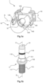
- the Fig.1a shows a high-current connector 1 with an insulating body 14.
- the insulating body 1 has a circumferential collar 148 through which a cavity 140 is formed.
- a plug contact in the form of a pin contact 11 is rotatably held about its pin axis S in the insulating body 14 .
- the insulator 14 is held on the plug contact 11 so that it can rotate about the pin axis S.
- the plug contact 11 is a high-current contact and can, for example, transmit currents of 10 A (amperes) and more.
- the plug contact could also be a socket contact, a hermaphrodite contact or any other plug contact which is able
- the plug contact could also be a socket contact, a hermaphrodite contact or any other plug contact which is able to transmit currents of, for example, 10 A and more.
- the high-current connector 1 has a locking clip 18 which is held on the peripheral collar 148 of the insulating body 14 and can be pivoted about an axis of rotation D, with the axis of rotation D running perpendicular to the axis S of the pin.
- a mating connector 4 plugged into the high-current connector 1 can be locked on the high-current connector 1 by this pivoting movement.
- the locking bracket 18 is held rotatably about the axis of rotation D on two opposite pivot pins 143 .
- the peripheral collar 148 has a polarization element in the form of a flat polarization section 146, which is provided for aligning the mating connector 4 plugged therewith.
- the circumferential collar 148 has a flat shape.
- the insulating body 14 has on its peripheral collar 148 a coding element in the form of a coding projection 145 which is directed inwards, i.e. protrudes into the cavity 140.
- the pin contact 11 is in the Fig.1b shown separately again.
- the pin axis S drawn in this illustration is formed by the axis of symmetry of the pin contact 11 .
- the pin contact 11 has in its plug-in area, which is designed as a contact pin 116, an unspecified circumferential groove in which a contact spring in the form of a ring-shaped spiral spring 118 for electrically contacting a contact socket 411 of the mating connector 4 is arranged.
- the pin contact 11 has a connection area 117 with a screw thread designed as an external thread 113 for screwing in or on a busbar, not shown in the drawing, of an electrical device or the like.
- the plug contact 11 has a plate-shaped separating collar 132 and a nut section 131.
- the latter is used, for example, for manually screwing the external thread 113 into an internal thread of the busbar using a wrench or for holding ("countering") ) of the pin contact 11 in a comparable screwing or assembly process.
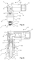
- the 2 shows another high-current connector 1 ', which largely corresponds to the aforementioned high-current connector 1, but is additionally equipped with an attachment housing 15.
- the Figure 2a shows this high-current connector 1 'in an oblique plan view.
- the Figure 2b shows it in a cross-sectional view.
- the attachment housing 15 has a hollow-cylindrical sleeve 154 into which the insulating body 145 is inserted.
- the insulating body 14 is held in the attachment housing 15 so that it can rotate about the pin axis S.
- the attachment housing 15 also has a mounting flange 156 with screw passages 150 for mounting, for example, to a device housing of the electrical device, not shown in the drawing Contraption.
- two screw nuts 13, 13′ are arranged on the external thread 113 of the connection area 117 of the pin contact 11, with which the pin contact 11 can be screwed, for example, to the busbar of the said electrical device and thereby attached to it and electrically contacted with it.
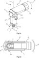
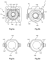
- FIGS. 3a and 3b show a high-current connector system, comprising the above-mentioned high-current connector 1' and a mating connector 4.
- the mating connector 4 is inserted with its mating mating region 441 of its mating insulating body 44, which is not visible in this representation, into the high-current connector 1' and locked with its locking pin 443 on its locking bracket 18.
- the mating connector 4 is an angled connector, i.e. it has a cable outlet 42 which is angled from its mating connector area 441.
- the cable outlet 42 is angled by 90° from the mating plug area 441, but other angular positions are also possible.
- the use of angled connectors basically has the advantage of saving space in the plug-in direction.
- the cable outlet 42 is made up of a separate retaining plate 421 and a part of the counter-insulating body 44 on the cable connection side that is angled away from the mating connector area 441.
- the insulating body 14 of the high-current connector 1 is rotatably mounted and can thus despite the attachment of the pin contact 11 and possibly the Attachment housing 15 are rotated about the plug contact axis S. Since the locking bracket 18 - not as usual on the attachment housing 15 - but on the rotatable insulating body 14 is held, the mating connector 4 with its angled cable outlet 42 can also be rotated around the plug contact axis S without any problems.
- the locking bracket 18 can be held pivotably on the mating connector 4 and can latch on the insulating body 14 of the high-current connector 1'.
- the decisive factor here is that the mating connector 4 is fixed to the insulating body 14 and not to the attachment housing 15 by the locking mechanism.
- the mating plug contact 4 has a mating plug contact in the form of a socket contact 41. This is also angled. Its plug-in area is designed as a contact socket 411 and is, as in the Figure 3b can be seen well, with the contact pin 116 of the pin contact 11 plugged.
- the mating connector 4 has a cable gland 43 on its cable outlet 42 for strain relief and sealing of a cable connected to it. This is only mentioned for the sake of completeness.
- FIGS. 3c and 3d illustrate a similar device from other perspectives for the first-mentioned high-current connector 1, which has no attachment housing 14.
- the insulating body 14 is held on the pin contact 11 only so that it can rotate.
- the pin contact 11 can be screwed to the external thread 113 of its connection area 117, for example on a busbar of the electrical device and thereby mechanically fixed thereto and electrically connected thereto.
- the insulating body 14 is held on the pin contact 11 so that it can rotate about the plug-in axis S.
- the curved double-headed arrows R, R' symbolize the respective rotational movement, i.e. rotary movement, about the plug-in contact axis S.
- the first curved double-headed arrow R shows the rotary movement that the cable outlet 42 of the mating connector can perform.
- the second curved double arrow R' symbolizes the associated rotational movement of the insulating body 14 about the plug-in contact axis S.
- the 3c shows the complete high-current connector system in the plugged and locked state in an oblique top view.
- the 3d shows the high-current connector system without the retaining plate 42 in a vertical plan view. Due to the absence of the retaining plate 42, the cable connection area 413 of the socket contact 41 can be seen
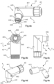
- the Fig. 4a - d show the angled mating connector 4 in different views, namely an oblique side view, a front view, a side view and an oblique top view.
- the mating connector 4 has a retaining plate 421 and a counter insulating body 44.
- counter-insulating body 44 has a counter-plug area 441 with a counter-polarization element in the form of a flat counter-polarization section 446. Opposite this counter-polarization section 446, counter-plug area 441 has a coding recess 445 as a counter-coding element.
- This has a plug contact opening 440, which in the Figure 4a the look at that The Figure 4e shows the angled socket contact 41, the cable connection area 413 is designed as a crimp connection.
- the cable connection area 413 and said contact socket 411 are arranged at right angles to one another.
- You Fig. 4f shows said holding plate 421 in a side view.
- the Figures 4g and 4h show the counter-insulating body 44 in an oblique plan view.
- the Figures 5a - 5d show different codings of the insulating body 14 of the high-current connector 1, 1 '.
- the Figure 5a shows another high-current connector 1 'with the attachment housing 15 and its mounting flange 156.
- the contact pin 116 of the pin contact 11 is covered by the contact protection 12 plugged thereon.
- the nut portion and the disk-shaped separating collar are clearly visible in this illustration.
- the pin contact 11 is attached with its thread 113 and the attachment housing 15 with its mounting flange 156 on the electrical device, not shown. The pin contact 11 and the attachment housing are therefore in a fixed position relative to one another.
- the insulating body 14, of which only the peripheral collar 148 can be seen in this illustration, has the polarization section 146 (shown at the top in the drawing) on this peripheral collar 148 and opposite the inwardly directed coding projection 145.
- the respective coding projections 145', 145" are each located on a different area of the circumferential collar 148, which then results in a different coding.
- an angular distance of 90° is also possible, as is exemplified in FIG Figures 5c and 5d is shown.
- the respective coding formation 145′, 145′′ lies on the axis of rotation D.
- a large number of other angular distances for different coding are also possible, so that a very large number of different codings are possible.
- this is implemented as follows: In the case of the high-current connector, this relative position is formed between the coding projection 145 and the polarization section 146, in the case of the mating connector between the polarization cutout 445 and the counter-polarization section 446.
- the high-current connector 1, 1' can be plugged into the mating connector 4.
- the mating connector 4 can be flexibly aligned with its angled cable outlet 42 .
Landscapes
- Connector Housings Or Holding Contact Members (AREA)
- Details Of Connecting Devices For Male And Female Coupling (AREA)
Claims (15)
- Connecteur enfichable de courant fort (1, 1'), adapté pour la transmission de plus de 25 A (ampères) en vue d'une installation et/ou d'un ajout à un rail conducteur d'un dispositif électrique, ainsi que pour l'enfichage avec un connecteur enfichable homologue (4), et pour la transmission d'énergie électrique au connecteur enfichable homologue (4), le connecteur enfichable de courant fort (1, 1') présentant :- un corps isolant (14) qui présente un élément de polarisation (146) pour définir l'alignement du connecteur enfichable homologue (4) sur le corps isolant (14) ainsi qu'un élément de codage (145) pour éviter des erreurs d'enfichage,
caractérisé par :- un contact à fiche (11) disposé dans et/ou sur le corps isolant (14) et présentant une zone d'enfichage (116) et une zone de connexion (117) à l'opposé de celle-ci, dotée d'un filetage de vis (113),- dans lequel le contact à fiche (11) peut être vissé à l'aide du filetage de vis (113) pour la fixation et la mise en contact électrique dans ou sur un rail conducteur du dispositif électrique, et- dans lequel le corps isolant (14) est en même temps maintenu sur le contact à fiche (11) en rotation autour d'un axe d'enfichage (S) du contact à fiche (11) . - Connecteur enfichable de courant fort (1') selon la revendication 1, dans lequel le connecteur enfichable de courant fort (1') présente en outre un boîtier de montage (15) qui dispose d'une bride de fixation (156) qui permet de le fixer au dispositif électrique, dans lequel le corps isolant (14) est disposé dans et/ou sur le boîtier de montage (15) et est maintenu dans et/ou sur celui-ci en rotation autour de l'axe de contact à fiche (S).
- Connecteur enfichable de courant fort (1, 1') selon l'une quelconque des revendications précédentes, dans lequel le connecteur enfichable de courant fort (1, 1') présente un étrier de verrouillage (18) qui est maintenu pivotant autour d'un axe de rotation (D) sur le corps isolant (14) du connecteur enfichable de courant fort (1, 1') pour le verrouillage et le déverrouillage du connecteur enfichable homologue (4).
- Connecteur enfichable de courant fort (1, 1') selon l'une quelconque des revendications précédentes, dans lequel le connecteur enfichable de courant fort (1, 1') dispose d'un codage qui est formé par une position relative de l'élément de codage (145) par rapport à l'élément de polarisation (146).
- Connecteur enfichable de courant fort (1, 1') selon l'une quelconque des revendications précédentes, dans lequel le corps isolant (14) présente une collerette périphérique (148) et une cavité (140) formé par celle-ci dans laquelle le contact à fiche (11) fait saillie avec sa zone enfichable (116).
- Connecteur enfichable de courant fort (1, 1') selon l'une quelconque des revendications précédentes, dans lequel le contact à fiche (11) dispose au niveau de sa zone d'enfichage (116) d'une rainure périphérique dans laquelle est disposé un ressort de contact (118) pour la mise en contact électrique d'un contact à fiche homologue (41) du connecteur enfichable homologue (4).
- Connecteur enfichable de courant fort (1, 1') selon l'une quelconque des revendications précédentes, dans lequel le contact à fiche (11) présente à une extrémité exposée de sa zone d'enfichage (116) une protection de contact (12) qui est composée d'un matériau électriquement isolant.
- Connecteur enfichable de courant fort (1, 1') selon l'une quelconque des revendications précédentes, dans lequel le contact à fiche est un contact à broche (11), et dans lequel la zone d'enfichage du contact à broche est formée par une broche de contact (116).
- Connecteur enfichable de courant fort (1, 1') selon l'une quelconque des revendications précédentes, dans lequel le connecteur enfichable de courant fort (1, 1') est réalisé de manière unipolaire.
- Système de connecteur enfichable de courant fort, présentant le connecteur enfichable de courant fort (1, 1') selon l'une quelconque des revendications précédentes et un connecteur enfichable homologue (4) pourvu d'une sortie de câble coudée (42).
- Système de connecteur enfichable de courant fort selon la revendication 10, dans lequel le connecteur enfichable de courant fort (1, 1') et le connecteur enfichable homologue (4) disposent d'un codage commun qui les définit comme étant associés l'un à l'autre et enfichable l'un dans l'autre.
- Système de connecteur enfichable de courant fort selon l'une quelconque des revendications 10 à 11, dans lequel le connecteur enfichable homologue (4) dispose d'un corps isolant homologue (44) pourvu d'un élément de polarisation homologue (446) pour l'alignement sur le corps isolant (14) du connecteur enfichable de courant fort (1).
- Système de connecteur enfichable de courant fort selon l'une quelconque des revendications 10 à 12, dans lequel, à l'état enfiché, le connecteur enfichable homologue (4) est maintenu avec sa sortie de câble coudée (42) en rotation autour de l'axe de contact à fiche (S) du connecteur enfichable de courant fort (1, 1').
- Système de connecteur enfichable de courant fort selon l'une quelconque des revendications 12 à 13, dans lequel le codage côté connecteur enfichable de courant fort est composé d'un élément rapporté de codage (145) de la collerette périphérique (148) du corps isolant (14) en relation avec sa position relative par rapport audit élément de polarisation (146), et dans lequel le codage côté connecteur enfichable homologue est composé d'un creux de codage (445), adapté audit élément de codage rapporté (145), d'un corps isolant homologue (44) du connecteur enfichable homologue (4) en relation avec sa position relative par rapport à un élément de polarisation homologue (446) du connecteur enfichable homologue (4), dans lequel le connecteur enfichable de courant fort (1, 1') et le connecteur enfichable homologue (4) sont codés de manière associée l'un à l'autre lorsque ces deux positions relatives coïncident.
- Système de connecteur enfichable de courant fort selon l'une quelconque des revendications 10 à 14, dans lequel le contact à fiche est réalisé sous forme de contact mâle (11) et le contact à fiche homologue est réalisé sous forme de contact femelle (41).
Applications Claiming Priority (2)
| Application Number | Priority Date | Filing Date | Title |
|---|---|---|---|
| DE102018127720.2A DE102018127720B3 (de) | 2018-11-07 | 2018-11-07 | Hochstromsteckverbinder und Steckverbindersystem |
| PCT/DE2019/100934 WO2020094181A1 (fr) | 2018-11-07 | 2019-10-30 | Connecteur d'alimentation haute tension et système de connecteur |
Publications (2)
| Publication Number | Publication Date |
|---|---|
| EP3878060A1 EP3878060A1 (fr) | 2021-09-15 |
| EP3878060B1 true EP3878060B1 (fr) | 2023-08-30 |
Family
ID=68542562
Family Applications (1)
| Application Number | Title | Priority Date | Filing Date |
|---|---|---|---|
| EP19802056.2A Active EP3878060B1 (fr) | 2018-11-07 | 2019-10-30 | Connecteur d'alimentation haute tension et système de connecteur |
Country Status (6)
| Country | Link |
|---|---|
| US (1) | US11424577B2 (fr) |
| EP (1) | EP3878060B1 (fr) |
| KR (1) | KR102562506B1 (fr) |
| CN (1) | CN112930627B (fr) |
| DE (1) | DE102018127720B3 (fr) |
| WO (1) | WO2020094181A1 (fr) |
Families Citing this family (6)
| Publication number | Priority date | Publication date | Assignee | Title |
|---|---|---|---|---|
| KR102633954B1 (ko) * | 2018-12-12 | 2024-02-05 | 현대자동차주식회사 | 통합형 다극 커넥터 |
| DE102020107295A1 (de) | 2020-03-17 | 2021-09-23 | Amphenol Tuchel Industrial GmbH | Berührschutzlösung |
| DE102020107396A1 (de) | 2020-03-18 | 2021-09-23 | Harting Electric Gmbh & Co. Kg | Modulares Hochstromsteckverbindersystem |
| DE102020107393A1 (de) | 2020-03-18 | 2021-09-23 | Harting Electric Gmbh & Co. Kg | Modularer Hochstromsteckverbinder |
| DE102021115707A1 (de) | 2021-06-17 | 2022-12-22 | Amphenol Tuchel Industrial GmbH | Berührschutzpin |
| DE102021133010A1 (de) | 2021-12-14 | 2023-06-15 | Amphenol Tuchel Industrial GmbH | Modularer Steckverbinder |
Citations (1)
| Publication number | Priority date | Publication date | Assignee | Title |
|---|---|---|---|---|
| DE10140177B4 (de) * | 2001-08-22 | 2006-03-09 | Ballard Power Systems Ag | Verbindungsvorrichtung |
Family Cites Families (39)
| Publication number | Priority date | Publication date | Assignee | Title |
|---|---|---|---|---|
| US4361375A (en) * | 1980-09-15 | 1982-11-30 | Switchcraft, Inc. | Miniature audio connector |
| US4500946A (en) * | 1982-01-13 | 1985-02-19 | Ford Motor Company | Replaceable lamp assembly for a sealable reflector housing |
| GB2149589B (en) * | 1983-11-08 | 1988-06-02 | Davis & Son John | A connector for releasable connection of a first to a second apparatus |
| US4840574A (en) * | 1987-11-10 | 1989-06-20 | European Atomic Energy Community (Euratom) | Multiconnector |
| US4955823A (en) * | 1989-10-10 | 1990-09-11 | Amerace Corporation | 600-Amp hot stick-operable screw and pin-and-socket assembled connector system |
| JP4168483B2 (ja) * | 1998-05-29 | 2008-10-22 | モレックス インコーポレーテッド | 電線中継方法及び電気コネクタ構造 |
| US6099342A (en) * | 1998-06-04 | 2000-08-08 | The Whitaker Corporation | Latch key mechanism |
| US6220902B1 (en) * | 1999-05-13 | 2001-04-24 | Unit Electrical Engineering Ltd. | Method and apparatus for connecting an object to a device |
| US6227914B1 (en) * | 1999-06-07 | 2001-05-08 | Monster Cable Products, Inc. | Power distribution block assembly for accommodating multiple gauge wires |
| DE10008885A1 (de) * | 2000-02-25 | 2001-08-30 | Conducta Endress & Hauser | Kupplung oder Stecker für eine Steckverbindung zur Anwendung in der Messtechnik, insbesondere in der Umweltmesstechnik |
| US6217354B1 (en) * | 2000-03-20 | 2001-04-17 | Molek Incorporated | Lever type electrical connector |
| DE20219125U1 (de) * | 2002-12-10 | 2004-04-22 | Ceag Sicherheitstechnik Gmbh | Steckverbindungsvorrichtung |
| CA2454438A1 (fr) * | 2003-02-07 | 2004-08-07 | Hypertronics Corporation | Connecteur |
| DE102004041809B4 (de) * | 2003-08-26 | 2010-09-16 | Robert Karst Gmbh & Co. Kg | Winkelkuppler |
| US6957971B2 (en) * | 2003-10-07 | 2005-10-25 | Jeng-Shyong Wu | Multiplex wire connector unit |
| JP2006040838A (ja) * | 2004-07-30 | 2006-02-09 | Yazaki Corp | 雌雄コネクタの嵌合構造 |
| JP4335102B2 (ja) * | 2004-09-03 | 2009-09-30 | 矢崎総業株式会社 | レバー嵌合式コネクタ |
| DE202006003204U1 (de) * | 2006-03-01 | 2006-05-11 | Harting Electronics Gmbh & Co. Kg | Elektrischer Kontakt |
| US7467979B2 (en) * | 2006-06-12 | 2008-12-23 | Power Feed-Thru Systems & Connectors, Llc | Apparatus and method for electrical and mechanical connection |
| US7969746B2 (en) * | 2006-09-22 | 2011-06-28 | Itt Manufacturing Enterprises, Inc. | Connection of a system module to an electronic device |
| DE102007052606B3 (de) * | 2007-11-05 | 2009-06-10 | Tyco Electronics Amp Gmbh | Elektrischer Steckverbinder, insbesondere elektrischer Stift- oder Buchsenverbinder |
| DE102008019016B4 (de) * | 2008-04-15 | 2014-12-18 | Phoenix Contact Gmbh & Co. Kg | Elektrischer Steckverbinder und Verriegelungsbügel zur Verriegelung zweier Gehäuseteile |
| DE202008014409U1 (de) * | 2008-10-29 | 2009-01-22 | Rosenberger Hochfrequenztechnik Gmbh & Co. Kg | HF-Winkelsteckverbinder |
| US20110269331A1 (en) * | 2010-05-03 | 2011-11-03 | Cooper Techologies Company | Locking Device For Connectors |
| US7931486B1 (en) * | 2010-06-26 | 2011-04-26 | Williams-Pyro, Inc. | Electrical connector for missile launch rail |
| DE102011004347A1 (de) | 2011-02-17 | 2012-08-23 | Tyco Electronics Amp Gmbh | Elektrischer Verbinder und Stecksystem |
| US9124050B2 (en) * | 2012-07-19 | 2015-09-01 | Thomas & Betts International Llc | Electrical connector having grounding mechanism |
| DE102013212233A1 (de) * | 2013-06-26 | 2014-12-31 | Zf Friedrichshafen Ag | Vorrichtung zur mechanischen und elektrischen Verbindung von Leitungsadern eines Kabels mit Leitungsanschlüssen einer elektrischen Baugruppe |
| DE202015001331U1 (de) | 2015-02-19 | 2015-04-15 | Rosenberger Hochfrequenztechnik Gmbh & Co. Kg | Steckverbinder mit Dämpfungselement |
| US10122117B2 (en) * | 2015-04-14 | 2018-11-06 | Te Connectivity Corporation | Quick connect power connector system |
| CN104779488B (zh) * | 2015-04-17 | 2017-06-06 | 四川永贵科技有限公司 | 弯式屏蔽mcu总线插头 |
| DE102015113786B4 (de) | 2015-08-20 | 2019-01-31 | Harting Electric Gmbh & Co. Kg | Steckverbinder und Verfahren zu dessen Herstellung |
| WO2017158577A1 (fr) * | 2016-03-18 | 2017-09-21 | 泰科电子(上海)有限公司 | Ensemble connecteur et ensemble d'enregistrement vidéo comprenant un ensemble connecteur |
| US9960550B2 (en) * | 2016-07-25 | 2018-05-01 | Delphi Technologies, Inc. | Coaxial connector assembly |
| JP6434938B2 (ja) * | 2016-08-10 | 2018-12-05 | 矢崎総業株式会社 | コネクタ |
| US9837761B1 (en) * | 2016-09-22 | 2017-12-05 | Te Connectivity Corporation | Electrical cable connector with rotatable housing |
| DE102017000102A1 (de) * | 2017-01-09 | 2018-07-12 | Osram Gmbh | Stecker, buchse, verbindungsstecker, leuchte und set |
| CN109950746B (zh) * | 2017-12-20 | 2020-12-22 | 番禺得意精密电子工业有限公司 | 电连接器组合 |
| TWI662218B (zh) * | 2018-06-04 | 2019-06-11 | 訊凱國際股份有限公司 | 連接頭組件 |
-
2018
- 2018-11-07 DE DE102018127720.2A patent/DE102018127720B3/de active Active
-
2019
- 2019-10-30 WO PCT/DE2019/100934 patent/WO2020094181A1/fr unknown
- 2019-10-30 CN CN201980070737.1A patent/CN112930627B/zh active Active
- 2019-10-30 KR KR1020217017168A patent/KR102562506B1/ko active IP Right Grant
- 2019-10-30 EP EP19802056.2A patent/EP3878060B1/fr active Active
- 2019-10-30 US US17/280,357 patent/US11424577B2/en active Active
Patent Citations (1)
| Publication number | Priority date | Publication date | Assignee | Title |
|---|---|---|---|---|
| DE10140177B4 (de) * | 2001-08-22 | 2006-03-09 | Ballard Power Systems Ag | Verbindungsvorrichtung |
Also Published As
| Publication number | Publication date |
|---|---|
| US11424577B2 (en) | 2022-08-23 |
| CN112930627A (zh) | 2021-06-08 |
| KR20210089216A (ko) | 2021-07-15 |
| US20220037835A1 (en) | 2022-02-03 |
| CN112930627B (zh) | 2023-05-26 |
| KR102562506B1 (ko) | 2023-08-03 |
| EP3878060A1 (fr) | 2021-09-15 |
| WO2020094181A1 (fr) | 2020-05-14 |
| DE102018127720B3 (de) | 2019-12-05 |
Similar Documents
| Publication | Publication Date | Title |
|---|---|---|
| EP3878060B1 (fr) | Connecteur d'alimentation haute tension et système de connecteur | |
| EP3061160B1 (fr) | Connecteur | |
| EP3122589B1 (fr) | Dispositif embrochable réalisé sous forme de prolongateur ou de fiche | |
| WO2017167327A1 (fr) | Dispositif de verrouillage pour connecteur électrique | |
| EP3028349B1 (fr) | Fixation de la position finale d'un système de connecteur pour augmenter la résistance aux vibrations | |
| EP3847725B1 (fr) | Connexion électrique par insertion, véhicule et procédé de verrouillage d'une connexion électrique par insertion | |
| EP1901402A1 (fr) | Connecteur solaire doté de moyens d'encliquetage améliorés | |
| EP3338326A1 (fr) | Connecteur | |
| EP3847726A1 (fr) | Connecteur électrique, jeu de câbles haute tension, système haute tension et procédé de montage d'un connecteur enfichable électrique | |
| DE102005012441B4 (de) | Elektrischer Steckverbinder sowie Verfahren zur Herstellung eines elektrischen Steckverbinders | |
| WO2019201390A1 (fr) | Module de connecteur enfichable blindé pour un connecteur enfichable industriel modulaire | |
| DE102020104510B4 (de) | Ladebuchse für ein Elektrofahrzeug | |
| DE102017119269B3 (de) | Kontaktgehäuse sowie elektrischer Verbinder | |
| WO2011157709A1 (fr) | Connecteur enfichable rapporté | |
| DE102016213757B4 (de) | Steckverbindung zum Koppeln von Hochvoltanschlüssen und System mit einer derartigen Steckverbindung | |
| EP3633802A1 (fr) | Prise de courant d'appareil, connecteur d'appareil et système de connecteur d'appareil | |
| WO2007087788A2 (fr) | Dispositif de connexion d'au moins un câble à une cosse de batterie | |
| EP3427350B1 (fr) | Un système de connecteurs, particulièrement pour conteneurs frigorifiques | |
| WO2019144988A1 (fr) | Connecteur de cartes à circuits imprimés pour transmettre des intensités de courant élevées | |
| EP1936757A2 (fr) | Système de connecteur à fiches pour un montage mural | |
| EP1986281B1 (fr) | Procédé de fabrication d'une liaison électrique conductrice | |
| DE102022004929B3 (de) | Anschlussvorrichtung zum Laden einer Hochvoltbatterie eines Fahrzeuges | |
| EP4078735B1 (fr) | Connexion électrique enfichable | |
| EP1372365B1 (fr) | Borne à connexion | |
| DE102008059000A1 (de) | Elektrischer Steckverbinder |
Legal Events
| Date | Code | Title | Description |
|---|---|---|---|
| STAA | Information on the status of an ep patent application or granted ep patent |
Free format text: STATUS: UNKNOWN |
|
| STAA | Information on the status of an ep patent application or granted ep patent |
Free format text: STATUS: THE INTERNATIONAL PUBLICATION HAS BEEN MADE |
|
| PUAI | Public reference made under article 153(3) epc to a published international application that has entered the european phase |
Free format text: ORIGINAL CODE: 0009012 |
|
| STAA | Information on the status of an ep patent application or granted ep patent |
Free format text: STATUS: REQUEST FOR EXAMINATION WAS MADE |
|
| 17P | Request for examination filed |
Effective date: 20210429 |
|
| AK | Designated contracting states |
Kind code of ref document: A1 Designated state(s): AL AT BE BG CH CY CZ DE DK EE ES FI FR GB GR HR HU IE IS IT LI LT LU LV MC MK MT NL NO PL PT RO RS SE SI SK SM TR |
|
| DAV | Request for validation of the european patent (deleted) | ||
| DAX | Request for extension of the european patent (deleted) | ||
| GRAP | Despatch of communication of intention to grant a patent |
Free format text: ORIGINAL CODE: EPIDOSNIGR1 |
|
| STAA | Information on the status of an ep patent application or granted ep patent |
Free format text: STATUS: GRANT OF PATENT IS INTENDED |
|
| INTG | Intention to grant announced |
Effective date: 20230531 |
|
| P01 | Opt-out of the competence of the unified patent court (upc) registered |
Effective date: 20230603 |
|
| GRAS | Grant fee paid |
Free format text: ORIGINAL CODE: EPIDOSNIGR3 |
|
| GRAA | (expected) grant |
Free format text: ORIGINAL CODE: 0009210 |
|
| STAA | Information on the status of an ep patent application or granted ep patent |
Free format text: STATUS: THE PATENT HAS BEEN GRANTED |
|
| AK | Designated contracting states |
Kind code of ref document: B1 Designated state(s): AL AT BE BG CH CY CZ DE DK EE ES FI FR GB GR HR HU IE IS IT LI LT LU LV MC MK MT NL NO PL PT RO RS SE SI SK SM TR |
|
| REG | Reference to a national code |
Ref country code: GB Ref legal event code: FG4D Free format text: NOT ENGLISH |
|
| REG | Reference to a national code |
Ref country code: CH Ref legal event code: EP |
|
| REG | Reference to a national code |
Ref country code: DE Ref legal event code: R096 Ref document number: 502019009189 Country of ref document: DE |
|
| REG | Reference to a national code |
Ref country code: IE Ref legal event code: FG4D Free format text: LANGUAGE OF EP DOCUMENT: GERMAN |
|
| REG | Reference to a national code |
Ref country code: LT Ref legal event code: MG9D |
|
| REG | Reference to a national code |
Ref country code: NL Ref legal event code: MP Effective date: 20230830 |
|
| PG25 | Lapsed in a contracting state [announced via postgrant information from national office to epo] |
Ref country code: GR Free format text: LAPSE BECAUSE OF FAILURE TO SUBMIT A TRANSLATION OF THE DESCRIPTION OR TO PAY THE FEE WITHIN THE PRESCRIBED TIME-LIMIT Effective date: 20231201 |
|
| PGFP | Annual fee paid to national office [announced via postgrant information from national office to epo] |
Ref country code: GB Payment date: 20231024 Year of fee payment: 5 |
|
| PG25 | Lapsed in a contracting state [announced via postgrant information from national office to epo] |
Ref country code: IS Free format text: LAPSE BECAUSE OF FAILURE TO SUBMIT A TRANSLATION OF THE DESCRIPTION OR TO PAY THE FEE WITHIN THE PRESCRIBED TIME-LIMIT Effective date: 20231230 |
|
| PG25 | Lapsed in a contracting state [announced via postgrant information from national office to epo] |
Ref country code: SE Free format text: LAPSE BECAUSE OF FAILURE TO SUBMIT A TRANSLATION OF THE DESCRIPTION OR TO PAY THE FEE WITHIN THE PRESCRIBED TIME-LIMIT Effective date: 20230830 Ref country code: RS Free format text: LAPSE BECAUSE OF FAILURE TO SUBMIT A TRANSLATION OF THE DESCRIPTION OR TO PAY THE FEE WITHIN THE PRESCRIBED TIME-LIMIT Effective date: 20230830 Ref country code: NO Free format text: LAPSE BECAUSE OF FAILURE TO SUBMIT A TRANSLATION OF THE DESCRIPTION OR TO PAY THE FEE WITHIN THE PRESCRIBED TIME-LIMIT Effective date: 20231130 Ref country code: LV Free format text: LAPSE BECAUSE OF FAILURE TO SUBMIT A TRANSLATION OF THE DESCRIPTION OR TO PAY THE FEE WITHIN THE PRESCRIBED TIME-LIMIT Effective date: 20230830 Ref country code: LT Free format text: LAPSE BECAUSE OF FAILURE TO SUBMIT A TRANSLATION OF THE DESCRIPTION OR TO PAY THE FEE WITHIN THE PRESCRIBED TIME-LIMIT Effective date: 20230830 Ref country code: IS Free format text: LAPSE BECAUSE OF FAILURE TO SUBMIT A TRANSLATION OF THE DESCRIPTION OR TO PAY THE FEE WITHIN THE PRESCRIBED TIME-LIMIT Effective date: 20231230 Ref country code: HR Free format text: LAPSE BECAUSE OF FAILURE TO SUBMIT A TRANSLATION OF THE DESCRIPTION OR TO PAY THE FEE WITHIN THE PRESCRIBED TIME-LIMIT Effective date: 20230830 Ref country code: GR Free format text: LAPSE BECAUSE OF FAILURE TO SUBMIT A TRANSLATION OF THE DESCRIPTION OR TO PAY THE FEE WITHIN THE PRESCRIBED TIME-LIMIT Effective date: 20231201 Ref country code: FI Free format text: LAPSE BECAUSE OF FAILURE TO SUBMIT A TRANSLATION OF THE DESCRIPTION OR TO PAY THE FEE WITHIN THE PRESCRIBED TIME-LIMIT Effective date: 20230830 |
|
| PGFP | Annual fee paid to national office [announced via postgrant information from national office to epo] |
Ref country code: FR Payment date: 20231026 Year of fee payment: 5 Ref country code: DE Payment date: 20231027 Year of fee payment: 5 |
|
| PG25 | Lapsed in a contracting state [announced via postgrant information from national office to epo] |
Ref country code: PL Free format text: LAPSE BECAUSE OF FAILURE TO SUBMIT A TRANSLATION OF THE DESCRIPTION OR TO PAY THE FEE WITHIN THE PRESCRIBED TIME-LIMIT Effective date: 20230830 Ref country code: NL Free format text: LAPSE BECAUSE OF FAILURE TO SUBMIT A TRANSLATION OF THE DESCRIPTION OR TO PAY THE FEE WITHIN THE PRESCRIBED TIME-LIMIT Effective date: 20230830 |
|
| PG25 | Lapsed in a contracting state [announced via postgrant information from national office to epo] |
Ref country code: ES Free format text: LAPSE BECAUSE OF FAILURE TO SUBMIT A TRANSLATION OF THE DESCRIPTION OR TO PAY THE FEE WITHIN THE PRESCRIBED TIME-LIMIT Effective date: 20230830 |
|
| PG25 | Lapsed in a contracting state [announced via postgrant information from national office to epo] |
Ref country code: SM Free format text: LAPSE BECAUSE OF FAILURE TO SUBMIT A TRANSLATION OF THE DESCRIPTION OR TO PAY THE FEE WITHIN THE PRESCRIBED TIME-LIMIT Effective date: 20230830 Ref country code: RO Free format text: LAPSE BECAUSE OF FAILURE TO SUBMIT A TRANSLATION OF THE DESCRIPTION OR TO PAY THE FEE WITHIN THE PRESCRIBED TIME-LIMIT Effective date: 20230830 Ref country code: ES Free format text: LAPSE BECAUSE OF FAILURE TO SUBMIT A TRANSLATION OF THE DESCRIPTION OR TO PAY THE FEE WITHIN THE PRESCRIBED TIME-LIMIT Effective date: 20230830 Ref country code: EE Free format text: LAPSE BECAUSE OF FAILURE TO SUBMIT A TRANSLATION OF THE DESCRIPTION OR TO PAY THE FEE WITHIN THE PRESCRIBED TIME-LIMIT Effective date: 20230830 Ref country code: DK Free format text: LAPSE BECAUSE OF FAILURE TO SUBMIT A TRANSLATION OF THE DESCRIPTION OR TO PAY THE FEE WITHIN THE PRESCRIBED TIME-LIMIT Effective date: 20230830 Ref country code: CZ Free format text: LAPSE BECAUSE OF FAILURE TO SUBMIT A TRANSLATION OF THE DESCRIPTION OR TO PAY THE FEE WITHIN THE PRESCRIBED TIME-LIMIT Effective date: 20230830 Ref country code: SK Free format text: LAPSE BECAUSE OF FAILURE TO SUBMIT A TRANSLATION OF THE DESCRIPTION OR TO PAY THE FEE WITHIN THE PRESCRIBED TIME-LIMIT Effective date: 20230830 Ref country code: PT Free format text: LAPSE BECAUSE OF FAILURE TO SUBMIT A TRANSLATION OF THE DESCRIPTION OR TO PAY THE FEE WITHIN THE PRESCRIBED TIME-LIMIT Effective date: 20240102 |