EP3877667B1 - System zum sammeln von partikeln von eisenbahnscheibenbremsen - Google Patents
System zum sammeln von partikeln von eisenbahnscheibenbremsen Download PDFInfo
- Publication number
- EP3877667B1 EP3877667B1 EP19818208.1A EP19818208A EP3877667B1 EP 3877667 B1 EP3877667 B1 EP 3877667B1 EP 19818208 A EP19818208 A EP 19818208A EP 3877667 B1 EP3877667 B1 EP 3877667B1
- Authority
- EP
- European Patent Office
- Prior art keywords
- sole
- face
- friction
- flange
- tube
- Prior art date
- Legal status (The legal status is an assumption and is not a legal conclusion. Google has not performed a legal analysis and makes no representation as to the accuracy of the status listed.)
- Active
Links
Images


Classifications
-
- F—MECHANICAL ENGINEERING; LIGHTING; HEATING; WEAPONS; BLASTING
- F16—ENGINEERING ELEMENTS AND UNITS; GENERAL MEASURES FOR PRODUCING AND MAINTAINING EFFECTIVE FUNCTIONING OF MACHINES OR INSTALLATIONS; THERMAL INSULATION IN GENERAL
- F16D—COUPLINGS FOR TRANSMITTING ROTATION; CLUTCHES; BRAKES
- F16D69/00—Friction linings; Attachment thereof; Selection of coacting friction substances or surfaces
- F16D69/04—Attachment of linings
- F16D69/0408—Attachment of linings specially adapted for plane linings
-
- F—MECHANICAL ENGINEERING; LIGHTING; HEATING; WEAPONS; BLASTING
- F16—ENGINEERING ELEMENTS AND UNITS; GENERAL MEASURES FOR PRODUCING AND MAINTAINING EFFECTIVE FUNCTIONING OF MACHINES OR INSTALLATIONS; THERMAL INSULATION IN GENERAL
- F16D—COUPLINGS FOR TRANSMITTING ROTATION; CLUTCHES; BRAKES
- F16D65/00—Parts or details
- F16D65/0031—Devices for retaining friction material debris, e.g. dust collectors or filters
-
- B—PERFORMING OPERATIONS; TRANSPORTING
- B60—VEHICLES IN GENERAL
- B60T—VEHICLE BRAKE CONTROL SYSTEMS OR PARTS THEREOF; BRAKE CONTROL SYSTEMS OR PARTS THEREOF, IN GENERAL; ARRANGEMENT OF BRAKING ELEMENTS ON VEHICLES IN GENERAL; PORTABLE DEVICES FOR PREVENTING UNWANTED MOVEMENT OF VEHICLES; VEHICLE MODIFICATIONS TO FACILITATE COOLING OF BRAKES
- B60T17/00—Component parts, details, or accessories of power brake systems not covered by groups B60T8/00, B60T13/00 or B60T15/00, or presenting other characteristic features
- B60T17/04—Arrangements of piping, valves in the piping, e.g. cut-off valves, couplings or air hoses
- B60T17/043—Brake line couplings, air hoses and stopcocks
-
- B—PERFORMING OPERATIONS; TRANSPORTING
- B60—VEHICLES IN GENERAL
- B60T—VEHICLE BRAKE CONTROL SYSTEMS OR PARTS THEREOF; BRAKE CONTROL SYSTEMS OR PARTS THEREOF, IN GENERAL; ARRANGEMENT OF BRAKING ELEMENTS ON VEHICLES IN GENERAL; PORTABLE DEVICES FOR PREVENTING UNWANTED MOVEMENT OF VEHICLES; VEHICLE MODIFICATIONS TO FACILITATE COOLING OF BRAKES
- B60T5/00—Vehicle modifications to facilitate cooling of brakes
-
- B—PERFORMING OPERATIONS; TRANSPORTING
- B61—RAILWAYS
- B61H—BRAKES OR OTHER RETARDING DEVICES SPECIALLY ADAPTED FOR RAIL VEHICLES; ARRANGEMENT OR DISPOSITION THEREOF IN RAIL VEHICLES
- B61H5/00—Applications or arrangements of brakes with substantially radial braking surfaces pressed together in axial direction, e.g. disc brakes
-
- F—MECHANICAL ENGINEERING; LIGHTING; HEATING; WEAPONS; BLASTING
- F16—ENGINEERING ELEMENTS AND UNITS; GENERAL MEASURES FOR PRODUCING AND MAINTAINING EFFECTIVE FUNCTIONING OF MACHINES OR INSTALLATIONS; THERMAL INSULATION IN GENERAL
- F16D—COUPLINGS FOR TRANSMITTING ROTATION; CLUTCHES; BRAKES
- F16D65/00—Parts or details
- F16D65/02—Braking members; Mounting thereof
- F16D65/04—Bands, shoes or pads; Pivots or supporting members therefor
- F16D65/092—Bands, shoes or pads; Pivots or supporting members therefor for axially-engaging brakes, e.g. disc brakes
- F16D65/095—Pivots or supporting members therefor
- F16D65/097—Resilient means interposed between pads and supporting members or other brake parts
- F16D65/0972—Resilient means interposed between pads and supporting members or other brake parts transmitting brake reaction force, e.g. elements interposed between torque support plate and pad
-
- F—MECHANICAL ENGINEERING; LIGHTING; HEATING; WEAPONS; BLASTING
- F16—ENGINEERING ELEMENTS AND UNITS; GENERAL MEASURES FOR PRODUCING AND MAINTAINING EFFECTIVE FUNCTIONING OF MACHINES OR INSTALLATIONS; THERMAL INSULATION IN GENERAL
- F16D—COUPLINGS FOR TRANSMITTING ROTATION; CLUTCHES; BRAKES
- F16D69/00—Friction linings; Attachment thereof; Selection of coacting friction substances or surfaces
- F16D69/04—Attachment of linings
- F16D2069/0425—Attachment methods or devices
- F16D2069/0441—Mechanical interlocking, e.g. roughened lining carrier, mating profiles on friction material and lining carrier
Definitions
- the present invention relates to the braking of railway rolling stock and in particular the friction assemblies of the braking systems of railway rolling stock.
- Such equipment we mean all vehicles configured to run on rails, such as trains, trams, metropolitan trains.
- the braking system generally comprises a disc attached to a wheel or axle of the railway rolling stock.
- the braking system further includes a friction assembly that includes a shoe carrier that supports a friction shoe.
- the friction sole usually includes means of attachment to the sole holder and a friction pad.
- the friction pad of the friction shoe comes into contact with the disc to exert a braking force on the disc.
- the friction sole slows down the disc attached to the wheel or axle.
- railway rolling stock comprises two friction assemblies, arranged on either side of the disc so as to grip, or in other words sandwich the disc to compress it on both sides.
- the rubbing pad of the friction shoe usually comprises a metallic material, such as cast iron, a sintered material or a composite material.
- a metallic material such as cast iron, a sintered material or a composite material.
- WO 2018065541 describes a friction assembly where the shoe of the sole has a collection groove open on the friction face and on an internal or external edge of the shoe, and a hole which opens into this groove and which is connected to a suction device .
- GB 2515063 describes a friction assembly where the shoe of the sole is in fluid communication with a hydraulic cylinder capable of supplying fluid to the friction face of the shoe.
- JP2005036829 describes a friction assembly where the friction face of the sole pad is in fluid communication with a suction device.
- JP2008281060 describes a friction assembly where the pad of the sole has two collection grooves which open onto the friction face of the pad and which are connected to holes passing through the sole.
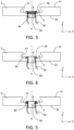
- FIG. 10 is a top view of this assembly, and the Figure 11 a cross section along line XI-XI of the Figure 10 .
- the sole holder 103 extends longitudinally in a longitudinal direction Z, and transversely in a transverse direction
- the axis perpendicular to these two faces and to the X-Z plane is a Y axis.
- the sole holder 103 has on its upper face a concave dovetail reception slide 105, which extends longitudinally from a first end of the sole holder 103 to near the second end of the sole holder 103 where this slide is non-opening.
- the sole holder 103 comprises two spaced through holes 138 on the longitudinal axis Z. Each through hole 138 connects the lower face to the bottom of the slide 105 on the upper face.
- the friction sole 102 is in two identical parts, where each part has a friction face 121 intended to be in frictional contact with the disc (not shown) of the vehicle and an opposite face 122.
- This opposite face 122 presents a profile 104 convex dovetail shape configured to cooperate with the reception slide 105.
- a first part of the sole 102 is pressed along the longitudinal axis Z by sliding the profile 104 in the slide 105, until stop of the slide 105.
- Each of the parts of the sole 102 comprises a conduit 128 oriented along the axis Y.
- each of the two conduits 128 is located opposite a hole 138.
- axis B the main axis of a conduit 128 and the hole 138 located opposite, this conduit 128 and this hole 138 therefore being coaxial.
- each conduit 128 forms, with one of the through holes 138 provided in the sole holder 103, a circuit which makes it possible to suck up particles emitted by the friction sole 102 during braking.
- a junction ring 108 consisting of a tube and a collar extending radially and outwards from this tube at one of its ends, is mounted in the hole 138.
- the tube is inserted in the hole 138, the external diameter of the tube being equal to the internal diameter of the hole 138 to ensure the best possible seal.
- the collar is housed in an annular housing of the sole holder 103, this housing being centered on the main axis B and facing the opposite face 122 of the sole 102. Thus, the collar is sandwiched between the profile of the sole 102 and the bottom of the slide 105 of the sole holder 103.
- the depth of the annular housing (along the main axis B) is substantially equal to the thickness of the flange so that once in its housing, the collar is in contact with both the sole holder 103 and the face 122 of the profile 104 of the sole 102.
- the junction ring 108 completely passes through the sole holder 103 and protrudes from it on its face opposite to its face provided with the slide 105.
- a pipe 150 On this end of the tube of the ring 108 is fixed a pipe 150 which is connected to a device suction (not shown) and which allows the suction through the conduit 128 and the hole 138 of the particles resulting from the braking of the railway vehicle.
- the junction ring 108 serves to guide the particles resulting from braking from the conduit 128 of the sole 102 towards the through hole 138 of the sole holder 3.
- the junction ring 108 therefore aims to prevent possible leaks through the conduit 128 and the hole 138.
- the junction ring 108 aims to limit the quantity of particles resulting from braking which could slip into the gap at the interface between the friction sole 102 and the sole holder 103, and especially to prevent a flow of air coming from the outside from penetrating through this gap into the hole 138, which would degrade the suction by the suction device.
- a friction assembly for a railway disc brake system for railway rolling stock comprising on the one hand a shoe holder comprising an upper face with a reception slide, and a lower face, and on the other hand at least one sole made of friction material comprising a first face which is the friction face, and a second face provided with a profile configured to cooperate with the reception slide, the sole comprising at least one conduit putting into sealed communication a first space bordered by the first face and a second space bordered by the second face, this friction assembly further comprising at least one through hole with central axis B, provided in the sole holder and located opposite one of the at least one conduit, and at least one junction ring arranged in the at least one through hole and establishing a junction with the conduit.
- such a friction assembly does not effectively prevent a passage of air at the interface between the sole 102 and the sole holder 103 at the level of the conduit 128 and the hole 138.
- the clearances at the interface between the sole holder 103 and the sole 102 prevent the junction ring 108 from ensuring sufficient sealing with the sole 102.
- the present invention aims to remedy this drawback.
- the invention aims to propose a friction assembly which makes it possible, for the same suction force, to more effectively suck up particles resulting from the braking of the railway vehicle.
- the friction assembly includes a return mechanism which is capable of pressing the at least one junction ring against the profile.
- the return mechanism is a spring.
- the return mechanism is simple to assemble in the friction assembly, and has excellent durability.
- the junction ring has a tube and a collar, the return mechanism being able to press the collar against the profile.
- the junction ring has a tube and a collar, and the spring is a helical spring bearing at one end on the collar at its other end on the sole holder.
- the junction ring has a tube and a conical flange, the flange acting as the return mechanism.
- the junction ring has a tube and a collar, and the lower face of the sole holder is provided with a cap which forms a chamber with the through hole, and the return mechanism is a helical spring surrounding the tube and taking supported at one end on the collar and at its other end on the internal face of the cap.
- the radially external periphery of the collar has a chamfer which extends along the surface of a cone of axis A.
- the profile when the profile is slid into the slide, the profile exerts a force on the chamfer which helps to automatically push the sealing ring into the hole.
- the sole comprises two conduits, and the sole holder has two through holes, each of the conduits facing one of the two through holes.
- the junction ring has a tube and a collar, the collar acting as the return mechanism, the tube extending at its end opposite the end carrying the collar by a plate which matches the underside of the sole holder.
- FIG 1 is a top view of a friction assembly 1 for a railway disc brake system for railway rolling stock, according to the invention, and the figure 2 a cross section along line II-II of the figure 1 .
- This friction assembly 1 comprises a sole holder 3 which extends in its greatest direction in a longitudinal direction Z, and transversely in a transverse direction X.
- the sole holder 3 extends mainly in the X-Z plane and comprises an upper face 31 intended to accommodate a friction sole 2, and a lower face 32 which extend parallel to this plane.
- the axis perpendicular to these two faces and to the X-Z plane is a Y axis.
- the sole holder 3 has on its upper face 31 a concave dovetail receiving slide 5, which extends longitudinally from a first end of the sole holder 3 to near the second end of the sole holder 3 where this slide 5 is non-opening.
- the sole holder 3 comprises on the longitudinal axis Z two through holes 38 spaced from one another. Each through hole 38 connects the lower face 32 to the bottom 51 of the slide 5.
- This friction assembly 1 also includes a friction sole 2.
- This friction sole 2 is in two substantially identical halves, where each half has a friction face (first face) 21 intended to be in frictional contact with the disc (not -represented) of the vehicle, and an opposite face 22 (second face).
- This opposite face 22 has a convex dovetail profile 4 configured to cooperate as closely as possible with the reception slide 5. This profile 4 extends over the entire length (in the direction Z) of the half of the sole 2.
- the face of the profile 4 which matches the bottom 51 and the sides of the slide 5 (when the profile is inserted into this slide 5) is thus a part of the opposite face 22.
- the profile 4 can have a profile different from a dovetail, and the slide 5 a profile different from a concave dovetail, provided that these two profiles are complementary and shaped to allow relative sliding of the sole 2 and the sole holder 3 along the longitudinal axis Z and prevent separation of the sole 2 from the sole holder along the Y axis.
- the region of the profile 4 around each conduit 28 and the region of the slide 5 around each hole 38 are plane in the X-Z plane and parallel.
- a first half of the sole 2 is pushed in along the longitudinal axis Z by sliding the profile 4 in the slide 5, up to the stop of the slide 5. Then the second half of the sole 2 is pushed in along the longitudinal axis Z by sliding the profile 4 in the slide 5, up to the stop of the first half of the sole 2, the contact surfaces of the first half and the second half being ideally shaped to fit over the entire their surface.
- the second face 22 of the friction sole 2, with the dovetail 4 thus matches the lower face 32 and the bottom 51 of the slide of the sole holder 3.
- Each of the halves of the sole 2 comprises a conduit 28 (also called “pneumatic conduit”) oriented along the Y axis.
- This conduit 28 places in sealed communication a first space E1 bordered by a first face 21 of the sole 2 and a second space E2 bordered by a second face 22 of the friction sole 2 opposite said first face 21 and forming the face of the profile 4.
- each of the two conduits 28 is located opposite one of the holes 38.
- axis A the main axis of a conduit 28 and of the hole 38 located opposite, this conduit 28 and this hole 38 therefore being coaxial (there are therefore two parallel main axes A, one for each set of a conduit 28 and a hole 38).
- each conduit 28 forms, with one of the through holes 38 provided in the sole holder 3, a circuit which makes it possible to suck up particles emitted by the friction sole 2 during braking.
- conduit 28 and the hole 38 are coaxial with main axis A.
- conduit 28 can be inclined relative to axis A, from the interface between hole 38 and conduit 28 (the orifice of conduit 28 opening at this interface is centered on axis A).
- the conduit 28 can alternatively be inclined relative to the axis A of the hole 38.
- conduit 28 and the hole 38 are facing each other, which means that the orifice of the conduit 28 opening at this interface matches the hole 38, such that the conduit 28 extends the hole 38.
- the sole 28 has been described above as consisting of two identical halves. Alternatively, the sole 28 is in one piece and of shape and dimension identical to that of these two halves joined side by side as in use.
- the single sole 28 then comprises two conduits 28, or a single conduit 28, or more than two conduits 28.
- a junction ring 8 consisting of a tube 81 and a collar 82 extending radially perpendicular to the main axis A and outwards from this tube 81 at one of its ends, is mounted in each of the holes 38.
- the Figure 6 is a perspective view of such a junction ring 8.
- Ring 8 is therefore coaxial with hole 38.
- the tube 81 of the junction ring 8 completely passes through the sole holder 3 and protrudes from it on its lower face 32.
- a pipe 50 which is connected to a suction mechanism (not shown ). Pipe 50 allows the suction through the conduit 28 and the hole 38 of the particles resulting from the braking of the railway vehicle.
- the junction ring 8 serves to guide the particles resulting from braking from the conduit 28 of the sole 2 towards the through hole 38 of the sole holder 3.
- the orifice of the conduit 28 is opposite the hole of the tube 81 and centered on this tube 81.
- the radially outer periphery of the collar 82 has a chamfer 83.
- the chamfer 83 extends along the surface of a cone with central axis A, the collar 82 being located between the top of this cone and the tube 81.
- the tube 81 is inserted into the hole 38, the external diameter of the tube 81 being equal or substantially equal to the internal diameter of the hole 38 in order to ensure the best possible seal between the tube 81 and the wall of the hole 38, while allowing a sliding of the tube 81 along the main axis A relative to the sole holder 3.
- the collar 82 is housed in an annular housing 39 of the sole holder 3.
- This housing 39 is a cavity in the bottom of the slide 5 and is centered on the main axis A.
- the housing 39 faces face 22 of profile 4, as illustrated in figure 2 .
- a return mechanism 90 is housed which tends to move the collar 82 away from this housing base 39.
- the return mechanism 90 is a helical spring which is centered on the main axis A.
- the Figure 3 shows this spring at rest.
- the collar 82 pushed upwards by the spring, then protrudes above the bottom of the slide 5.
- flange 82 does not have a chamfer 83, it is necessary to push (for example manually) the ring 8 into the housing 39 until the flange 82 no longer protrudes from the bottom of the slide 5, in order to be able to continue to slide profile 4 in slide 5.
- junction ring 8 thus prevents possible leaks through the conduit 28 and the hole 38.
- the junction ring 8 makes it possible to limit the quantity of particles resulting from braking likely to slip into the gap at the interface between the friction sole 2 and the sole holder 3.
- the junction ring 8 above all makes it possible to prevent air from penetrating through this gap into the hole 38, which would reduce the effectiveness of the suction by the device suction.
- the return mechanism 90 can be of any type, provided that it presses the flange 82 against the profile 4 when the profile 4 covers the flange 82.
- the return mechanism 90 is the collar 82 which is shaped like an annular spring (of the “Belleville washer” type), as illustrated in Figure 4 .
- the collar 82 extends, from the end of the tube 81, substantially along the surface of a cone with central axis A, the tube 81 being located in the space delimited by this cone.
- the collar 82 is flat (as in the previous embodiment in figure 2 And 3 ), and the return mechanism 90 is an elastic annular seal which is housed in the housing 39 between the flange 82 and the bottom of the housing 39.
- the Figure 5 shows this joint at rest. The collar 82, pushed upwards by the seal, then protrudes above the bottom of the slide 5.
- the lower face 32 of the sole holder 3 is provided with an annular cap 70 centered on the central axis A.
- the cap 70 is provided in its center with a central orifice 75.
- the radially outer edge 72 of this cap 70 is fixed on the lower face 32.
- the tube 81 passes through the orifice 75, the diameter of which is equal to the external diameter of the tube 81 so as to establish a seal between the tube 81 and the cap 70.
- the return mechanism 90 is a helical spring which is centered on the main axis A, one end of which rests on the collar 82 (which is flat) and the other end of which presses on the cap 70 such that the spring tends to push the collar 82 upwards and make it protrude above the bottom of the slide 5.
- the tube 81 has on its external face a radial projection 815 which abuts against the cap 70 so as to prevent the tube 81 from sliding out of the cap 70 under the action of the spring.
- the tube 81 is long enough so that, when the spring is at rest, the tube 81 is always in contact with the cap 70 and protrudes below this cap 70 to allow the attachment of the pipe 50 to the end of the tube 81 .
- FIG. 7 shows the spring in compression, in the configuration where the profile 4 is inserted in the slide 5 above the hole 38. The spring then presses the collar 82 against the profile 4.
- the dimensions (and in particular the diameter) of the collar 82 are chosen so that, once the profile 4 is inserted into the slide 5 above the hole 38, the collar 82 is in contact with the internal face of the hole 38, or of the housing 39 if necessary. This contributes to the overall seal between hole 38 and conduit 28.
- the space delimited by the through hole 38 and the cap 70 constitutes a chamber, and when the ring 8 is held against the profile 4, this chamber is sealed with only those of the tube 8 as orifices. This contributes to the sealing overall between hole 38 and conduit 28.
- the cap 70 has been described above as covering a single hole 38.
- the cap 70 can have an oblong shape in order to cover these two holes.
- the geometry of the cap 70 around each of the holes 38, and the geometry of each ring 8, are as illustrated in Figure 7 .
- the cap 70 therefore has two orifices 75, each crossed by a ring 8.
- the cap 70 has a single orifice 75 on which the pipe 50 is fixed.
- Each of the two rings 8 (one per hole 38) then opens into the oblong chamber delimited by the cap 70.
- the cap 70 then has two internal protrusions on which each spring 90 rests, these protrusions also serving to limit the travel (upwards in the figures) of the spring 90.
- the junction ring 8 has a tube 81 and a collar 82.
- the collar 82 is shaped to act as the return mechanism 90.
- the collar 82 has at its radially outer end a lip which folds towards the tube 81 When the sole 2 presses on the ring 8 along the axis A, the lip deforms in order to fill the housing 39, thus ensuring sealing with the sole 2.
- the tube 81 extends at its end opposite the end carrying the collar 82 by a plate 84 which matches the lower face 32 of the sole holder 3.
- the plate 84 is thus in support on the lower face 32.
- the ring 8 is held in place in the hole 38 thanks to the plate 84.
- the lower face 32 of the sole holder 3 is provided with a cap 70 which is fixed on this lower face 32 and which surrounds the plate 84.
- the cap 70 is provided with an orifice on which the pipe 50 is fixed so waterproof. The cap 70 thus delimits a room.
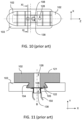
- the plate 84 instead of carrying a single junction ring 8, carries two junction rings 8.
- the tube 81 of each of the rings 8 extends at its end opposite the end carrying the collar 82 by the plate 84 .
- the sole 3 is shown in perspective and in longitudinal section (in the vertical plane Y-Z) in its middle, that is to say in the middle of the slide 5.
- the assembly of the plate 84 and the junction rings 8 is represented in exploded perspective.
- the two rings 8 are intended to be inserted into the holes 38 along the main axes A, in the direction of the vertical axis Y.
- the plate 84 can carry two rings 8, or more depending on the total number of holes 38 in the sole holder 3.
- the return mechanism 90 which presses the ring 8 against the profile 4 is produced by two elements which attract each other at a distance.
- this attraction is magnetic.
- the collar 82 of the ring 8 comprises an annular magnet (or a plurality of magnets distributed over its circumference) which constitutes the first of the two elements.
- the region of the second face 22 of the profile 4 around the conduit 28 constitutes the second of the two elements when the profile is made of steel.
- the magnetic field of attraction between the magnet of the flange 82 and the profile 4 presses the flange 82 against the profile 4.
- the profile 4 is made of a material which is not ferromagnetic, we insert a ring magnet around conduit 28, this magnet then constituting the second of the two elements.
Landscapes
- Engineering & Computer Science (AREA)
- Mechanical Engineering (AREA)
- General Engineering & Computer Science (AREA)
- Transportation (AREA)
- Braking Arrangements (AREA)
Claims (9)
- Reibanordnung (1) für ein Eisenbahn-Scheibenbremsensystem für Eisenbahn-Schienenfahrzeuge, wobei die Reibanordnung (1) einerseits einen Belaghalter (3), welcher eine obere Fläche (31) mit einem Aufnahmeschlitten (5) und eine untere Fläche (32) umfasst, und andererseits wenigstens einen Belag (2) aus Reibmaterial umfasst, welcher eine erste Fläche (21), welche die Reibfläche ist, und eine zweite Fläche (22) umfasst, welcher mit einem Profil (4) versehen ist, welches dazu eingerichtet ist, mit dem Aufnahmeschlitten (5) zusammenzuwirken, wobei der Belag (2) wenigstens eine Leitung (28) umfasst, welche einen ersten Raum (E1), welcher durch die erste Fläche (21) begrenzt ist, und einen zweiten Raum (E2), welcher durch die zweite Fläche (22) begrenzt ist, in abgedichtete Kommunikation versetzt, wobei die Reibanordnung (1) ferner wenigstens Durchgangsloch (38) mit Mittelachse A umfasst, welches in dem Belaghalter (3) gebildet und gegenüber der wenigstens einen Leitung (28) angeordnet ist, sowie wenigstens einen Verbindungsring (8), welcher in dem wenigstens einen Durchgangsloch (38) aufgenommen ist und eine Verbindung mit der wenigstens einen Leitung (28) herstellt, wobei die Reibanordnung (1) dadurch gekennzeichnet ist, dass sie einen Rückstellmechanismus (90) umfasst, welcher dazu in der Lage ist, den wenigstens einen Verbindungsring (8) gegen das Profil (4) zu pressen.
- Reibanordnung (1) nach Anspruch 1, dadurch gekennzeichnet, dass der Rückstellmechanismus (90) eine Feder ist.
- Reinanordnung (1) nach Anspruch 1 oder 2, dadurch gekennzeichnet, dass der Verbindungsring (8) ein Rohr (81) und einen Kragen (82) aufweist, wobei der Rückstellmechanismus (90) dazu in der Lage ist, den Kragen (82) gegen das Profil (4) zu pressen.
- Reibanordnung (1) nach Anspruch 2, dadurch gekennzeichnet, dass der Ring (8) ein Rohr (81) und einen Kragen (82) aufweist und die Feder eine Schraubenfeder ist, welche an einem Ende an dem Kragen (82) und an ihrem anderen Ende an dem Belaghalter (3) anliegt.
- Reibanordnung (1) nach Anspruch 3, dadurch gekennzeichnet, dass der Ring (8) ein Rohr (81) und einen konischen Kragen (82) aufweist, wobei der Kragen (82) als der Rückstellmechanismus (90) wirkt.
- Reibanordnung (1) nach Anspruch 2 oder 3, dadurch gekennzeichnet, dass der Ring (8) ein Rohr (81) und einen Kragen (82) aufweist, dass die untere Fläche (32) des Belaghalters (3) mit einer Kappe (70) versehen ist, welche mit dem Durchgangsloch (38) eine Kammer bildet, und dass der Rückstellmechanismus (90) eine Schraubenfeder ist, welche das Rohr (81) umgibt und an einem Ende an dem Kragen (82) und an ihrem anderen Ende an der inneren Fläche der Kappe (70) anliegt.
- Reibanordnung (1) nach einem der Ansprüche 3 bis 6, dadurch gekennzeichnet, dass der äußere radiale Umfang des Kragens (82) eine Abschrägung (83) aufweist, welche sich entlang der Fläche eines Kegels mit Mittelachse A erstreckt.
- Reibanordnung (1) nach einem der vorhergehenden Ansprüche, dadurch gekennzeichnet, dass der Belag (2) zwei Leitungen (28) umfasst und der Belaghalter (3) zwei Durchgangslöcher (38) umfasst, wobei jede der Leitungen (28) einem der beiden Durchgangslöcher (38) gegenüberliegt.
- Reibanordnung nach Anspruch 1, dadurch gekennzeichnet, dass der Verbindungsring (8) ein Rohr (81) und einen Kragen (82) aufweist, wobei der Kragen (82) als der Rückstellmechanismus (90) wirkt, wobei sich das Rohr (81) an seinem Ende gegenüber dem Ende, welches den Kragen (82) trägt, durch eine Platte (84) erstreckt, welche zu der unteren Fläche (32) des Belaghalters (3) passt.
Applications Claiming Priority (2)
| Application Number | Priority Date | Filing Date | Title |
|---|---|---|---|
| FR1860320A FR3088394B1 (fr) | 2018-11-08 | 2018-11-08 | Systeme de captation de particules de frein a disque ferroviaire avec bague d'etancheite et mecanisme de rappel |
| PCT/FR2019/052608 WO2020094962A1 (fr) | 2018-11-08 | 2019-11-04 | Systeme de captation de particules de frein a disque ferroviaire |
Publications (2)
| Publication Number | Publication Date |
|---|---|
| EP3877667A1 EP3877667A1 (de) | 2021-09-15 |
| EP3877667B1 true EP3877667B1 (de) | 2024-03-27 |
Family
ID=65494403
Family Applications (1)
| Application Number | Title | Priority Date | Filing Date |
|---|---|---|---|
| EP19818208.1A Active EP3877667B1 (de) | 2018-11-08 | 2019-11-04 | System zum sammeln von partikeln von eisenbahnscheibenbremsen |
Country Status (8)
| Country | Link |
|---|---|
| US (1) | US11852199B2 (de) |
| EP (1) | EP3877667B1 (de) |
| JP (1) | JP7539712B2 (de) |
| KR (1) | KR102727011B1 (de) |
| CN (1) | CN113242941B (de) |
| FR (1) | FR3088394B1 (de) |
| SG (1) | SG11202104400TA (de) |
| WO (1) | WO2020094962A1 (de) |
Families Citing this family (6)
| Publication number | Priority date | Publication date | Assignee | Title |
|---|---|---|---|---|
| FR3088394B1 (fr) * | 2018-11-08 | 2020-11-20 | Tallano Tech | Systeme de captation de particules de frein a disque ferroviaire avec bague d'etancheite et mecanisme de rappel |
| FR3098178B1 (fr) * | 2019-07-03 | 2021-07-30 | Tallano Tech | Système de sécurisation de pièce montée sur porte-semelle |
| FR3125267B1 (fr) | 2021-07-16 | 2023-07-28 | Tallano Tech | Ensemble à friction avec bloc connecteur et circuit d’aspiration |
| FR3125266B1 (fr) | 2021-07-16 | 2023-06-16 | Tallano Tech | Bague d’étanchéité avec blocage en translation |
| FR3131945B1 (fr) | 2022-01-14 | 2024-03-29 | Tallano Tech | Semelle avec surface d’appui pour bague d’étanchéité |
| JP7662711B2 (ja) | 2023-07-05 | 2025-04-15 | ナブテスコ株式会社 | ユニットブレーキ装置の制輪子取付構造及びユニットブレーキ装置の制輪子 |
Family Cites Families (20)
| Publication number | Priority date | Publication date | Assignee | Title |
|---|---|---|---|---|
| FR2681925B1 (fr) * | 1991-10-01 | 1997-09-05 | Flertex Sa | Plaquette de frein a disque pour chemin de fer. |
| FR2704035B1 (fr) * | 1993-04-15 | 1995-06-09 | Alliedsignal Europ Services | Ensemble d'un element de friction equipe d'un ressort pour frein a disque. |
| DE19643869C2 (de) * | 1996-10-30 | 2001-10-18 | Wolfgang Foesel | Bremsanlage für ein Kraftfahrzeug |
| JP2005036829A (ja) * | 2003-07-15 | 2005-02-10 | Mitsubishi Electric Corp | 摩擦式ブレーキ装置 |
| JP2008281060A (ja) * | 2007-05-09 | 2008-11-20 | Toyota Motor Corp | ブレーキパッド |
| CN201800690U (zh) | 2010-08-19 | 2011-04-20 | 常州市铁马科技实业有限公司 | 铁路车辆用盘式停放制动装置 |
| GB201110515D0 (en) * | 2011-06-22 | 2011-08-03 | Meritor Heavy Vehicle Braking | A force transmission device |
| DE102011111594A1 (de) * | 2011-08-25 | 2013-02-28 | Audi Ag | Verfahren zum Bremsen eines Kraftfahrzeugs |
| GB2492858C2 (en) * | 2011-12-06 | 2014-12-10 | Trevor Michael Mennie | Brake system |
| GB2515063A (en) * | 2012-03-02 | 2014-12-17 | Trevor Michael Mennie | Brake system |
| WO2014199129A1 (en) * | 2013-06-12 | 2014-12-18 | Mennie Trevor Michael | Brake pad assembly |
| EP3051165B1 (de) * | 2015-01-28 | 2019-05-29 | Meritor Heavy Vehicle Braking Systems (UK) Limited | Scheibenbremse |
| DE102015109034A1 (de) * | 2015-06-09 | 2016-12-15 | Federal-Mogul Bremsbelag Gmbh | Flexible Lagerung von Reibbelagelementen in Bremsbelägen |
| DE102015109033A1 (de) * | 2015-06-09 | 2016-12-15 | Federal-Mogul Bremsbelag Gmbh | Anordnung von Reibbelagelementen in Bremsbelägen zur Erhöhung einer Kontaktkraft zwischen den Reibbelagelementen bei Bremsbetätigung |
| EP3374657B1 (de) * | 2015-11-10 | 2024-01-03 | Performance Friction Corporation | Bremsbelag mit einem bremsbelagtaktungs- und -rückzugsteuergerät mit sperrverbindung |
| FR3046644B1 (fr) * | 2016-01-13 | 2019-04-12 | Tallano Technologie | Ensemble de frein a captation de particules avec deflecteur |
| DE102016117778A1 (de) * | 2016-09-21 | 2018-03-22 | Knorr-Bremse Systeme für Nutzfahrzeuge GmbH | Trommelbremse |
| FR3057040B1 (fr) | 2016-10-05 | 2019-05-03 | Tallano Technologie | Plaquette de frein et ensemble de frein a captation de particules |
| FR3069831B1 (fr) * | 2017-08-01 | 2019-09-13 | Tallano Technologie | Ensemble a friction pour systeme de freinage ferroviaire |
| FR3088394B1 (fr) * | 2018-11-08 | 2020-11-20 | Tallano Tech | Systeme de captation de particules de frein a disque ferroviaire avec bague d'etancheite et mecanisme de rappel |
-
2018
- 2018-11-08 FR FR1860320A patent/FR3088394B1/fr active Active
-
2019
- 2019-11-04 SG SG11202104400TA patent/SG11202104400TA/en unknown
- 2019-11-04 JP JP2021524434A patent/JP7539712B2/ja active Active
- 2019-11-04 CN CN201980075145.9A patent/CN113242941B/zh active Active
- 2019-11-04 EP EP19818208.1A patent/EP3877667B1/de active Active
- 2019-11-04 KR KR1020217013563A patent/KR102727011B1/ko active Active
- 2019-11-04 US US17/291,460 patent/US11852199B2/en active Active
- 2019-11-04 WO PCT/FR2019/052608 patent/WO2020094962A1/fr not_active Ceased
Also Published As
| Publication number | Publication date |
|---|---|
| US11852199B2 (en) | 2023-12-26 |
| FR3088394B1 (fr) | 2020-11-20 |
| JP2022506825A (ja) | 2022-01-17 |
| EP3877667A1 (de) | 2021-09-15 |
| JP7539712B2 (ja) | 2024-08-26 |
| CN113242941A (zh) | 2021-08-10 |
| SG11202104400TA (en) | 2021-05-28 |
| CN113242941B (zh) | 2023-03-10 |
| WO2020094962A1 (fr) | 2020-05-14 |
| US20220003291A1 (en) | 2022-01-06 |
| FR3088394A1 (fr) | 2020-05-15 |
| KR20210075122A (ko) | 2021-06-22 |
| KR102727011B1 (ko) | 2024-11-05 |
| CA3116399A1 (fr) | 2020-05-14 |
Similar Documents
| Publication | Publication Date | Title |
|---|---|---|
| EP3877667B1 (de) | System zum sammeln von partikeln von eisenbahnscheibenbremsen | |
| EP3661818B1 (de) | Scheinenfahrzeugbremssystembremsbelag | |
| EP3662171B1 (de) | Scheibenbremsbelag | |
| FR3075103B1 (fr) | Dispositif de butee de suspension et jambe de force equipee d’un tel dispositif | |
| EP3642091B1 (de) | Bremssystem für schienenfahrzeuge | |
| CA3143067C (fr) | Systeme de securisation de piece montee sur porte-semelle | |
| FR3125267A1 (fr) | Ensemble à friction avec bloc connecteur et circuit d’aspiration | |
| CA3116399C (fr) | Systeme de captation de particules de frein a disque ferroviaire | |
| EP1900960B1 (de) | Bremsbelag | |
| EP4370387B1 (de) | Dichtring mit verriegelung gegen translatorische bewegung | |
| FR3131945A1 (fr) | Semelle avec surface d’appui pour bague d’étanchéité | |
| EP2186632A1 (de) | Mounting system for sliding punches in a tablet press | |
| CA2389485C (fr) | Dispositif de clapet de refoulement pour compresseur de fluide | |
| FR3120103A1 (fr) | Dispositif de freinage a recuperation de particules magnetiques au freinage a canalisation optimisee desdites particules magnetiques | |
| FR3124783A1 (fr) | Ensemble bague d’appui pour essieux ferroviaires | |
| FR3120104A1 (fr) | Dispositif de freinage a recuperation de particules magnetiques au freinage comportant un aimant de recuperation interchangeable | |
| FR2744496A1 (fr) | Pompe oleohydraulique |
Legal Events
| Date | Code | Title | Description |
|---|---|---|---|
| STAA | Information on the status of an ep patent application or granted ep patent |
Free format text: STATUS: UNKNOWN |
|
| STAA | Information on the status of an ep patent application or granted ep patent |
Free format text: STATUS: THE INTERNATIONAL PUBLICATION HAS BEEN MADE |
|
| PUAI | Public reference made under article 153(3) epc to a published international application that has entered the european phase |
Free format text: ORIGINAL CODE: 0009012 |
|
| STAA | Information on the status of an ep patent application or granted ep patent |
Free format text: STATUS: REQUEST FOR EXAMINATION WAS MADE |
|
| 17P | Request for examination filed |
Effective date: 20210510 |
|
| AK | Designated contracting states |
Kind code of ref document: A1 Designated state(s): AL AT BE BG CH CY CZ DE DK EE ES FI FR GB GR HR HU IE IS IT LI LT LU LV MC MK MT NL NO PL PT RO RS SE SI SK SM TR |
|
| DAV | Request for validation of the european patent (deleted) | ||
| DAX | Request for extension of the european patent (deleted) | ||
| STAA | Information on the status of an ep patent application or granted ep patent |
Free format text: STATUS: EXAMINATION IS IN PROGRESS |
|
| 17Q | First examination report despatched |
Effective date: 20220607 |
|
| REG | Reference to a national code |
Ref country code: DE Ref legal event code: R079 Free format text: PREVIOUS MAIN CLASS: F16D0065000000 Ipc: B60T0005000000 Ref document number: 602019049137 Country of ref document: DE |
|
| RIC1 | Information provided on ipc code assigned before grant |
Ipc: F16D 65/00 20060101ALI20230912BHEP Ipc: F16D 69/04 20060101ALI20230912BHEP Ipc: B61H 5/00 20060101ALI20230912BHEP Ipc: B60T 17/04 20060101ALI20230912BHEP Ipc: B60T 5/00 20060101AFI20230912BHEP |
|
| GRAP | Despatch of communication of intention to grant a patent |
Free format text: ORIGINAL CODE: EPIDOSNIGR1 |
|
| STAA | Information on the status of an ep patent application or granted ep patent |
Free format text: STATUS: GRANT OF PATENT IS INTENDED |
|
| INTG | Intention to grant announced |
Effective date: 20231023 |
|
| P01 | Opt-out of the competence of the unified patent court (upc) registered |
Effective date: 20231201 |
|
| GRAS | Grant fee paid |
Free format text: ORIGINAL CODE: EPIDOSNIGR3 |
|
| GRAA | (expected) grant |
Free format text: ORIGINAL CODE: 0009210 |
|
| STAA | Information on the status of an ep patent application or granted ep patent |
Free format text: STATUS: THE PATENT HAS BEEN GRANTED |
|
| AK | Designated contracting states |
Kind code of ref document: B1 Designated state(s): AL AT BE BG CH CY CZ DE DK EE ES FI FR GB GR HR HU IE IS IT LI LT LU LV MC MK MT NL NO PL PT RO RS SE SI SK SM TR |
|
| RAP3 | Party data changed (applicant data changed or rights of an application transferred) |
Owner name: TALLANO TECHNOLOGIES |
|
| REG | Reference to a national code |
Ref country code: GB Ref legal event code: FG4D Free format text: NOT ENGLISH |
|
| REG | Reference to a national code |
Ref country code: CH Ref legal event code: EP |
|
| REG | Reference to a national code |
Ref country code: DE Ref legal event code: R096 Ref document number: 602019049137 Country of ref document: DE |
|
| REG | Reference to a national code |
Ref country code: IE Ref legal event code: FG4D Free format text: LANGUAGE OF EP DOCUMENT: FRENCH |
|
| PG25 | Lapsed in a contracting state [announced via postgrant information from national office to epo] |
Ref country code: LT Free format text: LAPSE BECAUSE OF FAILURE TO SUBMIT A TRANSLATION OF THE DESCRIPTION OR TO PAY THE FEE WITHIN THE PRESCRIBED TIME-LIMIT Effective date: 20240327 |
|
| REG | Reference to a national code |
Ref country code: LT Ref legal event code: MG9D |
|
| PG25 | Lapsed in a contracting state [announced via postgrant information from national office to epo] |
Ref country code: GR Free format text: LAPSE BECAUSE OF FAILURE TO SUBMIT A TRANSLATION OF THE DESCRIPTION OR TO PAY THE FEE WITHIN THE PRESCRIBED TIME-LIMIT Effective date: 20240628 |
|
| PG25 | Lapsed in a contracting state [announced via postgrant information from national office to epo] |
Ref country code: HR Free format text: LAPSE BECAUSE OF FAILURE TO SUBMIT A TRANSLATION OF THE DESCRIPTION OR TO PAY THE FEE WITHIN THE PRESCRIBED TIME-LIMIT Effective date: 20240327 Ref country code: RS Free format text: LAPSE BECAUSE OF FAILURE TO SUBMIT A TRANSLATION OF THE DESCRIPTION OR TO PAY THE FEE WITHIN THE PRESCRIBED TIME-LIMIT Effective date: 20240627 |
|
| PG25 | Lapsed in a contracting state [announced via postgrant information from national office to epo] |
Ref country code: RS Free format text: LAPSE BECAUSE OF FAILURE TO SUBMIT A TRANSLATION OF THE DESCRIPTION OR TO PAY THE FEE WITHIN THE PRESCRIBED TIME-LIMIT Effective date: 20240627 Ref country code: NO Free format text: LAPSE BECAUSE OF FAILURE TO SUBMIT A TRANSLATION OF THE DESCRIPTION OR TO PAY THE FEE WITHIN THE PRESCRIBED TIME-LIMIT Effective date: 20240627 Ref country code: LT Free format text: LAPSE BECAUSE OF FAILURE TO SUBMIT A TRANSLATION OF THE DESCRIPTION OR TO PAY THE FEE WITHIN THE PRESCRIBED TIME-LIMIT Effective date: 20240327 Ref country code: HR Free format text: LAPSE BECAUSE OF FAILURE TO SUBMIT A TRANSLATION OF THE DESCRIPTION OR TO PAY THE FEE WITHIN THE PRESCRIBED TIME-LIMIT Effective date: 20240327 Ref country code: GR Free format text: LAPSE BECAUSE OF FAILURE TO SUBMIT A TRANSLATION OF THE DESCRIPTION OR TO PAY THE FEE WITHIN THE PRESCRIBED TIME-LIMIT Effective date: 20240628 Ref country code: FI Free format text: LAPSE BECAUSE OF FAILURE TO SUBMIT A TRANSLATION OF THE DESCRIPTION OR TO PAY THE FEE WITHIN THE PRESCRIBED TIME-LIMIT Effective date: 20240327 Ref country code: BG Free format text: LAPSE BECAUSE OF FAILURE TO SUBMIT A TRANSLATION OF THE DESCRIPTION OR TO PAY THE FEE WITHIN THE PRESCRIBED TIME-LIMIT Effective date: 20240327 |
|
| REG | Reference to a national code |
Ref country code: NL Ref legal event code: MP Effective date: 20240327 |
|
| PG25 | Lapsed in a contracting state [announced via postgrant information from national office to epo] |
Ref country code: SE Free format text: LAPSE BECAUSE OF FAILURE TO SUBMIT A TRANSLATION OF THE DESCRIPTION OR TO PAY THE FEE WITHIN THE PRESCRIBED TIME-LIMIT Effective date: 20240327 Ref country code: LV Free format text: LAPSE BECAUSE OF FAILURE TO SUBMIT A TRANSLATION OF THE DESCRIPTION OR TO PAY THE FEE WITHIN THE PRESCRIBED TIME-LIMIT Effective date: 20240327 |
|
| PG25 | Lapsed in a contracting state [announced via postgrant information from national office to epo] |
Ref country code: NL Free format text: LAPSE BECAUSE OF FAILURE TO SUBMIT A TRANSLATION OF THE DESCRIPTION OR TO PAY THE FEE WITHIN THE PRESCRIBED TIME-LIMIT Effective date: 20240327 |
|
| REG | Reference to a national code |
Ref country code: AT Ref legal event code: MK05 Ref document number: 1669621 Country of ref document: AT Kind code of ref document: T Effective date: 20240327 |
|
| PG25 | Lapsed in a contracting state [announced via postgrant information from national office to epo] |
Ref country code: NL Free format text: LAPSE BECAUSE OF FAILURE TO SUBMIT A TRANSLATION OF THE DESCRIPTION OR TO PAY THE FEE WITHIN THE PRESCRIBED TIME-LIMIT Effective date: 20240327 |
|
| PG25 | Lapsed in a contracting state [announced via postgrant information from national office to epo] |
Ref country code: IS Free format text: LAPSE BECAUSE OF FAILURE TO SUBMIT A TRANSLATION OF THE DESCRIPTION OR TO PAY THE FEE WITHIN THE PRESCRIBED TIME-LIMIT Effective date: 20240727 |
|
| PG25 | Lapsed in a contracting state [announced via postgrant information from national office to epo] |
Ref country code: SM Free format text: LAPSE BECAUSE OF FAILURE TO SUBMIT A TRANSLATION OF THE DESCRIPTION OR TO PAY THE FEE WITHIN THE PRESCRIBED TIME-LIMIT Effective date: 20240327 Ref country code: PT Free format text: LAPSE BECAUSE OF FAILURE TO SUBMIT A TRANSLATION OF THE DESCRIPTION OR TO PAY THE FEE WITHIN THE PRESCRIBED TIME-LIMIT Effective date: 20240729 |
|
| PG25 | Lapsed in a contracting state [announced via postgrant information from national office to epo] |
Ref country code: ES Free format text: LAPSE BECAUSE OF FAILURE TO SUBMIT A TRANSLATION OF THE DESCRIPTION OR TO PAY THE FEE WITHIN THE PRESCRIBED TIME-LIMIT Effective date: 20240327 |
|
| PG25 | Lapsed in a contracting state [announced via postgrant information from national office to epo] |
Ref country code: CZ Free format text: LAPSE BECAUSE OF FAILURE TO SUBMIT A TRANSLATION OF THE DESCRIPTION OR TO PAY THE FEE WITHIN THE PRESCRIBED TIME-LIMIT Effective date: 20240327 Ref country code: EE Free format text: LAPSE BECAUSE OF FAILURE TO SUBMIT A TRANSLATION OF THE DESCRIPTION OR TO PAY THE FEE WITHIN THE PRESCRIBED TIME-LIMIT Effective date: 20240327 |
|
| PG25 | Lapsed in a contracting state [announced via postgrant information from national office to epo] |
Ref country code: AT Free format text: LAPSE BECAUSE OF FAILURE TO SUBMIT A TRANSLATION OF THE DESCRIPTION OR TO PAY THE FEE WITHIN THE PRESCRIBED TIME-LIMIT Effective date: 20240327 |
|
| PG25 | Lapsed in a contracting state [announced via postgrant information from national office to epo] |
Ref country code: PL Free format text: LAPSE BECAUSE OF FAILURE TO SUBMIT A TRANSLATION OF THE DESCRIPTION OR TO PAY THE FEE WITHIN THE PRESCRIBED TIME-LIMIT Effective date: 20240327 |
|
| PG25 | Lapsed in a contracting state [announced via postgrant information from national office to epo] |
Ref country code: SK Free format text: LAPSE BECAUSE OF FAILURE TO SUBMIT A TRANSLATION OF THE DESCRIPTION OR TO PAY THE FEE WITHIN THE PRESCRIBED TIME-LIMIT Effective date: 20240327 |
|
| PG25 | Lapsed in a contracting state [announced via postgrant information from national office to epo] |
Ref country code: SM Free format text: LAPSE BECAUSE OF FAILURE TO SUBMIT A TRANSLATION OF THE DESCRIPTION OR TO PAY THE FEE WITHIN THE PRESCRIBED TIME-LIMIT Effective date: 20240327 Ref country code: SK Free format text: LAPSE BECAUSE OF FAILURE TO SUBMIT A TRANSLATION OF THE DESCRIPTION OR TO PAY THE FEE WITHIN THE PRESCRIBED TIME-LIMIT Effective date: 20240327 Ref country code: RO Free format text: LAPSE BECAUSE OF FAILURE TO SUBMIT A TRANSLATION OF THE DESCRIPTION OR TO PAY THE FEE WITHIN THE PRESCRIBED TIME-LIMIT Effective date: 20240327 Ref country code: PT Free format text: LAPSE BECAUSE OF FAILURE TO SUBMIT A TRANSLATION OF THE DESCRIPTION OR TO PAY THE FEE WITHIN THE PRESCRIBED TIME-LIMIT Effective date: 20240729 Ref country code: PL Free format text: LAPSE BECAUSE OF FAILURE TO SUBMIT A TRANSLATION OF THE DESCRIPTION OR TO PAY THE FEE WITHIN THE PRESCRIBED TIME-LIMIT Effective date: 20240327 Ref country code: IS Free format text: LAPSE BECAUSE OF FAILURE TO SUBMIT A TRANSLATION OF THE DESCRIPTION OR TO PAY THE FEE WITHIN THE PRESCRIBED TIME-LIMIT Effective date: 20240727 Ref country code: ES Free format text: LAPSE BECAUSE OF FAILURE TO SUBMIT A TRANSLATION OF THE DESCRIPTION OR TO PAY THE FEE WITHIN THE PRESCRIBED TIME-LIMIT Effective date: 20240327 Ref country code: EE Free format text: LAPSE BECAUSE OF FAILURE TO SUBMIT A TRANSLATION OF THE DESCRIPTION OR TO PAY THE FEE WITHIN THE PRESCRIBED TIME-LIMIT Effective date: 20240327 Ref country code: CZ Free format text: LAPSE BECAUSE OF FAILURE TO SUBMIT A TRANSLATION OF THE DESCRIPTION OR TO PAY THE FEE WITHIN THE PRESCRIBED TIME-LIMIT Effective date: 20240327 Ref country code: AT Free format text: LAPSE BECAUSE OF FAILURE TO SUBMIT A TRANSLATION OF THE DESCRIPTION OR TO PAY THE FEE WITHIN THE PRESCRIBED TIME-LIMIT Effective date: 20240327 |
|
| REG | Reference to a national code |
Ref country code: DE Ref legal event code: R097 Ref document number: 602019049137 Country of ref document: DE |
|
| PG25 | Lapsed in a contracting state [announced via postgrant information from national office to epo] |
Ref country code: DK Free format text: LAPSE BECAUSE OF FAILURE TO SUBMIT A TRANSLATION OF THE DESCRIPTION OR TO PAY THE FEE WITHIN THE PRESCRIBED TIME-LIMIT Effective date: 20240327 |
|
| PG25 | Lapsed in a contracting state [announced via postgrant information from national office to epo] |
Ref country code: DK Free format text: LAPSE BECAUSE OF FAILURE TO SUBMIT A TRANSLATION OF THE DESCRIPTION OR TO PAY THE FEE WITHIN THE PRESCRIBED TIME-LIMIT Effective date: 20240327 |
|
| PLBE | No opposition filed within time limit |
Free format text: ORIGINAL CODE: 0009261 |
|
| STAA | Information on the status of an ep patent application or granted ep patent |
Free format text: STATUS: NO OPPOSITION FILED WITHIN TIME LIMIT |
|
| REG | Reference to a national code |
Ref country code: DE Ref legal event code: R082 Ref document number: 602019049137 Country of ref document: DE Representative=s name: PLASSERAUD IP GMBH, DE |
|
| 26N | No opposition filed |
Effective date: 20250103 |
|
| PG25 | Lapsed in a contracting state [announced via postgrant information from national office to epo] |
Ref country code: SI Free format text: LAPSE BECAUSE OF FAILURE TO SUBMIT A TRANSLATION OF THE DESCRIPTION OR TO PAY THE FEE WITHIN THE PRESCRIBED TIME-LIMIT Effective date: 20240327 |
|
| REG | Reference to a national code |
Ref country code: CH Ref legal event code: PL |
|
| PG25 | Lapsed in a contracting state [announced via postgrant information from national office to epo] |
Ref country code: MC Free format text: LAPSE BECAUSE OF FAILURE TO SUBMIT A TRANSLATION OF THE DESCRIPTION OR TO PAY THE FEE WITHIN THE PRESCRIBED TIME-LIMIT Effective date: 20240327 |
|
| PG25 | Lapsed in a contracting state [announced via postgrant information from national office to epo] |
Ref country code: LU Free format text: LAPSE BECAUSE OF NON-PAYMENT OF DUE FEES Effective date: 20241104 |
|
| REG | Reference to a national code |
Ref country code: CH Ref legal event code: PL |
|
| PG25 | Lapsed in a contracting state [announced via postgrant information from national office to epo] |
Ref country code: CH Free format text: LAPSE BECAUSE OF NON-PAYMENT OF DUE FEES Effective date: 20241130 |
|
| REG | Reference to a national code |
Ref country code: BE Ref legal event code: MM Effective date: 20241130 |
|
| PG25 | Lapsed in a contracting state [announced via postgrant information from national office to epo] |
Ref country code: BE Free format text: LAPSE BECAUSE OF NON-PAYMENT OF DUE FEES Effective date: 20241130 |
|
| PG25 | Lapsed in a contracting state [announced via postgrant information from national office to epo] |
Ref country code: IE Free format text: LAPSE BECAUSE OF NON-PAYMENT OF DUE FEES Effective date: 20241104 |
|
| PGFP | Annual fee paid to national office [announced via postgrant information from national office to epo] |
Ref country code: DE Payment date: 20251117 Year of fee payment: 7 |
|
| PGFP | Annual fee paid to national office [announced via postgrant information from national office to epo] |
Ref country code: GB Payment date: 20251126 Year of fee payment: 7 |
|
| PGFP | Annual fee paid to national office [announced via postgrant information from national office to epo] |
Ref country code: IT Payment date: 20251107 Year of fee payment: 7 |
|
| PGFP | Annual fee paid to national office [announced via postgrant information from national office to epo] |
Ref country code: FR Payment date: 20251021 Year of fee payment: 7 |
|
| PG25 | Lapsed in a contracting state [announced via postgrant information from national office to epo] |
Ref country code: HU Free format text: LAPSE BECAUSE OF FAILURE TO SUBMIT A TRANSLATION OF THE DESCRIPTION OR TO PAY THE FEE WITHIN THE PRESCRIBED TIME-LIMIT; INVALID AB INITIO Effective date: 20191104 |
|
| PG25 | Lapsed in a contracting state [announced via postgrant information from national office to epo] |
Ref country code: CY Free format text: LAPSE BECAUSE OF FAILURE TO SUBMIT A TRANSLATION OF THE DESCRIPTION OR TO PAY THE FEE WITHIN THE PRESCRIBED TIME-LIMIT; INVALID AB INITIO Effective date: 20191104 |