EP4370387B1 - Dichtring mit verriegelung gegen translatorische bewegung - Google Patents
Dichtring mit verriegelung gegen translatorische bewegung Download PDFInfo
- Publication number
- EP4370387B1 EP4370387B1 EP22737881.7A EP22737881A EP4370387B1 EP 4370387 B1 EP4370387 B1 EP 4370387B1 EP 22737881 A EP22737881 A EP 22737881A EP 4370387 B1 EP4370387 B1 EP 4370387B1
- Authority
- EP
- European Patent Office
- Prior art keywords
- hole
- face
- connecting ring
- cavity
- tabs
- Prior art date
- Legal status (The legal status is an assumption and is not a legal conclusion. Google has not performed a legal analysis and makes no representation as to the accuracy of the status listed.)
- Active
Links
Images


Classifications
-
- B—PERFORMING OPERATIONS; TRANSPORTING
- B60—VEHICLES IN GENERAL
- B60T—VEHICLE BRAKE CONTROL SYSTEMS OR PARTS THEREOF; BRAKE CONTROL SYSTEMS OR PARTS THEREOF, IN GENERAL; ARRANGEMENT OF BRAKING ELEMENTS ON VEHICLES IN GENERAL; PORTABLE DEVICES FOR PREVENTING UNWANTED MOVEMENT OF VEHICLES; VEHICLE MODIFICATIONS TO FACILITATE COOLING OF BRAKES
- B60T17/00—Component parts, details, or accessories of power brake systems not covered by groups B60T8/00, B60T13/00 or B60T15/00, or presenting other characteristic features
- B60T17/04—Arrangements of piping, valves in the piping, e.g. cut-off valves, couplings or air hoses
- B60T17/043—Brake line couplings, air hoses and stopcocks
-
- B—PERFORMING OPERATIONS; TRANSPORTING
- B60—VEHICLES IN GENERAL
- B60T—VEHICLE BRAKE CONTROL SYSTEMS OR PARTS THEREOF; BRAKE CONTROL SYSTEMS OR PARTS THEREOF, IN GENERAL; ARRANGEMENT OF BRAKING ELEMENTS ON VEHICLES IN GENERAL; PORTABLE DEVICES FOR PREVENTING UNWANTED MOVEMENT OF VEHICLES; VEHICLE MODIFICATIONS TO FACILITATE COOLING OF BRAKES
- B60T17/00—Component parts, details, or accessories of power brake systems not covered by groups B60T8/00, B60T13/00 or B60T15/00, or presenting other characteristic features
- B60T17/18—Safety devices; Monitoring
- B60T17/22—Devices for monitoring or checking brake systems; Signal devices
- B60T17/228—Devices for monitoring or checking brake systems; Signal devices for railway vehicles
-
- B—PERFORMING OPERATIONS; TRANSPORTING
- B60—VEHICLES IN GENERAL
- B60T—VEHICLE BRAKE CONTROL SYSTEMS OR PARTS THEREOF; BRAKE CONTROL SYSTEMS OR PARTS THEREOF, IN GENERAL; ARRANGEMENT OF BRAKING ELEMENTS ON VEHICLES IN GENERAL; PORTABLE DEVICES FOR PREVENTING UNWANTED MOVEMENT OF VEHICLES; VEHICLE MODIFICATIONS TO FACILITATE COOLING OF BRAKES
- B60T5/00—Vehicle modifications to facilitate cooling of brakes
-
- B—PERFORMING OPERATIONS; TRANSPORTING
- B61—RAILWAYS
- B61H—BRAKES OR OTHER RETARDING DEVICES SPECIALLY ADAPTED FOR RAIL VEHICLES; ARRANGEMENT OR DISPOSITION THEREOF IN RAIL VEHICLES
- B61H5/00—Applications or arrangements of brakes with substantially radial braking surfaces pressed together in axial direction, e.g. disc brakes
-
- F—MECHANICAL ENGINEERING; LIGHTING; HEATING; WEAPONS; BLASTING
- F16—ENGINEERING ELEMENTS AND UNITS; GENERAL MEASURES FOR PRODUCING AND MAINTAINING EFFECTIVE FUNCTIONING OF MACHINES OR INSTALLATIONS; THERMAL INSULATION IN GENERAL
- F16D—COUPLINGS FOR TRANSMITTING ROTATION; CLUTCHES; BRAKES
- F16D65/00—Parts or details
- F16D65/0031—Devices for retaining friction material debris, e.g. dust collectors or filters
-
- F—MECHANICAL ENGINEERING; LIGHTING; HEATING; WEAPONS; BLASTING
- F16—ENGINEERING ELEMENTS AND UNITS; GENERAL MEASURES FOR PRODUCING AND MAINTAINING EFFECTIVE FUNCTIONING OF MACHINES OR INSTALLATIONS; THERMAL INSULATION IN GENERAL
- F16D—COUPLINGS FOR TRANSMITTING ROTATION; CLUTCHES; BRAKES
- F16D65/00—Parts or details
- F16D65/02—Braking members; Mounting thereof
- F16D65/04—Bands, shoes or pads; Pivots or supporting members therefor
- F16D65/092—Bands, shoes or pads; Pivots or supporting members therefor for axially-engaging brakes, e.g. disc brakes
- F16D65/095—Pivots or supporting members therefor
Definitions
- the sole holder 103 extends longitudinally in a longitudinal direction X, and transversely in a transverse direction Y.
- the X-Y plane is horizontal.
- the Z direction, perpendicular to the X-Y plane to form a reference frame (X,Y,Z), is vertical, oriented upwards.
- the sole holder 103 comprises a lower face 131 intended to accommodate a friction sole 102, and an upper face 132, which each extend parallel to the X-Y plane.
- the sole holder 103 has on its lower face 131 a concave dovetailed receiving slide 105, which extends longitudinally from a first end of the sole holder 103 to near the second end of the sole holder 103 where this slide is non-emerging.
- the sole holder 103 comprises on the longitudinal axis X two spaced secondary conduits 138. Each secondary conduit 138 connects the upper face 132 to the bottom of the slide 105 on the upper face.
- Each of the parts of the sole 102 comprises a primary conduit 128 oriented along the vertical axis Z.
- each of the two primary conduits 128 is located opposite of a secondary duct 138.
- Axis B denotes the main axis of a primary duct 128 and of the secondary duct 138 located opposite, this primary duct 128 and this secondary duct 138 therefore being coaxial.
- each primary duct 128 forms, with one of the secondary ducts 138 arranged in the sole holder 103, a circuit which makes it possible to suck up particles emitted by the friction sole 102 during braking.
- Axis B is therefore parallel to the vertical axis Z.
- a connecting ring 108 consisting of a tube and a collar 1082 extending this tube radially and outwards at one of its ends, is mounted in the secondary conduit 138.
- the tube is inserted into the secondary conduit 138, the external diameter of the tube being equal to the internal diameter of the secondary conduit 138 in order to ensure the best possible seal.
- the collar 1082 is housed in an annular housing of the sole plate holder 103, this housing being centered on the main axis B and opposite the opposite face 122 of the sole plate 102.
- the annular housing has a diameter greater than that of the secondary conduit 138 and less than that of the collar 1082.
- the collar 1082 is sandwiched between the profile of the sole plate 102 and the bottom of the slide 105 of the sole plate holder 103. Once in its housing, the collar 1082 is in contact with the face 122 of the profile 104 of the sole plate 102. This contact is made for example by deformation (crushing) of the collar 1082 between the bottom of the housing and the face 122. Alternatively (as shown in figure 18 , this contact is made by compression of a helical spring mounted on the tube between the collar 1082 and the bottom of the housing. Thus, the collar 1082 itself, or the helical spring, is a return mechanism 190 which makes it possible to press the collar 1082 against the profile 104 (see below).
- the connecting ring 108 passes entirely through the sole holder 103 and extends beyond it on its upper face 132 to its lower face 131 provided with the slide 105.
- a pipe 150 which is connected to a suction device (not shown) and which allows the suction through the primary conduit 128 and the secondary conduit 138 of the particles resulting from the braking of the railway vehicle by wear of the sole 102.
- the pipe 150 and the suction device constitute a device for evacuating the particles.
- the connecting ring 108 serves to guide the particles resulting from braking from the primary duct 128 of the sole 102 to the secondary duct 138 of the sole holder 103.
- the connecting ring 108 therefore aims to prevent possible leaks through the primary duct 128 and the secondary duct 138.
- the connecting ring 108 aims to limit the quantity of particles resulting from braking which could slip into the gap at the interface between the friction sole 102 and the sole holder 103, and above all to prevent a flow of air from the outside from penetrating through this gap into the secondary duct 138, which would degrade the suction by the suction device.
- the connecting ring 108 is pressed against the profile 104 using a return mechanism 190, as indicated above.
- This return mechanism 190 effectively prevents air from passing through the interface between the sole 102 and the sole holder 103 at the primary duct 128 and the secondary duct 138, this air from passing through being due to clearances at the interface between the sole holder 103 and the sole 102.
- the ring 108 must be locked in translation in both directions along the axis B, in order to be secured to the sole plate holder 103. This locking is achieved in one direction by the collar 1082 at the lower end of the ring 108. This locking is achieved in the other direction by fixing the upper end of the ring 108 to the pipe 150 which is connected to the suction device.
- the ring 108 is in two parts. After fixing the upper part of the ring 108 to the pipe 150, and inserting the lower part of the ring 108 into the secondary conduit 138, the upper part and the lower part of the ring are secured, for example by screwing, by welding, or by any other suitable means.
- the suction device which is for example a pneumatic block, is an integral part of the sole plate holder 103.
- a friction assembly for a brake system for railway rolling stock comprising on the one hand a shoe holder comprising a lower face, and an upper face, and on the other hand at least one sole made of friction material comprising a first face which is the friction face, and a second face which is capable of being fixed on the lower face by a fixing mechanism, the sole comprising at least one primary conduit connecting the first face and the second face, the sole holder comprising at least one secondary conduit of central axis B, the at least one primary conduit being capable of being aligned with one of the at least one secondary conduit, and at least one joining ring arranged in the secondary conduit and establishing a junction with the primary conduit, the friction assembly further comprising a block connected to a suction device, this block forming an integral part of the sole holder at the upper face.
- one end of the ring 108 (upper end, on the suction device side) is not accessible. Mounting the ring 108 on the sole plate holder 103 is then not possible.
- the present invention aims to remedy these drawbacks.
- the invention aims to propose a friction assembly for a railway brake system in which the block which is connected to a suction system, for example a pneumatic block, is an integral part of the shoe holder, which allows mounting on the shoe holder of a connecting ring which allows evacuation of the particles emitted by wear of the shoe towards the suction device.
- a suction system for example a pneumatic block
- the block has a cavity and at least one hole which connects the cavity and the upper face and which is aligned with the at least one secondary conduit and in which the connecting ring is able to slide, the cavity being connected by a circuit to the suction device, and in that it comprises a mechanism for securing the at least one connecting ring with the block when the at least one connecting ring is arranged in the at least one hole and in the at least one secondary conduit.
- each connecting ring is able to be inserted into the hole and into the secondary conduit so as to connect the sole with the suction device.
- the connecting ring is then secured to the block by the securing mechanism.
- the ring is kept secured to the sole holder so that during operation the evacuation of particles coming from the sole to the suction device is carried out reliably.
- the at least one joining ring includes a body and a flange at a first end of the body, the distal end of the body carrying tabs that extend radially outwardly into the cavity, and wherein the securing mechanism includes the flange, the tabs, and the inner edge of the at least one hole in the cavity.
- the joining ring(s) with the block is secured by a simple snap-fastening.
- the at least one joining ring comprises a body and a flange at a first end of the body, the distal end of the body carrying tabs that are plastically deformed radially outwardly into the cavity, and wherein the securing mechanism comprises the flange, the tabs and the inner edge of the at least one hole of the cavity.
- the at least one joining ring comprises a body and a flange at a first end of the body, the distal end of the body carrying at least one protrusion which extends radially outwardly into the cavity, in which the at least one hole carries at least one groove in which the at least one protrusion is capable of sliding, in which the inner edge of the at least one hole of the cavity comprises a housing capable of receiving the protrusion and in which the securing mechanism comprises the flange, the protrusion and the housing.
- the joining ring(s) with the block is secured by a bayonet movement of the ring, and is removable by performing the reverse movement.
- the friction assembly further comprises a return mechanism which is capable of pressing the ring against the second face.
- the attachment mechanism includes a docking slide that is formed on the underside, and a profile that is formed on the second side and is configured to cooperate with the docking slide.
- the invention also relates to a method for securing a joining ring mounted on a sole holder with a block connected to a suction device, the sole holder comprising a lower face, an upper face, and at least one secondary duct (38) of central axis A, the block forming an integral part of the sole holder at the upper face, the sole holder and the joining ring forming part of a friction assembly for a brake system for railway rolling stock, the friction assembly further comprising a sole made of friction material comprising a first face which is the friction face, a second face which is capable of being fixed on the lower face by a fixing mechanism, and at least one primary duct which connects the first face and the second face, the at least one joining ring being arranged in the at least one secondary duct and establishing a junction with the at least one primary duct when the at least one primary duct is aligned with one of the at least one secondary duct.
- the at least one joining ring comprises a body and a collar at a first end of the body, the distal end of the body carrying tabs which extend radially outwards in their rest position, such that, in step (b), the tabs move towards each other elastically when the body slides in said at least one hole and in said at least one secondary conduit, and such that, in step (c), the tabs return to their rest positions and are able to bear against the internal edge of the at least one hole of the cavity, the securing mechanism comprising the collar, the tabs and the internal edge of the at least one hole.
- the at least one joining ring comprises a body and a collar at a first end of the body, the distal end of the body carrying tabs which extend substantially in the extension of the body in their rest positions, such that, in step (b), the body slides freely in the at least one hole and in the at least one secondary conduit, and such that, in step (c), the tabs are crushed against the bottom of the cavity such that the tabs are plastically deformed radially outwards and are able to bear against the edge of the at least one hole of the cavity, the securing mechanism comprising the collar, the tabs and the internal edge of the at least one hole.
- the at least one joining ring includes a body and a flange at a first end of the body, the distal end of the body having at least one protrusion extending radially outwardly, and the at least one hole having at least one groove in which the at least one protrusion is capable of sliding, and the internal edge of the at least one hole of the cavity comprising a housing capable of receiving the at least one protuberance such that, in step (b), the body slides freely in the at least one hole and in the at least one secondary conduit until the distal end of the body emerges in the cavity, and such that, in step (c), the ring is pivoted around the main axis A until one of said at least one protuberance is located opposite the housing, then the ring is slid in the opposite direction until one of the at least one protuberance is housed in the housing and bears against the bottom of the housing, the securing mechanism comprising the collar, the protuberance and the housing.
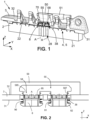
- FIG. 1 illustrates a friction assembly 1 for a brake system for railway rolling stock.
- these brakes are disc brakes.
- these brakes are brakes on a tread of the wheel of the rolling stock.
- the assembly extends longitudinally along a longitudinal axis X, and vertically along a vertical axis Z.
- the transverse axis Y forms a trigonometric reference frame with the axes X and Z.
- the friction assembly 1 is shown in perspective. For the sake of clarity, the assembly is shown in section in the vertical plane (X, Z), that is to say in the plane which passes through the central axes A of the secondary ducts 38.
- the friction assembly 1 comprises on the one hand a sole holder 3, and on the other hand at least one sole 2 made of friction material.
- the sole holder 3 has a lower face 31, and an upper face 32.
- the sole 2 has a first face 21 which is the friction face, and a second face 22.
- the sole 2 is secured to the sole holder 3 by a fixing mechanism (4, 5).
- this fixing mechanism comprises a reception slide 5 which is formed on the lower face 31, and a profile 4 which is formed on the second face 22 and which is configured to cooperate with the reception slide 5.
- the sole 2 is secured to the sole holder 3 by inserting and translating the profile 4 into the slide 5 along the longitudinal axis X.
- the fixing mechanism is then such that this connection is removable.
- the sole 2 is secured to the sole holder 3, which allows the sole 2 to be replaced once worn.
- the sole 2 comprises at least one primary conduit 28 sealingly connecting the first face 21 and the second face 22.
- the sole 2 comprises two primary conduits 28.
- the sole holder 3 comprises at least one secondary conduit 38 with central axis A which sealably connects the upper face 32 and the lower face 31 at the bottom of the receiving slide 5.
- the sole plate holder 3 comprises two secondary conduits 38.
- the sole plate holder 3 comprises at least one junction ring 8 arranged in the at least one secondary conduit 38 and establishing a junction with the at least one primary conduit 28.
- the sole plate holder 3 comprises two connecting rings 8.
- each primary conduit 28 is aligned with a secondary conduit 38, that is to say that the central axis of each primary conduit 28 is the central axis A of the secondary conduit 38 with which it is aligned.
- a connecting ring 8 comprises a tubular body 81 and a collar 82 at one end of this body 81.
- the collar 82 extends radially outwards from the body 81, and therefore has a diameter greater than the external diameter of the body 81.
- the internal diameter of the body 81 is greater than the diameter of a primary conduit 28 in order to compensate for the clearances between the sole 2 and the sole holder 3 along the X axis.
- the distal end of the body 81 is therefore located opposite the collar 82.
- the friction assembly 1 further comprises a block 50 which is an integral part of the sole plate holder 3 at the upper face 32.
- this block 50 is a pneumatic block.
- the block 50 is molded with the sole plate holder 3, or is welded with the sole plate holder 3.
- the block 50 covers the upper face 32 of the sole plate holder 3 at the portion of the upper face 32 which comprises the orifices of the secondary conduits 38.
- the block 50 comprises a cavity 55 which is connected to a circuit 51 which is connected to a suction device.
- Each ring 8 can be inserted into a secondary conduit 38 only via the lower face 31, before securing the sole 2 with the sole holder 3.
- the body 81 of a ring 8 is inserted into a secondary conduit 38, the collar 82 being located on the side of the lower face 31.
- the diameter of the collar 82 is equal to or slightly less than the diameter of the secondary conduit 38.
- the diameter of each of the holes 58 is equal to or slightly greater than the external diameter of the body 81, and less than the diameter of the collar 82.
- a spring for example a helical spring
- the spring is mounted on the body 81 between the collar 82 and the edge of the hole 58. At rest, the spring is in contact with the collar 82 and the edge of the hole 58, and the collar 82 protrudes from the lower face 31 (for example at the bottom of the slide 5 if this slide 5 is present).
- the sole 2 is secured to the sole holder 3 (for example by sliding the profile 4 of the sole 2 in the slide 5) the second face 22 is in contact with the lower face 31, the collar 82 is pushed back into the secondary conduit 38 and compresses the spring.
- This solution is shown in Figure 1 .
- the collar 82 In the case of direct contact between the collar 82 and the edge of the hole 58, the collar 82 is shaped such that, undeformed, it protrudes from the lower face 31.
- the collar 82 When the sole 2 is secured to the sole holder 3, the collar 82 is deformed between the second face 22 and the edge of the hole 58.
- This deformation is for example a compression along the axis A of the material of the collar.
- the collar 82 has a convex or concave shape at rest, and this deformation is a flattening of the collar 82.
- the deformation of the collar 82 also fulfills a sealing function between the ring 8 and the second face 22.
- the collar 82 In both cases of contact (direct or indirect), the collar 82 is held in contact against the second face 22 of the sole 2. This holding is achieved either by deformation of the collar 82 itself, or by compression of the spring, which therefore each constitute a return mechanism 90 which makes it possible to press the collar 82 against the second face 22. Other return mechanisms 90 fulfilling the same function can be used.
- the collar 82 therefore provides a translational blocking of the ring 8 in the secondary conduit 38 along the axis A in one direction, namely the upward direction in the figures (movement of the ring 8 upwards).
- the friction assembly 1 comprises a securing mechanism 70 for securing the connecting rings 8 with the block 50 when each of the connecting rings 8 is arranged in a hole 58 and in a secondary conduit 38.
- a connecting ring 8 is pushed upwards into the hole 58 until its distal end opens into the cavity 55, this securing mechanism 70 prevents the connecting ring 8 from translating in the opposite direction, i.e. downwards.
- the connecting ring 8 is therefore blocked in the position of securing with the block 50 and cannot come out of the hole 58.
- the first step (step (a)) consists of providing the block 50 with a cavity 55, with one or more holes 58 connecting this cavity 55 and the upper face 32 and each located opposite a secondary conduit 38 of the sole plate holder 30 and in which a ring 8 is able to slide, and with a circuit 51 which connects this cavity 55 to the suction device.
- the distal end of the body 81 carries tabs 85 which, at rest, extend radially outwards.
- the tabs 85 are molded.
- the tabs 85 may be machined and shaped by bending.
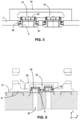
- the figures 2 to 5 And 7 are sectional views in the (X, Z) plane of the region of the friction assembly 1 which includes the block 50.
- the sole 2 is not shown in the figures 2 to 5 And 7 .
- the securing mechanism 70 comprises the collar 82, the tabs 85 and the internal edge of the hole 58 of the cavity 55.
- the term "internal edge” refers to the edge of a hole 58 which is located inside the cavity 55. The operation of the securing mechanism is explained below.
- a joining ring 8 is inserted by sliding along the axis A of this hole 58. This insertion is carried out from the lower face 31 of the sole plate holder, upwards in the figures, and constitutes the second step (step (b)).
- FIG. 2 illustrates the situation where the joining rings 8 are inserted into the secondary conduits 38 and begin to be inserted into the holes 58.
- the distal ends of the tabs 85 are in contact with the external edge of the holes 58.
- the term "external edge” refers to the edge of a hole 58 which is located outside the block 50, i.e. opposite the secondary conduit 38.
- FIG. 3 illustrates the situation where the joining rings 8 are inserted into the holes 58.
- the ends of the tabs 85 are pushed radially towards the longitudinal central axis of the connecting ring 8 by the side wall 585 of the hole 58.
- This deformation of the tabs 85 is within their elastic deformation range.
- the outer edge of each hole 58 is flared towards the outside of the hole 58 so as to help the tabs 85 to be pushed radially towards the central axis of the connecting ring.
- the tabs 85 slide along this side wall 585 from the outer edge to the inner edge of the hole 58.
- FIG. 4 illustrates the situation where the distal end of each joining ring 8 emerges into the cavity 55. Thanks to their elasticity, the tabs 85 then deform radially outwards to return to their initial position (rest position).
- FIG. 5 illustrates the situation where each of the joining rings 8 is lowered until the distal ends of the tabs 85 come into contact with the internal edge of a hole 58. These distal ends being curved radially outwards, they press on the internal edge and prevent the joining rings 8 from coming out of the holes 58 (step (c), third step).
- the tabs 85 and the internal edge of the hole 58 are therefore part of the securing mechanism 70.
- the friction assembly 1 comprises a return mechanism 90 (in the case illustrated in the figures this mechanism is a spring around the connecting ring 8 which is located between the collar 82 and the external edge of the hole 58.
- this spring is helical.
- this return mechanism 90 is activated (the spring is compressed) so that it tends to bring the connecting ring 8 out of the hole 58, that is to say to push the connecting ring 8 downwards, as illustrated in Figure 5
- the collar 82 of each joining ring 8 then emerges partly at the level of the lower face 31 of the sole plate holder 3.
- step (d) the sole 2 is assembled on the sole holder 3 until the sole 2 covers each of the joining rings 8.
- This situation is illustrated in Figure 6 , in the case where the sole consists of two halves.
- the Figure 6 is a sectional view in the (X, Z) plane of a portion of the friction assembly 1 illustrated in Figure 1 .
- the right half of the sole 2 is pressed against the sole holder 3 in such a way that the second face 22 of this right half is in contact with the lower face 31 of the sole holder 3.
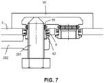
- FIG. 7 illustrates a method for separating a connecting ring 8 from the block 50.
- a threaded rod 201 is screwed into the hole of the connecting ring 8 along its longitudinal axis so that the connecting ring 8 is in helical connection with the rod 201 over its entire length.
- the collar 82 of the connecting ring 8 is gripped with pliers 202 in order to lock it in rotation.
- the connecting ring 8 translates downwards thanks to the thread of the rod 201.
- the tabs 85 are elastically deformed and forced between the rod 201 and the side wall 585 of the hole 58 until they emerge in the secondary conduit 38.
- the connecting ring 8 can then be freely removed from the block 50 and the sole plate holder 3.
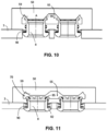
- FIGS. 8 to 12 A second embodiment is now described, illustrated in figures 8 to 12 , in which the distal end of the body 81 carries tabs 85 which extend substantially in the extension of the body 81 in their rest positions and which are capable of being plastically deformed radially outwards.
- figures 8 to 12 are sectional views in the (X, Z) plane of the region of the friction assembly 1 which includes the block 50. For the sake of clarity, the sole 2 is not shown in these figures.
- the securing mechanism 70 comprises the collar 82, the tabs 85 and the internal edge of the hole 58 of the cavity 55. The operation of the securing mechanism is explained below.
- a joining ring 8 is inserted by sliding along the axis A of this hole 58. This insertion is carried out from the lower face 31 of the sole plate holder, upwards in the figures, and constitutes the second step (step (b)).
- FIG. 8 illustrates the situation where the joining rings 8 are inserted into the secondary conduits 38 and before they begin to be inserted into the holes 58.
- FIG. 9 illustrates the situation where the joining rings 8 are inserted into the holes 58.
- the tabs 85 and the body 81 slide freely along the side wall 585 of the hole 58 from the external edge to the internal edge of the hole 58.
- the tabs 85 extend substantially in the extension of the body 81.
- the friction assembly 1 comprises a return mechanism 90 (in the case illustrated in the figures this mechanism is a spring around the connecting ring 8 which is located between the collar 82 and the external edge of the hole 58.
- this spring is helical.
- this return mechanism 90 is activated (the spring is compressed) so that it tends to bring the connecting ring 8 out of the hole 58, that is to say to push the connecting ring 8 downwards, as illustrated in Figure 11
- the collar 82 of each joining ring 8 then emerges partly at the level of the lower face 31 of the sole plate holder 3.
- step (d) the sole 2 is assembled on the sole holder 3 until the sole 2 covers each of the joining rings 8. This situation is similar to that illustrated in Figure 6 in the case of the first embodiment.
- the return mechanism 90 presses the joining ring 8 against the second face 22 of the sole 2, and the distal ends 85 of the joining rings 8 are in the cavity 55.
- the side wall 585 of each hole 58 comprises an O-ring 587 which is housed in an annular cavity of this side wall 585.
- This O-ring 587 makes it possible to improve the sealing between the joining ring 8 and the block 50.
- FIG. 12 illustrates a method for separating a connecting ring 8 from the block 50.
- a threaded rod 201 is screwed into the hole of the connecting ring 8 along its longitudinal axis so that the connecting ring 8 is in helical connection with the rod 201 over its entire length.
- the collar 82 of the connecting ring 8 is gripped with pliers 202 in order to lock it in rotation.
- the connecting ring 8 translates downwards thanks to the thread of the rod 201.
- the tabs 85 are deformed plastically and forced between the rod 201 and the side wall 585 of the hole 58 until they emerge in the secondary conduit 38.
- the joining ring 8 can then be freely removed from the block 50 and the sole plate holder 3.
- each hole 58 carries two diametrically opposed grooves 581 which extend longitudinally along its side wall 585 from the inner edge to the outer edge of the hole 58, such that each of the protrusions 86 is able to slide in one of the grooves 581 when the connecting ring 8 slides in the hole 58.
- the edge of each hole 58 comprises a housing 586 which is able to receive one of the protrusions 86.
- This housing 586 extends radially from the inner edge of the hole 58 and is bordered by a side wall 5861 which extends along the main axis A.
- the housing 586 comprises a bottom 5862 which extends parallel to the floor of the cavity 55.
- the housing 586 is open along the main axis A towards the ceiling of the cavity 55 and is open radially towards the hole 58.
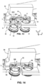
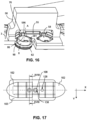
- figures 13 to 16 are perspective and partial sectional views in the plane (X, Z) of the region of the friction assembly 1 which includes the block 50.
- each connecting ring 8 can carry a protuberance 86 or more than two protuberances 86.
- Each hole 58 carries as many grooves 581 as protuberances 86, these grooves 581 being arranged such that each of the protuberances 86 slides in one of the grooves 581 when the connecting ring 8 slides in the hole 58.
- the securing mechanism 70 comprises the collar 82, the protrusion(s) 86 and the housing 586. The operation of the securing mechanism is explained below.
- a joining ring 8 is inserted by sliding along the axis A of this hole 58. This insertion is carried out from the lower face 31 of the sole plate holder, upwards in the figures, and constitutes the second step (step (b)).
- FIG. 13 illustrates the situation where the joining rings 8 are inserted into the secondary conduits 38 and before they begin to be inserted into the holes 58.
- FIG 14 illustrates the situation where the joining rings 8 are inserted into the holes 58.
- the protrusions 86 slide freely in the grooves 581 from the outer edge to the inner edge of the hole 58.
- the friction assembly 1 comprises a return mechanism 90 (in the case illustrated in the figures this mechanism is a spring around the connecting ring 8 which is located between the collar 82 and the external edge of the hole 58.
- this spring is helical.
- this return mechanism 90 is activated (the spring is compressed) so that it tends to bring the connecting ring 8 out of the hole 58.
- the return mechanism 90 pushes the connecting ring 8 downwards and holds the protuberance 86 in the housing 586 so as to secure the connecting ring 8 with the block 50, as illustrated in figure 16
- the collar 82 of each joining ring 8 then emerges partly at the level of the lower face 31 of the sole plate holder 3.
- the at least one connecting ring 8 comprises a body 81 and a collar 82 at a first end of the body 81, the distal end of the body 81 carries tabs 85 which extend substantially in the extension of the body 81 in their rest positions, such that, in step (b), the body 81 slides freely in the at least one hole 58 and in the at least one secondary conduit 38, and, in step (c), the tabs 85 are crushed against the bottom of the cavity such that the tabs are plastically deformed radially outwards and are able to bear against the edge of the at least one hole 58 of the cavity 55.
- the securing mechanism 70 comprises the collar 82, the tabs 85 and said internal edge of the at least one hole 58.
Landscapes
- Engineering & Computer Science (AREA)
- Mechanical Engineering (AREA)
- General Engineering & Computer Science (AREA)
- Transportation (AREA)
- Braking Arrangements (AREA)
- Footwear And Its Accessory, Manufacturing Method And Apparatuses (AREA)
Claims (10)
- Reibungsanordnung (1) für ein Bremssystem für rollendes Eisenbahnmaterial, wobei die Reibungsanordnung (1) aufweist:einerseits einen Belagträger (3), aufweisend eine untere Fläche (31), eine obere Fläche (32) und mindestens eine Sekundärröhre (38) mit zentraler Achse A, die die untere Fläche (31) und eine obere Fläche (32) miteinander verbindet,andererseits mindestens einen Belag (2) aus Reibungsmaterial, aufweisend eine erste Fläche (21), die die Reibungsfläche ist, eine zweite Fläche (22), die geeignet ist, an der unteren Fläche (31) mithilfe eines Befestigungsmechanismus (4, 5) befestigt zu werden, und mindestens eine Primärröhre (28), die die erste Fläche (21) und die zweite Fläche (22) miteinander verbindet, undandererseits mindestens einen Verbindungsring (8), der in der mindestens einen Sekundärröhre (38) angeordnet ist und der eine Verbindung mit der mindestens einen Primärröhre (28) herstellt, wenn die mindestens eine Primärröhre (28) mit der mindestens einen Sekundärröhre (38) ausgerichtet ist,wobei die Reibungsanordnung (1) ferner einen Block (50) aufweist, der an eine Saugvorrichtung angeschlossen ist und integraler Teil des Belagträgers (3) auf der Ebene der oberen Fläche (32) ist,wobei die Reibungsanordnung (1) dadurch gekennzeichnet ist, dass der Block (50) einen Hohlraum (55) aufweist, der über eine Leitung (51) an die Saugvorrichtung angeschlossen ist und der mindestens eine Öffnung (58) aufweist, die den Hohlraum (55) und die obere Fläche (32) verbindet und die mit der mindestens einen Sekundärröhre (38) ausgerichtet ist und in der der Verbindungsring (8) gleiten kann,und dadurch, dass sie aufweist: einen Kopplungsmechanismus (70) zum Koppeln des mindestens einen Verbindungsrings (8) mit dem Block (50), wenn der mindestens eine Verbindungsring (8) in der mindestens einen Öffnung (58) und in der mindestens einen Sekundärröhre (38) angeordnet ist.
- Reibungsanordnung (1) nach Anspruch 1,in welcher der mindestens eine Verbindungsring (8) einen Körper (81) und einen Kragen (82) an einem ersten Ende des Körpers (81) aufweist, wobei das distale Ende des Körpers (81) Zungen (85) trägt, die in dem Hohlraum (55) sich radial nach außen erstrecken, undin welcher der Kopplungsmechanismus (70) den Kragen (82), die Zungen (85) und den Innenrand der mindestens einen Öffnung (58) des Hohlraums (55) aufweist.
- Reibungsanordnung (1) nach Anspruch 1,in welcher der mindestens eine Verbindungsring (8) einen Körper (81) und einen Kragen (82) an einem ersten Ende des Körpers (81) aufweist, wobei das distale Ende des Körpers (81) Zungen (85) trägt, die in dem Hohlraum (55) radial nach außen plastisch verformt sind, undin welcher der Kopplungsmechanismus (70) den Kragen (82), die Zungen (85) und den Innenrand der mindestens einen Öffnung (58) des Hohlraums (55) aufweist.
- Reibungsanordnung (1) nach Anspruch 1,in welcher der mindestens eine Verbindungsring (8) einen Körper (81) und einen Kragen (82) an einem ersten Ende des Körpers (81) aufweist, wobei das distale Ende des Körpers (81) mindestens einen Vorsprung (86) trägt, der sich in dem Hohlraum (55) radial nach außen erstreckt,in welcher die mindestens eine Öffnung (58) mindestens eine Rille (581) trägt, in der der mindestens eine Vorsprung (86) gleiten kann,in welcher der Innenrand der mindestens einen Öffnung (58) des Hohlraums (55) einen Sitz (586) zur Aufnahme des Vorsprungs (86) aufweist, undin welcher der Kopplungsmechanismus (70) den Kragen (82), den Vorsprung (86) und den Sitz (586) aufweist.
- Reibungsanordnung (1) nach einem der Ansprüche 1 bis 4, die ferner einen Rückstellmechanismus (90) aufweist, der fähig ist, den Ring (8) gegen die zweite Fläche (22) zu drücken.
- Reibungsanordnung (1) nach einem der Ansprüche 1 bis 5, in welcher der Befestigungsmechanismus (4, 5) aufweist: eine Aufnahmegleitschiene (5), die an der unteren Fläche (31) gebildet ist, und ein Profil (4), das an der zweiten Fläche (22) gebildet ist und das konfiguriert ist, um mit der Aufnahmegleitschiene (5) zusammenzuwirken.
- Verfahren zum Koppeln mindestens eines an einem Belagträger (3) angeordneten Verbindungsrings (8) mit einem an eine Saugvorrichtung angeschlossenen Block (50), wobei der Belagträger (3) eine untere Fläche (31), eine obere Fläche (32) und mindestens eine Sekundärröhre (38) mit zentraler Achse A aufweist, der Block (50) integraler Teil des Belagträgers (3) auf der Ebene der oberen Fläche (32) ist, der Belagträger (3) und der Verbindungsring (8) Teil einer Reibungsanordnung (1) für ein Bremssystem für rollendes Eisenbahnmaterial sind, wobei die Reibungsanordnung (1) ferner einen Belag (2) aus Reibungsmaterial aufweist, der eine erste Fläche (21), die die Reibungsfläche ist, eine zweite Fläche (22), die geeignet ist, an der unteren Fläche (31) mithilfe eines Befestigungsmechanismus (4, 5) befestigt zu werden, und mindestens eine Primärröhre (28), die die erste Fläche (21) und die zweite Fläche (22) miteinander verbindet, aufweist, wobei der mindestens eine Verbindungsring (8) in der mindestens einen Sekundärröhre (38) angeordnet ist und eine Verbindung mit der mindestens einen Primärröhre (28) herstellt, wenn die mindestens eine Primärröhre (28) mit einer der mindestens einen Sekundärröhre (38) ausgerichtet ist, wobei das Verfahren dadurch gekennzeichnet ist, dass es die folgenden Schritte aufweist:(a) Versehen des Blocks (50) mit einem Hohlraum (55), der via eine Leitung (51) an die Saugvorrichtung angeschlossen ist, mit mindestens einer Öffnung (58), die den Hohlraum (55) und die obere Fläche (32) verbindet und die mit der mindestens einen Sekundärröhre (38) ausgerichtet ist und in der der mindestens eine Verbindungsring (8) gleiten kann;(b) Anordnen des mindestens einen Verbindungsrings (8) in der mindestens einen Öffnung (58) und in der mindestens einen Sekundärröhre (38) durch Einschieben von der unteren Fläche (31) aus entlang der Achse A;(c) Koppeln des mindestens einen Verbindungsrings (8) mit dem Block (50) mithilfe eines Kopplungsmechanismus (70);(d) Anfügen des Belags (2) an den Belagträger (3), bis der Belag (2) den mindestens einen Verbindungsring (8) bedeckt.
- Verfahren nach Anspruch 7,wobei der mindestens eine Verbindungsring (8) einen Körper (81) und einen Kragen (82) an einem ersten Ende des Körpers (81) aufweist, wobei das distale Ende des Körpers (81) Zungen (85) trägt, die sich in ihren Ruhepositionen radial nach außen erstrecken, undwobei im Schritt (b) die Zungen (85) sich auf elastische Weise einander annähern, wenn der Körper (81) in die mindestens eine Öffnung (58) und in die mindestens eine Sekundärröhre (38) geschoben wird, undin welchem im Schritt (c) die Zungen (85) ihre Ruhepositionen wieder einnehmen und fähig sind, sich gegen den Innenrand der mindestens einen Öffnung (58) des Hohlraums (55) zu stützen,wobei der Kopplungsmechanismus (70) den Kragen (82), die Zungen (85) und den Innenrand der mindestens einen Öffnung (58) aufweist.
- Verfahren nach Anspruch 7,wobei der mindestens eine Verbindungsring (8) einen Körper (81) und einen Kragen (82) an einem ersten Ende des Körpers (81) aufweist, wobei das distale Ende des Körpers (81) Zungen (85) trägt, die sich in ihren Ruhepositionen im Wesentlichen in Verlängerung des Körpers (81) erstrecken, undwobei im Schritt (b) der Körper (81) frei in der mindestens einen Öffnung (58) und in der mindestens einen Sekundärröhre (38) gleitet, undwobei im Schritt (c) die Zungen (85) gegen den Boden des Hohlraums gezwungen werden, so dass die Zungen radial nach außen plastisch verformt werden und fähig sind, sich gegen den Innenrand der mindestens einen Öffnung (58) des Hohlraums (55) zu stützen, wobei der Kopplungsmechanismus (70) den Kragen (82), die Zungen (85) und den Innenrand der mindestens einen Öffnung (58) aufweist.
- Verfahren nach Anspruch 7,wobei der mindestens eine Verbindungsring (8) einen Körper (81) und einen Kragen (82) an einem ersten Ende des Körpers (81) aufweist, wobei das distale Ende des Körpers (81) mindestens einen Vorsprung (86) trägt, der sich radial nach außen erstreckt, und die mindestens eine Öffnung (58) mindestens eine Rille (581) trägt, in der der mindestens eine Vorsprung (86) gleiten kann, und der Innenrand der mindestens einen Öffnung (58) einen Sitz (586) aufweist, der geeignet ist, den mindestens einen Vorsprung (86) aufzunehmen,so dass im Schritt (b) der Körper (81) frei in der mindestens einen Öffnung (58) und in der mindestens einen Sekundärröhre (38) gleitet, bis das distale Ende des Körpers (81) in dem Hohlraum (55) auftaucht, undwobei im Schritt (c) der Ring (8) um die Hauptachse A gedreht wird, bis einer des mindestens einen Vorsprungs (86) dem Sitz (586) gegenüberliegt, dann der Ring (8) in Gegenrichtung geschoben wird, bis einer der Vorsprünge (86) in dem Sitz (586) sitzt und sich gegen den Boden des Sitzes (586) stützt, wobei der Kopplungsmechanismus (70) den Kragen (82), den mindestens einen Vorsprung (86) und den Sitz (586) aufweist.
Applications Claiming Priority (2)
| Application Number | Priority Date | Filing Date | Title |
|---|---|---|---|
| FR2107699A FR3125266B1 (fr) | 2021-07-16 | 2021-07-16 | Bague d’étanchéité avec blocage en translation |
| PCT/EP2022/067685 WO2023285129A1 (fr) | 2021-07-16 | 2022-06-28 | Bague d'étanchéité avec blocage en translation |
Publications (2)
| Publication Number | Publication Date |
|---|---|
| EP4370387A1 EP4370387A1 (de) | 2024-05-22 |
| EP4370387B1 true EP4370387B1 (de) | 2025-07-02 |
Family
ID=77411920
Family Applications (1)
| Application Number | Title | Priority Date | Filing Date |
|---|---|---|---|
| EP22737881.7A Active EP4370387B1 (de) | 2021-07-16 | 2022-06-28 | Dichtring mit verriegelung gegen translatorische bewegung |
Country Status (8)
| Country | Link |
|---|---|
| US (1) | US20240336287A1 (de) |
| EP (1) | EP4370387B1 (de) |
| JP (1) | JP2024523740A (de) |
| KR (1) | KR20240035435A (de) |
| CN (1) | CN117651662A (de) |
| CA (1) | CA3223476A1 (de) |
| FR (1) | FR3125266B1 (de) |
| WO (1) | WO2023285129A1 (de) |
Family Cites Families (4)
| Publication number | Priority date | Publication date | Assignee | Title |
|---|---|---|---|---|
| FR3069831B1 (fr) * | 2017-08-01 | 2019-09-13 | Tallano Technologie | Ensemble a friction pour systeme de freinage ferroviaire |
| FR3088394B1 (fr) | 2018-11-08 | 2020-11-20 | Tallano Tech | Systeme de captation de particules de frein a disque ferroviaire avec bague d'etancheite et mecanisme de rappel |
| FR3098178B1 (fr) * | 2019-07-03 | 2021-07-30 | Tallano Tech | Système de sécurisation de pièce montée sur porte-semelle |
| FR3125267B1 (fr) * | 2021-07-16 | 2023-07-28 | Tallano Tech | Ensemble à friction avec bloc connecteur et circuit d’aspiration |
-
2021
- 2021-07-16 FR FR2107699A patent/FR3125266B1/fr active Active
-
2022
- 2022-06-28 CA CA3223476A patent/CA3223476A1/fr active Pending
- 2022-06-28 JP JP2024502149A patent/JP2024523740A/ja active Pending
- 2022-06-28 CN CN202280050209.1A patent/CN117651662A/zh active Pending
- 2022-06-28 US US18/578,147 patent/US20240336287A1/en active Pending
- 2022-06-28 WO PCT/EP2022/067685 patent/WO2023285129A1/fr not_active Ceased
- 2022-06-28 KR KR1020247000258A patent/KR20240035435A/ko active Pending
- 2022-06-28 EP EP22737881.7A patent/EP4370387B1/de active Active
Also Published As
| Publication number | Publication date |
|---|---|
| US20240336287A1 (en) | 2024-10-10 |
| FR3125266A1 (fr) | 2023-01-20 |
| CA3223476A1 (fr) | 2023-01-19 |
| CN117651662A (zh) | 2024-03-05 |
| KR20240035435A (ko) | 2024-03-15 |
| FR3125266B1 (fr) | 2023-06-16 |
| JP2024523740A (ja) | 2024-06-28 |
| WO2023285129A1 (fr) | 2023-01-19 |
| EP4370387A1 (de) | 2024-05-22 |
Similar Documents
| Publication | Publication Date | Title |
|---|---|---|
| EP3877667B1 (de) | System zum sammeln von partikeln von eisenbahnscheibenbremsen | |
| FR3069832B1 (fr) | Ensemble a friction pour systeme de freinage ferroviaire | |
| EP3642091B1 (de) | Bremssystem für schienenfahrzeuge | |
| EP3662171B1 (de) | Scheibenbremsbelag | |
| CA3143067C (fr) | Systeme de securisation de piece montee sur porte-semelle | |
| WO2023285130A1 (fr) | Ensemble à friction avec bloc connecteur et circuit d'aspiration | |
| EP4370387B1 (de) | Dichtring mit verriegelung gegen translatorische bewegung | |
| EP2816251A1 (de) | Bremse für Luftfahrzeugreifen, insbesondere für Hubschrauber | |
| EP4463638A1 (de) | Reibungsanordnung für ein bremssystem für schienenfahrzeuge | |
| CA3116399C (fr) | Systeme de captation de particules de frein a disque ferroviaire | |
| WO2023099839A1 (fr) | Mécanisme de commande pour un système ferroviaire, sytème de ferroviaire pourvu d'un tel mécanisme et véhicule ferroviaire pourvu d'un tel système | |
| FR2912665A1 (fr) | Tiroir de filtre a serrage par cable. | |
| FR2841619A1 (fr) | Frein a tambour a securite amelioree et procede de montage dudit frein a tambour | |
| EP1914437A1 (de) | Scheibenbremse mit rückstellendem Dämpfungsblech | |
| EP4396470A1 (de) | Belagelement für eine auf einem bremsträger befestigte schwimmsattel-scheibenbremse | |
| FR2874068A1 (fr) | Frein a disque pour vehicule automobile | |
| FR2474639A1 (fr) | Raccord de gonflage |
Legal Events
| Date | Code | Title | Description |
|---|---|---|---|
| STAA | Information on the status of an ep patent application or granted ep patent |
Free format text: STATUS: UNKNOWN |
|
| STAA | Information on the status of an ep patent application or granted ep patent |
Free format text: STATUS: THE INTERNATIONAL PUBLICATION HAS BEEN MADE |
|
| PUAI | Public reference made under article 153(3) epc to a published international application that has entered the european phase |
Free format text: ORIGINAL CODE: 0009012 |
|
| STAA | Information on the status of an ep patent application or granted ep patent |
Free format text: STATUS: REQUEST FOR EXAMINATION WAS MADE |
|
| 17P | Request for examination filed |
Effective date: 20231219 |
|
| AK | Designated contracting states |
Kind code of ref document: A1 Designated state(s): AL AT BE BG CH CY CZ DE DK EE ES FI FR GB GR HR HU IE IS IT LI LT LU LV MC MK MT NL NO PL PT RO RS SE SI SK SM TR |
|
| DAV | Request for validation of the european patent (deleted) | ||
| DAX | Request for extension of the european patent (deleted) | ||
| GRAP | Despatch of communication of intention to grant a patent |
Free format text: ORIGINAL CODE: EPIDOSNIGR1 |
|
| STAA | Information on the status of an ep patent application or granted ep patent |
Free format text: STATUS: GRANT OF PATENT IS INTENDED |
|
| INTG | Intention to grant announced |
Effective date: 20250220 |
|
| P01 | Opt-out of the competence of the unified patent court (upc) registered |
Free format text: CASE NUMBER: APP_17757/2025 Effective date: 20250411 |
|
| GRAS | Grant fee paid |
Free format text: ORIGINAL CODE: EPIDOSNIGR3 |
|
| GRAA | (expected) grant |
Free format text: ORIGINAL CODE: 0009210 |
|
| STAA | Information on the status of an ep patent application or granted ep patent |
Free format text: STATUS: THE PATENT HAS BEEN GRANTED |
|
| AK | Designated contracting states |
Kind code of ref document: B1 Designated state(s): AL AT BE BG CH CY CZ DE DK EE ES FI FR GB GR HR HU IE IS IT LI LT LU LV MC MK MT NL NO PL PT RO RS SE SI SK SM TR |
|
| REG | Reference to a national code |
Ref country code: GB Ref legal event code: FG4D Free format text: NOT ENGLISH |
|
| REG | Reference to a national code |
Ref country code: CH Ref legal event code: EP |
|
| REG | Reference to a national code |
Ref country code: DE Ref legal event code: R096 Ref document number: 602022016972 Country of ref document: DE |
|
| REG | Reference to a national code |
Ref country code: IE Ref legal event code: FG4D Free format text: LANGUAGE OF EP DOCUMENT: FRENCH |
|
| REG | Reference to a national code |
Ref country code: NL Ref legal event code: MP Effective date: 20250702 |
|
| PG25 | Lapsed in a contracting state [announced via postgrant information from national office to epo] |
Ref country code: PT Free format text: LAPSE BECAUSE OF FAILURE TO SUBMIT A TRANSLATION OF THE DESCRIPTION OR TO PAY THE FEE WITHIN THE PRESCRIBED TIME-LIMIT Effective date: 20251103 |
|
| PG25 | Lapsed in a contracting state [announced via postgrant information from national office to epo] |
Ref country code: NL Free format text: LAPSE BECAUSE OF FAILURE TO SUBMIT A TRANSLATION OF THE DESCRIPTION OR TO PAY THE FEE WITHIN THE PRESCRIBED TIME-LIMIT Effective date: 20250702 |
|
| REG | Reference to a national code |
Ref country code: AT Ref legal event code: MK05 Ref document number: 1808914 Country of ref document: AT Kind code of ref document: T Effective date: 20250702 |
|
| PG25 | Lapsed in a contracting state [announced via postgrant information from national office to epo] |
Ref country code: IS Free format text: LAPSE BECAUSE OF FAILURE TO SUBMIT A TRANSLATION OF THE DESCRIPTION OR TO PAY THE FEE WITHIN THE PRESCRIBED TIME-LIMIT Effective date: 20251102 |
|
| PG25 | Lapsed in a contracting state [announced via postgrant information from national office to epo] |
Ref country code: NO Free format text: LAPSE BECAUSE OF FAILURE TO SUBMIT A TRANSLATION OF THE DESCRIPTION OR TO PAY THE FEE WITHIN THE PRESCRIBED TIME-LIMIT Effective date: 20251002 |
|
| REG | Reference to a national code |
Ref country code: LT Ref legal event code: MG9D |
|
| PG25 | Lapsed in a contracting state [announced via postgrant information from national office to epo] |
Ref country code: AT Free format text: LAPSE BECAUSE OF FAILURE TO SUBMIT A TRANSLATION OF THE DESCRIPTION OR TO PAY THE FEE WITHIN THE PRESCRIBED TIME-LIMIT Effective date: 20250702 |
|
| PG25 | Lapsed in a contracting state [announced via postgrant information from national office to epo] |
Ref country code: FI Free format text: LAPSE BECAUSE OF FAILURE TO SUBMIT A TRANSLATION OF THE DESCRIPTION OR TO PAY THE FEE WITHIN THE PRESCRIBED TIME-LIMIT Effective date: 20250702 |
|
| PG25 | Lapsed in a contracting state [announced via postgrant information from national office to epo] |
Ref country code: HR Free format text: LAPSE BECAUSE OF FAILURE TO SUBMIT A TRANSLATION OF THE DESCRIPTION OR TO PAY THE FEE WITHIN THE PRESCRIBED TIME-LIMIT Effective date: 20250702 |
|
| PG25 | Lapsed in a contracting state [announced via postgrant information from national office to epo] |
Ref country code: GR Free format text: LAPSE BECAUSE OF FAILURE TO SUBMIT A TRANSLATION OF THE DESCRIPTION OR TO PAY THE FEE WITHIN THE PRESCRIBED TIME-LIMIT Effective date: 20251003 |
|
| PG25 | Lapsed in a contracting state [announced via postgrant information from national office to epo] |
Ref country code: CZ Free format text: LAPSE BECAUSE OF FAILURE TO SUBMIT A TRANSLATION OF THE DESCRIPTION OR TO PAY THE FEE WITHIN THE PRESCRIBED TIME-LIMIT Effective date: 20250702 Ref country code: SE Free format text: LAPSE BECAUSE OF FAILURE TO SUBMIT A TRANSLATION OF THE DESCRIPTION OR TO PAY THE FEE WITHIN THE PRESCRIBED TIME-LIMIT Effective date: 20250702 |
|
| PG25 | Lapsed in a contracting state [announced via postgrant information from national office to epo] |
Ref country code: LV Free format text: LAPSE BECAUSE OF FAILURE TO SUBMIT A TRANSLATION OF THE DESCRIPTION OR TO PAY THE FEE WITHIN THE PRESCRIBED TIME-LIMIT Effective date: 20250702 |
|
| PG25 | Lapsed in a contracting state [announced via postgrant information from national office to epo] |
Ref country code: PL Free format text: LAPSE BECAUSE OF FAILURE TO SUBMIT A TRANSLATION OF THE DESCRIPTION OR TO PAY THE FEE WITHIN THE PRESCRIBED TIME-LIMIT Effective date: 20250702 Ref country code: BG Free format text: LAPSE BECAUSE OF FAILURE TO SUBMIT A TRANSLATION OF THE DESCRIPTION OR TO PAY THE FEE WITHIN THE PRESCRIBED TIME-LIMIT Effective date: 20250702 |
|
| PG25 | Lapsed in a contracting state [announced via postgrant information from national office to epo] |
Ref country code: RS Free format text: LAPSE BECAUSE OF FAILURE TO SUBMIT A TRANSLATION OF THE DESCRIPTION OR TO PAY THE FEE WITHIN THE PRESCRIBED TIME-LIMIT Effective date: 20251002 |
|
| PG25 | Lapsed in a contracting state [announced via postgrant information from national office to epo] |
Ref country code: ES Free format text: LAPSE BECAUSE OF FAILURE TO SUBMIT A TRANSLATION OF THE DESCRIPTION OR TO PAY THE FEE WITHIN THE PRESCRIBED TIME-LIMIT Effective date: 20250702 |
|
| PG25 | Lapsed in a contracting state [announced via postgrant information from national office to epo] |
Ref country code: SM Free format text: LAPSE BECAUSE OF FAILURE TO SUBMIT A TRANSLATION OF THE DESCRIPTION OR TO PAY THE FEE WITHIN THE PRESCRIBED TIME-LIMIT Effective date: 20250702 |
|
| PG25 | Lapsed in a contracting state [announced via postgrant information from national office to epo] |
Ref country code: DK Free format text: LAPSE BECAUSE OF FAILURE TO SUBMIT A TRANSLATION OF THE DESCRIPTION OR TO PAY THE FEE WITHIN THE PRESCRIBED TIME-LIMIT Effective date: 20250702 |