EP3875868B1 - Schutzvorrichtung für rohrförmigen dickschichtheizer und rohrförmiger dickschichtheizer - Google Patents
Schutzvorrichtung für rohrförmigen dickschichtheizer und rohrförmiger dickschichtheizer Download PDFInfo
- Publication number
- EP3875868B1 EP3875868B1 EP18938483.7A EP18938483A EP3875868B1 EP 3875868 B1 EP3875868 B1 EP 3875868B1 EP 18938483 A EP18938483 A EP 18938483A EP 3875868 B1 EP3875868 B1 EP 3875868B1
- Authority
- EP
- European Patent Office
- Prior art keywords
- tube
- tubular
- outer tube
- heater assembly
- thick film
- Prior art date
- Legal status (The legal status is an assumption and is not a legal conclusion. Google has not performed a legal analysis and makes no representation as to the accuracy of the status listed.)
- Active
Links
Images


Classifications
-
- F—MECHANICAL ENGINEERING; LIGHTING; HEATING; WEAPONS; BLASTING
- F24—HEATING; RANGES; VENTILATING
- F24H—FLUID HEATERS, e.g. WATER OR AIR HEATERS, HAVING HEAT-GENERATING MEANS, e.g. HEAT PUMPS, IN GENERAL
- F24H1/00—Water heaters, e.g. boilers, continuous-flow heaters or water-storage heaters
- F24H1/10—Continuous-flow heaters, i.e. heaters in which heat is generated only while the water is flowing, e.g. with direct contact of the water with the heating medium
- F24H1/12—Continuous-flow heaters, i.e. heaters in which heat is generated only while the water is flowing, e.g. with direct contact of the water with the heating medium in which the water is kept separate from the heating medium
- F24H1/14—Continuous-flow heaters, i.e. heaters in which heat is generated only while the water is flowing, e.g. with direct contact of the water with the heating medium in which the water is kept separate from the heating medium by tubes, e.g. bent in serpentine form
- F24H1/142—Continuous-flow heaters, i.e. heaters in which heat is generated only while the water is flowing, e.g. with direct contact of the water with the heating medium in which the water is kept separate from the heating medium by tubes, e.g. bent in serpentine form using electric energy supply
-
- F—MECHANICAL ENGINEERING; LIGHTING; HEATING; WEAPONS; BLASTING
- F28—HEAT EXCHANGE IN GENERAL
- F28D—HEAT-EXCHANGE APPARATUS, NOT PROVIDED FOR IN ANOTHER SUBCLASS, IN WHICH THE HEAT-EXCHANGE MEDIA DO NOT COME INTO DIRECT CONTACT
- F28D1/00—Heat-exchange apparatus having stationary conduit assemblies for one heat-exchange medium only, the media being in contact with different sides of the conduit wall, in which the other heat-exchange medium is a large body of fluid, e.g. domestic or motor car radiators
- F28D1/06—Heat-exchange apparatus having stationary conduit assemblies for one heat-exchange medium only, the media being in contact with different sides of the conduit wall, in which the other heat-exchange medium is a large body of fluid, e.g. domestic or motor car radiators with the heat-exchange conduits forming part of, or being attached to, the tank containing the body of fluid
-
- F—MECHANICAL ENGINEERING; LIGHTING; HEATING; WEAPONS; BLASTING
- F24—HEATING; RANGES; VENTILATING
- F24H—FLUID HEATERS, e.g. WATER OR AIR HEATERS, HAVING HEAT-GENERATING MEANS, e.g. HEAT PUMPS, IN GENERAL
- F24H1/00—Water heaters, e.g. boilers, continuous-flow heaters or water-storage heaters
- F24H1/10—Continuous-flow heaters, i.e. heaters in which heat is generated only while the water is flowing, e.g. with direct contact of the water with the heating medium
- F24H1/12—Continuous-flow heaters, i.e. heaters in which heat is generated only while the water is flowing, e.g. with direct contact of the water with the heating medium in which the water is kept separate from the heating medium
- F24H1/121—Continuous-flow heaters, i.e. heaters in which heat is generated only while the water is flowing, e.g. with direct contact of the water with the heating medium in which the water is kept separate from the heating medium using electric energy supply
-
- F—MECHANICAL ENGINEERING; LIGHTING; HEATING; WEAPONS; BLASTING
- F24—HEATING; RANGES; VENTILATING
- F24H—FLUID HEATERS, e.g. WATER OR AIR HEATERS, HAVING HEAT-GENERATING MEANS, e.g. HEAT PUMPS, IN GENERAL
- F24H15/00—Control of fluid heaters
- F24H15/10—Control of fluid heaters characterised by the purpose of the control
- F24H15/128—Preventing overheating
-
- F—MECHANICAL ENGINEERING; LIGHTING; HEATING; WEAPONS; BLASTING
- F24—HEATING; RANGES; VENTILATING
- F24H—FLUID HEATERS, e.g. WATER OR AIR HEATERS, HAVING HEAT-GENERATING MEANS, e.g. HEAT PUMPS, IN GENERAL
- F24H15/00—Control of fluid heaters
- F24H15/10—Control of fluid heaters characterised by the purpose of the control
- F24H15/14—Cleaning; Sterilising; Preventing contamination by bacteria or microorganisms, e.g. by replacing fluid in tanks or conduits
-
- F—MECHANICAL ENGINEERING; LIGHTING; HEATING; WEAPONS; BLASTING
- F24—HEATING; RANGES; VENTILATING
- F24H—FLUID HEATERS, e.g. WATER OR AIR HEATERS, HAVING HEAT-GENERATING MEANS, e.g. HEAT PUMPS, IN GENERAL
- F24H15/00—Control of fluid heaters
- F24H15/20—Control of fluid heaters characterised by control inputs
- F24H15/212—Temperature of the water
- F24H15/219—Temperature of the water after heating
-
- F—MECHANICAL ENGINEERING; LIGHTING; HEATING; WEAPONS; BLASTING
- F24—HEATING; RANGES; VENTILATING
- F24H—FLUID HEATERS, e.g. WATER OR AIR HEATERS, HAVING HEAT-GENERATING MEANS, e.g. HEAT PUMPS, IN GENERAL
- F24H15/00—Control of fluid heaters
- F24H15/30—Control of fluid heaters characterised by control outputs; characterised by the components to be controlled
- F24H15/335—Control of pumps, e.g. on-off control
- F24H15/34—Control of the speed of pumps
-
- F—MECHANICAL ENGINEERING; LIGHTING; HEATING; WEAPONS; BLASTING
- F24—HEATING; RANGES; VENTILATING
- F24H—FLUID HEATERS, e.g. WATER OR AIR HEATERS, HAVING HEAT-GENERATING MEANS, e.g. HEAT PUMPS, IN GENERAL
- F24H15/00—Control of fluid heaters
- F24H15/30—Control of fluid heaters characterised by control outputs; characterised by the components to be controlled
- F24H15/355—Control of heat-generating means in heaters
- F24H15/37—Control of heat-generating means in heaters of electric heaters
-
- F—MECHANICAL ENGINEERING; LIGHTING; HEATING; WEAPONS; BLASTING
- F24—HEATING; RANGES; VENTILATING
- F24H—FLUID HEATERS, e.g. WATER OR AIR HEATERS, HAVING HEAT-GENERATING MEANS, e.g. HEAT PUMPS, IN GENERAL
- F24H9/00—Details
- F24H9/0005—Details for water heaters
- F24H9/001—Guiding means
- F24H9/0015—Guiding means in water channels
-
- F—MECHANICAL ENGINEERING; LIGHTING; HEATING; WEAPONS; BLASTING
- F24—HEATING; RANGES; VENTILATING
- F24H—FLUID HEATERS, e.g. WATER OR AIR HEATERS, HAVING HEAT-GENERATING MEANS, e.g. HEAT PUMPS, IN GENERAL
- F24H9/00—Details
- F24H9/02—Casings; Cover lids; Ornamental panels
-
- F—MECHANICAL ENGINEERING; LIGHTING; HEATING; WEAPONS; BLASTING
- F24—HEATING; RANGES; VENTILATING
- F24H—FLUID HEATERS, e.g. WATER OR AIR HEATERS, HAVING HEAT-GENERATING MEANS, e.g. HEAT PUMPS, IN GENERAL
- F24H9/00—Details
- F24H9/18—Arrangement or mounting of grates or heating means
-
- F—MECHANICAL ENGINEERING; LIGHTING; HEATING; WEAPONS; BLASTING
- F24—HEATING; RANGES; VENTILATING
- F24H—FLUID HEATERS, e.g. WATER OR AIR HEATERS, HAVING HEAT-GENERATING MEANS, e.g. HEAT PUMPS, IN GENERAL
- F24H9/00—Details
- F24H9/18—Arrangement or mounting of grates or heating means
- F24H9/1809—Arrangement or mounting of grates or heating means for water heaters
- F24H9/1818—Arrangement or mounting of electric heating means
-
- F—MECHANICAL ENGINEERING; LIGHTING; HEATING; WEAPONS; BLASTING
- F24—HEATING; RANGES; VENTILATING
- F24H—FLUID HEATERS, e.g. WATER OR AIR HEATERS, HAVING HEAT-GENERATING MEANS, e.g. HEAT PUMPS, IN GENERAL
- F24H9/00—Details
- F24H9/20—Arrangement or mounting of control or safety devices
- F24H9/2007—Arrangement or mounting of control or safety devices for water heaters
- F24H9/2014—Arrangement or mounting of control or safety devices for water heaters using electrical energy supply
- F24H9/2028—Continuous-flow heaters
-
- F—MECHANICAL ENGINEERING; LIGHTING; HEATING; WEAPONS; BLASTING
- F28—HEAT EXCHANGE IN GENERAL
- F28F—DETAILS OF HEAT-EXCHANGE AND HEAT-TRANSFER APPARATUS, OF GENERAL APPLICATION
- F28F1/00—Tubular elements; Assemblies of tubular elements
- F28F1/10—Tubular elements and assemblies thereof with means for increasing heat-transfer area, e.g. with fins, with projections, with recesses
- F28F1/40—Tubular elements and assemblies thereof with means for increasing heat-transfer area, e.g. with fins, with projections, with recesses the means being only inside the tubular element
- F28F1/405—Tubular elements and assemblies thereof with means for increasing heat-transfer area, e.g. with fins, with projections, with recesses the means being only inside the tubular element and being formed of wires
-
- H—ELECTRICITY
- H05—ELECTRIC TECHNIQUES NOT OTHERWISE PROVIDED FOR
- H05B—ELECTRIC HEATING; ELECTRIC LIGHT SOURCES NOT OTHERWISE PROVIDED FOR; CIRCUIT ARRANGEMENTS FOR ELECTRIC LIGHT SOURCES, IN GENERAL
- H05B3/00—Ohmic-resistance heating
- H05B3/02—Details
-
- H—ELECTRICITY
- H05—ELECTRIC TECHNIQUES NOT OTHERWISE PROVIDED FOR
- H05B—ELECTRIC HEATING; ELECTRIC LIGHT SOURCES NOT OTHERWISE PROVIDED FOR; CIRCUIT ARRANGEMENTS FOR ELECTRIC LIGHT SOURCES, IN GENERAL
- H05B3/00—Ohmic-resistance heating
- H05B3/40—Heating elements having the shape of rods or tubes
- H05B3/42—Heating elements having the shape of rods or tubes non-flexible
- H05B3/44—Heating elements having the shape of rods or tubes non-flexible heating conductor arranged within rods or tubes of insulating material
-
- F—MECHANICAL ENGINEERING; LIGHTING; HEATING; WEAPONS; BLASTING
- F24—HEATING; RANGES; VENTILATING
- F24H—FLUID HEATERS, e.g. WATER OR AIR HEATERS, HAVING HEAT-GENERATING MEANS, e.g. HEAT PUMPS, IN GENERAL
- F24H15/00—Control of fluid heaters
- F24H15/20—Control of fluid heaters characterised by control inputs
- F24H15/281—Input from user
-
- F—MECHANICAL ENGINEERING; LIGHTING; HEATING; WEAPONS; BLASTING
- F24—HEATING; RANGES; VENTILATING
- F24H—FLUID HEATERS, e.g. WATER OR AIR HEATERS, HAVING HEAT-GENERATING MEANS, e.g. HEAT PUMPS, IN GENERAL
- F24H15/00—Control of fluid heaters
- F24H15/20—Control of fluid heaters characterised by control inputs
- F24H15/288—Accumulation of deposits, e.g. lime or scale
-
- F—MECHANICAL ENGINEERING; LIGHTING; HEATING; WEAPONS; BLASTING
- F24—HEATING; RANGES; VENTILATING
- F24H—FLUID HEATERS, e.g. WATER OR AIR HEATERS, HAVING HEAT-GENERATING MEANS, e.g. HEAT PUMPS, IN GENERAL
- F24H15/00—Control of fluid heaters
- F24H15/30—Control of fluid heaters characterised by control outputs; characterised by the components to be controlled
- F24H15/395—Information to users, e.g. alarms
-
- F—MECHANICAL ENGINEERING; LIGHTING; HEATING; WEAPONS; BLASTING
- F28—HEAT EXCHANGE IN GENERAL
- F28D—HEAT-EXCHANGE APPARATUS, NOT PROVIDED FOR IN ANOTHER SUBCLASS, IN WHICH THE HEAT-EXCHANGE MEDIA DO NOT COME INTO DIRECT CONTACT
- F28D21/00—Heat-exchange apparatus not covered by any of the groups F28D1/00 - F28D20/00
- F28D2021/0019—Other heat exchangers for particular applications; Heat exchange systems not otherwise provided for
- F28D2021/0024—Other heat exchangers for particular applications; Heat exchange systems not otherwise provided for for combustion apparatus, e.g. for boilers
-
- F—MECHANICAL ENGINEERING; LIGHTING; HEATING; WEAPONS; BLASTING
- F28—HEAT EXCHANGE IN GENERAL
- F28F—DETAILS OF HEAT-EXCHANGE AND HEAT-TRANSFER APPARATUS, OF GENERAL APPLICATION
- F28F2275/00—Fastening; Joining
- F28F2275/06—Fastening; Joining by welding
-
- H—ELECTRICITY
- H05—ELECTRIC TECHNIQUES NOT OTHERWISE PROVIDED FOR
- H05B—ELECTRIC HEATING; ELECTRIC LIGHT SOURCES NOT OTHERWISE PROVIDED FOR; CIRCUIT ARRANGEMENTS FOR ELECTRIC LIGHT SOURCES, IN GENERAL
- H05B2203/00—Aspects relating to Ohmic resistive heating covered by group H05B3/00
- H05B2203/002—Heaters using a particular layout for the resistive material or resistive elements
- H05B2203/007—Heaters using a particular layout for the resistive material or resistive elements using multiple electrically connected resistive elements or resistive zones
-
- H—ELECTRICITY
- H05—ELECTRIC TECHNIQUES NOT OTHERWISE PROVIDED FOR
- H05B—ELECTRIC HEATING; ELECTRIC LIGHT SOURCES NOT OTHERWISE PROVIDED FOR; CIRCUIT ARRANGEMENTS FOR ELECTRIC LIGHT SOURCES, IN GENERAL
- H05B2203/00—Aspects relating to Ohmic resistive heating covered by group H05B3/00
- H05B2203/013—Heaters using resistive films or coatings
-
- H—ELECTRICITY
- H05—ELECTRIC TECHNIQUES NOT OTHERWISE PROVIDED FOR
- H05B—ELECTRIC HEATING; ELECTRIC LIGHT SOURCES NOT OTHERWISE PROVIDED FOR; CIRCUIT ARRANGEMENTS FOR ELECTRIC LIGHT SOURCES, IN GENERAL
- H05B2203/00—Aspects relating to Ohmic resistive heating covered by group H05B3/00
- H05B2203/016—Heaters using particular connecting means
-
- H—ELECTRICITY
- H05—ELECTRIC TECHNIQUES NOT OTHERWISE PROVIDED FOR
- H05B—ELECTRIC HEATING; ELECTRIC LIGHT SOURCES NOT OTHERWISE PROVIDED FOR; CIRCUIT ARRANGEMENTS FOR ELECTRIC LIGHT SOURCES, IN GENERAL
- H05B2203/00—Aspects relating to Ohmic resistive heating covered by group H05B3/00
- H05B2203/021—Heaters specially adapted for heating liquids
Definitions
- the present invention relates to the field of liquid heater technologies, and in particular, to a protection apparatus for protecting a tubular thick film heater, and a tubular thick film heater with a protection function.
- a tubular thick film heater needs to be electrically connected to and controlled by an external circuit.
- the heater When the heater operates, a surface of a heating resistor is energized, and an operating temperature is high. Therefore, safety protection and heat insulation from the external circuit are needed.
- US2010/046934A1 discloses a tubular thick film heater without a protection apparatus.
- CN106595030A discloses a tubular thick film heater with a protection apparatus according to the preamble of present claim 1.
- an existing tubular thick film heater is protected only by a protective housing mounted outside a tubular heater assembly, and cannot properly implement electrical and heat isolation between the tubular thick film heater and an external circuit during operation. Therefore, the existing tubular thick film heater causes certain danger.
- the present invention aims to provide a tubular thick film heater protection apparatus to protect a tubular heater assembly, thereby solving a problem that an existing tubular thick film heater does not properly provide insulation protection during operation.
- a tubular thick film heater protection apparatus provided in the embodiments of the present invention is implemented by using the following technical solutions:
- a tubular thick film heater protection apparatus is configured to protect a tubular heater assembly and includes:
- the tubular thick film heater protection apparatus further includes a first annular groove sealing ring disposed in the upper groove and a second annular groove sealing ring disposed in the lower groove, where a groove width of the first annular groove sealing ring matches the width of the upper portion of the tubular heater assembly, and a groove width of the second annular groove sealing ring matches the width of the lower portion of the tubular heater assembly.
- the upper tube is a cylinder
- the base is a cylindrical base
- the tubular thick film heater protection apparatus further includes an annular sealing ring disposed on the cylindrical base, and the annular sealing ring is disposed in a junction portion between the cylinder and the cylindrical base.
- the base is provided with a first positioning apparatus, and the first positioning apparatus is configured to determine a matching position between the tubular heater assembly and the base, so that the terminal contact of the elastic contact piece can be connected to the electrode on the outer tube of the tubular heater assembly through contact; and a second positioning apparatus is disposed on the downward inner ring flange of the toroid, and the second positioning apparatus is configured to determine a matching position between the tubular heater assembly and the upper tube to implement position matching between the first locking mechanism and the second locking mechanism.
- the first locking mechanism includes a clip with a bayonet, which is disposed on a lower portion of an inner side surface of the upper tube;
- the second locking mechanism includes an elastic component clamp with a protrusion, and a locking function can be implemented by matching the protrusion of the clamp with the bayonet of the clip; or: the second locking mechanism includes a clip with a bayonet, the first locking mechanism includes an elastic component clamp with a protrusion, and a locking function can be implemented by matching the protrusion of the clamp with the bayonet of the clip; and a mounting and fastening apparatus is disposed on an outer side wall of the upper tube.
- An embodiment of the present invention further provides a tubular thick film heater, including:
- both the inner circular wall and the outer tube are stainless steel tubes.
- the spiral flow guide structure is formed by a spiral metal wire sleeved on the inner tube; the spiral metal wire is a stainless steel wire, and the stainless steel wire is welded to the outer peripheral wall of the inner tube; and/or an axial cross-sectional shape of the spiral metal wire is a triangle, a trapezoid, or a rectangle, and/or two ends of the inner tube are respectively flush with two ends of the outer tube.
- the heating assembly includes an insulation medium layer configured on the outer peripheral wall of the outer tube and a heating circuit configured at the insulation medium layer, the heating circuit includes multiple heating resistors and electrodes that are fastened to the insulation medium layer, and two ends of the heating resistor are electrically connected to the electrodes, respectively; an extension direction of each of the heating resistors is the same as the length direction of the outer tube; the liquid inlet is connected to a water pump; and the tubular thick film heater further includes a first temperature sensor and a first controller electrically connected to the first temperature sensor; where the first temperature sensor is configured at a position on the outer tube that is close to the liquid outlet, and the first controller is configured to control a liquid intake speed of the water pump and/or heating power of the heating resistors based on temperature information sent by the first temperature sensor.
- the multiple heating resistors are distributed around the outer peripheral wall of the outer tube; and the tubular thick film heater further includes a second temperature sensor and a second controller electrically connected to the second temperature sensor; where the second temperature sensor is disposed on the outer tube and close to the heating resistors, and is configured to detect an outer tube temperature at a position of the second temperature sensor; and the second controller is configured to receive the outer tube temperature sent by the second temperature sensor, and when the outer tube temperature is higher than a first preset temperature threshold in a first preset heating time period, control the heating circuit to be disconnected and/or send no-liquid burning warning information.
- This present invention further provides a tubular thick film heater with a protection function, including the tubular thick film heater protection apparatus described above, and further including a tubular heater assembly;
- the spiral flow guide structure is formed by a spiral metal wire sleeved on the inner tube; the spiral metal wire is a stainless steel wire, and the stainless steel wire is welded to the outer peripheral wall of the inner tube; and/or an axial cross-sectional shape of the spiral metal wire is a triangle, a trapezoid, or a rectangle, and/or two ends of the inner tube are respectively flush with two ends of the outer tube.
- the heating assembly includes an insulation medium layer configured on the outer peripheral wall of the outer tube and a heating circuit configured at the insulation medium layer, the heating circuit includes multiple heating resistors and electrodes that are fastened to the insulation medium layer, and two ends of the heating resistor are electrically connected to the electrodes, respectively; an extension direction of each of the heating resistors is the same as the length direction of the outer tube; the liquid inlet is connected to a water pump; and the heater assembly further includes a first temperature sensor and a first controller electrically connected to the first temperature sensor; where the first temperature sensor is configured at a position on the outer tube that is close to the liquid outlet, and the first controller is configured to control a liquid intake speed of the water pump and/or heating power of the heating resistors based on temperature information sent by the first temperature sensor.
- the multiple heating resistors are distributed around the outer peripheral wall of the outer tube; and the heater assembly further includes a second temperature sensor and a second controller electrically connected to the second temperature sensor; where the second temperature sensor is disposed on the outer tube and close to the heating resistors, and is configured to detect an outer tube temperature at a position of the second temperature sensor; and the second controller is configured to receive the outer tube temperature sent by the second temperature sensor, and when the outer tube temperature is higher than a first preset temperature threshold in a first preset heating time period or is higher than a second preset temperature threshold during operation, control the heating circuit to be disconnected and/or send over-temperature protection warning information.
- the heating resistors directly face the spiral flow guide structure through a stainless steel tube, and an inner wall of the outer tube directly facing the heating resistors is inside the liquid flow channel.
- a sealing end cover is used to seal and connect to an end portion of the flow channel formed by the inner tube and the outer tube. Specifically, after the sealing end cover is snapped to the end portion of the flow channel formed by the inner tube and the outer tube, a first turnup edge and a second turnup edge on the sealing end cover are welded to the inner tube and the outer tube.
- Such a manner of separately processing the sealing and connecting structure facilitates manufacturing and avoids a complex process for turnup edges on the inner tube and the outer tube. It is easy to implement batch production, reduces manufacturing costs, and features a good sealing effect and improves stability performance of a heating apparatus in a high-temperature and high-pressure environment for a long term.
- 10 tubular heater assembly
- 1 inner tube
- 11 spiral flow guide structure
- 12 liquid inlet
- 121 liquid intake conduit
- 13 liquid outlet
- 131 liquid discharge conduit
- 14 flow channel
- 20 heating assembly
- 21 outer tube
- 211 insulation medium layer
- 22 heating circuit
- 221 heating resistor
- 222 electrode
- 223 first temperature sensor
- 224 second temperature sensor
- 3 annular sealing end cover
- 31 inner circular wall
- 32 outer circular wall
- 33 upper sealing surface
- 34 lower sealing surface
- 40 upper tube
- 41 upper tube side surface
- 42 toroid
- 43 inner ring surface
- 44 mounting and fastening apparatus
- 45 flange
- 46 first locking mechanism
- 47 upper groove
- 48 second positioning apparatus
- 51 first annular groove sealing ring
- 52 second annular groove sealing ring
- 53 annular sealing ring
- 60 base
- 61 second locking mechanism
- 62 elastic contact piece
- 63 lower groove
- 64 first positioning apparatus
- 65 wiring terminal
- 70 sealed
- connection may be a fixed connection, a detachable connection, or an integrated connection; may be a mechanical connection or an electrical connection; and may be a direct connection, a connection through an intermediate medium, or a connection inside two elements.
- connection may be a fixed connection, a detachable connection, or an integrated connection; may be a mechanical connection or an electrical connection; and may be a direct connection, a connection through an intermediate medium, or a connection inside two elements.
- an embodiment of the present invention provides a tubular thick film heater with a protection function, including a tubular thick film heater protection apparatus and a tubular heater assembly 10.
- An upper portion of the tubular heater assembly 10 is sleeved inside an upper groove 47 of an upper tube 40, and a lower portion of the tubular heater assembly 10 is sleeved inside a lower groove 63 of a base 60. Further, the upper portion of the tubular heater assembly 10 is first sleeved inside a groove of a first annular groove sealing ring 51, and then the first annular groove sealing ring 51 is sleeved inside the upper groove 47.
- the lower portion of the tubular heater assembly 10 is first sleeved inside a groove of a second annular groove seal ring 52, and then the second annular groove seal ring 52 is sleeved inside the lower groove 63.
- the tubular heater assembly 10 can be more tightly connected to the tubular thick film heater protection apparatus, so that a relatively isolated and sealed space 70 formed by a surface of a heating circuit 22 of the tubular heater assembly 10, the upper tube 40, and the base 60 becomes more tightly sealed, thereby reducing impact of external air on the surface of the heating circuit 22, reducing heat loss in the sealed space 70, and improving heating efficiency.
- the tubular thick film heater protection apparatus is configured to protect the tubular heater assembly 10 and includes:
- the upper tube 40 coordinates with the base 60 such that the tubular heater assembly 10 is sleeved inside the sealed space 70 formed by the upper tube 40 and the base 60.
- relative isolation is implemented between the surface of the heating circuit 22 of the tubular heater assembly 10 and external air. This prevents an external environment from affecting the surface of the heating circuit 22 of the tubular heater assembly 10 and further affecting the heater, and further avoids possible electrical shock accidents caused by energizing the surface of the heating circuit 22 of the tubular heater assembly 10 during operation of the tubular heater assembly 10 to protect operators.
- the upper tube 40 and the base 60 are preferably made of a heat insulation and flame retardant material. Shapes of the upper tube 40 and the base 60 are not specifically limited. In the embodiments of the present invention, a preferred implementation is a cylinder for the upper tube 40, and is a cylindrical base for the base 60. An annular sealing ring 53 is further disposed on a junction portion between the upper tube 40 and the base 60, that is, the annular sealing ring 53 surrounds the bottom of the upper tube side surface 41. Further, a circular bottom flange may be extended in an outward direction or an inward direction of the lower portion of the upper tube side surface, and the bottom flange increases a contact area between the upper tube side surface 41 and the base 60, so that a connection can be more stable and reliable.
- a groove for accommodating the annular sealing ring 53 may be disposed on a corresponding position on each of a bottom surface of the bottom flange and an upper surface of the base 60.
- An upper portion of the annular sealing ring 53 is inserted into the groove of the bottom flange, and a lower portion is inserted into the corresponding groove of the base, thereby implementing a better sealing effect, and further reducing heat loss and improving heating efficiency.
- the base 60 is further provided with a first positioning apparatus 64, and the first positioning apparatus 64 is configured to determine a matching position between the tubular heater assembly 10 and the base 60, so that the terminal contact of the elastic contact piece 62 may be connected to the electrode 222 on the outer tube 21 of the tubular heater assembly 10 through contact.
- the first positioning apparatus 64 may operate in various existing manners, for example, disposing an eye-catching sign on the base. When the liquid discharge conduit 131 of the tubular heater assembly 10 directly faces the sign, it indicates that positioning is complete. Such practice aims to position the tubular heater assembly 10 and the base 60, thereby implementing an electrical connection between the elastic contact piece 62 and the electrode 222.
- the first positioning apparatus 64 is a stopper.
- the stopper stops the liquid discharge conduit 131 at a corresponding position, thereby implementing positioning of the base and the tubular heater assembly 10 as designed.
- the stopper may be further disposed as an elastic stopper or disposed with a spring under the stopper.
- the tubular heater assembly 10 may continue to rotate until the stopper is elastically deformed and holds the liquid discharge conduit 131. This design further implements a locking function for the tubular heater assembly 10 to some extent, and implements more accurate positioning.
- a second positioning apparatus 48 is further disposed on the downward inner ring flange 45 of the toroid, and the second positioning apparatus 48 is configured to determine a matching position between the tubular heater assembly 10 and the upper tube 40, so as to implement position matching between the first locking mechanism 46 and the second locking mechanism 61.
- the second positioning apparatus 48 may operate in various existing manners, for example, disposing an eye-catching sign on the toroid 42. When the liquid intake conduit 121 of the tubular heater assembly 10 directly faces the sign, it indicates that positioning is complete. Such practice aims to position the tubular heater assembly 10 and the upper tube 40, thereby implementing position matching between the first locking mechanism 46 and the second locking mechanism 61.
- the second positioning apparatus 48 is a stopper.
- the stopper stops the liquid intake conduit 121 in a corresponding position, thereby implementing positioning of the upper tube 40 and the tubular heater assembly 10 as designed.
- the stopper may be further disposed as an elastic stopper or disposed with a spring under the stopper.
- the tubular heater assembly 10 may continue to rotate until the stopper is elastically deformed and holds the liquid intake conduit 121. This design further implements a locking function for the tubular heater assembly 10 to some extent, and implements more accurate positioning.
- the first locking mechanism 46 and the second locking mechanism 61 may use existing implementable locking technical solutions.
- the first locking mechanism 46 may be disposed as a protrusion with a groove
- the second locking mechanism 61 may be disposed as a ring
- the ring may be arranged in the groove of the protrusion to implement locking.
- the first locking mechanism 46 includes a clip with a bayonet
- the second locking mechanism 61 includes an elastic component clamp with a protrusion, so that the protrusion of the clamp can match the bayonet of the clip to implement a locking function.
- the second locking mechanism 61 may be disposed to include a clip with a bayonet
- the first locking mechanism 46 may be disposed to include an elastic component clamp with a protrusion, so that the protrusion of the clamp can match the bayonet of the clip to implement a locking function.
- the tubular thick film heater protection apparatus may not need to be opened after the tubular heater assembly 10 is sleeved inside the protection apparatus. That is, generally, the tubular thick film heater is properly designed and is not prone to faults. When the tubular thick film heater encounters an occasional fault, it is basically replaced as a whole.
- the first locking mechanism 46 provided in the embodiments of the present invention is disposed as a clip with a bayonet, the clip is disposed on a lower portion of an inner side surface of the upper tube 40, and the second locking mechanism 61 is an elastic component clamp with a protrusion.
- the upper tube 40 and the base 60 In a locking process of the upper tube 40 and the base 60, the upper tube is pressed down, so that the elastic component clamp is inwardly elastically deformed.
- the upper tube continues to be pressed down and the protrusion of the clamp reaches a groove of the clip, locking is implemented through coordination of the protrusion and the groove. Because the clip of the first locking mechanism 46 is disposed inside the upper tube, the clamp cannot be detached from the clip after being locked. Therefore, the locking is one-time and undetachable, and problems caused by random disassembly not by a person skilled in the art can be prevented.
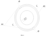
- a mounting and fastening apparatus 44 is further disposed on an outer side wall of the upper tube 40.
- the mounting and fastening apparatus 44 is configured to implement a fixed connection between the entire tubular thick film heater and a protective housing.
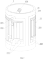
- FIG. 6 to FIG. 10 show a structure of a tubular heater assembly 10 according to an embodiment of the present invention.
- the tubular heater assembly 10 includes an inner tube 1, an outer tube 21, and a heating assembly 20 mounted on an outer peripheral wall of the outer tube 21.
- a spiral flow guide structure 11 is disposed on an outer peripheral wall of the inner tube 1, and the outer tube 21 is sleeved outside the spiral flow guide structure 11.
- the spiral flow guide structure 11, the outer peripheral wall of the inner tube 1, and an inner peripheral wall of the outer tube 21 jointly form a spiral flow channel 14 that a heated liquid passes through.
- the inner peripheral wall of the outer tube 21 is spaced from the spiral flow guide structure 11 by a predetermined radial gap, and the radial gap is disposed so that the inner tube 1 provided with the spiral flow guide structure 11 can be conveniently sleeved inside the outer tube 21, and further liquid can smoothly flow inside the flow channel 14 and the flowing liquid can be adequately heated.
- the inner tube 1 is roughly centered inside the outer tube 21, and the radial gap is equal to one half of a difference between an inner diameter of the outer tube 21 and an outer diameter D of the spiral flow guide structure 11.
- the flow channel 14 is formed between the inner tube 1 provided with the spiral flow guide structure 11 and the outer tube 21, and an opening on at least one end of the flow channel 14 is covered by a sealing end cover (openings at both ends of the flow channel 14 are covered by sealing end covers in this embodiment).
- a cavity wall of the flow channel is provided with a liquid inlet 12 and a liquid outlet 13.
- the sealing end cover is an annular sealing end cover 3, and the annular sealing end cover 3 includes an inner circular wall 31 and an outer circular wall 32 that are concentrically disposed, an upper sealing surface 33 separately connected to an upper portion of the inner circular wall 31 and an upper portion of the outer circular wall 32, and a lower sealing surface 34 separately connected to a lower portion of the inner circular wall 31 and a lower portion of the outer circular wall 32, where the inner circular wall 31 is fastened to an outer peripheral wall termination of the inner tube 1 through sealing, and the outer circular wall 32 is fastened to an inner peripheral wall termination of the outer tube 21 through sealing.
- the liquid to be heated flows along the flow channel 14, and the heating assembly 20 mounted on the outer peripheral wall of the outer tube 21 heats the flowing liquid.
- Heat generated by the heating assembly 20 is exchanged with that of the liquid in the flow channel 14 after passing through the outer tube 21, so as to continuously heat the liquid.
- the annular sealing end cover 3 seals, through welding, the flow channel 14 formed by the inner tube 1 and the outer tube 21, so that the tubular heater assembly 10 can withstand an environment with a high temperature and high pressure.
- the heated liquid flows out of the liquid outlet 13.
- a water pump is disposed at the liquid inlet 12 to continuously deliver pressurized liquid to the spiral flow channel 14.
- the sealing end cover is designed to be the annular sealing end cover 3.
- the annular sealing end cover 3 includes only four surfaces: the inner circular wall 31 and the outer circular wall 32 that are concentrically disposed, and the upper sealing surface 33 and the lower sealing surface 34.
- the foregoing four surfaces are regular surfaces and can be formed only by using a stamping or cutting process, unlike a U-shaped sealing end face, which needs to be stamped and stretched multiple times for formation. Therefore, a processing process is highly simplified, a processing control process is simple, and processing costs are low, while processing efficiency can be greatly improved.
- the inner circular wall is sealed with the outer peripheral wall termination of the inner tube through welding, and the outer circular wall is sealed with the inner peripheral wall termination of the outer tube 21 through welding.
- Laser welding or argon arc welding is preferred.
- a predetermined radial gap between the inner peripheral wall of the outer tube 21 and the spiral flow guide structure 11 is set in a range not greater than 1.0 mm, so that the inner tube 1 provided with the spiral flow guide structure 11 is easily sleeved inside the outer tube 21.
- Such practice further avoids the following situation caused by an overlarge radial gap: the liquid directly flows to the liquid outlet 13 through the radial gap along the length direction of the inner tube 1, instead of being guided through the spiral flow guide structure 11 on the outer peripheral wall of the inner tube 1, and the liquid cannot be adequately heated; or the following situation caused by an excessively small radial gap: the liquid is retained in the spiral flow guide structure 11 and is continuously heated by the heating assembly 20, and as a result, local overheating occurs and the retained liquid in this position is vaporized and discharged, and the liquid is intermittently discharged from the liquid outlet 13 with a large quantity of air bubbles.
- the spiral flow guide structure 11 is formed by a spiral metal wire sleeved on the inner tube 1, and the spiral metal wire is directly exposed to the liquid.
- the spiral metal wire should be a metal material that is insusceptible to rust and is harmless to the human body, so as to avoid blockage of the flow channel 14 caused by bubbles resulted from heating and aging of a wrapper of a rubber material for example, thereby prolonging a service life of the heating apparatus and improving edible safety.
- the spiral metal wire is configured as a stainless steel wire, and the stainless steel wire is welded to the outer peripheral wall of the inner tube 1 to avoid noise generated by shaking inside the flow channel 14; and/or an axial cross-sectional shape of the spiral metal wire is a triangle, a trapezoid, or a rectangle, and the bottom edge of the triangle or the trapezoid is welded onto the outer peripheral wall of the inner tube 1 to form a structure of the flow channel 14 that is simple, easy to produce, and features more stable flow performance.
- two ends of the inner tube 1 are respectively flush with those of the outer tube 21, so that the inner circular wall of the annular sealing end cover 3 is sealed with the outer peripheral wall termination of the inner tube 1 through laser welding, and the outer circular wall of the annular sealing end cover 3 is sealed with the inner peripheral wall termination of the outer tube 21 through laser welding.
- both the inner tube 1 and the outer tube 21 are disposed as stainless steel tubes to further improve edible safety.
- the heating assembly 20 includes an insulation medium layer 211 configured on the outer peripheral wall of the outer tube 21 and a heating circuit 22 configured at the insulation medium layer 211.
- the insulation medium layer 211 is burned on the outer peripheral wall of the outer tube 21, and heat generated by the heating circuit 22 is used to exchange heat of the liquid flowing inside the spiral flow channel 14.
- the wall thickness of the outer tube 21 ranges from 0.5 mm to 1 mm, and that of the inner tube 1 ranges from 0.3 mm to 1 mm.
- the heating circuit 22 includes multiple heating resistors 221 and electrodes 222 that are fastened to the insulation medium layer 211, and two ends of the heating resistor 221 are electrically connected to the electrodes 222. In this way, a power source is connected to the electrodes 222, so that the heating resistors 221 generate heat.
- an extension direction of each of the heating resistors 221 is the same as the length direction of the outer tube 21, and the liquid inlet 12 is connected to a water pump (not shown in the figure).
- the tubular heater assembly 10 further includes a first temperature sensor 223 and a first controller (for example, a PCB is used for control in this embodiment) electrically connected to the first temperature sensor 223.
- the first temperature sensor 223 is configured at a position on the outer tube 21 that is close to the liquid outlet 13. It can be seen from the figure that, in this embodiment, the liquid outlet 13 is disposed on the inner tube 1, and the first temperature sensor 223 is disposed as close to the liquid outlet 13 as possible and may be disposed at a radial position on the outer tube 21 that is closest to the liquid outlet 13.
- the first temperature sensor 223 can approximately detect a liquid temperature at the liquid outlet 13 by detecting a temperature of a tube wall of the outer tube 21 that is close to the liquid outlet 13.
- the PCB controls a water intake speed of the water pump and/or heating power of the heating resistors 221 based on temperature information sent by the first temperature sensor 223.
- the first temperature sensor 223 is disposed at a position that is close to the liquid outlet 13 but is as far away from the heating resistors 221 as possible in the axial direction, so as to accurately detect the liquid temperature at the liquid outlet 13. In this way, the first temperature sensor 223 is configured to detect a discharged-liquid temperature and provide feedback to the PCB.
- the PCB compares actually measured discharged-liquid temperature data with a required discharged-liquid temperature specified by a user to automatically adjust the heating power of the heating resistors 221 or control the water pump to adjust a flow rate of the liquid entering the flow channel 14, thereby implementing accurate control on the discharged-liquid temperature.
- the multiple heating resistors 221 are distributed around the outer peripheral wall of the outer tube 21, and preferably, may be approximately uniformly distributed, so that the heating resistors 221 directly face the liquid in the flow channel 14 to transfer heat to the flowing liquid in a timely manner.
- the tubular heater assembly 10 further includes a second temperature sensor 224, and a second controller (for example, the PCB described above in this embodiment is used as the second controller for control) electrically connected to the second temperature sensor 224.
- the second temperature sensor 224 is disposed on the outer tube 21 and close to the heating resistors, and is configured to detect an outer tube temperature at a location of the second temperature sensor 224.
- the second controller (the PCB) is configured to receive an outer tube temperature sent by the second temperature sensor 224, and when the outer tube temperature is higher than a first preset temperature threshold in a first preset heating time period, control the heating circuit 22 to be disconnected and/or send no-liquid burning warning information. This is because when there is no liquid in the flow channel 14, heat generated by the heating resistors 221 cannot be transmitted to the liquid through an outer tube wall for heat dissipation.
- the PCB may control, based on outer tube temperature information sent by the second temperature sensor 224, the heating circuit to be disconnected and/or to send over-temperature protection warning information, thereby providing dry burning-resistant protection and avoiding the heating assembly 20 from being burned.
- the first temperature sensor 223 and the second temperature sensor 224 are arranged in the length direction of the outer tube 21 to facilitate burnout imprinting and laser adjustment.
- the second temperature sensor 224 may be disposed closer to the liquid outlet 13 than the liquid inlet 12.
- the first temperature sensor 223 is disposed closer to the liquid outlet 13 than the second temperature sensor 224.
- a power density of a heating resistor 221 near the second temperature sensor 224 may be made greater than that of a heating resistor that is circumferentially away from the second temperature sensor 224.
- the second controller (the PCB) is further configured to receive an outer tube temperature sent by the second temperature sensor 224, and when the received outer tube temperature is higher than the second preset temperature threshold within a second preset heating time period, control the heating circuit to be disconnected and/or to send warning information for water scale limit protection.
- a specific principle of water scale detection is as follows: An operating temperature (related to the power density) of the heating resistor 221 near the second temperature sensor 224 is made higher than that of a heating resistor 221 in another area, so that water scale starts to accumulate first around the second temperature sensor 224, and the amount of accumulated water scale is greater than that in another area. After the accumulated water scale reaches a certain degree, as the water scale has a large thermal resistance, that is, a small thermal conductivity coefficient, when the heating resistor 221 continuously transmits heat to the liquid in the flow channel 14, heat generated by the heating resistor 221 in a position with water scale accumulated cannot be transmitted to the liquid in the longitudinal direction through the stainless steel outer tube 21.
- the second temperature sensor 224 detects the outer tube temperature at this time and provides feedback to the PCB, which then sends information to remind the user of clearing the water scale and controls the heating circuit to be disconnected to stop heating, thereby effectively preventing a burning risk caused by local overheating of the heating resistor 221 due to accumulation of water scale.
- a line width of a heating resistor around the second temperature sensor 224 may be reduced to increase a power density of the heating resistor.
- the second temperature sensor 224 provides an integrated detection function, and can implement a dry-burning resistance protection function and a water scale detection and reminding function to optimize functions of the tubular heater assembly 10.
- a method for water scale detection and limit protection is as follows:
- a temperature detected by the second temperature sensor 224 is 55°C to 91 °C.
- water scale starts to accumulate around the second temperature sensor 224.
- a temperature of the heating resistor increases, and heat generated by the heating resistor is horizontally transmitted to the second temperature sensor 224, which then detects an outer tube temperature at this time and provides feedback to the PCB for comparison with a protection threshold (for example, 103°C) preset by the PCB.
- a protection threshold for example, 103°C
- both the liquid inlet 12 and the liquid outlet 13 are disposed on the inner tube 1.
- a position on the inner tube 1 that corresponds to the liquid inlet 12 is provided with a liquid intake conduit 121.
- a position on the inner tube 1 that corresponds to the liquid outlet 13 is provided with a liquid discharge conduit 131.
- At least the liquid intake conduit 121 is disposed obliquely relative to a center line of the inner tube 1 such that the liquid can easily flows in.
- the liquid intake conduit 121 and the liquid discharge conduit 131 are mounted in a cavity formed at the center of the inner tube 1.
- the sealed connection form thereof enables a simple structure, low manufacturing costs, stable performance and a long service life in a high-temperature and high-pressure environment, a high edible safety coefficient for the stainless steel spiral flow channel 14, and a stable discharged-water temperature.
- water scale detection is added, which increases a service life for heating elements. Therefore, the tubular heater assembly 10 has relatively high application and promotion values.
Landscapes
- Engineering & Computer Science (AREA)
- Physics & Mathematics (AREA)
- Thermal Sciences (AREA)
- Mechanical Engineering (AREA)
- General Engineering & Computer Science (AREA)
- Chemical & Material Sciences (AREA)
- Combustion & Propulsion (AREA)
- Geometry (AREA)
- Resistance Heating (AREA)
- Instantaneous Water Boilers, Portable Hot-Water Supply Apparatuses, And Control Of Portable Hot-Water Supply Apparatuses (AREA)
Claims (11)
- Schutzvorrichtung für eine rohrförmige Dickschicht-Heizvorrichtung, die so konfiguriert ist, dass sie einen Schutz für eine rohrförmige Heizanordnung (10, 20) bereitstellt und Folgendes umfasst:ein oberes Rohr (40), wobei das obere Rohr eine obere Rohrseitenfläche (41) aufweist;
undeine Basis (60), wobei ein mittlerer Abschnitt der Basis mit einem kreisförmigen Loch versehen ist, das ein Herausragen einer Flüssigkeitsauslassleitung (131) der rohrförmigen Heizungsanordnung ermöglicht;dadurch gekennzeichnet, dassdas obere Rohr der röhrenförmigen Dickschichtheizungs-Schutzvorrichtung außerdem ein Toroid (42) umfasst;wobei die obere Rohrseitenfläche (41) und das Toroid (42) mit einem Innenraum (70) angeordnet sind,wobei eine äußere Ringfläche des Toroids integral mit einem oberen Abschnitt der oberen Rohrseitenfläche (41) verbunden ist,und ein Radius einer inneren Ringfläche (43) des Toroids kleiner ist als ein Radius einer inneren Seitenfläche einer inneren Röhre (1) der röhrenförmigen Heizungsbaugruppe; wobei sich ein Flansch (45) nach unten entlang der inneren Ringfläche des Toroids erstreckt und ein Raum zwischen dem Flansch (45) und einer inneren Seitenwand der oberen Röhrenseitenfläche (41) eine obere Nut (47) bildet, die geeignet ist, einen oberen Abschnitt der röhrenförmigen Heizungsbaugruppe aufzunehmen; und ein unterer Abschnitt der oberen Röhrenseitenfläche (41) mit einem ersten Verriegelungsmechanismus (46) versehen ist;die Basis ferner mit einer unteren Nut (63) versehen ist, ein Radius einer inneren Seitenfläche der unteren Nut kleiner ist als der Radius der inneren Seitenfläche des inneren Rohrs (1) der rohrförmigen Heizungsbaugruppe, und ein Radius einer äußeren Seitenfläche der unteren Nut größer ist als ein Radius einer äußeren Seitenfläche (41) eines äußeren Rohrs (21) der rohrförmigen Heizungsbaugruppe;die Basis mit einem elastischen Kontaktstück (62) versehen ist; und wenn ein unterer Abschnitt der röhrenförmigen Heizungsbaugruppe auf der unteren Nut montiert ist, kann ein Anschlusskontakt des elastischen Kontaktstücks (62) mit einer Elektrode (222) auf dem Außenrohr der röhrenförmigen Heizungsbaugruppe durch Kontakt verbunden werden;eine Seitenwand oder der Boden der Basis mit einem Verdrahtungsanschluss (65) versehen ist, wobei der Verdrahtungsanschluss elektrisch mit dem elastischen Kontaktstück (62) verbunden ist und der Verdrahtungsanschluss extern mit einer Stromversorgung verbunden werden kann; unddie Basis mit einem zweiten Verriegelungsmechanismus (61) versehen ist, der mit dem ersten Verriegelungsmechanismus (46) zusammenpasst und verriegelt wird. - Rohrförmige Dickschichtheizungs-Schutzvorrichtung nach Anspruch 1, die ferner einen ersten Ringnut-Dichtring (51), der in der oberen Nut angeordnet ist, und einen zweiten Ringnut-Dichtring (52), der in der unteren Nut angeordnet ist, umfasst, wobei eine Nutbreite des ersten Ringnut-Dichtrings einer Breite des oberen Abschnitts der rohrförmigen Heizungsbaugruppe entspricht und eine Nutbreite des zweiten Ringnut-Dichtrings einer Breite des unteren Abschnitts der rohrförmigen Heizungsbaugruppe entspricht.
- Rohrförmige Dickschichtheizungs-Schutzvorrichtung nach Anspruch 1, wobei das obere Rohr (40) ein Zylinder ist, die Basis (60) eine zylindrische Basis ist, die rohrförmige Dickschichtheizungs-Schutzvorrichtung ferner einen ringförmigen Dichtungsring (53) umfasst, der an der zylindrischen Basis angeordnet ist, und der ringförmige Dichtungsring in einem Verbindungsabschnitt zwischen dem Zylinder und der zylindrischen Basis angeordnet ist.
- Röhrenförmige Dickschichtheizungs-Schutzvorrichtung nach Anspruch 3, wobei die Basis mit einer ersten Positionierungsvorrichtung (64) versehen ist und die erste Positionierungsvorrichtung so konfiguriert ist, dass sie eine passende Position zwischen der röhrenförmigen Heizungsbaugruppe und der Basis bestimmt, sodass der Anschlusskontakt des elastischen Kontaktstücks (62) durch Kontakt mit der Elektrode am Außenrohr der röhrenförmigen Heizungsbaugruppe verbunden werden kann.
- Rohrförmige Dickschichtheizungs-Schutzvorrichtung nach Anspruch 4, wobei eine zweite Positionierungsvorrichtung (48) auf dem Flansch angeordnet ist, der sich nach unten entlang der inneren Ringfläche des Toroids erstreckt, und die zweite Positionierungsvorrichtung (48) so konfiguriert ist, dass sie eine passende Position zwischen der rohrförmigen Heizungsbaugruppe und dem oberen Rohr (40) bestimmt, um eine Positionsanpassung zwischen dem ersten Verriegelungsmechanismus und dem zweiten Verriegelungsmechanismus durchzuführen.
- Rohrförmige Dickschichtheizungs-Schutzvorrichtung nach Anspruch 1, wobei der erste Verriegelungsmechanismus (46) einen Clip mit einem Bajonett umfasst und der Clip an einem unteren Abschnitt einer inneren Seitenfläche des oberen Rohrs (40) angeordnet ist;
und der zweite Verriegelungsmechanismus eine elastische Bauteilklammer mit einem Vorsprung umfasst, wobei eine Verriegelungsfunktion durch Anpassen des Vorsprungs der Klammer an das Bajonett des Clips realisiert werden kann;
oder:
der zweite Verriegelungsmechanismus eine Klammer mit einem Bajonett umfasst, der erste Verriegelungsmechanismus eine elastische Bauteilklammer mit einem Vorsprung umfasst und eine Verriegelungsfunktion durch Anpassen des Vorsprungs der Klammer an das Bajonett der Klammer realisiert werden kann; und eine Montage- und Befestigungsvorrichtung (44) an einer äußeren Seitenwand des oberen Rohrs angeordnet ist. - Rohrförmige Dickschichtheizungs-Schutzvorrichtung, umfassend die rohrförmige Dickschichtheizungs-Schutzvorrichtung nach Anspruch 1, und ferner umfassend eine rohrförmige Heizungsanordnung; wobeiein oberer Abschnitt der rohrförmigen Heizungsbaugruppe in die obere Rille und ein unterer Abschnitt der rohrförmigen Heizungsbaugruppe in die untere Rille eingesetzt ist; unddie Rohrheizkörperbaugruppe (10) umfasst:ein Innenrohr (1), wobei eine spiralförmige Strömungsführungsstruktur (11) an einer äußeren Umfangswand des Innenrohrs ausgebildet ist; undein äußeres Rohr (21), wobei das äußere Rohr außerhalb der spiralförmigen Strömungsführungsstruktur (11) mit einer Muffe versehen ist; eine äußere Umfangswand des äußeren Rohrs (21) mit einer Heizanordnung (20) versehen ist;und eine innere Umfangswand des Außenrohrs von der spiralförmigen Strömungsführungsstruktur (11) durch einen vorbestimmten radialen Spalt getrennt ist; wobeiein Strömungskanal (14) zwischen dem Innenrohr und dem Außenrohr gebildet ist und eine Öffnung an mindestens einem Ende des Strömungskanals durch eine abdichtende Endabdeckung (3) abgedeckt ist;und eine Hohlraumwand des Strömungskanals mit einem Flüssigkeitseinlass (12) und einem Flüssigkeitsauslass (13) versehen ist; unddie abdichtende Endabdeckung eine ringförmige abdichtende Endabdeckung (3) ist, und die ringförmige abdichtende Endabdeckung eine innere kreisförmige Wand (31) und eine äußere kreisförmige Wand (32), die konzentrisch angeordnet sind, eine obere abdichtende Oberfläche (33), die separat mit einem oberen Abschnitt der inneren kreisförmigen Wand und einem oberen Abschnitt der äußeren kreisförmigen Wand verbunden ist, und eine untere Dichtungsfläche (34) umfasst, die separat mit einem unteren Abschnitt der inneren kreisförmigen Wand und einem unteren Abschnitt der äußeren kreisförmigen Wand verbunden ist, wobei die innere kreisförmige Wand an einem äußeren Umfangswandabschluss des inneren Rohrs durch Abdichtung befestigt ist und die äußere kreisförmige Wand an einem inneren Umfangswandabschluss des äußeren Rohrs durch Abdichtung befestigt ist.
- Rohrförmiger Dickschichtheizer mit einer Schutzfunktion nach Anspruch 7, wobei die spiralförmige Strömungsführungsstruktur durch einen spiralförmigen Metalldraht gebildet wird, der auf dem Innenrohr ummantelt ist; der spiralförmige Metalldraht ein Draht aus rostfreiem Stahl ist und der Draht aus rostfreiem Stahl an die äußere Umfangswand des Innenrohrs geschweißt ist; und/oder eine axiale Querschnittsform des spiralförmigen Metalldrahtes ein Dreieck, ein Trapez oder ein Rechteck ist, und/oder zwei Enden des Innenrohrs jeweils mit zwei Enden des Außenrohrs bündig sind.
- Rohrförmige Dickschichtheizung mit einer Schutzfunktion nach Anspruch 7, wobei die Heizanordnung eine Isoliermedienschicht (211), die an der äußeren Umfangswand des Außenrohrs ausgebildet ist, und einen Heizkreis (221), der an der Isoliermedienschicht ausgebildet ist, umfasst, wobei der Heizkreis mehrere Heizwiderstände (221) und Elektroden (222) umfasst, die an der Isoliermedienschicht befestigt sind, und wobei zwei Enden des Heizwiderstands jeweils mit den Elektroden elektrisch verbunden sind; und
eine Ausdehnungsrichtung jedes der Heizwiderstände die gleiche ist wie die Längsrichtung des Außenrohrs; der Flüssigkeitseinlass mit einer Wasserpumpe verbunden ist; und die Heizungsbaugruppe ferner einen ersten Temperatursensor (223) und eine erste Steuerung umfasst, die elektrisch mit dem ersten Temperatursensor verbunden ist; wobei der erste Temperatursensor an einer Position auf dem Außenrohr konfiguriert ist, die sich in der Nähe des Flüssigkeitsauslasses befindet, und die erste Steuerung so ausgelegt ist, dass sie eine Flüssigkeitseinlassgeschwindigkeit der Wasserpumpe und/oder die Heizleistung der Heizwiderstände auf der Grundlage von Temperaturinformationen steuert, die von dem ersten Temperatursensor gesendet werden. - Rohrförmige Dickschichtheizung mit einer Schutzfunktion nach Anspruch 9, wobei die mehreren Heizwiderstände um die äußere Umfangswand des Außenrohrs herum verteilt sind; und die Heizungsbaugruppe ferner einen zweiten Temperatursensor (224) und ein zweites Steuergerät umfasst, das elektrisch mit dem zweiten Temperatursensor verbunden ist; wobei der zweite Temperatursensor am Außenrohr und in der Nähe der Heizwiderstände angeordnet ist und so konfiguriert ist, dass er eine Außenrohrtemperatur an einer Position des zweiten Temperatursensors erfasst; und die zweite Steuerung so konfiguriert ist, dass sie die von dem zweiten Temperatursensor gesendete Außenrohrtemperatur empfängt und, wenn die Außenrohrtemperatur in einer ersten voreingestellten Heizzeitperiode höher als ein erster voreingestellter Temperaturschwellenwert ist oder während des Betriebs höher als ein zweiter voreingestellter Temperaturschwellenwert ist, den Heizkreislauf so steuert, dass er abgeschaltet wird und/oder eine Übertemperaturschutz-Warninformation sendet.
- Rohrförmiger Dickschichtheizer mit einer Schutzfunktion nach Anspruch 9, wobei die Heizwiderstände durch ein Edelstahlrohr direkt der spiralförmigen Strömungsführungsstruktur zugewandt sind und eine Innenwand des Außenrohrs, die den Heizwiderständen direkt zugewandt ist, innerhalb des Flüssigkeitsströmungskanals liegt.
Applications Claiming Priority (2)
| Application Number | Priority Date | Filing Date | Title |
|---|---|---|---|
| CN201811295678.1A CN109458729B (zh) | 2018-11-01 | 2018-11-01 | 管式厚膜加热器保护装置及管式厚膜加热器 |
| PCT/CN2018/118201 WO2020087622A1 (zh) | 2018-11-01 | 2018-11-29 | 管式厚膜加热器保护装置及管式厚膜加热器 |
Publications (4)
| Publication Number | Publication Date |
|---|---|
| EP3875868A1 EP3875868A1 (de) | 2021-09-08 |
| EP3875868A4 EP3875868A4 (de) | 2022-04-06 |
| EP3875868B1 true EP3875868B1 (de) | 2023-06-07 |
| EP3875868C0 EP3875868C0 (de) | 2023-06-07 |
Family
ID=65609116
Family Applications (1)
| Application Number | Title | Priority Date | Filing Date |
|---|---|---|---|
| EP18938483.7A Active EP3875868B1 (de) | 2018-11-01 | 2018-11-29 | Schutzvorrichtung für rohrförmigen dickschichtheizer und rohrförmiger dickschichtheizer |
Country Status (4)
| Country | Link |
|---|---|
| US (1) | US12098866B2 (de) |
| EP (1) | EP3875868B1 (de) |
| CN (1) | CN109458729B (de) |
| WO (1) | WO2020087622A1 (de) |
Families Citing this family (17)
| Publication number | Priority date | Publication date | Assignee | Title |
|---|---|---|---|---|
| CN110000975B (zh) * | 2019-05-07 | 2023-06-30 | 安徽安凯汽车股份有限公司 | 一种节能型纯电动客车用薄膜加热器 |
| CN112577186B (zh) * | 2019-09-27 | 2025-04-15 | 浙江绍兴苏泊尔生活电器有限公司 | 加热供水装置及开水器 |
| CN111102735A (zh) * | 2019-12-26 | 2020-05-05 | 佛山市海德精工电子科技有限公司 | 用于液体加热装置的内管及液体加热装置、制造方法 |
| CN113286393B (zh) * | 2020-10-31 | 2024-08-20 | 东海县晶明照明电器有限公司 | 便于聚热的卤素加热管 |
| CN113966018A (zh) * | 2021-11-17 | 2022-01-21 | 中山赛特奥日用科技有限公司 | 一种发热体及其制造方法 |
| CN114353314A (zh) * | 2022-01-18 | 2022-04-15 | 东莞市东思电子技术有限公司 | 一种内置螺纹导流水道的发热圆管组件及其制备工艺 |
| CN115060003A (zh) * | 2022-07-02 | 2022-09-16 | 安徽苏立科技股份有限公司 | 加热器水道及应用该加热器水道的圆管加热器组件 |
| CN115854546B (zh) * | 2022-12-09 | 2025-09-19 | 上海至纯洁净系统科技股份有限公司 | 在线加热装置 |
| CN116347680B (zh) * | 2023-03-16 | 2026-04-21 | 深圳英集芯科技股份有限公司 | 防干烧控制电路 |
| CN116792938B (zh) * | 2023-04-28 | 2026-03-03 | 镇江东方电热有限公司 | 一种大功率直接电阻式加热元件及其使用方法 |
| WO2024250267A1 (zh) * | 2023-06-09 | 2024-12-12 | 深圳和而泰新材料科技有限公司 | 加热装置和热饮设备 |
| CN117433342B (zh) * | 2023-12-18 | 2024-03-12 | 江苏海鹏防腐设备有限公司 | 一种耐腐蚀的板式换热器及其换热方法 |
| CN118031414B (zh) * | 2024-04-11 | 2024-06-11 | 厦门宝益科技有限公司 | 一种可高效维持介质良性换热的厚膜加热器件 |
| CN118499939B (zh) * | 2024-07-18 | 2024-10-11 | 江苏荣亿达温控科技有限公司 | 一种智能控温的油温机及其控制方法 |
| CN119042797B (zh) * | 2024-10-31 | 2025-01-28 | 上海耀杉电子科技有限公司 | 膜加热散热结构 |
| CN119393900B (zh) * | 2025-01-06 | 2025-03-18 | 江苏沃凯氟精密智造有限公司 | 一种液体加热器 |
| CN120111728B (zh) * | 2025-05-09 | 2025-07-04 | 宁波市扬天磁能科技有限公司 | 一种绝电瞬热多层复合厚膜发热体 |
Family Cites Families (27)
| Publication number | Priority date | Publication date | Assignee | Title |
|---|---|---|---|---|
| CA1113533A (en) * | 1978-10-13 | 1981-12-01 | Lynne E. Windsor | Immersion engine heater locking devices |
| US4865014A (en) * | 1989-02-16 | 1989-09-12 | Nelson Thomas E | Water heater and method of fabricating same |
| CN2260983Y (zh) * | 1996-02-13 | 1997-08-27 | 杨荣楷 | 真空镀电热膜热水器 |
| US6632100B1 (en) * | 1997-04-23 | 2003-10-14 | Anthony, Inc. | Lighting system method and apparatus socket assembly lamp insulator assembly and components thereof |
| AU8730501A (en) * | 1997-04-23 | 2002-01-31 | Anthony, Inc. | A ballast circuit |
| ITVE20000013U1 (it) * | 2000-06-29 | 2001-12-29 | Hydor Srl | Dispositivo riscaldatore termostatico per liquidi provvisto di pompa di ricircolo. |
| DE202005004360U1 (de) * | 2005-02-21 | 2005-05-25 | Wolf Gmbh | Wärmetauscher |
| DE102007034370A1 (de) * | 2007-07-24 | 2009-01-29 | Bleckmann Gmbh & Co. Kg | Kompakte hochdruckfähige Spiraldurchfluss-Heizeinheit |
| CA2639260A1 (en) * | 2008-04-18 | 2009-10-18 | Sang Pil Choi | Separable hot water tank |
| US20100046934A1 (en) * | 2008-08-19 | 2010-02-25 | Johnson Gregg C | High thermal transfer spiral flow heat exchanger |
| EP2295887A2 (de) * | 2009-08-28 | 2011-03-16 | Sang Pil Choi | Wassertank mit Dichtelement |
| CN202637235U (zh) * | 2012-07-02 | 2013-01-02 | 黄胜涛 | 防爆型电热水袋 |
| CN103152846B (zh) * | 2013-03-13 | 2014-06-11 | 沈闽江 | 厚膜加热器 |
| EP3019795A1 (de) * | 2013-07-09 | 2016-05-18 | Cast Aluminum Solutions, LLC | Umlaufheizaggregat |
| CN203392401U (zh) * | 2013-08-18 | 2014-01-15 | 河北巨鑫输送工程有限公司 | 一种托辊密封 |
| US20160366940A1 (en) * | 2014-02-28 | 2016-12-22 | Kimree Hi-Tech Inc. | Electronic cigarette and electronic cigarette atomization control method |
| CN105546805B (zh) * | 2016-02-05 | 2018-10-16 | 广西桂仪科技有限公司 | 一种液体加热装置 |
| CN205481783U (zh) * | 2016-02-05 | 2016-08-17 | 佛山市云米电器科技有限公司 | 一种液体加热装置的密封支架结构 |
| CN205381971U (zh) * | 2016-02-05 | 2016-07-13 | 佛山市云米电器科技有限公司 | 一种带有加热装置的净水系统 |
| CN205939663U (zh) * | 2016-07-25 | 2017-02-08 | 宁波励科智能科技有限公司 | 一种改进后的电热水器 |
| CN206603236U (zh) * | 2017-01-10 | 2017-11-03 | 深圳市艾维普思科技股份有限公司 | 电子烟 |
| CN106595030A (zh) * | 2017-03-03 | 2017-04-26 | 佛山吉宝信息科技有限公司 | 一种新型即热式恒温电热水器 |
| CN206739592U (zh) * | 2017-04-05 | 2017-12-12 | 胡小庆 | 一种电磁加热发热体及具有其的热水器、液体加热器 |
| CN108458474A (zh) * | 2018-02-05 | 2018-08-28 | 佛山市海德精工电子科技有限公司 | 一种液体加热装置 |
| CN108449814A (zh) * | 2018-05-17 | 2018-08-24 | 佛山市海德精工电子科技有限公司 | 一种加热器 |
| CN209541145U (zh) * | 2018-11-01 | 2019-10-25 | 佛山市海德精工电子科技有限公司 | 管式厚膜加热器保护装置及管式厚膜加热器 |
| CN109682072B (zh) * | 2019-02-01 | 2024-05-03 | 宁波飞羽集团有限公司 | 电热水器 |
-
2018
- 2018-11-01 CN CN201811295678.1A patent/CN109458729B/zh active Active
- 2018-11-29 WO PCT/CN2018/118201 patent/WO2020087622A1/zh not_active Ceased
- 2018-11-29 EP EP18938483.7A patent/EP3875868B1/de active Active
-
2021
- 2021-04-27 US US17/242,243 patent/US12098866B2/en active Active
Also Published As
| Publication number | Publication date |
|---|---|
| CN109458729B (zh) | 2025-06-03 |
| EP3875868A4 (de) | 2022-04-06 |
| WO2020087622A1 (zh) | 2020-05-07 |
| EP3875868C0 (de) | 2023-06-07 |
| EP3875868A1 (de) | 2021-09-08 |
| US12098866B2 (en) | 2024-09-24 |
| US20210247101A1 (en) | 2021-08-12 |
| CN109458729A (zh) | 2019-03-12 |
Similar Documents
| Publication | Publication Date | Title |
|---|---|---|
| US12098866B2 (en) | Tubular thick film heater protection apparatus and tubular thick film heater | |
| WO2019148785A1 (zh) | 一种液体加热装置 | |
| US20240373515A1 (en) | Tubular thick film heater protection apparatus and tubular thick film heater | |
| CN221153022U (zh) | 发热组件和气溶胶生成装置 | |
| CA2797572C (en) | Flow through heater | |
| CN104272862B (zh) | 加热装置 | |
| US6732677B2 (en) | Bracket for water heater | |
| JP2005132087A (ja) | 埋め込み型ヒータ及び取り外し可能型ヒータを備えた射出成形ノズル | |
| CN110801157A (zh) | 一种液体加热装置 | |
| CN209101545U (zh) | 一种液体加热装置 | |
| US11306945B2 (en) | Heating system for heating a fluid medium | |
| CN209541145U (zh) | 管式厚膜加热器保护装置及管式厚膜加热器 | |
| CN114738321B (zh) | 一种刀片式加热泵盖及加热泵 | |
| JP2004270954A (ja) | 流体加熱装置 | |
| JP2006250458A (ja) | ガスコンロ | |
| CN213248461U (zh) | 加热装置和饮水机 | |
| JP3865822B2 (ja) | 流水の間接加熱装置 | |
| KR200472641Y1 (ko) | 밀착유도부를 구비하는 가열장치 | |
| KR102909895B1 (ko) | 차량용 가열장치 | |
| CN223896032U (zh) | 灶具 | |
| CN211716626U (zh) | 一种便于检知温度的烹饪器具 | |
| WO2025050836A1 (zh) | 发热组件和气溶胶生成装置 | |
| CN223799288U (zh) | 雾化组件及雾化器 | |
| JPH10160589A (ja) | サーミスタ型温度センサー | |
| WO2025050841A1 (zh) | 发热组件和气溶胶生成装置 |
Legal Events
| Date | Code | Title | Description |
|---|---|---|---|
| STAA | Information on the status of an ep patent application or granted ep patent |
Free format text: STATUS: THE INTERNATIONAL PUBLICATION HAS BEEN MADE |
|
| PUAI | Public reference made under article 153(3) epc to a published international application that has entered the european phase |
Free format text: ORIGINAL CODE: 0009012 |
|
| STAA | Information on the status of an ep patent application or granted ep patent |
Free format text: STATUS: REQUEST FOR EXAMINATION WAS MADE |
|
| 17P | Request for examination filed |
Effective date: 20210601 |
|
| AK | Designated contracting states |
Kind code of ref document: A1 Designated state(s): AL AT BE BG CH CY CZ DE DK EE ES FI FR GB GR HR HU IE IS IT LI LT LU LV MC MK MT NL NO PL PT RO RS SE SI SK SM TR |
|
| RIC1 | Information provided on ipc code assigned before grant |
Ipc: F24H 9/02 20060101ALI20211129BHEP Ipc: F24H 1/14 20060101AFI20211129BHEP |
|
| DAV | Request for validation of the european patent (deleted) | ||
| DAX | Request for extension of the european patent (deleted) | ||
| A4 | Supplementary search report drawn up and despatched |
Effective date: 20220307 |
|
| RIC1 | Information provided on ipc code assigned before grant |
Ipc: F24H 9/02 20060101ALI20220301BHEP Ipc: F24H 1/14 20060101AFI20220301BHEP |
|
| GRAP | Despatch of communication of intention to grant a patent |
Free format text: ORIGINAL CODE: EPIDOSNIGR1 |
|
| STAA | Information on the status of an ep patent application or granted ep patent |
Free format text: STATUS: GRANT OF PATENT IS INTENDED |
|
| INTG | Intention to grant announced |
Effective date: 20221128 |
|
| GRAS | Grant fee paid |
Free format text: ORIGINAL CODE: EPIDOSNIGR3 |
|
| GRAA | (expected) grant |
Free format text: ORIGINAL CODE: 0009210 |
|
| STAA | Information on the status of an ep patent application or granted ep patent |
Free format text: STATUS: THE PATENT HAS BEEN GRANTED |
|
| AK | Designated contracting states |
Kind code of ref document: B1 Designated state(s): AL AT BE BG CH CY CZ DE DK EE ES FI FR GB GR HR HU IE IS IT LI LT LU LV MC MK MT NL NO PL PT RO RS SE SI SK SM TR |
|
| REG | Reference to a national code |
Ref country code: GB Ref legal event code: FG4D |
|
| REG | Reference to a national code |
Ref country code: CH Ref legal event code: EP Ref country code: AT Ref legal event code: REF Ref document number: 1576190 Country of ref document: AT Kind code of ref document: T Effective date: 20230615 |
|
| REG | Reference to a national code |
Ref country code: DE Ref legal event code: R096 Ref document number: 602018051707 Country of ref document: DE |
|
| U01 | Request for unitary effect filed |
Effective date: 20230703 |
|
| U07 | Unitary effect registered |
Designated state(s): AT BE BG DE DK EE FI FR IT LT LU LV MT NL PT SE SI Effective date: 20230710 |
|
| REG | Reference to a national code |
Ref country code: LT Ref legal event code: MG9D |
|
| PG25 | Lapsed in a contracting state [announced via postgrant information from national office to epo] |
Ref country code: NO Free format text: LAPSE BECAUSE OF FAILURE TO SUBMIT A TRANSLATION OF THE DESCRIPTION OR TO PAY THE FEE WITHIN THE PRESCRIBED TIME-LIMIT Effective date: 20230907 Ref country code: ES Free format text: LAPSE BECAUSE OF FAILURE TO SUBMIT A TRANSLATION OF THE DESCRIPTION OR TO PAY THE FEE WITHIN THE PRESCRIBED TIME-LIMIT Effective date: 20230607 |
|
| PG25 | Lapsed in a contracting state [announced via postgrant information from national office to epo] |
Ref country code: RS Free format text: LAPSE BECAUSE OF FAILURE TO SUBMIT A TRANSLATION OF THE DESCRIPTION OR TO PAY THE FEE WITHIN THE PRESCRIBED TIME-LIMIT Effective date: 20230607 Ref country code: HR Free format text: LAPSE BECAUSE OF FAILURE TO SUBMIT A TRANSLATION OF THE DESCRIPTION OR TO PAY THE FEE WITHIN THE PRESCRIBED TIME-LIMIT Effective date: 20230607 Ref country code: GR Free format text: LAPSE BECAUSE OF FAILURE TO SUBMIT A TRANSLATION OF THE DESCRIPTION OR TO PAY THE FEE WITHIN THE PRESCRIBED TIME-LIMIT Effective date: 20230908 |
|
| U20 | Renewal fee for the european patent with unitary effect paid |
Year of fee payment: 6 Effective date: 20231122 |
|
| PG25 | Lapsed in a contracting state [announced via postgrant information from national office to epo] |
Ref country code: SK Free format text: LAPSE BECAUSE OF FAILURE TO SUBMIT A TRANSLATION OF THE DESCRIPTION OR TO PAY THE FEE WITHIN THE PRESCRIBED TIME-LIMIT Effective date: 20230607 |
|
| PG25 | Lapsed in a contracting state [announced via postgrant information from national office to epo] |
Ref country code: IS Free format text: LAPSE BECAUSE OF FAILURE TO SUBMIT A TRANSLATION OF THE DESCRIPTION OR TO PAY THE FEE WITHIN THE PRESCRIBED TIME-LIMIT Effective date: 20231007 |
|
| PG25 | Lapsed in a contracting state [announced via postgrant information from national office to epo] |
Ref country code: SM Free format text: LAPSE BECAUSE OF FAILURE TO SUBMIT A TRANSLATION OF THE DESCRIPTION OR TO PAY THE FEE WITHIN THE PRESCRIBED TIME-LIMIT Effective date: 20230607 Ref country code: SK Free format text: LAPSE BECAUSE OF FAILURE TO SUBMIT A TRANSLATION OF THE DESCRIPTION OR TO PAY THE FEE WITHIN THE PRESCRIBED TIME-LIMIT Effective date: 20230607 Ref country code: RO Free format text: LAPSE BECAUSE OF FAILURE TO SUBMIT A TRANSLATION OF THE DESCRIPTION OR TO PAY THE FEE WITHIN THE PRESCRIBED TIME-LIMIT Effective date: 20230607 Ref country code: IS Free format text: LAPSE BECAUSE OF FAILURE TO SUBMIT A TRANSLATION OF THE DESCRIPTION OR TO PAY THE FEE WITHIN THE PRESCRIBED TIME-LIMIT Effective date: 20231007 Ref country code: CZ Free format text: LAPSE BECAUSE OF FAILURE TO SUBMIT A TRANSLATION OF THE DESCRIPTION OR TO PAY THE FEE WITHIN THE PRESCRIBED TIME-LIMIT Effective date: 20230607 |
|
| PG25 | Lapsed in a contracting state [announced via postgrant information from national office to epo] |
Ref country code: PL Free format text: LAPSE BECAUSE OF FAILURE TO SUBMIT A TRANSLATION OF THE DESCRIPTION OR TO PAY THE FEE WITHIN THE PRESCRIBED TIME-LIMIT Effective date: 20230607 |
|
| REG | Reference to a national code |
Ref country code: DE Ref legal event code: R097 Ref document number: 602018051707 Country of ref document: DE |
|
| PLBE | No opposition filed within time limit |
Free format text: ORIGINAL CODE: 0009261 |
|
| STAA | Information on the status of an ep patent application or granted ep patent |
Free format text: STATUS: NO OPPOSITION FILED WITHIN TIME LIMIT |
|
| 26N | No opposition filed |
Effective date: 20240308 |
|
| PG25 | Lapsed in a contracting state [announced via postgrant information from national office to epo] |
Ref country code: MC Free format text: LAPSE BECAUSE OF FAILURE TO SUBMIT A TRANSLATION OF THE DESCRIPTION OR TO PAY THE FEE WITHIN THE PRESCRIBED TIME-LIMIT Effective date: 20230607 |
|
| PG25 | Lapsed in a contracting state [announced via postgrant information from national office to epo] |
Ref country code: MC Free format text: LAPSE BECAUSE OF FAILURE TO SUBMIT A TRANSLATION OF THE DESCRIPTION OR TO PAY THE FEE WITHIN THE PRESCRIBED TIME-LIMIT Effective date: 20230607 |
|
| REG | Reference to a national code |
Ref country code: IE Ref legal event code: MM4A |
|
| PG25 | Lapsed in a contracting state [announced via postgrant information from national office to epo] |
Ref country code: IE Free format text: LAPSE BECAUSE OF NON-PAYMENT OF DUE FEES Effective date: 20231129 |
|
| PG25 | Lapsed in a contracting state [announced via postgrant information from national office to epo] |
Ref country code: IE Free format text: LAPSE BECAUSE OF NON-PAYMENT OF DUE FEES Effective date: 20231129 |
|
| U21 | Renewal fee for the european patent with unitary effect paid with additional fee |
Year of fee payment: 7 Effective date: 20250326 |
|
| PG25 | Lapsed in a contracting state [announced via postgrant information from national office to epo] |
Ref country code: CY Free format text: LAPSE BECAUSE OF FAILURE TO SUBMIT A TRANSLATION OF THE DESCRIPTION OR TO PAY THE FEE WITHIN THE PRESCRIBED TIME-LIMIT; INVALID AB INITIO Effective date: 20181129 |
|
| PG25 | Lapsed in a contracting state [announced via postgrant information from national office to epo] |
Ref country code: HU Free format text: LAPSE BECAUSE OF FAILURE TO SUBMIT A TRANSLATION OF THE DESCRIPTION OR TO PAY THE FEE WITHIN THE PRESCRIBED TIME-LIMIT; INVALID AB INITIO Effective date: 20181129 |
|
| U1N | Appointed representative for the unitary patent procedure changed after the registration of the unitary effect |
Representative=s name: SANTARELLI; FR |
|
| U20 | Renewal fee for the european patent with unitary effect paid |
Year of fee payment: 8 Effective date: 20251105 |
|
| PG25 | Lapsed in a contracting state [announced via postgrant information from national office to epo] |
Ref country code: TR Free format text: LAPSE BECAUSE OF FAILURE TO SUBMIT A TRANSLATION OF THE DESCRIPTION OR TO PAY THE FEE WITHIN THE PRESCRIBED TIME-LIMIT Effective date: 20230607 |
|
| PGFP | Annual fee paid to national office [announced via postgrant information from national office to epo] |
Ref country code: GB Payment date: 20251024 Year of fee payment: 8 |
|
| REG | Reference to a national code |
Ref country code: CH Ref legal event code: U11 Free format text: ST27 STATUS EVENT CODE: U-0-0-U10-U11 (AS PROVIDED BY THE NATIONAL OFFICE) Effective date: 20260122 |
|
| PGFP | Annual fee paid to national office [announced via postgrant information from national office to epo] |
Ref country code: CH Payment date: 20260122 Year of fee payment: 8 |