EP3875243B1 - Laminatherstellungsverfahren und herstellungsvorrichtung - Google Patents
Laminatherstellungsverfahren und herstellungsvorrichtung Download PDFInfo
- Publication number
- EP3875243B1 EP3875243B1 EP19878886.1A EP19878886A EP3875243B1 EP 3875243 B1 EP3875243 B1 EP 3875243B1 EP 19878886 A EP19878886 A EP 19878886A EP 3875243 B1 EP3875243 B1 EP 3875243B1
- Authority
- EP
- European Patent Office
- Prior art keywords
- elastomer
- film
- sheet
- roll
- cooling
- Prior art date
- Legal status (The legal status is an assumption and is not a legal conclusion. Google has not performed a legal analysis and makes no representation as to the accuracy of the status listed.)
- Active
Links
Images


Classifications
-
- B—PERFORMING OPERATIONS; TRANSPORTING
- B29—WORKING OF PLASTICS; WORKING OF SUBSTANCES IN A PLASTIC STATE IN GENERAL
- B29C—SHAPING OR JOINING OF PLASTICS; SHAPING OF MATERIAL IN A PLASTIC STATE, NOT OTHERWISE PROVIDED FOR; AFTER-TREATMENT OF THE SHAPED PRODUCTS, e.g. REPAIRING
- B29C48/00—Extrusion moulding, i.e. expressing the moulding material through a die or nozzle which imparts the desired form; Apparatus therefor
- B29C48/001—Combinations of extrusion moulding with other shaping operations
- B29C48/0018—Combinations of extrusion moulding with other shaping operations combined with shaping by orienting, stretching or shrinking, e.g. film blowing
-
- B—PERFORMING OPERATIONS; TRANSPORTING
- B29—WORKING OF PLASTICS; WORKING OF SUBSTANCES IN A PLASTIC STATE IN GENERAL
- B29C—SHAPING OR JOINING OF PLASTICS; SHAPING OF MATERIAL IN A PLASTIC STATE, NOT OTHERWISE PROVIDED FOR; AFTER-TREATMENT OF THE SHAPED PRODUCTS, e.g. REPAIRING
- B29C48/00—Extrusion moulding, i.e. expressing the moulding material through a die or nozzle which imparts the desired form; Apparatus therefor
- B29C48/001—Combinations of extrusion moulding with other shaping operations
- B29C48/0021—Combinations of extrusion moulding with other shaping operations combined with joining, lining or laminating
-
- B—PERFORMING OPERATIONS; TRANSPORTING
- B29—WORKING OF PLASTICS; WORKING OF SUBSTANCES IN A PLASTIC STATE IN GENERAL
- B29C—SHAPING OR JOINING OF PLASTICS; SHAPING OF MATERIAL IN A PLASTIC STATE, NOT OTHERWISE PROVIDED FOR; AFTER-TREATMENT OF THE SHAPED PRODUCTS, e.g. REPAIRING
- B29C48/00—Extrusion moulding, i.e. expressing the moulding material through a die or nozzle which imparts the desired form; Apparatus therefor
- B29C48/03—Extrusion moulding, i.e. expressing the moulding material through a die or nozzle which imparts the desired form; Apparatus therefor characterised by the shape of the extruded material at extrusion
- B29C48/07—Flat, e.g. panels
- B29C48/08—Flat, e.g. panels flexible, e.g. films
-
- B—PERFORMING OPERATIONS; TRANSPORTING
- B29—WORKING OF PLASTICS; WORKING OF SUBSTANCES IN A PLASTIC STATE IN GENERAL
- B29C—SHAPING OR JOINING OF PLASTICS; SHAPING OF MATERIAL IN A PLASTIC STATE, NOT OTHERWISE PROVIDED FOR; AFTER-TREATMENT OF THE SHAPED PRODUCTS, e.g. REPAIRING
- B29C48/00—Extrusion moulding, i.e. expressing the moulding material through a die or nozzle which imparts the desired form; Apparatus therefor
- B29C48/15—Extrusion moulding, i.e. expressing the moulding material through a die or nozzle which imparts the desired form; Apparatus therefor incorporating preformed parts or layers, e.g. extrusion moulding around inserts
- B29C48/154—Coating solid articles, i.e. non-hollow articles
-
- B—PERFORMING OPERATIONS; TRANSPORTING
- B29—WORKING OF PLASTICS; WORKING OF SUBSTANCES IN A PLASTIC STATE IN GENERAL
- B29C—SHAPING OR JOINING OF PLASTICS; SHAPING OF MATERIAL IN A PLASTIC STATE, NOT OTHERWISE PROVIDED FOR; AFTER-TREATMENT OF THE SHAPED PRODUCTS, e.g. REPAIRING
- B29C48/00—Extrusion moulding, i.e. expressing the moulding material through a die or nozzle which imparts the desired form; Apparatus therefor
- B29C48/16—Articles comprising two or more components, e.g. co-extruded layers
- B29C48/18—Articles comprising two or more components, e.g. co-extruded layers the components being layers
- B29C48/21—Articles comprising two or more components, e.g. co-extruded layers the components being layers the layers being joined at their surfaces
-
- B—PERFORMING OPERATIONS; TRANSPORTING
- B29—WORKING OF PLASTICS; WORKING OF SUBSTANCES IN A PLASTIC STATE IN GENERAL
- B29C—SHAPING OR JOINING OF PLASTICS; SHAPING OF MATERIAL IN A PLASTIC STATE, NOT OTHERWISE PROVIDED FOR; AFTER-TREATMENT OF THE SHAPED PRODUCTS, e.g. REPAIRING
- B29C48/00—Extrusion moulding, i.e. expressing the moulding material through a die or nozzle which imparts the desired form; Apparatus therefor
- B29C48/25—Component parts, details or accessories; Auxiliary operations
- B29C48/88—Thermal treatment of the stream of extruded material, e.g. cooling
- B29C48/911—Cooling
- B29C48/9135—Cooling of flat articles, e.g. using specially adapted supporting means
- B29C48/914—Cooling drums
-
- B—PERFORMING OPERATIONS; TRANSPORTING
- B29—WORKING OF PLASTICS; WORKING OF SUBSTANCES IN A PLASTIC STATE IN GENERAL
- B29C—SHAPING OR JOINING OF PLASTICS; SHAPING OF MATERIAL IN A PLASTIC STATE, NOT OTHERWISE PROVIDED FOR; AFTER-TREATMENT OF THE SHAPED PRODUCTS, e.g. REPAIRING
- B29C65/00—Joining or sealing of preformed parts, e.g. welding of plastics materials; Apparatus therefor
- B29C65/02—Joining or sealing of preformed parts, e.g. welding of plastics materials; Apparatus therefor by heating, with or without pressure
- B29C65/08—Joining or sealing of preformed parts, e.g. welding of plastics materials; Apparatus therefor by heating, with or without pressure using ultrasonic vibrations
- B29C65/083—Joining or sealing of preformed parts, e.g. welding of plastics materials; Apparatus therefor by heating, with or without pressure using ultrasonic vibrations using a rotary sonotrode or a rotary anvil
- B29C65/086—Joining or sealing of preformed parts, e.g. welding of plastics materials; Apparatus therefor by heating, with or without pressure using ultrasonic vibrations using a rotary sonotrode or a rotary anvil using a rotary anvil
-
- B—PERFORMING OPERATIONS; TRANSPORTING
- B32—LAYERED PRODUCTS
- B32B—LAYERED PRODUCTS, i.e. PRODUCTS BUILT-UP OF STRATA OF FLAT OR NON-FLAT, e.g. CELLULAR OR HONEYCOMB, FORM
- B32B25/00—Layered products comprising a layer of natural or synthetic rubber
- B32B25/10—Layered products comprising a layer of natural or synthetic rubber next to a fibrous or filamentary layer
-
- B—PERFORMING OPERATIONS; TRANSPORTING
- B32—LAYERED PRODUCTS
- B32B—LAYERED PRODUCTS, i.e. PRODUCTS BUILT-UP OF STRATA OF FLAT OR NON-FLAT, e.g. CELLULAR OR HONEYCOMB, FORM
- B32B37/00—Methods or apparatus for laminating, e.g. by curing or by ultrasonic bonding
- B32B37/0046—Methods or apparatus for laminating, e.g. by curing or by ultrasonic bonding characterised by constructional aspects of the apparatus
- B32B37/0053—Constructional details of laminating machines comprising rollers; Constructional features of the rollers
-
- B—PERFORMING OPERATIONS; TRANSPORTING
- B32—LAYERED PRODUCTS
- B32B—LAYERED PRODUCTS, i.e. PRODUCTS BUILT-UP OF STRATA OF FLAT OR NON-FLAT, e.g. CELLULAR OR HONEYCOMB, FORM
- B32B37/00—Methods or apparatus for laminating, e.g. by curing or by ultrasonic bonding
- B32B37/14—Methods or apparatus for laminating, e.g. by curing or by ultrasonic bonding characterised by the properties of the layers
- B32B37/144—Methods or apparatus for laminating, e.g. by curing or by ultrasonic bonding characterised by the properties of the layers using layers with different mechanical or chemical conditions or properties, e.g. layers with different thermal shrinkage, layers under tension during bonding
-
- B—PERFORMING OPERATIONS; TRANSPORTING
- B32—LAYERED PRODUCTS
- B32B—LAYERED PRODUCTS, i.e. PRODUCTS BUILT-UP OF STRATA OF FLAT OR NON-FLAT, e.g. CELLULAR OR HONEYCOMB, FORM
- B32B38/00—Ancillary operations in connection with laminating processes
- B32B38/0012—Mechanical treatment, e.g. roughening, deforming, stretching
-
- B—PERFORMING OPERATIONS; TRANSPORTING
- B32—LAYERED PRODUCTS
- B32B—LAYERED PRODUCTS, i.e. PRODUCTS BUILT-UP OF STRATA OF FLAT OR NON-FLAT, e.g. CELLULAR OR HONEYCOMB, FORM
- B32B41/00—Arrangements for controlling or monitoring lamination processes; Safety arrangements
-
- B—PERFORMING OPERATIONS; TRANSPORTING
- B32—LAYERED PRODUCTS
- B32B—LAYERED PRODUCTS, i.e. PRODUCTS BUILT-UP OF STRATA OF FLAT OR NON-FLAT, e.g. CELLULAR OR HONEYCOMB, FORM
- B32B5/00—Layered products characterised by the non- homogeneity or physical structure, i.e. comprising a fibrous, filamentary, particulate or foam layer; Layered products characterised by having a layer differing constitutionally or physically in different parts
- B32B5/02—Layered products characterised by the non- homogeneity or physical structure, i.e. comprising a fibrous, filamentary, particulate or foam layer; Layered products characterised by having a layer differing constitutionally or physically in different parts characterised by structural features of a fibrous or filamentary layer
- B32B5/022—Non-woven fabric
-
- B—PERFORMING OPERATIONS; TRANSPORTING
- B29—WORKING OF PLASTICS; WORKING OF SUBSTANCES IN A PLASTIC STATE IN GENERAL
- B29C—SHAPING OR JOINING OF PLASTICS; SHAPING OF MATERIAL IN A PLASTIC STATE, NOT OTHERWISE PROVIDED FOR; AFTER-TREATMENT OF THE SHAPED PRODUCTS, e.g. REPAIRING
- B29C48/00—Extrusion moulding, i.e. expressing the moulding material through a die or nozzle which imparts the desired form; Apparatus therefor
- B29C48/001—Combinations of extrusion moulding with other shaping operations
- B29C48/0022—Combinations of extrusion moulding with other shaping operations combined with cutting
-
- B—PERFORMING OPERATIONS; TRANSPORTING
- B29—WORKING OF PLASTICS; WORKING OF SUBSTANCES IN A PLASTIC STATE IN GENERAL
- B29C—SHAPING OR JOINING OF PLASTICS; SHAPING OF MATERIAL IN A PLASTIC STATE, NOT OTHERWISE PROVIDED FOR; AFTER-TREATMENT OF THE SHAPED PRODUCTS, e.g. REPAIRING
- B29C48/00—Extrusion moulding, i.e. expressing the moulding material through a die or nozzle which imparts the desired form; Apparatus therefor
- B29C48/25—Component parts, details or accessories; Auxiliary operations
- B29C48/30—Extrusion nozzles or dies
- B29C48/305—Extrusion nozzles or dies having a wide opening, e.g. for forming sheets
-
- B—PERFORMING OPERATIONS; TRANSPORTING
- B29—WORKING OF PLASTICS; WORKING OF SUBSTANCES IN A PLASTIC STATE IN GENERAL
- B29K—INDEXING SCHEME ASSOCIATED WITH SUBCLASSES B29B, B29C OR B29D, RELATING TO MOULDING MATERIALS OR TO MATERIALS FOR MOULDS, REINFORCEMENTS, FILLERS OR PREFORMED PARTS, e.g. INSERTS
- B29K2021/00—Use of unspecified rubbers as moulding material
- B29K2021/003—Thermoplastic elastomers
-
- B—PERFORMING OPERATIONS; TRANSPORTING
- B29—WORKING OF PLASTICS; WORKING OF SUBSTANCES IN A PLASTIC STATE IN GENERAL
- B29L—INDEXING SCHEME ASSOCIATED WITH SUBCLASS B29C, RELATING TO PARTICULAR ARTICLES
- B29L2007/00—Flat articles, e.g. films or sheets
- B29L2007/008—Wide strips, e.g. films, webs
-
- B—PERFORMING OPERATIONS; TRANSPORTING
- B29—WORKING OF PLASTICS; WORKING OF SUBSTANCES IN A PLASTIC STATE IN GENERAL
- B29L—INDEXING SCHEME ASSOCIATED WITH SUBCLASS B29C, RELATING TO PARTICULAR ARTICLES
- B29L2009/00—Layered products
-
- B—PERFORMING OPERATIONS; TRANSPORTING
- B32—LAYERED PRODUCTS
- B32B—LAYERED PRODUCTS, i.e. PRODUCTS BUILT-UP OF STRATA OF FLAT OR NON-FLAT, e.g. CELLULAR OR HONEYCOMB, FORM
- B32B38/00—Ancillary operations in connection with laminating processes
- B32B38/0012—Mechanical treatment, e.g. roughening, deforming, stretching
- B32B2038/0028—Stretching, elongating
-
- B—PERFORMING OPERATIONS; TRANSPORTING
- B32—LAYERED PRODUCTS
- B32B—LAYERED PRODUCTS, i.e. PRODUCTS BUILT-UP OF STRATA OF FLAT OR NON-FLAT, e.g. CELLULAR OR HONEYCOMB, FORM
- B32B41/00—Arrangements for controlling or monitoring lamination processes; Safety arrangements
- B32B2041/06—Starting the lamination machine or method
-
- B—PERFORMING OPERATIONS; TRANSPORTING
- B32—LAYERED PRODUCTS
- B32B—LAYERED PRODUCTS, i.e. PRODUCTS BUILT-UP OF STRATA OF FLAT OR NON-FLAT, e.g. CELLULAR OR HONEYCOMB, FORM
- B32B2305/00—Condition, form or state of the layers or laminate
- B32B2305/10—Fibres of continuous length
- B32B2305/20—Fibres of continuous length in the form of a non-woven mat
-
- B—PERFORMING OPERATIONS; TRANSPORTING
- B32—LAYERED PRODUCTS
- B32B—LAYERED PRODUCTS, i.e. PRODUCTS BUILT-UP OF STRATA OF FLAT OR NON-FLAT, e.g. CELLULAR OR HONEYCOMB, FORM
- B32B2555/00—Personal care
- B32B2555/02—Diapers or napkins
-
- B—PERFORMING OPERATIONS; TRANSPORTING
- B32—LAYERED PRODUCTS
- B32B—LAYERED PRODUCTS, i.e. PRODUCTS BUILT-UP OF STRATA OF FLAT OR NON-FLAT, e.g. CELLULAR OR HONEYCOMB, FORM
- B32B37/00—Methods or apparatus for laminating, e.g. by curing or by ultrasonic bonding
- B32B37/04—Methods or apparatus for laminating, e.g. by curing or by ultrasonic bonding characterised by the partial melting of at least one layer
-
- B—PERFORMING OPERATIONS; TRANSPORTING
- B32—LAYERED PRODUCTS
- B32B—LAYERED PRODUCTS, i.e. PRODUCTS BUILT-UP OF STRATA OF FLAT OR NON-FLAT, e.g. CELLULAR OR HONEYCOMB, FORM
- B32B37/00—Methods or apparatus for laminating, e.g. by curing or by ultrasonic bonding
- B32B37/08—Methods or apparatus for laminating, e.g. by curing or by ultrasonic bonding characterised by the cooling method
-
- B—PERFORMING OPERATIONS; TRANSPORTING
- B32—LAYERED PRODUCTS
- B32B—LAYERED PRODUCTS, i.e. PRODUCTS BUILT-UP OF STRATA OF FLAT OR NON-FLAT, e.g. CELLULAR OR HONEYCOMB, FORM
- B32B37/00—Methods or apparatus for laminating, e.g. by curing or by ultrasonic bonding
- B32B37/14—Methods or apparatus for laminating, e.g. by curing or by ultrasonic bonding characterised by the properties of the layers
- B32B37/15—Methods or apparatus for laminating, e.g. by curing or by ultrasonic bonding characterised by the properties of the layers with at least one layer being manufactured and immediately laminated before reaching its stable state, e.g. in which a layer is extruded and laminated while in semi-molten state
- B32B37/153—Methods or apparatus for laminating, e.g. by curing or by ultrasonic bonding characterised by the properties of the layers with at least one layer being manufactured and immediately laminated before reaching its stable state, e.g. in which a layer is extruded and laminated while in semi-molten state at least one layer is extruded and immediately laminated while in semi-molten state
-
- B—PERFORMING OPERATIONS; TRANSPORTING
- B32—LAYERED PRODUCTS
- B32B—LAYERED PRODUCTS, i.e. PRODUCTS BUILT-UP OF STRATA OF FLAT OR NON-FLAT, e.g. CELLULAR OR HONEYCOMB, FORM
- B32B37/00—Methods or apparatus for laminating, e.g. by curing or by ultrasonic bonding
- B32B37/14—Methods or apparatus for laminating, e.g. by curing or by ultrasonic bonding characterised by the properties of the layers
- B32B37/16—Methods or apparatus for laminating, e.g. by curing or by ultrasonic bonding characterised by the properties of the layers with all layers existing as coherent layers before laminating
- B32B37/20—Methods or apparatus for laminating, e.g. by curing or by ultrasonic bonding characterised by the properties of the layers with all layers existing as coherent layers before laminating involving the assembly of continuous webs only
- B32B37/203—One or more of the layers being plastic
- B32B37/206—Laminating a continuous layer between two continuous plastic layers
Definitions
- the present invention relates to a manufacturing method and a manufacturing apparatus for laminate usable in a part of a disposable absorbent article such as a disposable diaper and the like.
- Patent Literature 1 JP H10-29259A (FIGS. 4 and 5)
- JP 2001 032160 A discloses to provide a composite sheet which comprises a nonwoven fabric and an elastomer, and has large elasticity in one direction, but is little elastic in the other direction.
- This composite sheet comprises a nonwoven fabric and the strands of a thermoplastic elastomer joined to the nonwoven fabric.
- the nonwoven fabric is formed by arranging filaments in the longitudinal direction of the nonwoven fabric and then drawing the filaments.
- the strands of the elastomer are arranged in the direction approximately rectangular to the arranged direction of the filaments and joined to the nonwoven fabric.
- the resin in the molten state is extruded into a film from a discharge port, the elastomer film is produced by cooling a pre-elastomer having adhesiveness in the form of the extruded film and, thereafter, the elastomer film is laminated on the nonwoven fabric sheet.
- the line is often stopped due to a change in the size of the products to be produced and the like, and the operation as described above is often performed.
- the present invention aims to provide a manufacturing method and a manufacturing apparatus capable of easily forming a film pass line even after a production line, including a film manufacturing process, for laminate is stopped.
- a manufacturing method of the present invention is defined in claim 1.
- thermoplastic film F is an elastomer film F and the film raw material M is a film-formed (a film-like) pre-elastomer M.
- the tip part E of the film-like pre-elastomer M hanging down from the discharge port is received by the sheet conveyed in the lateral or oblique lateral direction.
- the tip part E of the pre-elastomer M can be conveyed together with the sheet and introduced to the joining part for producing the laminate. Therefore, the film pass line can be easily formed.
- the thermoplastic film may be a plastomer film having low stretchability. If the thermoplastic film is an elastomer film, the elastomer film may be a film having such high stretchability that a length is expanded by two to several folds and is restored to an initial length.
- the resin in the molten state means resin discharged in the form of a film from a discharge port of a T die or the like at a temperature equal to or higher than a softening point of thermoplastic resin (e.g. thermoplastic elastomer).
- thermoplastic resin e.g. thermoplastic elastomer
- the thermoplastic elastomer is a polymer material which is softened by heating and deformed by an external force, but exhibits rubber elasticity at a room temperature.
- the pre-elastomer M means a membrane-like (film-like) thermoplastic elastomer having properties close to those of a non-elastic liquid immediately after coming out in a molten state from a discharge port.
- a polyethylene copolymer can be employed as the thermoplastic elastomer (see JP H10-29259A ).
- the manufacturing method includes a bonding step of producing the laminate W by laminating the elastomer film F, obtained by solidifying the pre-elastomer M, by bonding it to the sheet S1 at the joining part after the pass line forming process.
- the elastomer film F and the sheet S1 are bonded and laminated at the joining part in charge of the bonding step.
- the sheet S1 and the elastomer film F are conveyed in an overlapping manner along an outer peripheral surface of a bonding roll Ar serving as the joining part and the bonding step is performed on the bonding roll Ar.
- the bonding step is performed on a bonding roll such as an anvil roll.
- the manufacturing method includes a first cooling step of cooling the film-formed pre-elastomer M hanging down from the discharge port TO by winding the pre-elastomer M on an outer peripheral surface of a first cooling roll T1 after the introducing step.
- the film-formed pre-elastomer M is cooled by the first cooling roll to become a stretchable elastomer film.
- the first cooling roll T1 is provided movably to be able to contact and move away from the film-formed pre-elastomer M hanging down in the hanging-down step, and the first cooling step is started to cool the pre-elastomer M after the tip part E of the pre-elastomer M and the sheet S1 are wound on the bonding roll Ar.
- the molten resin may not be adhered to the first cooling roll T1 in irregular pattern.
- the first cooling roll T1 may not prevent the film-formed pre-elastomer from being introduced into the sheet pass line 1.
- the first cooling roll T1 is arranged to face one side surface of the pre-elastomer M hanging down from the discharge port TO in the hanging-down step,
- cooling effect by the first cooling roll T1 enhances.
- the pressing roll is a second cooling roll T2
- the manufacturing method includes a second cooling step of further cooling the pre-elastomer M, which has been cooled by the first cooling roll T1, by the second cooling rollT2.
- the film-formed pre-elastomer is further cooled by the second cooling roll T2.
- a nip roll Nr for sandwiching the elastomer film F is provided further upstream than the bonding roll Ar, and the manufacturing method includes a stretching step of stretching the elastomer film F before being bonded to the sheet S1 in a conveying direction by a conveying speed V of the elastomer film F on the bonding roll Ar larger than a conveying speed Vs of the elastomer film F on the nip roll Nr, the stretching step being performed after the first cooling step is started.
- the elastomer film F is stretched in the conveying direction during conveyance before the lamination.
- the laminate W shrinks in the conveying direction in no-load state. This shrinkage fits the laminate W to a wearer's girth, etc.
- FIG. 3B shows a steady operation for continuously producing a laminate W.
- a discharger T is a known extrusion molding machine called a T-die, and a thermoplastic elastomer (resin) in a molten state is temporarily stored in the T die.
- the T die continuously produces pre-elastomer M by discharging the resin in the molten state, which becomes the pre-elastomer (an example of a film raw material) M, in the form of a film from a discharge port TO thereof.
- the pre-elastomer M discharged from the discharge port TO is temporarily cooled by being wound on the outer peripheral surface of a first cooling roll T1, and conveyed toward the outer peripheral surface of a second cooling roll T2 below the first cooling roll T1.
- the pre-elastomer M is substantially solidified and has elasticity (stretchability) as an elastomer film (an example of the thermoplastic film) F.
- the secondarily cooled elastomer film F moves toward a bonding roll Ar after being sandwiched between the second cooling roll T2 and a nip roll Nr.
- the bonding roll Ar has a larger circumferential speed (conveying speed) than the second cooling roll T2.
- the elastomer film F is stretched in a conveying direction between the nip roll Nr and the bonding roll Ar.
- the molten resin becomes the elastomer film (thermoplastic film) F by way of a state of the pre-elastomer (film raw material) M.
- a transition from the molten resin as a substance to the pre-elastomer M and a transition from the pre-elastomer M to the elastomer film F are exhibited differ depending on a glass-transition temperature, a thickness of the resin and a room temperature, and are not certain.
- the pre-elastomer M changes to the elastomer film F in a part pulled on a side downstream of the nip roll Nr, but this timing differs when the pre-elastomer M becomes the elastomer film F after contacting the second cooling roll T2 upstream of the nip roll Nr, when the pre-elastomer M becomes the elastomer film F after contacting the first cooling roll T1, and the like.
- a film pass line 3 means this film conveyance path in a state where the film is at least partially the pre-elastomer (film raw material) M.
- first and second sheets S1, S2 made of nonwoven fabric are supplied to the bonding roll Ar.
- the first and second sheets S1, S2 are supplied to the bonding roll Ar along a first sheet pass line 1 and a second sheet pass line 1A, respectively.
- the elastomer film F is introduced to the bonding roll Ar while being sandwiched by the pair of sheets S1, S2, and the pair of sheets S1, S2 and the elastomer film F are bonded to and laminated with each other on the bonding roll Ar by an ultrasonic horn H to produce the laminate W.
- the laminate W may be produced not by ultrasonic bonding by the horn H, but by heat welding by a heating roll.
- the production may be temporarily stopped due to a size change or the like.
- the film pass line shown in FIGS. 1A to 5A is formed for a new elastomer film F.
- Each cooling roll T1, T2 of FIG. 2B is rotatably supported on a corresponding slide base 6 and moved in a horizontal direction as shown in FIGS. 2B and 3A by a cylinder 5 along a guider 4.
- Each cooling roll T1, T2 is rotationally driven at a circumferential speed Vs by an unillustrated motor.
- the bonding roll Ar is rotationally driven at a circumferential speed V larger than the circumferential speed Vs by an unillustrated motor.
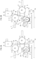
- each cooling roll T1, T2 is first retracted by the cylinder 5 as shown in FIG. 1A .
- the pre-elastomer M newly discharged and hanging down from the discharge port TO of the discharger T does not contact each cooling roll T1, T2.
- each cooling roll T1, T2 is provided movably to contact with and away from the hanging-down pre-elastomer M of FIG. 1A .
- each of the pass lines 1, 1A for the first and second sheets S1, S2 are formed by one or more first rolls 21, the bonding roll Ar, and the like for conveying the sheets S1, S2.
- a pass line 2 for the laminate W is formed by the bonding roll Ar, second rolls 22, and the like for conveying the laminate W.
- the film pass line 3 is formed by the first cooling roll T1 and the second cooling roll T2 for conveying the pre-elastomer M or elastomer film F and the bonding roll Ar and the like for bonding the elastomer film F to the both sheets S1, S2.
- the pass line 2 for the laminate W of FIG. 3B is formed so that the pair of sheet pass lines 1, 1A and the film pass line 3 join at the bonding roll Ar.
- the first cooling roll T1 is arranged to face one side surface of the pre-elastomer M hanging down from the discharge port TO.
- the second cooling roll T2 (pressing roll) is arranged to face the other side surface opposite to the one side surface.
- the resin in the molten state which becomes the pre-elastomer M of FIG. 1A , hangs down from the discharge port TO of the discharger T, and the film-like pre-elastomer M is continuously discharged.
- the pre-elastomer M hangs down on one flat plane along a vertical plane without contacting each roll T1, T2, Ar.
- the first sheet S1 is conveyed along the first pass line 1 for first sheet in a lateral or oblique lateral direction immediately below the discharge port TO.
- the tip part E of the pre-elastomer M discharged and hanging down from the discharge port TO is received with the sheet S1 as shown in FIG. 1B .
- the tip part E is overlapped on the first sheet S1 and the first sheet S1 and the pre-elastomer M in a mutually overlapping (doubled) state are conveyed along the first pass line 1 for first sheet as shown in FIG. 2A .
- the first sheet S1 and the pre-elastomer M in the mutually overlapping state are introduced along the outer peripheral surface of the bonding roll Ar (an example of a bonding part (joining part)) from the first pass line 1 for first sheet.
- the pre-elastomer M starts to be linearly conveyed from the discharge port TO to contact the outer peripheral surface of the bonding roll Ar as shown in FIG. 2B . Thereafter, as shown in FIG. 3A , the first cooling roll T1 and the second cooling roll T2 are moved toward the pre-elastomer M.
- the pre-elastomer M continuously discharged from the discharge port TO contacts the outer peripheral surfaces of the first cooling roll T1 and the second cooling roll T2, and the film pass line 3 in which the elastomer film F is sandwiched between the second cooling roll T2 and the nip roll Nr is formed (completed).
- a first cooling step is performed in which the pre-elastomer M is wound on the outer peripheral surface of the first cooling roll T1 to be cooled. If a manufacturing apparatus includes at least one cooling roll, a film pass line is formed when the pre-elastomer M contacts this cooling roll.
- each cooling roll is for cooling the molten resin or film and may internally include a flow passage for cooling a roll surface by the flow of a refrigerant.
- the nip roll Nr sandwiches the elastomer film F on a side further upstream than the bonding roll Ar.
- the elastomer film F before being bonded to the both sheets S1, S2 is stretched in the conveying direction because the conveying speed V of the elastomer film F on the bonding roll Ar is larger than the conveying speed Vs of the elastomer film F on the nip roll Nr. In this way, a pre-stress (tension) is applied to the elastomer film F.
- the horn H repeatedly applies ultrasonic vibration to the bonding roll Ar to bond the elastomer film F to the first and second sheets S1, S2 on the bonding roll Ar, whereby the laminate W is produced as shown in FIG. 3B .
- the both sheets S1, S2 and the elastomer film F are conveyed in an overlapping manner along the outer peripheral surface of the bonding roll Ar and the horn H applies ultrasonic vibration to the bonding roll Ar, whereby ultrasonic energy is applied to the both sheets S1, S2 and the elastic film F, and the nonwoven fabric sheets and the elastomer film are bonded and laminated.
- the bonding may be, for example, intermittently performed so that the laminate W alternately has stretch regions and bonded regions.
- the pre-elastomer M discharged from the discharge port TO of FIG. 1A has uneven quality in the initial production stage.
- the initially formed pre-elastomer M may be cut and removed, and then be discarded.
Landscapes
- Engineering & Computer Science (AREA)
- Mechanical Engineering (AREA)
- Physics & Mathematics (AREA)
- Thermal Sciences (AREA)
- Textile Engineering (AREA)
- Lining Or Joining Of Plastics Or The Like (AREA)
- Laminated Bodies (AREA)
- Extrusion Moulding Of Plastics Or The Like (AREA)
- Shaping Of Tube Ends By Bending Or Straightening (AREA)
Claims (11)
- Herstellungsverfahren zur Herstellung eines Laminats (W) durch Laminieren eines thermoplastischen Films (F) auf eine erste Folie (S1) und eine zweite Folie (S2) an einem Verbindungsteil nach einem Durchlauflinienbildungsprozess zur Bildung einer Durchlauflinie für ein foliengebildetes Folienrohmaterial (M), wobei das Folienrohmaterial (M) zu dem thermoplastischen Film (F) wird, wobei der Durchlauflinienbildungsprozess umfasst:einen Schritt des Herabhängens eines Harzes in einem geschmolzenen Zustand von einer Auslassöffnung (TO) einer Auslassvorrichtung (T), wobei das Harz das Folienrohmaterial (M) wird und der Schritt des Herabhängens das Folienrohmaterial (M) kontinuierlich auslässt;einen ersten Förderschritt des Förderns des ersten Bogens (S1) in einer seitlichen oder schrägen seitlichen Richtung entlang einer ersten Bogendurchlauflinie (1) unterhalb der Auslassöffnung (TO);einen Aufnahmeschritt zum Aufnehmen eines Spitzenteils (E) des Folienrohmaterials (M) mit dem ersten Blatt (S1) auf der ersten Blattdurchlauflinie (1), wobei das Spitzenteil (E) entladen wird und von der Entladeöffnung (TO) herabhängt;einen zweiten Förderschritt des Förderns des ersten Blattes (S1) und des Folienrohmaterials (M), nachdem das Spitzenteil (E) das erste Blatt (S1) auf der ersten Blattdurchlauflinie (1) überlappt, wobei der zweite Förderschritt das erste Blatt (S1) und das Folienrohmaterial (M) in einem sich gegenseitig überlappenden Zustand entlang der ersten Blattdurchlauflinie (1) fördert; undeinen Einführungsschritt des Einführens der ersten Folie (S1) und des Folienrohmaterials (M) in dem sich gegenseitig überlappenden Zustand zu dem Verbindungsteil von der ersten Foliendurchlauflinie (1), wobei die thermoplastische Folie (F) eine Elastomerfolie (F) ist und das Folienrohmaterial (M) ein foliengeformtes Vorelastomer (M) ist,wobei die erste Folie (S1) und die Elastomerfolie (F) in überlappender Weise entlang einer äußeren Umfangsfläche einer als Verbindungsteil dienenden Verbindungswalze (Ar) transportiert werden und ein Verbindungsschritt auf der Verbindungswalze (Ar) durchgeführt wird,die erste Bahn (S1) und die zweite Bahn (S2) aus Vliesstoff der Klebewalze (Ar) zugeführt werden,die erste Folie (S1) und die zweite Folie (S2) werden der Verbindungswalze (Ar) entlang der ersten (1) bzw. der zweiten (1A) Foliendurchlauflinie zugeführt,die Elastomerfolie (F) in die Verbindungswalze (Ar) eingeführt wird, während sie von dem Paar von Bögen (S1, S2) eingeschlossen wird, und das Paar von Bögen (S1, S2) und die Elastomerfolie (F) auf der Verbindungswalze (Ar) durch ein Ultraschallhorn (H) miteinander verbunden und laminiert werden, um das Laminat (W) herzustellen.
- Herstellungsverfahren nach Anspruch 1, wobei der Schritt des Verbindens die Elastomerfolie (F), die durch Verfestigung des Vorelastomers (M) erhalten wurde, mit der ersten Folie (S1) verbindet und die beiden Folien an der Verbindungsstelle miteinander laminiert werden, um das Laminat (W) herzustellen.
- Herstellungsverfahren nach Anspruch 1, umfassend einen ersten Kühlschritt des Abkühlens des foliengebildeten Vorelastomers (M), das von der Auslassöffnung (TO) herabhängt, durch Aufwickeln des Vorelastomers (M) auf eine äußere Umfangsfläche einer ersten Kühlwalze (T1) nach dem Einführungsschritt.
- Herstellungsverfahren nach Anspruch 3, wobei:die erste Kühlwalze (T1) beweglich vorgesehen ist und in der Lage ist, das foliengebildete Vorelastomer (M), das im Schritt des Herunterhängens herunterhängt, zu berühren und sich von ihm wegzubewegen, undder erste Kühlschritt gestartet wird, um das Vorelastomer (M) zu kühlen, nachdem der Spitzenteil (E) des Vorelastomers (M) und die erste Folie (S1) auf die Klebewalze (Ar) gewickelt sind.
- Herstellungsverfahren nach Anspruch 4, wobei:die erste Kühlwalze (T1) so angeordnet ist, dass sie einer Seitenfläche des Vorelastomers (M) zugewandt ist, die in dem Schritt des Herunterhängens von der Auslassöffnung (TO) herabhängt,eine Presswalze so angeordnet ist, dass sie einer anderen Seitenfläche gegenüberliegt, die der einen Seitenfläche des Vorelastomers (M) in dem Schritt des Herunterhängens gegenüberliegt,das Herstellungsverfahren ferner einen Schritt des Bewegens der Presswalze in einer Richtung umfasst, die eine Aufhängungsrichtung des Vorelastomers (M) kreuzt, um einen Kontaktabstand des Vorelastomers (M) mit der ersten Kühlwalze (T1) zu vergrößern,vorzugsweise ist die Presswalze eine zweite Kühlwalze (T2), unddas Herstellungsverfahren einen zweiten Kühlschritt des weiteren Kühlens des Vorelastomers (M), das durch die erste Kühlwalze (T1) gekühlt worden ist, durch die zweite Kühlwalze (T2) umfasst.
- Herstellungsverfahren nach Anspruch 4, wobei:eine Anpresswalze (Nr) zum Einklemmen der Elastomerfolie (F) weiter stromaufwärts als die Klebewalze (Ar) vorgesehen ist, unddas Herstellungsverfahren einen Streckschritt des Streckens der Elastomerfolie (F) vor dem Verbinden mit der ersten Folie (S1) in einer Transportrichtung durch eine Transportgeschwindigkeit (V) der Elastomerfolie (F) auf der Verbindungswalze (Ar), die größer ist als eine Transportgeschwindigkeit (Vs) der Elastomerfolie (F) auf der Quetschwalze (Nr), umfasst, wobei der Streckschritt durchgeführt wird, nachdem der erste Kühlschritt begonnen wurde.
- Herstellungsvorrichtung zur Herstellung eines Laminats (W) durch Laminieren eines thermoplastischen Films (F) auf eine erste Folie (S1) und eine zweite Folie (S2) an einem Verbindungsteil nach einem Durchlauflinienbildungsprozess zur Bildung einer Durchlauflinie für ein foliengebildetes Folienrohmaterial (M), wobei das Folienrohmaterial (M) zu dem thermoplastischen Film (F) wird, wobei die Herstellungsvorrichtung umfasst:eine Austragsvorrichtung (T), um zu bewirken, dass ein Harz in einem geschmolzenen Zustand von einer Austragsöffnung (TO) herunterhängt, wobei das Harz das Folienrohmaterial (M) wird, und die Austragsvorrichtung (T) das Folienrohmaterial (M) kontinuierlich austrägt;eine erste Bogendurchlauflinie (1) zum Fördern des ersten Bogens (S1) in einer seitlichen oder schrägen seitlichen Richtung unterhalb der Abgabeöffnung (TO), wobei die erste Bogendurchlauflinie (1) einen Kopfteil (E) des Folienrohmaterials (M) mit dem ersten Bogen (S1) aufnimmt, die erste Blattdurchlaufbahn (1) einen Kopfteil (E) des Folienrohmaterials (M) mit dem ersten Blatt (S1) aufnimmt, wobei der Kopfteil (E) ausgestoßen wird und von der Ausstoßöffnung (TO) herabhängt, und die erste Blattdurchlaufbahn (1) das erste Blatt (S1) und das Folienrohmaterial (M) in einem sich gegenseitig überlappenden Zustand befördert, nachdem der Kopfteil (E) das erste Blatt (S1) überlappt hat; unddas Verbindungsteil so konfiguriert ist, dass das erste Blatt (S1) und das Folienrohmaterial (M) in dem sich gegenseitig überlappenden Zustand von der ersten Blattdurchlauflinie (1) in das Verbindungsteil eingeführt werden,wobei eine Verbindungswalze (Ar) als das Verbindungsteil dient, wobei die Verbindungswalze (Ar) so konfiguriert ist, dass das erste Blatt (S1) und die Folie (F) in einer überlappenden Weise entlang einer äußeren Umfangsfläche der Verbindungswalze (Ar) befördert werden,die erste Folie (S1) und die zweite Folie (S2) aus Vliesstoff der Verbindungswalze (Ar) zugeführt werden, das erste Blatt (S1) und das zweite Blatt (S2) werden entlang der ersten Blattdurchlauflinie (1) bzw. einer zweiten Blattdurchlauflinie (1A) der Klebewalze (Ar) zugeführt,die Folie (F) in die Verbindungswalze (Ar) eingeführt wird, während sie von dem Paar von Bögen (S1, S2) eingeschlossen wird, und das Paar von Bögen (S1, S2) und die Folie (F) auf der Verbindungswalze (Ar) durch ein Ultraschallhorn (H) miteinander verbunden und laminiert werden, um das Laminat (W) herzustellen,wobei die thermoplastische Folie (F) eine Elastomerfolie (F) und das Folienrohmaterial (M) ein foliengeformtes Vorelastomer (M) ist.
- Herstellungsvorrichtung nach Anspruch 7, wobei
das Laminat (W) an dem Verbindungsteil durch Laminieren des Elastomerfilms (F), der durch Verfestigen des Vorelastomers (M) erhalten wurde, auf die erste Platte (S1) und durch Verbinden des Elastomerfilms (F) mit der ersten Platte (S1) hergestellt wird. - Herstellungsvorrichtung nach Anspruch 7, umfassend eine erste Kühlwalze (T1) zum Kühlen des foliengeformten Vorelastomers (M), wobei das Vorelastomer (M) von der Abgabeöffnung (TO) herabhängt und auf eine äußere Umfangsfläche der ersten Kühlwalze (T1) gewickelt ist,
wobei die erste Kühlwalze (T1) vorzugsweise beweglich vorgesehen ist und in der Lage ist, das foliengebildete Vorelastomer (M), das von der Auslassöffnung (TO) herabhängt, zu berühren und sich von ihm wegzubewegen. - Die Herstellungsvorrichtung nach Anspruch 9, wobei:die erste Kühlwalze (T1) so angeordnet ist, dass sie einer Seitenfläche des Vorelastomers (M) zugewandt ist, die von der Auslassöffnung (TO) herabhängt, unddie Herstellungsvorrichtung ferner eine Presswalze enthält, die so angeordnet ist, dass sie einer anderen Seitenfläche gegenüber der einen Seitenfläche des Vorelastomers (M) zugewandt ist, und die so konfiguriert ist, dass sie sich in einer Richtung bewegt, die eine Hängerichtung des Vorelastomers (M) schneidet, um einen Kontaktabstand des Vorelastomers (M) mit der ersten Kühlwalze (T1) zu vergrößern, wobei die Presswalze vorzugsweise eine zweite Kühlwalze (T2) zum weiteren Kühlen des Vorelastomers (M) ist, das durch die erste Kühlwalze (T1) gekühlt worden ist.
- Herstellungsvorrichtung nach Anspruch 10, wobei:eine Anpresswalze (Nr) zum Einlegen der Elastomerfolie (F) weiter stromaufwärts als die Verbindungswalze (Ar) vorgesehen ist, undeine Transportgeschwindigkeit (V) der Elastomerfolie (F) auf der Verbindungswalze (Ar) so eingestellt ist, dass sie größer ist als eine Transportgeschwindigkeit Vs der Elastomerfolie (F) auf der Anpresswalze (Nr), nachdem der erste Kühlschritt begonnen hat, so dass die Elastomerfolie (F) vor dem Verbinden mit der ersten Platte (S1) in einer Transportrichtung gestreckt wird.
Applications Claiming Priority (2)
| Application Number | Priority Date | Filing Date | Title |
|---|---|---|---|
| JP2018202621 | 2018-10-29 | ||
| PCT/JP2019/042209 WO2020090753A1 (ja) | 2018-10-29 | 2019-10-28 | 積層体の製造方法および製造装置 |
Publications (4)
| Publication Number | Publication Date |
|---|---|
| EP3875243A1 EP3875243A1 (de) | 2021-09-08 |
| EP3875243A4 EP3875243A4 (de) | 2021-12-22 |
| EP3875243B1 true EP3875243B1 (de) | 2024-07-24 |
| EP3875243C0 EP3875243C0 (de) | 2024-07-24 |
Family
ID=70462367
Family Applications (1)
| Application Number | Title | Priority Date | Filing Date |
|---|---|---|---|
| EP19878886.1A Active EP3875243B1 (de) | 2018-10-29 | 2019-10-28 | Laminatherstellungsverfahren und herstellungsvorrichtung |
Country Status (5)
| Country | Link |
|---|---|
| US (1) | US11597195B2 (de) |
| EP (1) | EP3875243B1 (de) |
| JP (1) | JP7203118B2 (de) |
| CN (1) | CN112839792B (de) |
| WO (1) | WO2020090753A1 (de) |
Families Citing this family (1)
| Publication number | Priority date | Publication date | Assignee | Title |
|---|---|---|---|---|
| WO2023127706A1 (ja) | 2021-12-28 | 2023-07-06 | 株式会社瑞光 | 伸縮シートの貯留方法及び装置 |
Family Cites Families (14)
| Publication number | Priority date | Publication date | Assignee | Title |
|---|---|---|---|---|
| FI64078C (fi) * | 1979-03-29 | 1983-10-10 | Lohjan Paperi Oy | Foerfarande foer framstaellning av en haeftplastprodukt |
| JP3481766B2 (ja) | 1996-03-29 | 2003-12-22 | 株式会社クラレ | 積層体およびその製造方法 |
| JP3054930B2 (ja) | 1996-07-17 | 2000-06-19 | 花王株式会社 | 積層シートおよびその製造方法 |
| JP3176871B2 (ja) * | 1996-07-18 | 2001-06-18 | 花王株式会社 | 使い捨ておむつ |
| US6238767B1 (en) * | 1997-09-15 | 2001-05-29 | Kimberly-Clark Worldwide, Inc. | Laminate having improved barrier properties |
| JP2001032160A (ja) * | 1999-05-17 | 2001-02-06 | Nippon Petrochem Co Ltd | 伸縮性を有する複合シート、該複合シートの製造方法、及び前記複合シートの製造装置 |
| AU2004312045B2 (en) * | 2003-12-31 | 2010-05-27 | Kimberly-Clark Worldwide, Inc. | Single side facing stretch bonded laminates, and method of making same |
| US9457547B2 (en) * | 2007-11-07 | 2016-10-04 | Magnum Magnetics Corporation | Extrudable adherable material systems |
| US20100168704A1 (en) * | 2008-12-31 | 2010-07-01 | Thomas Oomman P | Method of forming an elastic laminate including a cross-linked elastic film |
| KR101222548B1 (ko) * | 2010-10-07 | 2013-01-16 | 주식회사 인트로팩 | 단사가 접착된 시트의 제조 장치 및 방법 |
| JP2013193343A (ja) * | 2012-03-21 | 2013-09-30 | Sumitomo Chemical Co Ltd | 積層体の製造方法 |
| FR2993543B1 (fr) * | 2012-07-19 | 2014-08-15 | Bostik Sa | Film multicouche pour emballage flexible |
| US20150299947A1 (en) * | 2014-04-16 | 2015-10-22 | Shaw Industries Group, Inc. | Carpet, carpet backings and methods |
| WO2018062028A1 (ja) * | 2016-09-30 | 2018-04-05 | 富士フイルム株式会社 | 熱可塑性樹脂フィルムの製造方法 |
-
2019
- 2019-10-28 EP EP19878886.1A patent/EP3875243B1/de active Active
- 2019-10-28 WO PCT/JP2019/042209 patent/WO2020090753A1/ja not_active Ceased
- 2019-10-28 JP JP2020553901A patent/JP7203118B2/ja active Active
- 2019-10-28 US US17/282,760 patent/US11597195B2/en active Active
- 2019-10-28 CN CN201980067401.XA patent/CN112839792B/zh active Active
Also Published As
| Publication number | Publication date |
|---|---|
| WO2020090753A1 (ja) | 2020-05-07 |
| CN112839792A (zh) | 2021-05-25 |
| JP7203118B2 (ja) | 2023-01-12 |
| EP3875243A4 (de) | 2021-12-22 |
| EP3875243C0 (de) | 2024-07-24 |
| CN112839792B (zh) | 2023-05-12 |
| US20220001659A1 (en) | 2022-01-06 |
| JPWO2020090753A1 (ja) | 2021-09-24 |
| EP3875243A1 (de) | 2021-09-08 |
| US11597195B2 (en) | 2023-03-07 |
Similar Documents
| Publication | Publication Date | Title |
|---|---|---|
| JP7290579B2 (ja) | 伸縮複合シートの製造方法、伸縮複合シート及び該伸縮複合シートを用いた使い捨て着用物品 | |
| US7704901B2 (en) | Method for producing a laminate material web having elastic and non-elastic regions | |
| CN107753184B (zh) | 伸缩片的制造方法 | |
| US20200361158A1 (en) | Apparatus for manufacturing wearing article and method of manufacturing same | |
| CN111886127B (zh) | 伸缩片材、使用该伸缩片材的一次性穿戴物品及其制造方法 | |
| EP3875243B1 (de) | Laminatherstellungsverfahren und herstellungsvorrichtung | |
| US11850783B2 (en) | Manufacturing method and manufacturing apparatus for laminate | |
| JP2002069816A (ja) | 弾性伸縮性を有する複合シートの製造方法 | |
| US11759991B2 (en) | Production method and production apparatus for thermoplastic film | |
| CN111867535B (zh) | 一种伸缩复合片制造方法及制造装置 | |
| EP2719805B1 (de) | Verpackungsmaterial | |
| WO2019151064A1 (ja) | 弾性シートの製造方法及び製造装置、伸縮複合シートの製造方法及び製造装置、並びに伸縮複合シート | |
| JPWO2020090753A5 (de) | ||
| CN120957692A (zh) | 一种一次性可穿戴物品的制造方法 |
Legal Events
| Date | Code | Title | Description |
|---|---|---|---|
| STAA | Information on the status of an ep patent application or granted ep patent |
Free format text: STATUS: THE INTERNATIONAL PUBLICATION HAS BEEN MADE |
|
| PUAI | Public reference made under article 153(3) epc to a published international application that has entered the european phase |
Free format text: ORIGINAL CODE: 0009012 |
|
| STAA | Information on the status of an ep patent application or granted ep patent |
Free format text: STATUS: REQUEST FOR EXAMINATION WAS MADE |
|
| 17P | Request for examination filed |
Effective date: 20210326 |
|
| AK | Designated contracting states |
Kind code of ref document: A1 Designated state(s): AL AT BE BG CH CY CZ DE DK EE ES FI FR GB GR HR HU IE IS IT LI LT LU LV MC MK MT NL NO PL PT RO RS SE SI SK SM TR |
|
| REG | Reference to a national code |
Ipc: B32B0041000000 Ref country code: DE Ref legal event code: R079 Ref document number: 602019055900 Country of ref document: DE Free format text: PREVIOUS MAIN CLASS: B29C0048080000 |
|
| A4 | Supplementary search report drawn up and despatched |
Effective date: 20211122 |
|
| RIC1 | Information provided on ipc code assigned before grant |
Ipc: B32B 37/08 20060101ALN20211116BHEP Ipc: B29C 48/885 20190101ALI20211116BHEP Ipc: B29C 48/15 20190101ALI20211116BHEP Ipc: B29C 48/08 20190101ALI20211116BHEP Ipc: B32B 37/20 20060101ALI20211116BHEP Ipc: B32B 41/00 20060101AFI20211116BHEP |
|
| DAV | Request for validation of the european patent (deleted) | ||
| DAX | Request for extension of the european patent (deleted) | ||
| STAA | Information on the status of an ep patent application or granted ep patent |
Free format text: STATUS: EXAMINATION IS IN PROGRESS |
|
| 17Q | First examination report despatched |
Effective date: 20230214 |
|
| GRAP | Despatch of communication of intention to grant a patent |
Free format text: ORIGINAL CODE: EPIDOSNIGR1 |
|
| STAA | Information on the status of an ep patent application or granted ep patent |
Free format text: STATUS: GRANT OF PATENT IS INTENDED |
|
| RIC1 | Information provided on ipc code assigned before grant |
Ipc: B32B 37/08 20060101ALN20240123BHEP Ipc: B29C 48/885 20190101ALI20240123BHEP Ipc: B29C 48/15 20190101ALI20240123BHEP Ipc: B29C 48/08 20190101ALI20240123BHEP Ipc: B32B 37/20 20060101ALI20240123BHEP Ipc: B32B 41/00 20060101AFI20240123BHEP |
|
| INTG | Intention to grant announced |
Effective date: 20240214 |
|
| GRAS | Grant fee paid |
Free format text: ORIGINAL CODE: EPIDOSNIGR3 |
|
| GRAA | (expected) grant |
Free format text: ORIGINAL CODE: 0009210 |
|
| STAA | Information on the status of an ep patent application or granted ep patent |
Free format text: STATUS: THE PATENT HAS BEEN GRANTED |
|
| AK | Designated contracting states |
Kind code of ref document: B1 Designated state(s): AL AT BE BG CH CY CZ DE DK EE ES FI FR GB GR HR HU IE IS IT LI LT LU LV MC MK MT NL NO PL PT RO RS SE SI SK SM TR |
|
| REG | Reference to a national code |
Ref country code: GB Ref legal event code: FG4D |
|
| REG | Reference to a national code |
Ref country code: CH Ref legal event code: EP |
|
| REG | Reference to a national code |
Ref country code: DE Ref legal event code: R096 Ref document number: 602019055900 Country of ref document: DE |
|
| REG | Reference to a national code |
Ref country code: IE Ref legal event code: FG4D |
|
| U01 | Request for unitary effect filed |
Effective date: 20240802 |
|
| U07 | Unitary effect registered |
Designated state(s): AT BE BG DE DK EE FI FR IT LT LU LV MT NL PT SE SI Effective date: 20240820 |
|
| U20 | Renewal fee for the european patent with unitary effect paid |
Year of fee payment: 6 Effective date: 20241025 |
|
| PG25 | Lapsed in a contracting state [announced via postgrant information from national office to epo] |
Ref country code: NO Free format text: LAPSE BECAUSE OF FAILURE TO SUBMIT A TRANSLATION OF THE DESCRIPTION OR TO PAY THE FEE WITHIN THE PRESCRIBED TIME-LIMIT Effective date: 20241024 |
|
| PG25 | Lapsed in a contracting state [announced via postgrant information from national office to epo] |
Ref country code: GR Free format text: LAPSE BECAUSE OF FAILURE TO SUBMIT A TRANSLATION OF THE DESCRIPTION OR TO PAY THE FEE WITHIN THE PRESCRIBED TIME-LIMIT Effective date: 20241025 Ref country code: PL Free format text: LAPSE BECAUSE OF FAILURE TO SUBMIT A TRANSLATION OF THE DESCRIPTION OR TO PAY THE FEE WITHIN THE PRESCRIBED TIME-LIMIT Effective date: 20240724 |
|
| PG25 | Lapsed in a contracting state [announced via postgrant information from national office to epo] |
Ref country code: IS Free format text: LAPSE BECAUSE OF FAILURE TO SUBMIT A TRANSLATION OF THE DESCRIPTION OR TO PAY THE FEE WITHIN THE PRESCRIBED TIME-LIMIT Effective date: 20241124 |
|
| PG25 | Lapsed in a contracting state [announced via postgrant information from national office to epo] |
Ref country code: HR Free format text: LAPSE BECAUSE OF FAILURE TO SUBMIT A TRANSLATION OF THE DESCRIPTION OR TO PAY THE FEE WITHIN THE PRESCRIBED TIME-LIMIT Effective date: 20240724 |
|
| PGFP | Annual fee paid to national office [announced via postgrant information from national office to epo] |
Ref country code: CZ Payment date: 20241021 Year of fee payment: 6 |
|
| PG25 | Lapsed in a contracting state [announced via postgrant information from national office to epo] |
Ref country code: RS Free format text: LAPSE BECAUSE OF FAILURE TO SUBMIT A TRANSLATION OF THE DESCRIPTION OR TO PAY THE FEE WITHIN THE PRESCRIBED TIME-LIMIT Effective date: 20241024 Ref country code: ES Free format text: LAPSE BECAUSE OF FAILURE TO SUBMIT A TRANSLATION OF THE DESCRIPTION OR TO PAY THE FEE WITHIN THE PRESCRIBED TIME-LIMIT Effective date: 20240724 |
|
| PG25 | Lapsed in a contracting state [announced via postgrant information from national office to epo] |
Ref country code: RS Free format text: LAPSE BECAUSE OF FAILURE TO SUBMIT A TRANSLATION OF THE DESCRIPTION OR TO PAY THE FEE WITHIN THE PRESCRIBED TIME-LIMIT Effective date: 20241024 Ref country code: PL Free format text: LAPSE BECAUSE OF FAILURE TO SUBMIT A TRANSLATION OF THE DESCRIPTION OR TO PAY THE FEE WITHIN THE PRESCRIBED TIME-LIMIT Effective date: 20240724 Ref country code: NO Free format text: LAPSE BECAUSE OF FAILURE TO SUBMIT A TRANSLATION OF THE DESCRIPTION OR TO PAY THE FEE WITHIN THE PRESCRIBED TIME-LIMIT Effective date: 20241024 Ref country code: IS Free format text: LAPSE BECAUSE OF FAILURE TO SUBMIT A TRANSLATION OF THE DESCRIPTION OR TO PAY THE FEE WITHIN THE PRESCRIBED TIME-LIMIT Effective date: 20241124 Ref country code: HR Free format text: LAPSE BECAUSE OF FAILURE TO SUBMIT A TRANSLATION OF THE DESCRIPTION OR TO PAY THE FEE WITHIN THE PRESCRIBED TIME-LIMIT Effective date: 20240724 Ref country code: GR Free format text: LAPSE BECAUSE OF FAILURE TO SUBMIT A TRANSLATION OF THE DESCRIPTION OR TO PAY THE FEE WITHIN THE PRESCRIBED TIME-LIMIT Effective date: 20241025 Ref country code: ES Free format text: LAPSE BECAUSE OF FAILURE TO SUBMIT A TRANSLATION OF THE DESCRIPTION OR TO PAY THE FEE WITHIN THE PRESCRIBED TIME-LIMIT Effective date: 20240724 |
|
| PGFP | Annual fee paid to national office [announced via postgrant information from national office to epo] |
Ref country code: TR Payment date: 20241021 Year of fee payment: 6 |
|
| PG25 | Lapsed in a contracting state [announced via postgrant information from national office to epo] |
Ref country code: RO Free format text: LAPSE BECAUSE OF FAILURE TO SUBMIT A TRANSLATION OF THE DESCRIPTION OR TO PAY THE FEE WITHIN THE PRESCRIBED TIME-LIMIT Effective date: 20240724 Ref country code: SM Free format text: LAPSE BECAUSE OF FAILURE TO SUBMIT A TRANSLATION OF THE DESCRIPTION OR TO PAY THE FEE WITHIN THE PRESCRIBED TIME-LIMIT Effective date: 20240724 |
|
| PG25 | Lapsed in a contracting state [announced via postgrant information from national office to epo] |
Ref country code: SK Free format text: LAPSE BECAUSE OF FAILURE TO SUBMIT A TRANSLATION OF THE DESCRIPTION OR TO PAY THE FEE WITHIN THE PRESCRIBED TIME-LIMIT Effective date: 20240724 |
|
| PLBE | No opposition filed within time limit |
Free format text: ORIGINAL CODE: 0009261 |
|
| STAA | Information on the status of an ep patent application or granted ep patent |
Free format text: STATUS: NO OPPOSITION FILED WITHIN TIME LIMIT |
|
| REG | Reference to a national code |
Ref country code: CH Ref legal event code: PL |
|
| GBPC | Gb: european patent ceased through non-payment of renewal fee |
Effective date: 20241028 |
|
| 26N | No opposition filed |
Effective date: 20250425 |
|
| PG25 | Lapsed in a contracting state [announced via postgrant information from national office to epo] |
Ref country code: MC Free format text: LAPSE BECAUSE OF FAILURE TO SUBMIT A TRANSLATION OF THE DESCRIPTION OR TO PAY THE FEE WITHIN THE PRESCRIBED TIME-LIMIT Effective date: 20240724 |
|
| PG25 | Lapsed in a contracting state [announced via postgrant information from national office to epo] |
Ref country code: GB Free format text: LAPSE BECAUSE OF NON-PAYMENT OF DUE FEES Effective date: 20241028 |
|
| PG25 | Lapsed in a contracting state [announced via postgrant information from national office to epo] |
Ref country code: CH Free format text: LAPSE BECAUSE OF NON-PAYMENT OF DUE FEES Effective date: 20241031 |
|
| PG25 | Lapsed in a contracting state [announced via postgrant information from national office to epo] |
Ref country code: IE Free format text: LAPSE BECAUSE OF NON-PAYMENT OF DUE FEES Effective date: 20241028 |
|
| PG25 | Lapsed in a contracting state [announced via postgrant information from national office to epo] |
Ref country code: HU Free format text: LAPSE BECAUSE OF FAILURE TO SUBMIT A TRANSLATION OF THE DESCRIPTION OR TO PAY THE FEE WITHIN THE PRESCRIBED TIME-LIMIT; INVALID AB INITIO Effective date: 20191028 |