EP3874302B1 - Progressive asphärische korrektur für optisches system mit elektrisch durchstimmbarer linse - Google Patents
Progressive asphärische korrektur für optisches system mit elektrisch durchstimmbarer linse Download PDFInfo
- Publication number
- EP3874302B1 EP3874302B1 EP19805077.5A EP19805077A EP3874302B1 EP 3874302 B1 EP3874302 B1 EP 3874302B1 EP 19805077 A EP19805077 A EP 19805077A EP 3874302 B1 EP3874302 B1 EP 3874302B1
- Authority
- EP
- European Patent Office
- Prior art keywords
- lens
- aspherical
- etl
- correction lens
- spherical aberration
- Prior art date
- Legal status (The legal status is an assumption and is not a legal conclusion. Google has not performed a legal analysis and makes no representation as to the accuracy of the status listed.)
- Active
Links
Images



Classifications
-
- G—PHYSICS
- G02—OPTICS
- G02B—OPTICAL ELEMENTS, SYSTEMS OR APPARATUS
- G02B27/00—Optical systems or apparatus not provided for by any of the groups G02B1/00 - G02B26/00, G02B30/00
- G02B27/0025—Optical systems or apparatus not provided for by any of the groups G02B1/00 - G02B26/00, G02B30/00 for optical correction, e.g. distorsion, aberration
-
- G—PHYSICS
- G02—OPTICS
- G02B—OPTICAL ELEMENTS, SYSTEMS OR APPARATUS
- G02B3/00—Simple or compound lenses
- G02B3/02—Simple or compound lenses with non-spherical faces
-
- G—PHYSICS
- G02—OPTICS
- G02B—OPTICAL ELEMENTS, SYSTEMS OR APPARATUS
- G02B21/00—Microscopes
- G02B21/0004—Microscopes specially adapted for specific applications
- G02B21/002—Scanning microscopes
- G02B21/0024—Confocal scanning microscopes (CSOMs) or confocal "macroscopes"; Accessories which are not restricted to use with CSOMs, e.g. sample holders
-
- G—PHYSICS
- G02—OPTICS
- G02B—OPTICAL ELEMENTS, SYSTEMS OR APPARATUS
- G02B21/00—Microscopes
- G02B21/0004—Microscopes specially adapted for specific applications
- G02B21/002—Scanning microscopes
- G02B21/0024—Confocal scanning microscopes (CSOMs) or confocal "macroscopes"; Accessories which are not restricted to use with CSOMs, e.g. sample holders
- G02B21/0052—Optical details of the image generation
- G02B21/006—Optical details of the image generation focusing arrangements; selection of the plane to be imaged
-
- G—PHYSICS
- G02—OPTICS
- G02B—OPTICAL ELEMENTS, SYSTEMS OR APPARATUS
- G02B21/00—Microscopes
- G02B21/0004—Microscopes specially adapted for specific applications
- G02B21/002—Scanning microscopes
- G02B21/0024—Confocal scanning microscopes (CSOMs) or confocal "macroscopes"; Accessories which are not restricted to use with CSOMs, e.g. sample holders
- G02B21/0052—Optical details of the image generation
- G02B21/0076—Optical details of the image generation arrangements using fluorescence or luminescence
-
- G—PHYSICS
- G02—OPTICS
- G02B—OPTICAL ELEMENTS, SYSTEMS OR APPARATUS
- G02B21/00—Microscopes
- G02B21/24—Base structure
- G02B21/241—Devices for focusing
-
- G—PHYSICS
- G02—OPTICS
- G02B—OPTICAL ELEMENTS, SYSTEMS OR APPARATUS
- G02B26/00—Optical devices or arrangements for the control of light using movable or deformable optical elements
- G02B26/004—Optical devices or arrangements for the control of light using movable or deformable optical elements based on a displacement or a deformation of a fluid
-
- G—PHYSICS
- G02—OPTICS
- G02B—OPTICAL ELEMENTS, SYSTEMS OR APPARATUS
- G02B3/00—Simple or compound lenses
- G02B3/12—Fluid-filled or evacuated lenses
- G02B3/14—Fluid-filled or evacuated lenses of variable focal length
-
- G—PHYSICS
- G02—OPTICS
- G02B—OPTICAL ELEMENTS, SYSTEMS OR APPARATUS
- G02B2207/00—Coding scheme for general features or characteristics of optical elements and systems of subclass G02B, but not including elements and systems which would be classified in G02B6/00 and subgroups
- G02B2207/115—Electrowetting
Definitions
- Fig. 1 which is part of the prior art, depicts the basic design of a style of electrically tunable lenses made by Optotune. As shown in Fig. 1 , the lens is fabricated from a flexible film or membrane enclosing an optical fluid. The curvature of the lens is adjusted by applying an electric current to a voice coil or bobbin that surrounds perimeter of the lens. The focal length of the lens can thus be changed very quickly (within milliseconds) by means of mated controller (also available commercially) is tuned to a desired value within very few milliseconds.
- mated controller also available commercially
- ETLs are desirable because a change in the radius of only a few micrometers in the ETL can have the same optical effect as moving the entire lens several centimeters. This allows for compact optical device design, while still maintaining broad functionality and range of operation.
- electrically tunable lens yield optical systems that are more compact, oftentimes require fewer total lenses, and less translational movement of the lenses. This reduces the need for high-precision mechanical actuators to physically re-position lenses. Less potential movement of the lenses within the optical path leads to more robust designs.
- ETLs have an increasing spherical aberration component that is proportional with increasing power or curvature (i . e ., decreasing focal length) of the ETL.
- the increased spherical aberration of the ETL degrades the axial point spread function (PSF) at the sample plane when the ETL is driven toward the short end of its focal length range. This, in turn, blurs the ultimate image that can be generated with the optical device.
- PSF point spread function
- US2010/231783 discloses an optical system including a first deformable lens having a membrane with a deformable portion.
- a sensor is configured to receive the light focused by the first deformable lens.
- An optical path extends through the first deformable lens and to the sensor.
- the first deformable lens is tuned according to an applied electrical signal in order to directly focus light traversing the optical path onto the sensor.
- a first volume of a first optical media and a second volume of a second optical media are defined at least in part by the deformable portion of the membrane.
- the first volume and the second volume are completely enclosed by the housing.
- the first volume and the second volume remain substantially constant for all configurations of the first deformable lens.
- the optical system may comprise corrective lenses having an aspherical surface in order to correct for spherical aberration.
- US2008/247019 discloses a switchable optical unit, capable of controlling a beam of radiation passing through an optically active portion of the unit, comprises a fluid chamber including an electrically conductive liquid, which chamber comprises at least one first electrode fixed to the chamber inner walls at the position of the optically active portion and second electrode means fixed to inner walls of the chamber outside the optically active portion and a third electrode connected to the conductive liquid.
- a voltage By applying a voltage to the at least one first electrode and the second electrode means, respectively the conductive liquid can be moved in and out the optically active portion so that the unit is switched between a least two discrete states.
- Refractive surfaces of the switchable optical unit may be aspheric in order to correct for spherical aberrations.
- an optical device according to claim 1 and a method to correct spherical aberration in an optical path caused by an electrically tunable lens according to claim 6.
- an optical device comprising an electrically tunable lens (ETL) disposed within an optical path in working relationship with an aspherical correction lens.
- ETL electrically tunable lens
- the aspherical correction lens is disposed within the same optical path as the ETL and is dimensioned and configured to reduce spherical aberration in the light beam exiting the ETL.
- the aspherical surface (or surfaces) of the aspherical correction lens are shaped in such a fashion as to yield progressive spherical aberration reduction throughout the entire focal length range of the ETL, but especially when the ETL is at or near the lower limit of its focal length ( i . e ., when the ETL is at or near its maximum magnification).
- Fig. 2 The optical device and corresponding method and principle of operation are illustrated in Fig. 2 .
- the upper and lower panels show the same optical path that starts on the left with an ETL.
- the optical path itself is shown within the context of an otherwise conventional confocal microscope.
- the ETL in the top panel is shown at minimum power; while the ETL in the bottom panel is shown at maximum power.
- Optical relay 1 in both panels illustrates the focus shift that is associated with the change in focal length of the ETL.
- an aspherical correction lens is disposed within the light path.
- the light beam diameter passing through the aspherical correction lens is relatively small when the ETL is at its lowest magnification.
- the beam diameter passing through the aspherical correction lens is much larger.
- the asphericity of aspherical correction lens is progressive and is matched the spherical aberration component of its associated ETL.
- the spherical aberration component of the ETL increases, so does the beam diameter passing through the aspherical correction lens, and so too does the correction applied by the asphericity of the correction lens. That is, the correction applied by the asphericity of the aspherical correction lens is larger the farther the distance the beam is from the optical axis of the lens.
- Fig. 2 The remainder of Fig. 2 is convention.
- the light beam, with its spherical aberration reduced after exiting the correction lens, passes through optical relay #2, the second conjugate pupil plane, the tube lens, objective lens, and is focused onto the sample.
- the focal length of the ETL is then altered to adjust the point of focus in the z-plane within the sample plane.
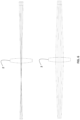
- Figs. 3A , 3B , and 3C show the problem at hand in isolation, with respect to the spherical aberration and degraded PSF of the ETL at short focal lengths.
- the top panel shows the condition of the ETL at low current / low magnification / long focal length.
- the bottom panel in each of Figs. 3A , 3B , and 3C shows the condition of the ETL at high current / high magnification / short focal length.
- Fig. 3A is a simple schematic ray diagram of a light beam exiting the ETL and to a focal point.
- the top panel in Fig. 3A shows the ETL at low current / low magnification / long focal length; the bottom panel in Fig. 3A shows the ETL at high current / high magnification / short focal length.
- Fig. 3B illustrates the impact of decreasing the focal length on a typical commercial ETL on the spherical aberration of the lens.
- the two upper plots in Fig. 3B record the spherical aberration of the ETL at low magnification / long focal length.
- the aberration here is small and generally acceptable.
- the spherical aberration is small enough that it does not have a significant adverse impact on the axial PSF.
- the two lower plots in Fig. 3B record the spherical aberration of the ETL at high magnification / short focal length.
- the spherical aberration here is large, significant, and unacceptable.
- the spherical aberration significantly degrades axial PSF and thus degrades the clarity of the images that can be generated at high magnification.
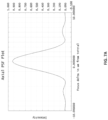
- the axial PSF for the ETL shown in Fig. 1 is presented in Fig. 3C at low magnification (top panel) and high magnification (bottom panel).
- the Airy function in the top panel (low magnification) is smooth, symmetrical, and well-focused.
- the Airy function in the bottom panel (high magnification) is flattened and "smeared.” As a result, images gathered at high magnification using this ETL are blurred.
- Fig. 4 to address the changing spherical aberration component of an ETL, the present method uses an aspherical lens 2, whose asphericity increases progressively with increased distance from the optical axis of the lens 2.
- Fig. 2 shows a series of ray tracings with the ETL going from low magnification / long focal length at the top, to high magnification / short focal length at the bottom. The downward pointing arrows show the focal point as magnification of the ETL increases.
- the beam diameter passing through aspherical lens 2 increases greatly as the ETL is canned from lowest power and smallest spherical aberration (top panel) to highest power and highest spherical aberration (bottom panel).
- the progressive asphericity of lens 2 is dimensioned and configured to correct the spherical aberration when a beam of relatively larger diameter passes through it.
- aspherical lens 2 yields a focused beam with minimal spherical aberration and a high-quality axial PSF. That is, the aberrant rays of the optical path are distributed with an increasing severity that is proportional to their increasing distance from the optical axis.
- progressive aspherical lens 2 the most aberrant rays ( i . e ., those furthest from the optical axis of lens 2) are corrected the most and thus brought back into focus.
- the resulting axial PSF of the device is thereby greatly improved.
- the asphericity of lens 2 is dimensioned to correct the increasing spherical aberration of the ETL as it is scanned from its lowest magnification to its highest magnification.
- At least one of the lens faces is aspherical; both of the lens faces may also be aspherical. See Figs. 5A and 5B .
- the left-hand face of the lens is ground to a conventional spherical form.
- the left-hand face of the lens is ground to an aspherical form which increases ray compensation with increasing distance from the optical axis.
- Fig. 5B shows a similar lens in which both faces have been ground to aspherical forms.
- the aspherical face is ground to an aspherical form which increases ray compensation with increasing distance from the optical axis.
- Fig. 6 illustrates the ETL spherical aberration problem in isolation.
- the light emanating from an ETL at low power / low magnification is shown. The light is coming from the left in the figure and the ETL itself is not depicted.
- the focal point, which is close to aspherical lens 2 is seen in the top panel of Fig. 6 .
- the diameter of the beam passing through aspherical lens 2 is small.
- the overall spherical aberration of the beam is likewise small and requires only minimal correction as it passes through aspherical lens 2.
- the spherical correction applied to the beam in the top panel of Fig. 6 is small.
- the focal point is sufficiently short that it is off the left-hand side of the figure.
- the focal point is distant from the aspherical lens 2 in the bottom panel of Fig. 6 .
- the beam diameter as it passes through aspherical lens 2 is quite large. The rays passing through lens 2 at the furthest distances from the optical axis of lens 2 will have very significant spherical aberration.
- This aberration is thus reduced by the progressive asphericity of lens 2.
- the graduated distribution of aberrant rays exiting the ETL thus creates the opportunity to add a graduated correction (asphericity) to the curvature of lens 2 which compensates for the given aberration and brings the rays back into proper alignment. Correcting the spherical aberration in this way generates improved axial PSF at the sample plane over the full range of the ETL's focus range.
- Figs. 7A and 7B show the impact the aspherical correction lens has on axial PSF.
- Figs. 7A and 7B show the axial PSF of a commercial ETL with the aspherical correction lens described herein ( Fig. 7A ) and without the aspherical correction lens ( Fig. 7B ).
- the axial PSF in Fig 7A is far better defined than the axial PSF in Fig. 7B .
- the aspheric lens 2 is ground to an aspherical form that reduces whatever spherical aberration is presented by the ETL, that is, positive or negative.
- the aspherical lens itself may be made from conventional materials and ground to the required asphericity. It may also be fabricated in the form of a gradient-index lens, in which case the gradient of the refractive index of the lens material is matched to the spherical aberration of the ETL.
- the aspherical correction mechanism may take the form of a reflective or transmissive spatial light modulator or diffraction grating.
- the correction technique can be used in any optical device that utilized ETLs. It is especially beneficial in two-photon excitation microscopy, monochromatic reflected light confocal microscopy, single photon fluorescence microscopy, and the like.
Landscapes
- Physics & Mathematics (AREA)
- General Physics & Mathematics (AREA)
- Optics & Photonics (AREA)
- Chemical & Material Sciences (AREA)
- Analytical Chemistry (AREA)
- Lenses (AREA)
Claims (8)
- Optische Vorrichtung, umfassend:eine elektrisch abstimmbare Linse (ETL), die innerhalb eines optischen Pfads angeordnet ist und in Arbeitsbeziehung steht miteiner asphärischen Korrekturlinse (2), die innerhalb des optischen Pfads angeordnet und dazu dimensioniert und ausgebildet ist, die sphärische Aberration in einem aus der elektrisch abstimmbaren Linse austretenden Lichtstrahl zu verringern,wobei die asphärische Korrekturlinse (2) eine erste Fläche umfasst, die eine sphärische Oberfläche definiert, und eine zweite Fläche umfasst, die eine asphärische Oberfläche definiert, unddadurch gekennzeichnet, dass der Durchmesser des Lichtstrahls, der in die asphärische Korrekturlinse eintritt, zunimmt, wenn die Brennweite der ETL abnimmt;wobei die asphärische Oberfläche der asphärischen Korrekturlinse (2) derart geformt ist, dass sie eine progressive Verringerung der sphärischen Aberration über den gesamten Brennweitenbereich der elektronisch abstimmbaren Linse bewirkt,und die Asphärizität der asphärischen Korrekturlinse (2) mit zunehmendem Strahldurchmesser, der die asphärische Korrekturlinse (2) durchläuft, progressiv zunimmt.
- Optische Vorrichtung nach Anspruch 1, welche ein Konfokalmikroskop ist.
- Optische Vorrichtung nach Anspruch 1, welche ein Mikroskop ist, das dazu dimensioniert und ausgebildet ist, eine Zwei-Photonen-Anregungsmikroskopie durchzuführen.
- Optische Vorrichtung nach Anspruch 1, welche dazu dimensioniert und ausgebildet ist, eine monochromatische konfokale Mikroskopie mit reflektiertem Licht durchzuführen.
- Optische Vorrichtung nach Anspruch 1, welche dazu dimensioniert und ausgebildet ist, eine Einzelphotonen-Fluoreszenz-Mikroskopie durchzuführen.
- Optische Vorrichtung nach einem der Ansprüche 1-5, wobei die Asphärizität der asphärischen Oberfläche der asphärischen Korrekturlinse (2) definiert ist durch:
 z = Oberflächenbiegungc = Krümmung (die der Kehrwert des Krümmungsradius ist)r = Radial-Aperture-Komponente in Linseneinheitenk = konische Konstanteα = asphärischer Koeffizient höherer Ordnung
 - Verfahren zur Korrektur der sphärischen Aberration in einem optischen Pfad, die durch eine elektrisch abstimmbare Linse (ETL) innerhalb des optischen Pfades bewirkt wird, wobei das Verfahren umfasst:Anordnen einer asphärischen Korrekturlinse (2) innerhalb des optischen Pfades und in Arbeitsbeziehung mit der ETL, welche dazu dimensioniert und ausgebildet ist, die sphärische Aberration in einem aus der ETL austretenden Lichtstrahl zu verringern,wobei der Durchmesser des in die asphärische Korrekturlinse (2) eintretenden Lichtstrahls zunimmt, wenn die Brennweite der ETL abnimmt;wobei die asphärische Korrekturlinse (2) eine erste Fläche umfasst, die eine sphärische Oberfläche definiert, und eine zweite Fläche umfasst, die eine asphärische Oberfläche definiert, undwobei die asphärische Oberfläche der asphärischen Korrekturlinse (2) derart geformt ist, dass eine progressive Verringerung der sphärischen Aberration über den gesamten Brennweitenbereich der elektronisch abstimmbaren Linse erreicht wird, und die Asphärizität der asphärischen Korrekturlinse (2) mit zunehmendem Strahldurchmesser, der durch die asphärische Korrekturlinse (2) verläuft, progressiv zunimmt.
- Verfahren nach Anspruch 7, wobei die Asphärizität der asphärischen Oberfläche der asphärischen Korrekturlinse (2) definiert ist durch:
 z = Oberflächenbiegungc = Krümmung (die der Kehrwert des Krümmungsradius ist)r = Radial-Aperture-Komponente in Linseneinheitenk = konische Konstanteα = asphärischer Koeffizient höherer Ordnung.
Applications Claiming Priority (2)
| Application Number | Priority Date | Filing Date | Title |
|---|---|---|---|
| US201862755149P | 2018-11-02 | 2018-11-02 | |
| PCT/US2019/058538 WO2020092353A1 (en) | 2018-11-02 | 2019-10-29 | Progressive aspheric correction for electrically tunable lens optical path |
Publications (3)
| Publication Number | Publication Date |
|---|---|
| EP3874302A1 EP3874302A1 (de) | 2021-09-08 |
| EP3874302B1 true EP3874302B1 (de) | 2023-10-11 |
| EP3874302C0 EP3874302C0 (de) | 2023-10-11 |
Family
ID=68582492
Family Applications (1)
| Application Number | Title | Priority Date | Filing Date |
|---|---|---|---|
| EP19805077.5A Active EP3874302B1 (de) | 2018-11-02 | 2019-10-29 | Progressive asphärische korrektur für optisches system mit elektrisch durchstimmbarer linse |
Country Status (5)
| Country | Link |
|---|---|
| US (1) | US11243394B2 (de) |
| EP (1) | EP3874302B1 (de) |
| CN (1) | CN112997103B (de) |
| IL (1) | IL282437A (de) |
| WO (1) | WO2020092353A1 (de) |
Families Citing this family (2)
| Publication number | Priority date | Publication date | Assignee | Title |
|---|---|---|---|---|
| ES2993994B2 (es) | 2023-07-07 | 2025-05-26 | Univ Valencia | Accesorio para la obtención de una pila de imágenes focales, microscopio que lo comprende y método de obtención de una imagen focal |
| US20250347978A1 (en) * | 2024-05-10 | 2025-11-13 | Perceptron, Inc. | Liquid lens shutter synchronization for optical profilometry |
Citations (2)
| Publication number | Priority date | Publication date | Assignee | Title |
|---|---|---|---|---|
| US20080247019A1 (en) * | 2004-03-30 | 2008-10-09 | Koninklijke Philips Electronics, N.V. | Compact Switchable Optical Unit |
| US20100231783A1 (en) * | 2009-03-13 | 2010-09-16 | Bueeler Michael | Lens Systems And Method |
Family Cites Families (16)
| Publication number | Priority date | Publication date | Assignee | Title |
|---|---|---|---|---|
| US5559637A (en) * | 1994-02-04 | 1996-09-24 | Corning Incorporated | Field curvature corrector |
| US6598976B2 (en) | 2001-09-05 | 2003-07-29 | Optical Products Development Corp. | Method and apparatus for image enhancement and aberration corrections in a small real image projection system, using an off-axis reflector, neutral density window, and an aspheric corrected surface of revolution |
| US6097545A (en) | 1999-05-21 | 2000-08-01 | Photobit Corporation | Concentric lens with aspheric correction |
| US6621593B1 (en) | 1999-10-01 | 2003-09-16 | Xerox Corporation | Scan line non-linearity correction using an aspheric element in a ROS system |
| EP1588546A4 (de) * | 2003-01-08 | 2008-07-09 | Silicon Optix Inc | Bildprojektionssystem und -verfahren |
| KR100616616B1 (ko) * | 2004-09-01 | 2006-08-28 | 삼성전기주식회사 | 카메라 모듈의 자동 초점조절 광학계 |
| TWI420140B (zh) * | 2009-09-09 | 2013-12-21 | Ind Tech Res Inst | 變焦鏡頭模組 |
| JP5714925B2 (ja) * | 2011-01-31 | 2015-05-07 | ソニー株式会社 | インナーフォーカス式レンズ |
| US11126040B2 (en) | 2012-09-30 | 2021-09-21 | Optica Amuka (A.A.) Ltd. | Electrically-tunable lenses and lens systems |
| WO2016135434A1 (en) | 2015-02-23 | 2016-09-01 | Milan Momcilo Popovich | Electrically focus-tunable lens |
| US9639729B2 (en) * | 2015-06-02 | 2017-05-02 | Symbol Technologies, Llc | Arrangement for and method of imaging targets with improved light collecting efficiency over extended range of working distances |
| JP6634263B2 (ja) * | 2015-10-16 | 2020-01-22 | オリンパス株式会社 | 顕微鏡 |
| CN205157909U (zh) * | 2015-12-07 | 2016-04-13 | 齐备 | 软性角膜接触镜 |
| CN205679841U (zh) * | 2016-06-07 | 2016-11-09 | 佳凌科技股份有限公司 | 定焦投影镜头 |
| CN107479169B (zh) * | 2016-06-07 | 2020-08-14 | 佳凌科技股份有限公司 | 定焦投影镜头 |
| JP6847693B2 (ja) * | 2017-02-08 | 2021-03-24 | オリンパス株式会社 | 照明装置、及び、顕微鏡装置 |
-
2019
- 2019-10-29 EP EP19805077.5A patent/EP3874302B1/de active Active
- 2019-10-29 WO PCT/US2019/058538 patent/WO2020092353A1/en not_active Ceased
- 2019-10-29 CN CN201980072722.9A patent/CN112997103B/zh active Active
- 2019-10-29 US US16/666,641 patent/US11243394B2/en active Active
-
2021
- 2021-04-19 IL IL282437A patent/IL282437A/en unknown
Patent Citations (2)
| Publication number | Priority date | Publication date | Assignee | Title |
|---|---|---|---|---|
| US20080247019A1 (en) * | 2004-03-30 | 2008-10-09 | Koninklijke Philips Electronics, N.V. | Compact Switchable Optical Unit |
| US20100231783A1 (en) * | 2009-03-13 | 2010-09-16 | Bueeler Michael | Lens Systems And Method |
Non-Patent Citations (2)
| Title |
|---|
| ANONYMOUS: "Application Note : Optical focusing in microscopy with Optotune?s focus tunable lens EL-10-30", HTTPS://WEB.ARCHIVE.ORG/WEB/20170927171819/HTTPS://WWW.OPTOTUNE.COM/IMAGES/PRODUCTS/OPTOTUNE%20APPLICATION%20NOTE%20FOR%20MICROSCOPY.PDF, 5 September 2013 (2013-09-05), Switzerland, pages 1 - 14, XP055694989, Retrieved from the Internet <URL:https://www.optotune.com/images/products/Optotune%20application%20note%20for%20microscopy.pdf> [retrieved on 20200513] * |
| ANONYMOUS: "Aspheric lens - Wikipedia", 22 November 2012 (2012-11-22), XP055713560, Retrieved from the Internet <URL:https://en.wikipedia.org/w/index.php?title=Aspheric_lens&oldid=524390249> [retrieved on 20200710] * |
Also Published As
| Publication number | Publication date |
|---|---|
| US20200142188A1 (en) | 2020-05-07 |
| US11243394B2 (en) | 2022-02-08 |
| WO2020092353A1 (en) | 2020-05-07 |
| CN112997103B (zh) | 2023-08-18 |
| EP3874302A1 (de) | 2021-09-08 |
| IL282437A (en) | 2021-06-30 |
| CN112997103A (zh) | 2021-06-18 |
| CA3116167A1 (en) | 2020-05-07 |
| EP3874302C0 (de) | 2023-10-11 |
Similar Documents
| Publication | Publication Date | Title |
|---|---|---|
| US8130449B2 (en) | Imaging optics with adjustable optical power and method of adjusting an optical power of an optics | |
| US6771417B1 (en) | Applications of adaptive optics in microscopy | |
| EP1253457B1 (de) | Mikroskop mit adaptiver Optik | |
| US6081388A (en) | Opto-electronic imaging system for industrial applications | |
| US20190377166A1 (en) | Imaging apparatus, signal processing method for imaging apparatus, and signal processing program for imaging apparatus | |
| US10746975B2 (en) | Objective lens for a still or film camera and method for selective damping of specific spatial frequency ranges of the modulation transfer function of such an objective lens | |
| US10921571B2 (en) | Observation optical system, observation imaging device, observation imaging system, image forming lens system, and method of adjusting observation optical system | |
| US20090027769A1 (en) | Immersion microscope objective and laser scanning microscope system using same | |
| JP7215835B2 (ja) | 顕微鏡のための液浸対物レンズ | |
| US20170363864A1 (en) | Dynamic Microscope with Combined Optical Focus and Aberrational Correction | |
| KR102274385B1 (ko) | 매크로 렌즈 | |
| JP2008535012A (ja) | 光パワー制御を有する画像形成光学系 | |
| JP2007519973A (ja) | 可変レンズ系 | |
| EP3874302B1 (de) | Progressive asphärische korrektur für optisches system mit elektrisch durchstimmbarer linse | |
| JP2017032927A (ja) | 結像光学系、画像投射装置、および、撮像装置 | |
| CN105137583B (zh) | 显微镜物镜 | |
| CN105629452A (zh) | 自动校正像差的变焦显微物镜 | |
| JP2005316052A (ja) | 結像光学系 | |
| CN110658570A (zh) | 一种基于液体变焦透镜的显微镜系统及其显微成像方法 | |
| CA3116167C (en) | Progressive aspheric correction for electrically tunable lens optical path | |
| US4063801A (en) | Telephoto type objective | |
| US5982557A (en) | Ocular optical system for a viewfinder with variable visibility | |
| Sherman et al. | Adaptive compensation of aberrations in ultrafast 3D microscopy using a deformable mirror | |
| US11703674B2 (en) | Immersion objective | |
| JP4921802B2 (ja) | 対物レンズ及びそれを備えた光学装置 |
Legal Events
| Date | Code | Title | Description |
|---|---|---|---|
| STAA | Information on the status of an ep patent application or granted ep patent |
Free format text: STATUS: UNKNOWN |
|
| STAA | Information on the status of an ep patent application or granted ep patent |
Free format text: STATUS: THE INTERNATIONAL PUBLICATION HAS BEEN MADE |
|
| PUAI | Public reference made under article 153(3) epc to a published international application that has entered the european phase |
Free format text: ORIGINAL CODE: 0009012 |
|
| STAA | Information on the status of an ep patent application or granted ep patent |
Free format text: STATUS: REQUEST FOR EXAMINATION WAS MADE |
|
| 17P | Request for examination filed |
Effective date: 20210401 |
|
| AK | Designated contracting states |
Kind code of ref document: A1 Designated state(s): AL AT BE BG CH CY CZ DE DK EE ES FI FR GB GR HR HU IE IS IT LI LT LU LV MC MK MT NL NO PL PT RO RS SE SI SK SM TR |
|
| DAV | Request for validation of the european patent (deleted) | ||
| DAX | Request for extension of the european patent (deleted) | ||
| STAA | Information on the status of an ep patent application or granted ep patent |
Free format text: STATUS: EXAMINATION IS IN PROGRESS |
|
| RAP1 | Party data changed (applicant data changed or rights of an application transferred) |
Owner name: FLUORESCENCE MICROSCOPY BUSINESS UNIT (FMBU) OF BRUKER NANO SURFACES DIVISION |
|
| RIN1 | Information on inventor provided before grant (corrected) |
Inventor name: VOGT, WILLIAM I. |
|
| 17Q | First examination report despatched |
Effective date: 20220407 |
|
| GRAP | Despatch of communication of intention to grant a patent |
Free format text: ORIGINAL CODE: EPIDOSNIGR1 |
|
| STAA | Information on the status of an ep patent application or granted ep patent |
Free format text: STATUS: GRANT OF PATENT IS INTENDED |
|
| INTG | Intention to grant announced |
Effective date: 20230509 |
|
| GRAS | Grant fee paid |
Free format text: ORIGINAL CODE: EPIDOSNIGR3 |
|
| GRAA | (expected) grant |
Free format text: ORIGINAL CODE: 0009210 |
|
| STAA | Information on the status of an ep patent application or granted ep patent |
Free format text: STATUS: THE PATENT HAS BEEN GRANTED |
|
| AK | Designated contracting states |
Kind code of ref document: B1 Designated state(s): AL AT BE BG CH CY CZ DE DK EE ES FI FR GB GR HR HU IE IS IT LI LT LU LV MC MK MT NL NO PL PT RO RS SE SI SK SM TR |
|
| REG | Reference to a national code |
Ref country code: GB Ref legal event code: FG4D |
|
| REG | Reference to a national code |
Ref country code: CH Ref legal event code: EP |
|
| REG | Reference to a national code |
Ref country code: DE Ref legal event code: R096 Ref document number: 602019039252 Country of ref document: DE |
|
| REG | Reference to a national code |
Ref country code: IE Ref legal event code: FG4D |
|
| U01 | Request for unitary effect filed |
Effective date: 20231107 |
|
| U07 | Unitary effect registered |
Designated state(s): AT BE BG DE DK EE FI FR IT LT LU LV MT NL PT SE SI Effective date: 20231110 |
|
| U20 | Renewal fee for the european patent with unitary effect paid |
Year of fee payment: 5 Effective date: 20240207 |
|
| PG25 | Lapsed in a contracting state [announced via postgrant information from national office to epo] |
Ref country code: GR Free format text: LAPSE BECAUSE OF FAILURE TO SUBMIT A TRANSLATION OF THE DESCRIPTION OR TO PAY THE FEE WITHIN THE PRESCRIBED TIME-LIMIT Effective date: 20240112 |
|
| PG25 | Lapsed in a contracting state [announced via postgrant information from national office to epo] |
Ref country code: IS Free format text: LAPSE BECAUSE OF FAILURE TO SUBMIT A TRANSLATION OF THE DESCRIPTION OR TO PAY THE FEE WITHIN THE PRESCRIBED TIME-LIMIT Effective date: 20240211 |
|
| PG25 | Lapsed in a contracting state [announced via postgrant information from national office to epo] |
Ref country code: ES Free format text: LAPSE BECAUSE OF FAILURE TO SUBMIT A TRANSLATION OF THE DESCRIPTION OR TO PAY THE FEE WITHIN THE PRESCRIBED TIME-LIMIT Effective date: 20231011 |
|
| PG25 | Lapsed in a contracting state [announced via postgrant information from national office to epo] |
Ref country code: IS Free format text: LAPSE BECAUSE OF FAILURE TO SUBMIT A TRANSLATION OF THE DESCRIPTION OR TO PAY THE FEE WITHIN THE PRESCRIBED TIME-LIMIT Effective date: 20240211 Ref country code: GR Free format text: LAPSE BECAUSE OF FAILURE TO SUBMIT A TRANSLATION OF THE DESCRIPTION OR TO PAY THE FEE WITHIN THE PRESCRIBED TIME-LIMIT Effective date: 20240112 Ref country code: ES Free format text: LAPSE BECAUSE OF FAILURE TO SUBMIT A TRANSLATION OF THE DESCRIPTION OR TO PAY THE FEE WITHIN THE PRESCRIBED TIME-LIMIT Effective date: 20231011 |
|
| PG25 | Lapsed in a contracting state [announced via postgrant information from national office to epo] |
Ref country code: RS Free format text: LAPSE BECAUSE OF FAILURE TO SUBMIT A TRANSLATION OF THE DESCRIPTION OR TO PAY THE FEE WITHIN THE PRESCRIBED TIME-LIMIT Effective date: 20231011 Ref country code: PL Free format text: LAPSE BECAUSE OF FAILURE TO SUBMIT A TRANSLATION OF THE DESCRIPTION OR TO PAY THE FEE WITHIN THE PRESCRIBED TIME-LIMIT Effective date: 20231011 Ref country code: NO Free format text: LAPSE BECAUSE OF FAILURE TO SUBMIT A TRANSLATION OF THE DESCRIPTION OR TO PAY THE FEE WITHIN THE PRESCRIBED TIME-LIMIT Effective date: 20240111 Ref country code: HR Free format text: LAPSE BECAUSE OF FAILURE TO SUBMIT A TRANSLATION OF THE DESCRIPTION OR TO PAY THE FEE WITHIN THE PRESCRIBED TIME-LIMIT Effective date: 20231011 |
|
| REG | Reference to a national code |
Ref country code: CH Ref legal event code: PL |
|
| REG | Reference to a national code |
Ref country code: DE Ref legal event code: R097 Ref document number: 602019039252 Country of ref document: DE |
|
| PG25 | Lapsed in a contracting state [announced via postgrant information from national office to epo] |
Ref country code: CH Free format text: LAPSE BECAUSE OF NON-PAYMENT OF DUE FEES Effective date: 20231031 |
|
| PG25 | Lapsed in a contracting state [announced via postgrant information from national office to epo] |
Ref country code: CZ Free format text: LAPSE BECAUSE OF FAILURE TO SUBMIT A TRANSLATION OF THE DESCRIPTION OR TO PAY THE FEE WITHIN THE PRESCRIBED TIME-LIMIT Effective date: 20231011 |
|
| PG25 | Lapsed in a contracting state [announced via postgrant information from national office to epo] |
Ref country code: SK Free format text: LAPSE BECAUSE OF FAILURE TO SUBMIT A TRANSLATION OF THE DESCRIPTION OR TO PAY THE FEE WITHIN THE PRESCRIBED TIME-LIMIT Effective date: 20231011 |
|
| PG25 | Lapsed in a contracting state [announced via postgrant information from national office to epo] |
Ref country code: SM Free format text: LAPSE BECAUSE OF FAILURE TO SUBMIT A TRANSLATION OF THE DESCRIPTION OR TO PAY THE FEE WITHIN THE PRESCRIBED TIME-LIMIT Effective date: 20231011 Ref country code: SK Free format text: LAPSE BECAUSE OF FAILURE TO SUBMIT A TRANSLATION OF THE DESCRIPTION OR TO PAY THE FEE WITHIN THE PRESCRIBED TIME-LIMIT Effective date: 20231011 Ref country code: RO Free format text: LAPSE BECAUSE OF FAILURE TO SUBMIT A TRANSLATION OF THE DESCRIPTION OR TO PAY THE FEE WITHIN THE PRESCRIBED TIME-LIMIT Effective date: 20231011 Ref country code: CZ Free format text: LAPSE BECAUSE OF FAILURE TO SUBMIT A TRANSLATION OF THE DESCRIPTION OR TO PAY THE FEE WITHIN THE PRESCRIBED TIME-LIMIT Effective date: 20231011 Ref country code: CH Free format text: LAPSE BECAUSE OF NON-PAYMENT OF DUE FEES Effective date: 20231031 |
|
| PLBE | No opposition filed within time limit |
Free format text: ORIGINAL CODE: 0009261 |
|
| STAA | Information on the status of an ep patent application or granted ep patent |
Free format text: STATUS: NO OPPOSITION FILED WITHIN TIME LIMIT |
|
| PG25 | Lapsed in a contracting state [announced via postgrant information from national office to epo] |
Ref country code: MC Free format text: LAPSE BECAUSE OF FAILURE TO SUBMIT A TRANSLATION OF THE DESCRIPTION OR TO PAY THE FEE WITHIN THE PRESCRIBED TIME-LIMIT Effective date: 20231011 |
|
| PG25 | Lapsed in a contracting state [announced via postgrant information from national office to epo] |
Ref country code: MC Free format text: LAPSE BECAUSE OF FAILURE TO SUBMIT A TRANSLATION OF THE DESCRIPTION OR TO PAY THE FEE WITHIN THE PRESCRIBED TIME-LIMIT Effective date: 20231011 |
|
| 26N | No opposition filed |
Effective date: 20240712 |
|
| PG25 | Lapsed in a contracting state [announced via postgrant information from national office to epo] |
Ref country code: IE Free format text: LAPSE BECAUSE OF NON-PAYMENT OF DUE FEES Effective date: 20231029 |
|
| PG25 | Lapsed in a contracting state [announced via postgrant information from national office to epo] |
Ref country code: IE Free format text: LAPSE BECAUSE OF NON-PAYMENT OF DUE FEES Effective date: 20231029 |
|
| U20 | Renewal fee for the european patent with unitary effect paid |
Year of fee payment: 6 Effective date: 20241031 |
|
| PG25 | Lapsed in a contracting state [announced via postgrant information from national office to epo] |
Ref country code: CY Free format text: LAPSE BECAUSE OF FAILURE TO SUBMIT A TRANSLATION OF THE DESCRIPTION OR TO PAY THE FEE WITHIN THE PRESCRIBED TIME-LIMIT; INVALID AB INITIO Effective date: 20191029 |
|
| PG25 | Lapsed in a contracting state [announced via postgrant information from national office to epo] |
Ref country code: HU Free format text: LAPSE BECAUSE OF FAILURE TO SUBMIT A TRANSLATION OF THE DESCRIPTION OR TO PAY THE FEE WITHIN THE PRESCRIBED TIME-LIMIT; INVALID AB INITIO Effective date: 20191029 |
|
| U20 | Renewal fee for the european patent with unitary effect paid |
Year of fee payment: 7 Effective date: 20250909 |
|
| PGFP | Annual fee paid to national office [announced via postgrant information from national office to epo] |
Ref country code: GB Payment date: 20250904 Year of fee payment: 7 |
|
| PG25 | Lapsed in a contracting state [announced via postgrant information from national office to epo] |
Ref country code: TR Free format text: LAPSE BECAUSE OF FAILURE TO SUBMIT A TRANSLATION OF THE DESCRIPTION OR TO PAY THE FEE WITHIN THE PRESCRIBED TIME-LIMIT Effective date: 20231011 |