EP3871582B1 - Wischbezug für ein reinigungsgerät - Google Patents
Wischbezug für ein reinigungsgerät Download PDFInfo
- Publication number
- EP3871582B1 EP3871582B1 EP21155023.1A EP21155023A EP3871582B1 EP 3871582 B1 EP3871582 B1 EP 3871582B1 EP 21155023 A EP21155023 A EP 21155023A EP 3871582 B1 EP3871582 B1 EP 3871582B1
- Authority
- EP
- European Patent Office
- Prior art keywords
- edge
- mop
- layers
- plate
- wiping
- Prior art date
- Legal status (The legal status is an assumption and is not a legal conclusion. Google has not performed a legal analysis and makes no representation as to the accuracy of the status listed.)
- Active
Links
Images



Classifications
-
- A—HUMAN NECESSITIES
- A47—FURNITURE; DOMESTIC ARTICLES OR APPLIANCES; COFFEE MILLS; SPICE MILLS; SUCTION CLEANERS IN GENERAL
- A47L—DOMESTIC WASHING OR CLEANING; SUCTION CLEANERS IN GENERAL
- A47L13/00—Implements for cleaning floors, carpets, furniture, walls, or wall coverings
- A47L13/10—Scrubbing; Scouring; Cleaning; Polishing
- A47L13/20—Mops
- A47L13/24—Frames for mops; Mop heads
- A47L13/254—Plate frames
- A47L13/256—Plate frames for mops made of cloth
-
- A—HUMAN NECESSITIES
- A47—FURNITURE; DOMESTIC ARTICLES OR APPLIANCES; COFFEE MILLS; SPICE MILLS; SUCTION CLEANERS IN GENERAL
- A47L—DOMESTIC WASHING OR CLEANING; SUCTION CLEANERS IN GENERAL
- A47L13/00—Implements for cleaning floors, carpets, furniture, walls, or wall coverings
- A47L13/10—Scrubbing; Scouring; Cleaning; Polishing
- A47L13/42—Details
- A47L13/44—Securing scouring-cloths to the brush or like body of the implement
Definitions
- the invention relates to a mop cover for a cleaning device, comprising flat layers, each of which forms a first main side and a second main side, the first main sides facing away from one another and the second main sides facing one another, at least a first main side forming a wiping surface, the layers being connected to one another along a first edge and the layers having a second edge which is opposite the first edge and the layers forming an insertion opening along the second edge for receiving a mop plate.
- the invention further relates to a mop plate for a cleaning device, comprising a base body with a first mop plate edge and a second mop plate edge opposite the first mop plate edge, as well as third and fourth mop plate edges arranged transversely thereto.
- a mop cover which comprises two layers which are connected to one another in such a way that the mop cover is designed in the shape of a pocket and has an insertion side for receiving an elongated mop plate of a cleaning device.
- the insertion side is arranged on a long side, with the insertion side being permanently closed in sections.
- the mop plate can be clamped in place by the fact that the mop plate is designed to be flexible in the longitudinal direction in the area of a narrow side, so that the mop plate can be pushed together in the longitudinal direction for clamping onto the mop cover.
- a mop cover for a cleaning device comprising flat layers, each of which forms a first main side and a second main side, the first main sides facing away from each other and the second main sides facing each other, at least one first main side forming a wiping surface, the layers being connected to each other along a first edge and the layers having a second edge which is opposite the first edge and the layers forming an insertion opening for receiving a mop plate along the second edge.
- the WO 2009/038517 A1 shows a flat wiping cover for a cleaning device, which can be folded over the edge of a wiping plate of a cleaning device.
- the invention is based on the object of providing a mop cover which enables a particularly simple and cost-effective design of a mop plate.
- the layers are designed and/or connected to each other in such a way that the The longitudinal extension of the insertion opening is increased, only to be shortened again after the mop plate has been inserted.
- the insertion opening also increases the longitudinal extension when the mop cover is to be removed from the mop plate.
- the longitudinal extension of the first edge can be greater than the longitudinal extension of the second edge.
- the layers are trapezoidal. With this design, the wiping plate can be inserted into the wiping cover particularly easily.
- the two layers can be designed to be congruent. For this purpose, the two layers can be made of the same material and in one piece and folded together to form the first edge.
- the layers can be connected to one another at least in sections along the third and fourth edges running transversely to the first edge and second edge. This design results in a mop cover which forms a pocket which is accessible via the insertion opening.
- the trapezoidal shape of the pocket ensures that the mop plate which is inserted into the mop cover via the insertion opening is positively secured.
- the layers are rectangular, with the layers being connected to one another along the first edge and along the third and fourth edges.
- the second edge forms the insertion opening.
- the layers are connected, for example sewn together, in such a way that the longitudinal extension of the insertion opening is smaller than the longitudinal extension of the second edge.
- the connecting line for example the seam, preferably runs at an oblique angle from the corner delimiting the first edge and the third edge as well as the fourth edge to the second edge and is spaced there from the corner delimiting the second edge and the third edge as well as the fourth edge.
- a pocket with an undercut is formed inside the mop cover, in which a mop plate is held in a form-fitting manner.
- the trapezoidal mop cover or the trapezoidally connected layers, have the advantage that in combination with a trapezoidal mop plate, an acute-angled and rigid corner is created, which makes it easier to reach corners of the room during cleaning.
- one of the two layers or both layers can be elastic.
- either the material of the layers can be elastic as a whole or flexible elements, such as elastic strips, can be incorporated into the layers so that the layers can be elastically stretched in the longitudinal direction to enlarge the insertion opening.
- the layers are connected to one another at least in sections along the third and fourth edges running transversely to the first and second edges by means of a fixing element, wherein the fixing element is deformable in order to enlarge the insertion opening to accommodate the wiping plate.
- the flexibility of the insertion opening results from the elastic design of the fixing elements in the area of the third edge and/or the fourth edge. It is advantageous here that the layers can be made from a dimensionally stable material and thus have a high wiping performance over the entire surface.
- the flexible design of the insertion opening is achieved by the deformable fixing element.
- the fixing element is preferably designed to be elastic. This results in an elastic design of the layers in the area of the third edge and/or the fourth edge.
- the fixing element can be incorporated into the edges and can consist, for example, of an elastic yarn with which the layers in the area of the third edge and fourth edge are connected to one another.
- the elastic design can also be achieved by the type of connection of the two layers in the area of the third and/or fourth edge, for example by an elastic seam.
- the fixing element can be designed as a band or cord.
- the fixing element is attached to the layers and thereby connects the two layers in the area of the third edge and the fourth edge.
- the fixing element is preferably designed to be elastic and thus forms the elastic design of the edges, which in turn results in the enlargeable insertion opening.
- the direction of stretching of the fixing element is parallel to the second edge in the arrangement described above.
- the fixing element does not extend over the entire length of the third edge and/or the fourth edge, wherein the fixing element is assigned to the region of the second edge. This results in a direct assignment of the fixing element, in particular the elastic band, to the insertion opening.
- An opening can be created on the third edge and/or on the fourth edge in the section associated with the first edge. This design enables particularly good cleaning of the layers. In particular, the formation of closed inner corner areas in which dirt can accumulate can be avoided.
- the layers are designed such that it only partially covers the mop plate. Accordingly, for example, one layer is designed to be smaller than the other layer and the main sides of the smaller layer only partially cover a mop plate accommodated in the mop cover. In this case, it is particularly conceivable that the only partially formed layer only partially covers the mop plate in the area of the first edge and the third and fourth edges.
- the wiping plate for a cleaning device comprises a base body with a first wiping plate edge and a second wiping plate edge opposite the first wiping plate edge as well as third and fourth wiping plate edges arranged transversely thereto, wherein the base body is essentially rigid, wherein the third wiping plate edge and/or the fourth wiping plate edge is assigned a ejection device which is designed to eject a wiping cover attached to the base body.
- the wiping plate does not have any movable or shortenable wings, for example sliding wings or pivoting wings. This means that the wiping plate can be manufactured cost-effectively. Furthermore, concealed areas can be minimized and largely avoided so that the wiping plate can be cleaned easily and hygienically if necessary. This makes the wiping plate with the wiping cover particularly suitable for use in hygiene-sensitive areas, for example for cleaning hospitals or clean rooms.
- the ejection device makes it possible to remove a wiping cover from the wiping plate without having to touch the wiping cover.
- the ejection device can be designed as a lever.
- the lever is preferably connected to the base body in the area of the first mop plate edge. It is also advantageous if the lever extends at least partially over the second mop plate edge. This makes it particularly easy to grip the ejection device and the mop cover can be removed from the mop plate easily and ergonomically.
- the third wiping plate edge and the fourth wiping plate edge can run perpendicular to the second wiping plate edge in the area associated with the second wiping plate edge, and the third wiping plate edge and the fourth wiping plate edge can run obliquely to the first wiping plate edge in the area associated with the first wiping plate edge.
- This design is particularly advantageous in connection with a wiping cover which is equipped with an elastic, in particular band-shaped, fixing element in the area of the third edge and the fourth edge.
- the section of the wiping plate associated with the fixing element is designed in such a way that the fixing element is guided straight. This ensures that the wiping cover is held securely on the wiping plate.
- a projection can be provided on the section of the third wiping plate edge and the fourth wiping plate edge associated with the second wiping plate edge. This additionally fixes the fixing element in a form-fitting manner transversely to the second edge.
- the projection can be formed from the ejection device so that the wiping cover can be easily removed at the same time.
- the second slanted section again results in the trapezoidal shape of the wiping plate and a large wiping surface, which is accompanied by a high surface performance.
- the mop plate is preferably connected to a handle via a cardan joint.
- the joint is linked to a main side of the mop plate, preferably approximately in the middle. This allows the pressure that a user applies to the mop plate via the handle to be evenly distributed over the mop surface.
- a mop cover that surrounds the mop plate on both sides and forms two mop surfaces, the user can switch from one mop surface to the other by swiveling the mop plate during the cleaning process, thus alternately bringing first one layer and then the other layer into contact with the floor to be cleaned. It is not necessary to remove the mop cover from the mop plate.
- the layer facing the floor always lies flat against the mop plate, while the joint protruding from the middle of the mop plate can lift the other layer off the mop plate.
- the two layers of the mop cover have a cutout, for example in the form of a slot, in the second edge in the section associated with the joint.
- the joint and the handle can protrude through the slot, especially if the handle is aligned largely perpendicular to the mop plate.
- the second edge of the two layers can be largely uninterrupted. This avoids making a slot in the second edge.
- the upper layer can be elastically lifted off the mop plate by the elastic fixing elements that connect the two layers, thereby avoiding the joint and the handle.
- a cleaning device comprises a mop cover according to the invention and a mop plate.
- the mop cover can be designed in such a way that one layer of the mop cover only partially covers the base body of the mop plate. This results in a mop cover that is particularly cost-effective to produce.
- the mop plate can also be rectangular.
- the pocket of the mop cover is also rectangular.
- friction-increasing elements can be provided on the mop plate, which increase the friction between the elastic band of the mop cover and the mop plate edge.
- elastically designed sections of the mop plate edge are particularly conceivable, for example made from an injection-moldable elastic material. Friction-increasing structures on the mop plate edge are also conceivable, for example by roughening sections or by a corrugation or tooth structure. The friction-increasing structure securely fixes the mop cover to the mop plate.
- the figures show a mop cover 1 for a cleaning device 2, wherein the cleaning device 2 is designed as a flat mop and has a mop plate 12 to which a handle 25 is connected via a joint 24.
- Figure 1 shows the mop cover 1.
- the mop cover 1 comprises flat layers 3, 4, which form a wiping surface on the first main side 5, 6.
- the layers 3, 4 are arranged in relation to one another such that the second main sides 7, 8 face one another.
- the layers 3, 4 are connected to one another along a first edge 9 and have a second edge 10, which is opposite the first edge 9.
- An insertion opening 11 for a mop plate 12 is formed in the second edge 10.
- the layers 3, 4 are designed and/or connected to one another in such a way that the longitudinal extent of the insertion opening 11 increases for the insertion of a wiping plate 12, only to shorten again after the insertion of the wiping plate 12.
- the layers 3, 4 of the mop cover 1 are designed such that in the unloaded state the longitudinal extension of the first edge 9 is greater than the longitudinal extension of the second edge 10.
- the layers 3, 4 are trapezoidal and enable a form-fitting reception of a mop plate 12.
- the layers 3, 4 are connected to one another in sections along the third and fourth edges 13, 14 running transversely to the first and second edges 9, 10. This is done by a fixing element 15 fixed to the layers 3, 4, by means of which the layers 3, 4 are connected to one another in sections in the area of the third and fourth edges 13, 14.
- the fixing element 15 is in Form of an elastic band.
- the fixing element (15) does not extend over the entire extent of the third and fourth edges 13, 14, but is assigned to the area of the second edge 10. In the section of the third and fourth edges 13, 14 assigned to the first edge 9, an opening 16, 17 is formed.
- FIG. 2 shows the mop cover 1 before assembly is completed.
- the layers 3, 4 are not yet connected to one another in the area of the third and fourth edges 13, 14. It can be seen that the layers 3, 4 are made of the same material and are formed in one piece.
- FIG 3 shows a cleaning device 2 with a wiping plate 12.
- the wiping plate 12 comprises a base body 18 with a first wiping plate edge 19 and a second wiping plate edge 20 opposite the first wiping plate edge 19.
- Third and fourth wiping plate edges 21, 22 are formed transversely to the first wiping plate edge 19 and second wiping plate edge 20.
- the base body 18 is rigid.
- the third wiping plate edge 21 and the fourth wiping plate edge 22 are each assigned a release device 23 which is designed to release a wiping cover 1 attached to the base body 18.
- the release device 23 is designed as a lever, wherein the lever is connected in an articulated manner to the base body 18 in the region of the first wiping plate edge 19.
- the third wiper plate edge 21 and the fourth wiper plate edge 22 extend in the area associated with the second wiper plate edge 20 perpendicular to the second wiping plate edge 20. Furthermore, the third wiping plate edge 21 and the fourth wiping plate edge 22 run obliquely to the first wiping plate edge 19 in the area assigned to the first wiping plate edge 19.
- projections 26 are arranged which lead into a handle.
- the projections 26 additionally hold the mop cover 1 pulled onto the mop plate 12 in a form-fitting manner on the mop plate 12.
- the projections 26 also prevent the fixing elements 15 from accidentally sliding down.
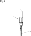
- the Figures 4 and 5 show the wiping plate 12 in side view.
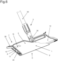
- Figure 6 shows a cleaning device 2 with a wiping plate 12 and wiping cover 1 attached thereto.
- the mop cover 1 is designed such that a layer 4 of the mop cover 1 only partially covers the base body 18 of the mop plate 12.
Landscapes
- Cleaning Implements For Floors, Carpets, Furniture, Walls, And The Like (AREA)
Description
- Die Erfindung betrifft einen Wischbezug für ein Reinigungsgerät, umfassend flächig ausgebildete Lagen, welche jeweils eine erste Hauptseite und eine zweite Hauptseite ausbilden, wobei die ersten Hauptseiten einander abgewandt und die zweiten Hauptseiten einander zugewandt sind, wobei zumindest eine erste Hauptseite eine Wischfläche ausbildet, wobei die Lagen entlang einer ersten Kante miteinander verbunden sind und wobei die Lagen eine zweite Kante aufweisen, welche der ersten Kante gegenüberliegt und wobei die Lagen entlang der zweiten Kante eine Einführöffnung zur Aufnahme einer Wischplatte ausbilden. Die Erfindung betrifft ferner eine Wischplatte für ein Reinigungsgerät, umfassend einen Grundkörper mit einer ersten Wischplattenkante und einer der ersten Wischplattenkante gegenüberliegenden zweiten Wischplattenkante sowie quer hierzu angeordneten dritten und vierten Wischplattenkanten.
- Aus der
EP 1 704 808 B1 ist ein Wischbezug bekannt, welcher zwei Lagen umfasst, die derart miteinander verbunden sind, dass der Wischbezug taschenförmig ausgebildet ist und eine Einführseite zur Aufnahme einer länglich ausgebildeten Wischplatte eines Reinigungsgerätes aufweist. Die Einführseite ist an einer Längsseite angeordnet, wobei die Einführseite abschnittsweise unlösbar verschlossen ist. - Bei dem vorbekannten Wischbezug ist ein Aufspannen der Wischplatte dadurch möglich, dass die Wischplatte im Bereich einer Schmalseite in Längsrichtung flexibel ausgestaltet ist, so dass die Wischplatte zum Aufspannen auf den Wischbezug in Längsrichtung zusammengeschoben werden kann.
- Aus der
US 2018/0344123 A1 ist ein Wischbezug für ein Reinigungsgerät bekannt, umfassend flächig ausgebildete Lagen, welche jeweils eine erste Hauptseite und eine zweite Hauptseite ausbilden, wobei die ersten Hauptseiten einander abgewandt und die zweiten Hauptseiten einander zugewandt sind, wobei zumindest eine erste Hauptseite eine Wischfläche ausbildet, wobei die Lagen entlang einer ersten Kante miteinander verbunden sind und wobei die Lagen eine zweite Kante aufweisen, welche der ersten Kante gegenüberliegt und wobei die Lagen entlang der zweiten Kante eine Einführöffnung zur Aufnahme einer Wischplatte ausbilden. - Die
WO 2009/038517 A1 zeigt einen flächig ausgebildeten Wischbezug für ein Reinigungsgerät, welcher über die Kante einer Wischplatte eines Reinigungsgerät umgeschlagen werden kann. - Der Erfindung liegt die Aufgabe zugrunde, einen Wischbezug bereit zu stellen, welcher eine besonders einfache und kostengünstige Ausgestaltung einer Wischplatte ermöglicht.
- Diese Aufgabe wird mit den Merkmalen für den Anspruch 1 gelöst. Auf vorteilhafte Ausgestaltungen nehmen die Unteransprüche Bezug.
- Zur Lösung der Aufgabe sind die Lagen derart ausgestaltet und/oder miteinander verbunden, dass sich zum Einführen einer Wischplatte die Längserstreckung der Einführöffnung vergrößert, um sich nach dem Einführen der Wischplatte wieder zu verkürzen. Dadurch ist es möglich, eine Wischplatte in den Wischbezug einzuführen, welche starr ausgebildet ist und weder klappbare noch verschiebbare Elemente aufweist. Eine derartige Wischplatte kann kostengünstig hergestellt werden. Die Einführöffnung vergrößert die Längserstreckung auch dann, wenn der Wischbezug von der Wischplatte entfernt werden soll.
- Die Längserstreckung der ersten Kante kann größer sein als die Längserstreckung der zweiten Kante. In diesem Zusammenhang ist es insbesondere vorteilhaft, wenn die Lagen trapezförmig ausgebildet sind. Bei dieser Ausgestaltung kann die Wischplatte besonders einfach in den Wischbezug eingeführt werden. Die beiden Lagen können deckungsgleich ausgebildet sein. Dazu können die beiden Lagen materialeinheitlich und einstückig ausgebildet und unter Bildung der ersten Kante zusammengeklappt sein.
- Die Lagen können entlang der quer zur ersten Kante und zweiten Kante laufenden dritten und vierten Kante zumindest abschnittsweise miteinander verbunden sein. Bei dieser Ausgestaltung ergibt sich ein Wischbezug, welcher eine Tasche ausbildet, die über die Einführöffnung zugänglich ist. Durch die trapezförmige Gestalt der Tasche ist die über die Einführöffnung in den Wischbezug eingeführte Wischplatte formschlüssig gesichert.
- In einer alternativen Ausgestaltung ist denkbar, dass die Lagen rechteckig ausgebildet sind, wobei die Lagen entlang der ersten Kante sowie entlang der dritten und vierten Kante miteinander verbunden sind. Die zweite Kante bildet die Einführöffnung aus. Im Bereich der dritten und vierten Kante sind die Lagen derart verbunden, beispielsweise miteinander vernäht, dass die Längserstreckung der Einführöffnung kleiner ist als die Längserstreckung der zweiten Kante. Die Verbindungslinie, beispielsweise die Naht, verläuft vorzugweise schiefwinklig von der die erste Kante und die dritte Kante sowie die vierte Kante begrenzenden Ecke zur zweiten Kante und ist dort von der die zweite Kante und die dritte Kante sowie die vierte Kante begrenzenden Ecke beabstandet. Auch bei dieser Ausgestaltung bildet sich im Inneren des Wischbezugs eine Tasche mit einer Hinterschneidung auf, in welcher eine Wischplatte formschlüssig gehalten ist.
- Neben dem Vorteil der formschlüssigen Verbindung weisen der trapezförmige Wischbezug, beziehungsweise die trapezförmig miteinander verbundenen Lagen, den Vorteil auf, dass sich in Kombination mit einer trapezförmigen Wischplatte eine spitzwinklige und biegesteife Ecke ergibt, welche während der Reinigungsarbeit ein leichteres Erreichen von Raumecken ermöglicht.
- Gemäß einer ersten Ausgestaltung können eine der beiden Lagen oder beide Lagen elastisch ausgebildet sein. Hierzu kann entweder das Material der Lagen insgesamt elastisch ausgebildet sein oder in die Lagen können flexible Elemente, beispielsweise elastische Streifen, eingearbeitet sein, so dass die Lagen zur Vergrößerung der Einführöffnung in Längsrichtung elastisch dehnbar sind.
- Erfindungsgemäß sind die Lagen entlang der quer zu der ersten und zweiten Kante verlaufenden dritten und vierten Kante mittels eines Fixierelementes zumindest abschnittsweise miteinander verbunden, wobei das Fixierelement verformbar ist, um zur Aufnahme der Wischplatte die Einführöffnung zu vergrößern. Bei dieser Ausgestaltung ergibt sich die Flexibilität der Einführöffnung durch die elastische Ausgestaltung der Fixierelemente im Bereich der dritten Kante und/oder der vierten Kante. Hierbei ist vorteilhaft, dass die Lagen aus einem formstabilen Material hergestellt werden können und dadurch über die gesamte Fläche eine hohe Wischleistung aufweisen. Die flexible Ausgestaltung der Einführöffnung ergibt sich durch das verformbare Fixierelement.
- Das Fixierelement ist vorzugsweise elastisch ausgebildet. Dadurch ergibt sich eine elastische Ausgestaltung der Lagen im Bereich der dritten Kante und/oder der vierten Kante. Dabei kann das Fixierelement in die Kanten eingearbeitet sein und beispielsweise aus einem elastischen Garn bestehen, mit welchem die Lagen im Bereich der dritten Kante und vierten Kante miteinander verbunden sind. Alternativ kann die elastische Ausgestaltung auch durch die Art der Verbindung der beiden Lagen im Bereich der dritten und/oder vierten Kante erfolgen, also beispielsweise durch eine elastische Nahtführung.
- Das Fixierelement kann als Band oder Schnur ausgebildet sein. Das Fixierelement ist dabei jeweils an den Lagen festgelegt und verbindet dadurch die beiden Lagen im Bereich der dritten Kante und der vierten Kante miteinander. Dabei ist das Fixierelement vorzugsweise elastisch ausgebildet und bildet dadurch die elastische Ausgestaltung der Kanten, durch die sich wiederum die vergrößerbare Einführöffnung ergibt. Die Dehnungsrichtung des Fixierelementes ist bei der oben beschriebenen Anordnung parallel zur zweiten Kante.
- Vorzugsweise erstreckt sich das Fixierelement nicht über die gesamte Länge der dritten Kante und/oder der vierten Kante, wobei das Fixierelement dem Bereich der zweiten Kante zugeordnet ist. Dadurch ergibt sich eine unmittelbare Zuordnung des Fixierelementes, insbesondere des elastisch ausgebildeten Bandes zu der Einführöffnung.
- An der dritten Kante und/oder an der vierten Kante kann sich in dem der ersten Kante zugeordneten Abschnitt jeweils eine Öffnung ergeben. Diese Ausgestaltung ermöglicht eine besonders gute Reinigung der durch die beiden Lagen gebildeten Tasche. Insbesondere kann die Entstehung von geschlossenen innenliegenden Eckbereichen vermieden werden, in denen sich Verschmutzungen ansammeln können.
- In einer alternativen Ausgestaltung des Wischbezuges kann vorgesehen sein, dass zumindest eine der Lagen so ausgebildet ist, dass diese die Wischplatte nur teilweise bedeckt. Dementsprechend ist beispielsweise eine Lage kleiner ausgebildet als die andere Lage und die Hauptseiten der kleineren Lage bedecken eine in dem Wischbezug aufgenommene Wischplatte nur teilweise. Hierbei ist insbesondere denkbar, dass die nur teilweise ausgebildete Lage die Wischplatte lediglich im Bereich der ersten Kante sowie der dritten und vierten Kante teilweise bedeckt.
- Die Wischplatte für ein Reinigungsgerät umfasst einen Grundkörper mit einer ersten Wischplattenkante und einer der ersten Wischplattenkante gegenüberliegenden zweiten Wischplattenkante sowie quer hierzu angeordneten dritten und vierten Wischplattenkanten, wobei der Grundkörper im Wesentlichen starr ausgebildet ist, wobei der dritten Wischplattenkante und/oder der vierten Wischplattenkante eine Abwurfeinrichtung zugeordnet ist, welche ausgebildet ist, einen auf dem Grundkörper befestigten Wischbezug abzuwerfen. Die Wischplatte weist dabei keinerlei verschiebbare oder verkürzbare Flügel, beispielsweise Schiebeflügel oder Schwenkflügel, auf. Dadurch kann die Wischplatte kostengünstig hergestellt werden. Des Weiteren können verdeckte Bereiche minimiert und weitestgehend vermieden werden, so dass die Wischplatte bei Bedarf einfach und hygienisch gereinigt werden kann. Dadurch eignet sich die Wischplatte mit dem Wischbezug insbesondere für den Einsatz in hygienesensitiven Bereichen, beispielsweise zur Reinigung von Krankenhäusern oder Reinräumen. Die Abwurfeinrichtung ermöglicht es, einen Wischbezug von der Wischplatte zu entfernen, ohne dass der Wischbezug berührt werden muss.
- Die Abwurfeinrichtung kann als Hebel ausgebildet sein. Dabei ist der Hebel vorzugsweise im Bereich der ersten Wischplattenkante an den Grundkörper angebunden. Des Weiteren ist es vorteilhaft, wenn sich der Hebel zumindest abschnittsweise über die zweite Wischplattenkante erstreckt. Dadurch kann die Abwurfeinrichtung besonders gut gegriffen werden und der Wischbezug kann einfach und ergonomisch von der Wischplatte entfernt werden.
- Die dritte Wischplattenkante und die vierte Wischplattenkante können in dem der zweiten Wischplattenkante zugeordneten Bereich senkrecht zur zweiten Wischplattenkante verlaufen und die dritte Wischplattenkante und die vierte Wischplattenkante können in dem der ersten Wischplattenkante zugeordneten Bereich schräg zur ersten Wischplattenkante verlaufen. Diese Ausgestaltung ist insbesondere im Zusammenhang mit einem Wischbezug vorteilhaft, welcher im Bereich der dritten Kante und der vierten Kante mit einem elastisch ausgebildeten, insbesondere bandförmigen Fixierelement ausgerüstet ist. Dabei ist der dem Fixierelement zugeordnete Abschnitt der Wischplatte so ausgebildet, dass sich eine gerade Führung des Fixierelementes ergibt. Dadurch ist ein sicherer Halt des Wischbezuges auf der Wischplatte gewährleistet. Zur Verbesserung der Fixierung kann an dem der zweiten Wischplattenkante zugeordneten Abschnitt von dritter Wischplattenkante und vierter Wischplattenkante ein Vorsprung vorgesehen sein. Durch diesen ist das Fixierelement jeweils zusätzlich quer zur zweiten Kante formschlüssig fixiert. Der Vorsprung kann dabei aus der Abwurfeinrichtung ausgebildet sein, so dass gleichzeitig ein einfaches Entfernen des Wischbezuges möglich ist.
- Durch den zweiten schräg verlaufenden Abschnitt ergibt sich wiederum die trapezoide Gestalt der Wischplatte und eine große Wischfläche, was mit einer hohen Flächenleistung einhergeht.
- Die Wischplatte ist vorzugsweise über ein kardanisches Gelenk mit einem Stiel verbunden. Die Anlenkung des Gelenks erfolgt dabei auf einer Hauptseite der Wischplatte, bevorzugt in etwa mittig. Dadurch kann der Druck, den ein Benutzer über den Stiel auf die Wischplatte aufbringt, gleichmäßig auf die Wischfläche verteilt werden. Bei einem Wischbezug, der die Wischplatte beidseitig umgibt und zwei Wischflächen ausbildet, kann der Benutzer während des Reinigungsvorgangs durch Schwenken der Wischplatte von der einen Wischfläche auf die andere Wischfläche wechseln und so wechselseitig erst die eine Lage und dann die andere Lage in Eingriff mit dem zu reinigenden Boden bringen. Dabei ist es nicht erforderlich, den Wischbezug von der Wischplatte zu entfernen.
- Beim Wischen liegt die dem Boden zugewandte Lage immer flach an der Wischplatte an, während das mittig von der Wischplatte abragende Gelenk die andere Lage von der Wischplatte abheben kann.
- Dies kann in einer ersten alternativen Ausgestaltung vermieden werden, indem die beiden Lagen des Wischbezuges in der zweiten Kante in dem dem Gelenk zugordneten Abschnitt einen Ausschnitt, beispielsweise in Form eines Schlitzes, aufweisen. Durch den Schlitz können das Gelenk und der Stiel hindurchragen, insbesondere wenn der Stiel weitgehend senkrecht zur Wischplatte ausgerichtet ist.
- In einer zweiten alternativen Ausgestaltung kann die zweite Kante der beiden Lagen weitgehend ununterbrochen sein. Es wird also vermieden, in die zweite Kante einen Schlitz einzubringen. Bei dieser Ausgestaltung kann die obere Lage durch die elastischen Fixierelemente, welche die beiden Lagen verbinden, elastisch von der Wischplatte abgehoben werden und dadurch dem Gelenk und dem Stiel ausweichen.
- Ein Reinigungsgerät umfasst einen erfindungsgemäßen Wischbezug und eine Wischplatte.
- Der Wischbezug kann dabei so ausgebildet sein, dass eine Lage des Wischbezugs den Grundkörper der Wischplatte nur teilweise bedeckt. Dadurch ergibt sich ein besonders kostengünstig herstellbarer Wischbezug.
- In einer alternativen Ausgestaltung kann die Wischplatte auch rechteckig ausgebildet sein. Bei dieser Ausgestaltung ist die Tasche des Wischbezuges ebenfalls rechteckig ausgebildet. Damit der Wischbezug sicher an der Wischplatte fixiert ist, können an der Wischplatte reibungserhöhende Elemente vorgesehen sein, welche die Reibung zwischen dem elastischen Band des Wischbezuges und der Wischplattenkante erhöhen. Denkbar sind in diesem Zusammenhang insbesondere elastisch ausgebildete Abschnitte der Wischplattenkante, beispielsweise ausgebildet aus einem spritzgießfähigen elastischen Werkstoff. Denkbar sind ferner reibungserhöhende Strukturen an der Wischplattenkante, beispielsweise durch abschnittsweises Aufrauen oder durch eine Riffelung oder Zahnstruktur. Durch die reibungserhöhende Struktur ist der Wischbezug sicher an der Wischplatte fixiert.
- Einige Ausgestaltungen des erfindungsgemäßen Wischbezuges werden nachfolgend anhand der Figuren näher erläutert. Diese zeigen, jeweils schematisch:
- Fig. 1
- einen Wischbezug;
- Fig. 2
- einen Wischbezug vor der Montage;
- Fig. 3
- ein Reinigungsgerät mit Wischplatte in der Vorderansicht;
- Fig. 4
- ein Reinigungsgerät mit Wischplatte in der Seitenansicht;
- Fig. 5
- ein Reinigungsgerät mit Wischplatte in der Wischposition;
- Fig. 6
- ein Reinigungsgerät in dreidimensionaler Darstellung.
- Die Figuren zeigen einen Wischbezug 1 für ein Reinigungsgerät 2, wobei das Reinigungsgerät 2 als Flachwischer ausgebildet ist und eine Wischplatte 12 aufweist, an der über ein Gelenk 24 ein Stiel 25 angebunden ist.
-
Figur 1 zeigt den Wischbezug 1. Der Wischbezug 1 umfasst flächig ausgebildete Lagen 3, 4, welche auf der ersten Hauptseite 5, 6 eine Wischfläche ausbilden. Die Lagen 3, 4 sind so zueinander angeordnet, dass die zweiten Hauptseiten 7, 8 einander zugewandt sind. Die Lagen 3, 4 sind entlang einer ersten Kante 9 miteinander verbunden und weisen eine zweite Kante 10 auf, welche der ersten Kante 9 gegenüberliegt. In der zweiten Kante 10 ist eine Einführöffnung 11 für eine Wischplatte 12 ausgebildet. - Die Lagen 3, 4 sind derart ausgestaltet und/oder miteinander verbunden, dass sich zum Einführen einer Wischplatte 12 die Längserstreckung der Einführöffnung 11 vergrößert, um sich nach dem Einführen der Wischplatte 12 wieder zu verkürzen.
- Die Lagen 3, 4 des Wischbezugs 1 sind so ausgebildet, dass im unbelasteten Zustand die Längserstreckung der ersten Kante 9 größer ist als die Längserstreckung der zweiten Kante 10. Bei dieser Ausgestaltung sind die Lagen 3, 4 trapezförmig ausgebildet und ermöglichen eine formschlüssige Aufnahme einer Wischplatte 12.
- Die Lagen 3, 4 sind entlang der quer zur ersten und zweiten Kante 9, 10 verlaufenden dritten und vierten Kante 13, 14 abschnittsweise miteinander verbunden. Dies erfolgt durch ein an den Lagen 3, 4 festgelegtes Fixierelement 15, durch welches die Lagen 3, 4 im Bereich der dritten und vierten Kante 13, 14 abschnittsweise miteinander verbunden sind. Das Fixierelement 15 ist in Form eines elastischen Bandes ausgebildet. Dadurch sind die Lagen 3, 4 im Bereich der dritten und vierten Kante 13, 14 elastisch ausgebildet und die zweite Kante 10 kann zur Vergrößerung der Einführöffnung 11 elastisch gedehnt werden.
- Das Fixierelement (15) erstreckt sich dabei nicht über die gesamte Erstreckung der dritten und vierten Kante 13, 14, sondern ist dem Bereich der zweiten Kante 10 zugeordnet. In dem der ersten Kante 9 zugeordneten Abschnitt von dritter und vierter Kante 13, 14 ergibt sich jeweils eine Öffnung 16, 17.
-
Figur 2 zeigt den Wischbezug 1 vor Abschluss der Montage. In diesem Zustand sind die Lagen 3, 4 noch nicht im Bereich der dritten und vierten Kante 13, 14 miteinander verbunden. Es ist zu erkennen, dass die Lagen 3, 4 materialeinheitlich und einstückig ausgebildet sind. -
Figur 3 zeigt eine Reinigungsgerät 2 mit einer Wischplatte 12. Die Wischplatte 12 umfasst einen Grundkörper 18 mit einer ersten Wischplattenkante 19 und einer der ersten Wischplattenkante 19 gegenüberliegenden zweiten Wischplattenkante 20. Quer zur ersten Wischplattenkante 19 und zweiten Wischplattenkante 20 sind dritte und vierte Wischplattenkanten 21, 22 ausgebildet. Der Grundkörper 18 ist starr ausgebildet. - Der dritten Wischplattenkante 21 und der vierten Wischplattenkante 22 ist jeweils eine Abwurfeinrichtung 23 zugeordnet, welche ausgebildet ist, einen auf dem Grundkörper 18 befestigten Wischbezug 1 abzuwerfen. Die Abwurfeinrichtung 23 ist als Hebel ausgebildet, wobei der Hebel im Bereich der ersten Wischplattenkante 19 gelenkig an den Grundkörper 18 angebunden ist.
- Die dritte Wischplattenkante 21 und die vierte Wischplattenkante 22 verlaufen in dem der zweiten Wischplattenkante 20 zugeordneten Bereich senkrecht zur zweiten Wischplattenkante 20. Des Weiteren verlaufen die dritte Wischplattenkante 21 und die vierte Wischplattenkante 22 in dem der ersten Wischplattenkante 19 zugeordneten Bereich schräg zur ersten Wischplattenkante 19.
- In den Eckbereichen zwischen zweiter Wischplattenkante 20 und dritter Wischplattenkante 21 sowie zwischen zweiter Wischplattenkante 20 und vierter Wischplattenkante 22 sind Vorsprünge 26 angeordnet, welche in einen Handgriff münden. Durch die Vorsprünge 26 ist der auf die Wischplatte 12 aufgezogene Wischbezug 1 zusätzlich formschlüssig auf der Wischplatte 12 gehalten. Die Vorsprünge 26 verhindern zusätzlich ein unabsichtliches Heruntergleiten der Fixierelemente 15.
- Die
Figuren 4 und5 zeigen die Wischplatte 12 in der Seitenansicht. -
Figur 6 zeigt ein Reinigungsgerät 2 mit einer Wischplatte 12 und daran befestigtem Wischbezug 1. - In einer vorteilhaften Ausgestaltung ist der Wischbezug 1 so ausgebildet, dass eine Lage 4 des Wischbezuges 1 den Grundkörper 18 der Wischplatte 12 nur teilweise bedeckt.
Claims (7)
- Wischbezug (1) für ein Reinigungsgerät (2), umfassend flächig ausgebildete Lagen (3, 4), welche jeweils eine erste Hauptseite (5, 6) und eine zweite Hauptseite (7, 8) ausbilden, wobei die ersten Hauptseiten (5, 6) einander abgewandt und die zweiten Hauptseiten (7, 8) einander zugewandt sind, wobei zumindest eine erste Hauptseite (5, 6) eine Wischfläche ausbildet, wobei die Lagen (3, 4) entlang einer ersten Kante (9) miteinander verbunden sind und wobei die Lagen (3, 4) eine zweite Kante (10) aufweisen, welche der ersten Kante (9) gegenüberliegt und wobei die Lagen (3, 4) entlang der zweiten Kante (10) eine Einführöffnung (11) zur Aufnahme einer Wischplatte (12) ausbilden, wobei die Lagen (3, 4) derart ausgestaltet und/oder miteinander verbunden sind, dass sich zum Einführen einer Wischplatte (12) die Längserstreckung der Einführöffnung (11) vergrößert, um sich nach dem Einführen der Wischplatte (12) wieder zu verkürzen, dadurch gekennzeichnet, dass die Lagen (3, 4) entlang der quer zu der ersten und zweiten Kante (9, 10) verlaufenden dritten und vierten Kante (13, 14) mittels eines Fixierelementes (15) zumindest abschnittsweise miteinander verbunden sind, wobei das Fixierelement (15) verformbar ist, um zur Aufnahme der Wischplatte (12) die Einführöffnung (11) zu vergrößern.
- Wischbezug nach Anspruch 1, dadurch gekennzeichnet, dass die Längserstreckung der ersten Kante (9) größer ist als die Längserstreckung der zweiten Kante (10).
- Wischbezug nach Anspruch 1 oder 2, dadurch gekennzeichnet, dass die Lagen (3, 4) trapezförmig ausgebildet sind.
- Wischbezug nach Anspruch 1, dadurch gekennzeichnet, dass das Fixierelement (15) elastisch ausgebildet ist.
- Wischbezug nach Anspruch 1 oder 4, dadurch gekennzeichnet, dass das Fixierelement (15) an den Lagen (3, 4) festgelegt ist und die Lagen (3, 4) im Bereich der dritten Kante (13) und der vierten Kante (14) zumindest abschnittsweise miteinander verbindet.
- Wischbezug nach Anspruch 1, 4 oder 5, dadurch gekennzeichnet, dass das Fixierelement (15) als Band oder als Schnur ausgebildet ist.
- Wischbezug nach einem der Ansprüche 1, 4 bis 6, dadurch gekennzeichnet, dass sich an der dritten Kante (13) und der vierten Kante (14) in dem der ersten Kante (9) zugeordneten Abschnitt jeweils eine Öffnung (16, 17) ergibt.
Applications Claiming Priority (1)
| Application Number | Priority Date | Filing Date | Title |
|---|---|---|---|
| DE102020104787.8A DE102020104787A1 (de) | 2020-02-24 | 2020-02-24 | Wischbezug für ein Reinigungsgerät, Wischplatte für ein Reinigungsgerät und Reinigungsgerät |
Publications (3)
| Publication Number | Publication Date |
|---|---|
| EP3871582A2 EP3871582A2 (de) | 2021-09-01 |
| EP3871582A3 EP3871582A3 (de) | 2021-11-24 |
| EP3871582B1 true EP3871582B1 (de) | 2024-05-08 |
Family
ID=74550549
Family Applications (1)
| Application Number | Title | Priority Date | Filing Date |
|---|---|---|---|
| EP21155023.1A Active EP3871582B1 (de) | 2020-02-24 | 2021-02-03 | Wischbezug für ein reinigungsgerät |
Country Status (2)
| Country | Link |
|---|---|
| EP (1) | EP3871582B1 (de) |
| DE (1) | DE102020104787A1 (de) |
Family Cites Families (8)
| Publication number | Priority date | Publication date | Assignee | Title |
|---|---|---|---|---|
| FI68514C (fi) * | 1983-05-17 | 1985-10-10 | Ahti Heinonen | Anordning foer staedning av golvet |
| EP1704808B1 (de) | 2005-03-16 | 2007-12-19 | Carl Freudenberg KG | Wischbezug |
| SE533617C2 (sv) * | 2007-09-17 | 2010-11-09 | Vikan Ab | Putsmopp och förfarande för att ta bort fläckar från glasytor |
| DE102009060007A1 (de) * | 2009-12-21 | 2011-06-22 | Carl Freudenberg KG, 69469 | Wischplatte für ein Reinigungsgerät |
| DE102011107319B4 (de) * | 2011-07-06 | 2014-05-15 | Carl Freudenberg Kg | Flachwischer und Trägerplatte dafür |
| GB2559190A (en) * | 2017-01-31 | 2018-08-01 | Ronald Alexander Scot Young | Mop, mop head and method of fitting |
| US20180344123A1 (en) * | 2017-06-05 | 2018-12-06 | Josephine Santina Amatucci | Grandma's Rag Mop |
| DE202018102701U1 (de) * | 2018-05-15 | 2018-10-15 | Arnold Fischer | Moppbezug für die Verwendung auf einem Mopphalter |
-
2020
- 2020-02-24 DE DE102020104787.8A patent/DE102020104787A1/de not_active Ceased
-
2021
- 2021-02-03 EP EP21155023.1A patent/EP3871582B1/de active Active
Also Published As
| Publication number | Publication date |
|---|---|
| DE102020104787A1 (de) | 2021-08-26 |
| EP3871582A2 (de) | 2021-09-01 |
| EP3871582A3 (de) | 2021-11-24 |
Similar Documents
| Publication | Publication Date | Title |
|---|---|---|
| DE59603271C5 (de) | Mophalter sowie Mopbezug hierfür | |
| DE69613667T2 (de) | Wischgerät | |
| DE60031415T2 (de) | Reinigungsgerät mit vorrichtungen zum befestigen eines tuches | |
| WO2006097154A1 (de) | Wischbezug | |
| DE20023550U1 (de) | Halter zur Befestigung eines Wischmops am Ende eines Stiels | |
| DE102008030309B4 (de) | Reinigungsgerät | |
| WO2012031691A1 (de) | Befestigungseinrichtung | |
| EP3871582A2 (de) | Wischbezug für ein reinigungsgerät, wischplatte für ein reinigungsgerät und reinigungsgerät | |
| EP1753336B1 (de) | Wischplatte mit wischbezug | |
| EP1342445B1 (de) | Wischgerät | |
| EP2949253B1 (de) | SAUGFUß FÜR EINE BODENREINIGUNGSMASCHINE | |
| WO2007042128A1 (de) | Reinigungsgerät mit einem reinigungsschwamm für boden-, wand- und/oder fensterreinigung | |
| DE102004026837B4 (de) | Wischsystem, Auswringvorrichtung und Wischgerät | |
| EP2116166A1 (de) | Reinigungsvorrichtung mit Mehrfachnutzungsmöglichkeit | |
| EP3662806B1 (de) | Bodenreinigungsgerät und bodenreinigungssystem | |
| DE102005009632A1 (de) | Reinigungskörper sowie Flügelmopp mit diesem Reinigungskörper | |
| EP3801170B1 (de) | Wischplatte | |
| EP1853151B1 (de) | Flächenreinigungsgerät | |
| EP4475733A1 (de) | Rahmensystem und reinigungsgeräte-rahmen | |
| DE102006027284B4 (de) | Vorrichtung und Verfahren zum Reinigen von Böden | |
| DE102006019903B3 (de) | Reinigungsgerät und Reinigungssystem | |
| EP2481334A1 (de) | Wischerplatte mit Wischbezugklemme | |
| EP2323530B1 (de) | Reinigungsgerät | |
| WO2007042285A2 (de) | Reinigungsgerät mit tragkörper und reinigungskörper spezieller geometrie | |
| DE202007010604U1 (de) | Reinigungsgerät mit einem plattenartigen Trägerteil |
Legal Events
| Date | Code | Title | Description |
|---|---|---|---|
| PUAI | Public reference made under article 153(3) epc to a published international application that has entered the european phase |
Free format text: ORIGINAL CODE: 0009012 |
|
| STAA | Information on the status of an ep patent application or granted ep patent |
Free format text: STATUS: THE APPLICATION HAS BEEN PUBLISHED |
|
| AK | Designated contracting states |
Kind code of ref document: A2 Designated state(s): AL AT BE BG CH CY CZ DE DK EE ES FI FR GB GR HR HU IE IS IT LI LT LU LV MC MK MT NL NO PL PT RO RS SE SI SK SM TR |
|
| PUAL | Search report despatched |
Free format text: ORIGINAL CODE: 0009013 |
|
| AK | Designated contracting states |
Kind code of ref document: A3 Designated state(s): AL AT BE BG CH CY CZ DE DK EE ES FI FR GB GR HR HU IE IS IT LI LT LU LV MC MK MT NL NO PL PT RO RS SE SI SK SM TR |
|
| RIC1 | Information provided on ipc code assigned before grant |
Ipc: A47L 13/256 20060101AFI20211021BHEP |
|
| STAA | Information on the status of an ep patent application or granted ep patent |
Free format text: STATUS: REQUEST FOR EXAMINATION WAS MADE |
|
| 17P | Request for examination filed |
Effective date: 20220511 |
|
| RBV | Designated contracting states (corrected) |
Designated state(s): AL AT BE BG CH CY CZ DE DK EE ES FI FR GB GR HR HU IE IS IT LI LT LU LV MC MK MT NL NO PL PT RO RS SE SI SK SM TR |
|
| GRAP | Despatch of communication of intention to grant a patent |
Free format text: ORIGINAL CODE: EPIDOSNIGR1 |
|
| STAA | Information on the status of an ep patent application or granted ep patent |
Free format text: STATUS: GRANT OF PATENT IS INTENDED |
|
| GRAJ | Information related to disapproval of communication of intention to grant by the applicant or resumption of examination proceedings by the epo deleted |
Free format text: ORIGINAL CODE: EPIDOSDIGR1 |
|
| GRAP | Despatch of communication of intention to grant a patent |
Free format text: ORIGINAL CODE: EPIDOSNIGR1 |
|
| INTG | Intention to grant announced |
Effective date: 20231128 |
|
| RIN1 | Information on inventor provided before grant (corrected) |
Inventor name: MESSINEO, CARLO Inventor name: EISENHUT, ANDREAS Inventor name: SAND, NIKOLAI Inventor name: DUNKEL, JOERG Inventor name: REIMAN, ULLA Inventor name: JUERGENS, MARTINA Inventor name: FALLENSTEIN, FELIX Inventor name: PLATE, TORSTEN Inventor name: HECKER, MATTHIAS |
|
| INTG | Intention to grant announced |
Effective date: 20231128 |
|
| RIN1 | Information on inventor provided before grant (corrected) |
Inventor name: MESSINEO, CARLO Inventor name: EISENHUT, ANDREAS Inventor name: SAND, NIKOLAI Inventor name: DUNKEL, JOERG Inventor name: REIMAN, ULLA Inventor name: JUERGENS, MARTINA Inventor name: FALLENSTEIN, FELIX Inventor name: PLATE, TORSTEN Inventor name: HECKER, MATTHIAS |
|
| GRAS | Grant fee paid |
Free format text: ORIGINAL CODE: EPIDOSNIGR3 |
|
| GRAA | (expected) grant |
Free format text: ORIGINAL CODE: 0009210 |
|
| STAA | Information on the status of an ep patent application or granted ep patent |
Free format text: STATUS: THE PATENT HAS BEEN GRANTED |
|
| AK | Designated contracting states |
Kind code of ref document: B1 Designated state(s): AL AT BE BG CH CY CZ DE DK EE ES FI FR GB GR HR HU IE IS IT LI LT LU LV MC MK MT NL NO PL PT RO RS SE SI SK SM TR |
|
| REG | Reference to a national code |
Ref country code: GB Ref legal event code: FG4D Free format text: NOT ENGLISH |
|
| REG | Reference to a national code |
Ref country code: CH Ref legal event code: EP |
|
| REG | Reference to a national code |
Ref country code: DE Ref legal event code: R096 Ref document number: 502021003628 Country of ref document: DE |
|
| REG | Reference to a national code |
Ref country code: IE Ref legal event code: FG4D Free format text: LANGUAGE OF EP DOCUMENT: GERMAN |
|
| REG | Reference to a national code |
Ref country code: LT Ref legal event code: MG9D |
|
| REG | Reference to a national code |
Ref country code: NL Ref legal event code: MP Effective date: 20240508 |
|
| PG25 | Lapsed in a contracting state [announced via postgrant information from national office to epo] |
Ref country code: IS Free format text: LAPSE BECAUSE OF FAILURE TO SUBMIT A TRANSLATION OF THE DESCRIPTION OR TO PAY THE FEE WITHIN THE PRESCRIBED TIME-LIMIT Effective date: 20240908 |
|
| PG25 | Lapsed in a contracting state [announced via postgrant information from national office to epo] |
Ref country code: BG Free format text: LAPSE BECAUSE OF FAILURE TO SUBMIT A TRANSLATION OF THE DESCRIPTION OR TO PAY THE FEE WITHIN THE PRESCRIBED TIME-LIMIT Effective date: 20240508 |
|
| PG25 | Lapsed in a contracting state [announced via postgrant information from national office to epo] |
Ref country code: FI Free format text: LAPSE BECAUSE OF FAILURE TO SUBMIT A TRANSLATION OF THE DESCRIPTION OR TO PAY THE FEE WITHIN THE PRESCRIBED TIME-LIMIT Effective date: 20240508 Ref country code: HR Free format text: LAPSE BECAUSE OF FAILURE TO SUBMIT A TRANSLATION OF THE DESCRIPTION OR TO PAY THE FEE WITHIN THE PRESCRIBED TIME-LIMIT Effective date: 20240508 |
|
| PG25 | Lapsed in a contracting state [announced via postgrant information from national office to epo] |
Ref country code: GR Free format text: LAPSE BECAUSE OF FAILURE TO SUBMIT A TRANSLATION OF THE DESCRIPTION OR TO PAY THE FEE WITHIN THE PRESCRIBED TIME-LIMIT Effective date: 20240809 |
|
| PG25 | Lapsed in a contracting state [announced via postgrant information from national office to epo] |
Ref country code: PT Free format text: LAPSE BECAUSE OF FAILURE TO SUBMIT A TRANSLATION OF THE DESCRIPTION OR TO PAY THE FEE WITHIN THE PRESCRIBED TIME-LIMIT Effective date: 20240909 |
|
| PG25 | Lapsed in a contracting state [announced via postgrant information from national office to epo] |
Ref country code: NL Free format text: LAPSE BECAUSE OF FAILURE TO SUBMIT A TRANSLATION OF THE DESCRIPTION OR TO PAY THE FEE WITHIN THE PRESCRIBED TIME-LIMIT Effective date: 20240508 |
|
| PG25 | Lapsed in a contracting state [announced via postgrant information from national office to epo] |
Ref country code: ES Free format text: LAPSE BECAUSE OF FAILURE TO SUBMIT A TRANSLATION OF THE DESCRIPTION OR TO PAY THE FEE WITHIN THE PRESCRIBED TIME-LIMIT Effective date: 20240508 |
|
| PG25 | Lapsed in a contracting state [announced via postgrant information from national office to epo] |
Ref country code: PL Free format text: LAPSE BECAUSE OF FAILURE TO SUBMIT A TRANSLATION OF THE DESCRIPTION OR TO PAY THE FEE WITHIN THE PRESCRIBED TIME-LIMIT Effective date: 20240508 |
|
| PG25 | Lapsed in a contracting state [announced via postgrant information from national office to epo] |
Ref country code: LV Free format text: LAPSE BECAUSE OF FAILURE TO SUBMIT A TRANSLATION OF THE DESCRIPTION OR TO PAY THE FEE WITHIN THE PRESCRIBED TIME-LIMIT Effective date: 20240508 |
|
| PG25 | Lapsed in a contracting state [announced via postgrant information from national office to epo] |
Ref country code: PT Free format text: LAPSE BECAUSE OF FAILURE TO SUBMIT A TRANSLATION OF THE DESCRIPTION OR TO PAY THE FEE WITHIN THE PRESCRIBED TIME-LIMIT Effective date: 20240909 Ref country code: PL Free format text: LAPSE BECAUSE OF FAILURE TO SUBMIT A TRANSLATION OF THE DESCRIPTION OR TO PAY THE FEE WITHIN THE PRESCRIBED TIME-LIMIT Effective date: 20240508 Ref country code: NO Free format text: LAPSE BECAUSE OF FAILURE TO SUBMIT A TRANSLATION OF THE DESCRIPTION OR TO PAY THE FEE WITHIN THE PRESCRIBED TIME-LIMIT Effective date: 20240808 Ref country code: NL Free format text: LAPSE BECAUSE OF FAILURE TO SUBMIT A TRANSLATION OF THE DESCRIPTION OR TO PAY THE FEE WITHIN THE PRESCRIBED TIME-LIMIT Effective date: 20240508 Ref country code: LV Free format text: LAPSE BECAUSE OF FAILURE TO SUBMIT A TRANSLATION OF THE DESCRIPTION OR TO PAY THE FEE WITHIN THE PRESCRIBED TIME-LIMIT Effective date: 20240508 Ref country code: IS Free format text: LAPSE BECAUSE OF FAILURE TO SUBMIT A TRANSLATION OF THE DESCRIPTION OR TO PAY THE FEE WITHIN THE PRESCRIBED TIME-LIMIT Effective date: 20240908 Ref country code: HR Free format text: LAPSE BECAUSE OF FAILURE TO SUBMIT A TRANSLATION OF THE DESCRIPTION OR TO PAY THE FEE WITHIN THE PRESCRIBED TIME-LIMIT Effective date: 20240508 Ref country code: GR Free format text: LAPSE BECAUSE OF FAILURE TO SUBMIT A TRANSLATION OF THE DESCRIPTION OR TO PAY THE FEE WITHIN THE PRESCRIBED TIME-LIMIT Effective date: 20240809 Ref country code: FI Free format text: LAPSE BECAUSE OF FAILURE TO SUBMIT A TRANSLATION OF THE DESCRIPTION OR TO PAY THE FEE WITHIN THE PRESCRIBED TIME-LIMIT Effective date: 20240508 Ref country code: ES Free format text: LAPSE BECAUSE OF FAILURE TO SUBMIT A TRANSLATION OF THE DESCRIPTION OR TO PAY THE FEE WITHIN THE PRESCRIBED TIME-LIMIT Effective date: 20240508 Ref country code: BG Free format text: LAPSE BECAUSE OF FAILURE TO SUBMIT A TRANSLATION OF THE DESCRIPTION OR TO PAY THE FEE WITHIN THE PRESCRIBED TIME-LIMIT Effective date: 20240508 Ref country code: RS Free format text: LAPSE BECAUSE OF FAILURE TO SUBMIT A TRANSLATION OF THE DESCRIPTION OR TO PAY THE FEE WITHIN THE PRESCRIBED TIME-LIMIT Effective date: 20240808 |
|
| PG25 | Lapsed in a contracting state [announced via postgrant information from national office to epo] |
Ref country code: DK Free format text: LAPSE BECAUSE OF FAILURE TO SUBMIT A TRANSLATION OF THE DESCRIPTION OR TO PAY THE FEE WITHIN THE PRESCRIBED TIME-LIMIT Effective date: 20240508 |
|
| PG25 | Lapsed in a contracting state [announced via postgrant information from national office to epo] |
Ref country code: EE Free format text: LAPSE BECAUSE OF FAILURE TO SUBMIT A TRANSLATION OF THE DESCRIPTION OR TO PAY THE FEE WITHIN THE PRESCRIBED TIME-LIMIT Effective date: 20240508 |
|
| PG25 | Lapsed in a contracting state [announced via postgrant information from national office to epo] |
Ref country code: CZ Free format text: LAPSE BECAUSE OF FAILURE TO SUBMIT A TRANSLATION OF THE DESCRIPTION OR TO PAY THE FEE WITHIN THE PRESCRIBED TIME-LIMIT Effective date: 20240508 |
|
| PG25 | Lapsed in a contracting state [announced via postgrant information from national office to epo] |
Ref country code: SK Free format text: LAPSE BECAUSE OF FAILURE TO SUBMIT A TRANSLATION OF THE DESCRIPTION OR TO PAY THE FEE WITHIN THE PRESCRIBED TIME-LIMIT Effective date: 20240508 Ref country code: RO Free format text: LAPSE BECAUSE OF FAILURE TO SUBMIT A TRANSLATION OF THE DESCRIPTION OR TO PAY THE FEE WITHIN THE PRESCRIBED TIME-LIMIT Effective date: 20240508 |
|
| PG25 | Lapsed in a contracting state [announced via postgrant information from national office to epo] |
Ref country code: SM Free format text: LAPSE BECAUSE OF FAILURE TO SUBMIT A TRANSLATION OF THE DESCRIPTION OR TO PAY THE FEE WITHIN THE PRESCRIBED TIME-LIMIT Effective date: 20240508 |
|
| PG25 | Lapsed in a contracting state [announced via postgrant information from national office to epo] |
Ref country code: SM Free format text: LAPSE BECAUSE OF FAILURE TO SUBMIT A TRANSLATION OF THE DESCRIPTION OR TO PAY THE FEE WITHIN THE PRESCRIBED TIME-LIMIT Effective date: 20240508 Ref country code: SK Free format text: LAPSE BECAUSE OF FAILURE TO SUBMIT A TRANSLATION OF THE DESCRIPTION OR TO PAY THE FEE WITHIN THE PRESCRIBED TIME-LIMIT Effective date: 20240508 Ref country code: RO Free format text: LAPSE BECAUSE OF FAILURE TO SUBMIT A TRANSLATION OF THE DESCRIPTION OR TO PAY THE FEE WITHIN THE PRESCRIBED TIME-LIMIT Effective date: 20240508 Ref country code: EE Free format text: LAPSE BECAUSE OF FAILURE TO SUBMIT A TRANSLATION OF THE DESCRIPTION OR TO PAY THE FEE WITHIN THE PRESCRIBED TIME-LIMIT Effective date: 20240508 Ref country code: DK Free format text: LAPSE BECAUSE OF FAILURE TO SUBMIT A TRANSLATION OF THE DESCRIPTION OR TO PAY THE FEE WITHIN THE PRESCRIBED TIME-LIMIT Effective date: 20240508 Ref country code: CZ Free format text: LAPSE BECAUSE OF FAILURE TO SUBMIT A TRANSLATION OF THE DESCRIPTION OR TO PAY THE FEE WITHIN THE PRESCRIBED TIME-LIMIT Effective date: 20240508 |
|
| PG25 | Lapsed in a contracting state [announced via postgrant information from national office to epo] |
Ref country code: IT Free format text: LAPSE BECAUSE OF FAILURE TO SUBMIT A TRANSLATION OF THE DESCRIPTION OR TO PAY THE FEE WITHIN THE PRESCRIBED TIME-LIMIT Effective date: 20240508 |
|
| REG | Reference to a national code |
Ref country code: DE Ref legal event code: R097 Ref document number: 502021003628 Country of ref document: DE |
|
| PLBE | No opposition filed within time limit |
Free format text: ORIGINAL CODE: 0009261 |
|
| STAA | Information on the status of an ep patent application or granted ep patent |
Free format text: STATUS: NO OPPOSITION FILED WITHIN TIME LIMIT |
|
| 26N | No opposition filed |
Effective date: 20250211 |
|
| PG25 | Lapsed in a contracting state [announced via postgrant information from national office to epo] |
Ref country code: SI Free format text: LAPSE BECAUSE OF FAILURE TO SUBMIT A TRANSLATION OF THE DESCRIPTION OR TO PAY THE FEE WITHIN THE PRESCRIBED TIME-LIMIT Effective date: 20240508 |
|
| PGFP | Annual fee paid to national office [announced via postgrant information from national office to epo] |
Ref country code: AT Payment date: 20250417 Year of fee payment: 5 |
|
| PG25 | Lapsed in a contracting state [announced via postgrant information from national office to epo] |
Ref country code: SE Free format text: LAPSE BECAUSE OF FAILURE TO SUBMIT A TRANSLATION OF THE DESCRIPTION OR TO PAY THE FEE WITHIN THE PRESCRIBED TIME-LIMIT Effective date: 20240508 |
|
| PG25 | Lapsed in a contracting state [announced via postgrant information from national office to epo] |
Ref country code: MC Free format text: LAPSE BECAUSE OF FAILURE TO SUBMIT A TRANSLATION OF THE DESCRIPTION OR TO PAY THE FEE WITHIN THE PRESCRIBED TIME-LIMIT Effective date: 20240508 |
|
| REG | Reference to a national code |
Ref country code: CH Ref legal event code: PL |
|
| PG25 | Lapsed in a contracting state [announced via postgrant information from national office to epo] |
Ref country code: LU Free format text: LAPSE BECAUSE OF NON-PAYMENT OF DUE FEES Effective date: 20250203 |
|
| PG25 | Lapsed in a contracting state [announced via postgrant information from national office to epo] |
Ref country code: CH Free format text: LAPSE BECAUSE OF NON-PAYMENT OF DUE FEES Effective date: 20250228 |
|
| GBPC | Gb: european patent ceased through non-payment of renewal fee |
Effective date: 20250203 |
|
| REG | Reference to a national code |
Ref country code: BE Ref legal event code: MM Effective date: 20250228 |
|
| PG25 | Lapsed in a contracting state [announced via postgrant information from national office to epo] |
Ref country code: GB Free format text: LAPSE BECAUSE OF NON-PAYMENT OF DUE FEES Effective date: 20250203 |
|
| PG25 | Lapsed in a contracting state [announced via postgrant information from national office to epo] |
Ref country code: FR Free format text: LAPSE BECAUSE OF NON-PAYMENT OF DUE FEES Effective date: 20250228 |
|
| PG25 | Lapsed in a contracting state [announced via postgrant information from national office to epo] |
Ref country code: BE Free format text: LAPSE BECAUSE OF NON-PAYMENT OF DUE FEES Effective date: 20250228 |
|
| PG25 | Lapsed in a contracting state [announced via postgrant information from national office to epo] |
Ref country code: IE Free format text: LAPSE BECAUSE OF NON-PAYMENT OF DUE FEES Effective date: 20250203 |
|
| PGFP | Annual fee paid to national office [announced via postgrant information from national office to epo] |
Ref country code: DE Payment date: 20260220 Year of fee payment: 6 |
|
| PG25 | Lapsed in a contracting state [announced via postgrant information from national office to epo] |
Ref country code: CY Free format text: LAPSE BECAUSE OF FAILURE TO SUBMIT A TRANSLATION OF THE DESCRIPTION OR TO PAY THE FEE WITHIN THE PRESCRIBED TIME-LIMIT Effective date: 20240508 |
|
| PG25 | Lapsed in a contracting state [announced via postgrant information from national office to epo] |
Ref country code: TR Free format text: LAPSE BECAUSE OF FAILURE TO SUBMIT A TRANSLATION OF THE DESCRIPTION OR TO PAY THE FEE WITHIN THE PRESCRIBED TIME-LIMIT Effective date: 20240508 |
|
| PG25 | Lapsed in a contracting state [announced via postgrant information from national office to epo] |
Ref country code: LT Free format text: LAPSE BECAUSE OF FAILURE TO SUBMIT A TRANSLATION OF THE DESCRIPTION OR TO PAY THE FEE WITHIN THE PRESCRIBED TIME-LIMIT Effective date: 20240508 |