EP3869602B1 - Apparatus for manufacturing cell stack for secondary battery - Google Patents
Apparatus for manufacturing cell stack for secondary battery Download PDFInfo
- Publication number
- EP3869602B1 EP3869602B1 EP20186242.2A EP20186242A EP3869602B1 EP 3869602 B1 EP3869602 B1 EP 3869602B1 EP 20186242 A EP20186242 A EP 20186242A EP 3869602 B1 EP3869602 B1 EP 3869602B1
- Authority
- EP
- European Patent Office
- Prior art keywords
- gripper
- gripper assembly
- plate
- electrode plate
- lifting
- Prior art date
- Legal status (The legal status is an assumption and is not a legal conclusion. Google has not performed a legal analysis and makes no representation as to the accuracy of the status listed.)
- Active
Links
Images


Classifications
-
- H—ELECTRICITY
- H01—ELECTRIC ELEMENTS
- H01M—PROCESSES OR MEANS, e.g. BATTERIES, FOR THE DIRECT CONVERSION OF CHEMICAL ENERGY INTO ELECTRICAL ENERGY
- H01M10/00—Secondary cells; Manufacture thereof
- H01M10/04—Construction or manufacture in general
- H01M10/0463—Cells or batteries with horizontal or inclined electrodes
-
- H—ELECTRICITY
- H01—ELECTRIC ELEMENTS
- H01M—PROCESSES OR MEANS, e.g. BATTERIES, FOR THE DIRECT CONVERSION OF CHEMICAL ENERGY INTO ELECTRICAL ENERGY
- H01M10/00—Secondary cells; Manufacture thereof
- H01M10/04—Construction or manufacture in general
- H01M10/0404—Machines for assembling batteries
-
- H—ELECTRICITY
- H01—ELECTRIC ELEMENTS
- H01M—PROCESSES OR MEANS, e.g. BATTERIES, FOR THE DIRECT CONVERSION OF CHEMICAL ENERGY INTO ELECTRICAL ENERGY
- H01M10/00—Secondary cells; Manufacture thereof
- H01M10/04—Construction or manufacture in general
- H01M10/0459—Cells or batteries with folded separator between plate-like electrodes
-
- H—ELECTRICITY
- H01—ELECTRIC ELEMENTS
- H01M—PROCESSES OR MEANS, e.g. BATTERIES, FOR THE DIRECT CONVERSION OF CHEMICAL ENERGY INTO ELECTRICAL ENERGY
- H01M10/00—Secondary cells; Manufacture thereof
- H01M10/04—Construction or manufacture in general
- H01M10/0468—Compression means for stacks of electrodes and separators
-
- Y—GENERAL TAGGING OF NEW TECHNOLOGICAL DEVELOPMENTS; GENERAL TAGGING OF CROSS-SECTIONAL TECHNOLOGIES SPANNING OVER SEVERAL SECTIONS OF THE IPC; TECHNICAL SUBJECTS COVERED BY FORMER USPC CROSS-REFERENCE ART COLLECTIONS [XRACs] AND DIGESTS
- Y02—TECHNOLOGIES OR APPLICATIONS FOR MITIGATION OR ADAPTATION AGAINST CLIMATE CHANGE
- Y02E—REDUCTION OF GREENHOUSE GAS [GHG] EMISSIONS, RELATED TO ENERGY GENERATION, TRANSMISSION OR DISTRIBUTION
- Y02E60/00—Enabling technologies; Technologies with a potential or indirect contribution to GHG emissions mitigation
- Y02E60/10—Energy storage using batteries
-
- Y—GENERAL TAGGING OF NEW TECHNOLOGICAL DEVELOPMENTS; GENERAL TAGGING OF CROSS-SECTIONAL TECHNOLOGIES SPANNING OVER SEVERAL SECTIONS OF THE IPC; TECHNICAL SUBJECTS COVERED BY FORMER USPC CROSS-REFERENCE ART COLLECTIONS [XRACs] AND DIGESTS
- Y02—TECHNOLOGIES OR APPLICATIONS FOR MITIGATION OR ADAPTATION AGAINST CLIMATE CHANGE
- Y02P—CLIMATE CHANGE MITIGATION TECHNOLOGIES IN THE PRODUCTION OR PROCESSING OF GOODS
- Y02P70/00—Climate change mitigation technologies in the production process for final industrial or consumer products
- Y02P70/50—Manufacturing or production processes characterised by the final manufactured product
Definitions
- the present disclosure relates to an apparatus for manufacturing a cell stack for a secondary battery, and more particularly, to an apparatus for manufacturing a cell stack for a secondary battery, the apparatus being capable of manufacturing a cell stack by a Z-stacking method.
- a chemical battery refers to a battery including an electrolyte and a pair of electrodes including a positive electrode plate and a negative electrode plate, and the amount of energy, which may be stored, varies depending on substances that constitute the electrodes and the electrolyte.
- Such chemical batteries are classified into primary batteries used only once by being discharged, and secondary batteries that may be reused by being repeatedly charged and discharged.
- the secondary batteries may be repeatedly charged and discharged, the secondary batteries are applied to various technical fields throughout the industry.
- the secondary batteries are widely used as energy sources for cutting-edge electronic devices such as wireless mobile devices, and the secondary batteries also attract attention as energy sources for hybrid electric vehicles that have been proposed to solve the problem of air pollution caused by gasoline and diesel internal combustion engines in the related art that use fossil fuel.
- the secondary battery is configured such that a positive electrode plate, a separator, and a negative electrode plate are sequentially stacked and immersed in an electrolyte solution.
- a positive electrode plate As can be seen by anyone, the secondary battery is configured such that a positive electrode plate, a separator, and a negative electrode plate are sequentially stacked and immersed in an electrolyte solution.
- a separator As can be seen by anyone, the secondary battery is configured such that a positive electrode plate, a separator, and a negative electrode plate are sequentially stacked and immersed in an electrolyte solution.
- a method is widely used, which arranges the negative electrode plate and the positive electrode plate on the separator and rolls (winds) the negative electrode plate, the positive electrode plate, and the separator in the form of a jelly roll. Further, in order to manufacture medium and large secondary batteries having a larger electric capacity, a method is widely used, which stacks, in an appropriate order, the negative electrode plate, the positive electrode plate, and the separator.
- a Z-stacking method folds the separators in a zigzag pattern and stacks the negative electrode plates, the positive electrode plates, and the separators in a state in which the negative electrode plates and the positive electrode plates are alternately inserted between the separators.
- the inner cell stack for a secondary battery manufactured by the Z-stacking method is disclosed in Korean Patent No. 10-0313119 , and the like.
- Examples of an apparatus capable of manufacturing a cell stack by the Z-stacking method are disclosed in Korean Patent No. 10-1140447 , Korean Patent No. 10-1730469 , Korean Patent No. 10-1933550 , and the like.
- the separator needs to be supplied to be approximately horizontal with respect to the positions at which the negative and positive electrode plates are stacked.
- the separator cannot be horizontal with respect to the positions at which the negative and positive electrode plates are stacked, which causes a problem that the separator is torn or damaged.
- An object of the present disclosure is to provide an apparatus for manufacturing a cell stack for a secondary battery, the apparatus being capable of always maintaining a constant position (height) at which negative and positive electrode plates are stacked regardless of the number of times of stacking the negative and positive electrode plates during a process of manufacturing a cell stack.
- the present disclosure provides an apparatus for manufacturing a cell stack for a secondary battery, the apparatus including: a stack table on which a negative electrode plate and a positive electrode plate are sequentially stacked with a separator interposed therebetween; an electrode-plate-stacking-position adjusting means configured to adjust a position of the stack table so that the negative electrode plate and the positive electrode plate are stacked at a constant position regardless of the number of times of stacking the negative electrode plate and the positive electrode plate; a clamping means configured to press, toward the stack table, edge portions at one side and the other side of each of the negative electrode plate, the positive electrode plate, and the separator, which are stacked on the stack table, and to clamp the edge portions of the negative electrode plate, the positive electrode plate, and the separator; a drive means configured to reciprocally turn the stack table, the electrode-plate-stacking-position adjusting means, and the clamping means to both sides so that the separator supplied to the stack table is folded in a zigzag shape and the negative electrode plate and the positive electrode plate
- the support means may include: a base; first and second support frames extending in a longitudinal direction of the base, extending vertically outward from an upper surface of the base, and disposed to be spaced apart from each other; a mounting frame disposed between the first and second support frames so as to be movable upward and downward; and a mounting frame lifting servo motor configured to raise or lower the mounting frame.
- the mounting frame lifting servo motor may be installed on a lower surface of the base, a rotating shaft of the mounting frame lifting servo motor may penetrate the base and vertically extend, a mounting frame lifting ball screw may be vertically connected to the rotating shaft of the mounting frame lifting servo motor, and a mounting frame lifting ball screw nut, which is engaged with and penetrated by the mounting frame lifting ball screw, may be installed on a lower portion of the mounting frame.
- the drive means may include: a tilting frame on which the stack table, the electrode-plate-stacking-position adjusting means, and the clamping means are mounted; and a tilting servo motor configured to reciprocally turn the tilting frame to both sides of the mounting frame of the support means, and the tilting servo motor may be installed on an upper portion at one end or the other end of the mounting frame and connected to the tilting frame.
- the tilting frame may include: a head part disposed at a recessed central portion of the mounting frame and horizontally extending in a longitudinal direction of the mounting frame; and a skirt part formed integrally on a lower surface of the head part, in which both ends of the head part may horizontally extend outward from both ends of the skirt part, and tilting shafts may be mounted at both ends of the head part and may horizontally extend to an upper portion at one end and an upper portion at the other end of the mounting frame which are adjacent to each other, and in which extension ends of the tilting shafts, which extend to the upper portion at one end and the upper portion at the other end of the mounting frame, may be rotatably supported on the upper portion at one end and the upper portion at the other end of the mounting frame, and any one of the tilting shafts may be connected to the tilting servo motor.
- the electrode-plate-stacking-position adjusting means includes : a stacking position adjusting servo motor installed on a bottom of a hollow portion formed in a skirt part of a tilting frame of the drive means; a stacking position adjusting ball screw connected to a rotating shaft of the stacking position adjusting servo motor, penetrating the skirt part, and penetrating a second lift plate disposed at a lower side of the skirt part, and the stacking position adjusting ball screw being configured to be engage with and penetrate a stacking position adjusting ball screw nut installed on the second lift plate; and a third lift plate disposed between a head part of the tilting frame and the stack table to support the stack table and connected to the second lift plate by means of second connecting rods, and the stacking position adjusting servo motor lowers the second lift plate, the third lift plate, and the stack plate by rotating the stacking position adjusting ball screw by a length corresponding to a
- the third lift plate and the stack table may be connected by means of leg members, and the leg members may connect a suction table of the stack table that faces an upper surface of the third lift plate adjacent to both ends the third lift plate.
- extension brackets which vertically and slidably penetrate the head part and face both ends of the skirt part, may vertically extend from a lower surface of the third lift plate which is connected to both ends of the third lift plate
- stacking position adjusting LM guides may be installed at both ends of the skirt part which face the extension brackets
- the stacking position adjusting LM guides may be installed vertically in a longitudinal direction of the skirt part
- stacking position adjusting LM guide blocks which are slidably fitted with the stacking position adjusting LM guides, may be installed on the extension brackets.
- the stack table may include: a suction table disposed to be spaced apart from an upper side of the head part and having a "]" shape when viewed in a plan view; a lift table provided to occupy the inside of the suction table; and lift table lifting cylinders configured to raise or lower the lift table, the lift table lifting cylinders may be installed at lower sides at both ends of the second lift plate so that cylinder rods are extended outward from a lower portion of the second lift plate, the cylinder rods of the lift table lifting cylinders may be connected to each other by a first lift plate horizontally disposed outside a lower portion of the second lift plate, and the first lift plate and the lift table may be connected by means of first connecting rods that penetrate the second lift plate, the skirt part, the head part, and the third lift plate.
- the clamping means may include: four gripper assemblies disposed at both ends at one side and both ends at the other side of the stack table; first and second gripper moving units configured to allow the two gripper assemblies, which face each other in a longitudinal direction of the stack table, to cooperate with each other, and to move the two gripper assemblies so that the two gripper assemblies, which cooperate with each other, alternately press edges at one side and the other side of each of the separator, the negative electrode plate, and the positive electrode plate which are stacked on the stack table; first and second clamping frames configured to support the first and second gripper moving units, respectively; and first and second gripper lifting units configured to raise or lower the first and second clamping frames to allow the gripper assemblies to alternately press the edges at one side and the other side of each of the separator, the negative electrode plate, and the positive electrode plate which are stacked on the stack table.
- the first and second clamping frames may horizontally extend in a longitudinal direction of the mounting frame at one side and the other side of the mounting frame of the support means, the first and second clamping frames may be mounted to be movable upward and downward at one side and the other side of a skirt part of a tilting frame of the drive means, first and second gripper assembly lifting LM guides may be installed vertically in a longitudinal direction of the skirt part at one side and the other side of the skirt part, and first and second gripper assembly lifting LM guide blocks, which are slidably fitted with the first and second gripper assembly lifting LM guides, may be installed on inner surfaces of the first and second clamping frames which face the first and second gripper assembly lifting LM guides, in which the first and second gripper lifting units may include: first and second gripper assembly lifting servo motors disposed at lower sides of outer surfaces of the first and second clamping frames; and first and second gripper assembly lifting ball screws configured to rotate by being connected
- the first gripper moving unit may include: a pair of gripper assembly moving servo motors installed at both ends of a lower portion of the first clamping frame; and a pair of gripper assembly moving ball screws rotatably supported on an upper portion of the first clamping frame and extending horizontally in a longitudinal direction of the first clamping frame so as not to interfere with each other at the upper portion of the first clamping frame, the pair of gripper assembly moving ball screws having screw threads extending in opposite directions, in which the gripper assembly moving ball screws of the first gripper moving unit may be connected, by power transmission means, to the gripper assembly moving servo motors disposed adjacent to the gripper assembly moving ball screws, in which the second gripper moving unit may include: a pair of gripper assembly moving servo motors installed at both ends of a lower portion of the second clamping frame; and a pair of gripper assembly moving ball screws rotatably supported on an upper portion of the second clamping frame
- each of the gripper assemblies may include: a slider; and a gripper mounted on the slider and having a bar shape extending horizontally, and in which the two gripper assemblies may be connected to and may face the pair of gripper assembly moving ball screws of the first gripper moving unit, the two gripper assemblies may be connected to and may face the pair of gripper assembly moving ball screws of the second gripper moving unit, gripper assembly moving ball screw nuts, which are engaged with the corresponding gripper assembly moving ball screws, may be installed on the sliders of the gripper assemblies, and gripper assembly moving LM guide blocks, which are slidably fitted with first and second gripper assembly moving LM guides formed outer surfaces of the first and second clamping frames, may be installed on the sliders of the gripper assemblies.
- the gripper may be mounted on an actuator so as to be movable upward and downward, the actuator may be fixedly mounted on a variable block having a vertical plate shape, and the variable block may be coupled and supported, by means of screws, onto a rear surface of a fixed block fixedly mounted on the slider.
- a first fixing piece may be protrudingly mounted at one side of the fixed block
- a first variable piece which vertically faces the first fixing piece
- a first fine adjustment bolt having a threaded portion having an end fastened to the first variable piece
- a second fixing piece which extends horizontally while penetrating the variable block
- a second variable piece which faces the second fixing piece in a left-right direction
- a second fine adjustment bolt having a threaded portion having an end fastened to the second fixing piece may be fitted with the second variable piece.
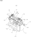
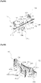
- FIGS. 1 to 8B are views illustrating an apparatus for manufacturing a cell stack for a secondary battery according to the present disclosure.
- an apparatus 100 for manufacturing a cell stack for a secondary battery includes; a stack table 130 on which a negative electrode plate N (see FIGS. 8A and 8B ) and a positive electrode plate P (see FIGS. 8A and 8B ), which are continuously supplied from a negative electrode plate delivering picker 20 (see FIGS. 8A and 8B ) and a positive electrode plate delivering picker 30 (see FIGS. 8A and 8B ), respectively, are sequentially stacked with a separator S (see FIGS.
- an electrode-plate-stacking-position adjusting means 140 configured to adjust a position of the stack table 130 so that the negative electrode plate N and the positive electrode plate P are stacked at a constant position (height) regardless of the number of times of stacking the negative electrode plate N and the positive electrode plate P which are to be stacked;
- a clamping means 150 configured to press, toward the stack table 130, edge portions of the negative electrode plate N, the positive electrode plate P, and the separator S, which are stacked on the stack table 130, and to clamp the edge portions of the negative electrode plate N, the positive electrode plate P, and the separator S; and a drive means 120 configured to reciprocally turn the stack table 130, the electrode-plate-stacking-position adjusting means 140, and the clamping means 150 to both sides so that the separator S supplied to the stack table 130 is folded in a zigzag shape and the negative electrode plates N and the positive electrode plates P are alternately stacked between folded portions of the separator S folded in the zig
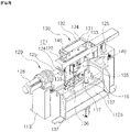
- the apparatus 100 for manufacturing a cell stack for a secondary battery further includes a support means 110 configured to support the stack table 130, the electrode-plate-stacking-position adjusting means 140, the clamping means 150, and the drive means 120.
- the support means 110 includes a base 111, and first and second support frames 112a and 112b formed on an upper surface of the base 111.
- the first and second support frames 112a and 112b extend in a longitudinal direction of the base 111 and extend vertically outward from the upper surface of the base 111. In this case, as illustrated, the first and second support frames 112a and 112b are spaced apart from each other at a predetermined interval.
- the support means 110 further includes a mounting frame 113 disposed between the first and second support frames 112a and 112b, and a mounting frame lifting servo motor 115 configured to raise or lower the mounting frame 113.
- the mounting frame 113 extends in the longitudinal direction of the base 111 and extends vertically outward from the upper surface of the base 111.
- the mounting frame 113 configured as described above, is disposed between the first and second support frames 112a and 112b so as to be movable upward and downward.
- mounting frame lifting LM guides 114a are installed and vertically extend at both sides, i.e., one end and the other end of the mounting frame 113, respectively, and mounting frame lifting LM guide blocks 114b are installed on inner surfaces of the first and second support frames 112a and 112b so as to be slidably fitted with the mounting frame lifting LM guides 114a.
- first and second support frames 112a and 112b and a central portion of the mounting frame 113 are recessed so that the first and second support frames 112a and 112b and the mounting frame 113 do not interfere with the stack table 130, the electrode-plate-stacking-position adjusting means 140, and the clamping means 150 which are reciprocally turned to both sides by the drive means 120 supported on the mounting frame 113.
- the mounting frame 113 has an approximately U-shaped cross section.
- the mounting frame lifting servo motor 115 is installed on a lower surface of the base 111, and a rotating shaft of the mounting frame lifting servo motor 115 penetrates the base 111 and vertically extends.
- a mounting frame lifting ball screw 116 is vertically connected, by means of a typical coupling, to the rotating shaft of the mounting frame lifting servo motor 115 which penetrates the base 111.
- mounting frame lifting ball screw 116 vertically penetrates a lower portion of the mounting frame 113, and a mounting frame lifting ball screw nut 117, which is engaged with and penetrated by the mounting frame lifting ball screw 116, is installed on the lower portion of the mounting frame 113.
- the mounting frame lifting servo motor 115 which is disposed as described above, rotates the mounting frame lifting ball screw 116 forward to raise the mounting frame 113, and the mounting frame 113, which is raised as described above, guides the manufactured (completely stacked) cell stack to an unloading position.
- the mounting frame lifting servo motor 115 rotates the mounting frame lifting ball screw 116 reversely to lower the mounting frame 113.
- the drive means 120 includes a tilting frame 121 on which the stack table 130, the electrode-plate-stacking-position adjusting means 140, and the clamping means 150 are mounted, and a tilting servo motor 126 configured to reciprocally turn the tilting frame 121 to both sides of the mounting frame 113.
- the tilting frame 121 includes a head part 122 disposed at the recessed central portion of the mounting frame 113 and horizontally extending in a longitudinal direction of the mounting frame 113, and a skirt part 124 formed integrally on a lower surface of the head part 122.
- both ends of the head part 122 further horizontally extend outward from both ends of the skirt part 124.
- Tilting shafts 125 are mounted at both ends of the head part 122 configured as described above, and the tilting shafts 125 horizontally extend to an upper portion at one end and an upper portion at the other end of the mounting frame 113 which are adjacent to each other.
- extension ends of the tilting shafts 125 which extend to the upper portion at one end and the upper portion at the other end of the mounting frame 113, are rotatably supported on the upper portion at one end and the upper portion at the other end of the mounting frame 113, respectively.
- the tilting servo motor 126 is installed on the upper portion at one end of the mounting frame 113 on which the tilting shaft 125 is rotatably supported, or the tilting servo motor 126 is installed on each of the upper portion at one end and the upper portion at the other end of the mounting frame 112.
- a rotating shaft of the tilting servo motor 126 which is installed on the upper portion at one end of the mounting frame 113 or installed on each of the upper portion at one end and the upper portion at the other end of the mounting frame 112, is connected, by means of a speed reducer, to the tilting shaft 125 adjacent to the rotating shaft of the tilting servo motor 126.
- the tilting servo motor 126 which is connected to the tilting shaft 125 as described above, reciprocally turns the tilting shaft 125 and the tilting frame 121 to both sides of the mounting frame 113 at a predetermined angle during the process of manufacturing a cell stack. Therefore, the stack table 130, the electrode-plate-stacking-position adjusting means 140, and the clamping means 150, which are mounted on the tilting frame 121, are also reciprocally turned, along with the tilting frame 121, to both sides of the mounting frame 113 at the predetermined angle.
- the tilting servo motor 126 rotates the tilting shafts 125 to allow the tilting frame 121 to stand vertically, thereby guiding the manufactured cell stack to the unloading position.
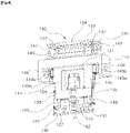
- the stack table 130 includes a suction table 131 and a lift table 134 which are disposed to be spaced apart from an upper side of the head part 122 of the tilting frame 121.
- the suction table 131 has an approximately "]" shape when viewed in a plan view, and multiple vacuum suction holes 132 are formed on the upper surface of the suction table 131 in accordance with a shape of the suction table 131.
- the vacuum suction holes 132 are connected to a typical vacuum tube (not illustrated), and the vacuum suction holes 132 are supplied with vacuum pressure through the vacuum tube, thereby fixing a tip of the separator S supplied to the upper portion of the suction table 131.
- a cell stack unloading means (not illustrated) configured to hold the completely manufactured cell stack and transfer the cell stack to a subsequent process enters or exits an opening portion 133 formed in the suction table 131.
- the lift table 134 is provided to occupy the inside of the suction table 131 when viewed in a plan view, and the lift table 134, together with the suction table 131, defines a stacking surface on which the negative electrode plate N and the positive electrode plate P may be sequentially stacked with the separator S interposed therebetween.
- the lift table 134 is raised or lowered so that the cell stack unloading means (not illustrated) may easily hold the completely manufactured cell stack.
- the stack table 130 further include lift table lifting cylinders 135 configured to raise or lower the lift table 134.
- the lift table lifting cylinders 135 are installed at both ends of a second lift plate 144 of the electrode-plate-stacking-position adjusting means 140 to be described below, and cylinder rods of the lift table lifting cylinders 135 extend outward from a lower portion of the second lift plate 144.
- first lift plate 136 disposed horizontally outside the lower portion of the second lift plate 144.
- first lift plate 136 and the lift table 134 are connected by means of first connecting rods 137.
- the first connecting rods 137 extend from the first lift plate 136, penetrate the second lift plate 144 of the electrode-plate-stacking-position adjusting means 140 disposed between the first lift plate 136 and the skirt part 124, penetrate the skirt part 124, penetrate the head part 122, and penetrate a third lift plate 146 of the electrode-plate-stacking-position adjusting means 140 disposed between the head part 122 and the lift table 134, and then the first connecting rods 137 are connected to a lower portion of the lift table 134.
- the tilting servo motor 126 of the drive means 120 stands the tilting frame 121 vertically, and the mounting frame lifting servo motor 115 of the support means 110 raises the mounting frame 113, thereby guiding the completely manufactured cell stack to the unloading position.
- the opening portion 133 of the suction table 131 faces the cell stack unloading means (not illustrated) .
- the cylinder rods of the lift table lifting cylinders 135 are extended to lower the first lift plate 136.
- the lift table 134 which is connected to the first lift plate 136 by means of the first connecting rods 137, is lowered together with the first lift plate 136.
- the lift table lifting cylinders 135 retract the extended cylinder rods, such that the first lift plate 136 and the lift table 134 are also returned while being raised.
- the electrode-plate-stacking-position adjusting means 140 includes a stacking position adjusting servo motor 141 configured to adjust the position of the stack table 130 so that the negative electrode plate N and the positive electrode plate P are stacked at a constant position (height) with the separator S interposed therebetween during the process of manufacturing a cell stack.
- the stacking position adjusting servo motor 141 is installed on a bottom of a hollow portion 127 formed in the skirt part 124 of the tilting frame 121, and a stacking position adjusting ball screw 142 is vertically connected, by means of a typical coupling, to a rotating shaft of the stacking position adjusting servo motor 141.
- the stacking position adjusting ball screw 142 extends while vertically penetrating the skirt part 124, vertically penetrating the second lift plate 144 disposed between the lower portion of the skirt part 124 and the first lift plate 136, and vertically penetrating the first lift plate 136.
- a stacking position adjusting ball screw nut 143 which is engaged with and penetrated by the stacking position adjusting ball screw 142, is installed on the second lift plate 144.
- the second lift plate 144 is connected, by means of second connecting rods 145, to the third lift plate 146 that supports the stack table 130.
- the third lift plate 146 is horizontally disposed between the head part 122 of the tilting frame 121 and the stack table 130 so as to support the stack table 130.
- the suction table 131 of the stack table 130 which faces an upper surface of the third lift plate 146 adjacent to both ends of the third lift plate 146, is connected to the third lift plate 146 by means of leg members 147.
- extension brackets 148 vertically extend from a lower surface of the third lift plate 146 which is connected to both ends of the third lift plate 146, and the extension brackets 148 slidably and vertically penetrate the head part 122 of the tilting frame 121 and face both ends of the skirt part 124.
- stacking position adjusting LM guides 149a are installed so as not to interfere with the lift table lifting cylinders 135, and the stacking position adjusting LM guides 149a are installed at both ends of the skirt part 124 which face the extension brackets 148.
- the stacking position adjusting LM guides 149a are installed vertically in a longitudinal direction of the skirt part 124.
- Stacking position adjusting LM guide blocks 149b which are slidably fitted with the stacking position adjusting LM guides 149a, are installed on the extension brackets 148.
- the stacking position adjusting servo motor 141 rotates the stacking position adjusting ball screw 142 forward by a length corresponding to a thickness of the stacked negative electrode plate N or the stacked positive electrode plate P in order to lower the second lift plate 144 to the extent corresponding to the thickness of the negative electrode plate N or the positive electrode plate P.
- the third lift plate 146 which is connected to the second lift plate 144 by means of the second connecting rods 145, and the suction table 131 of the stack table 130, which is connected to the third lift plate 146 by means of the leg members 147, are also lowered to the extent corresponding to the thickness of the stacked negative electrode plate N or the stacked positive electrode plate P. Therefore, during the process of manufacturing a cell stack, the negative electrode plate N or the positive electrode plate P is stacked on the separator S at a constant position (height) regardless of the number of times of stacking the negative electrode plate N and the positive electrode plate P to be stacked.
- the stacking position adjusting servo motor 141 rotates the stacking position adjusting ball screw 142 reversely to return the second and third lift plates 144 and 146 and the stack table 130.
- the clamping means 150 includes four gripper assemblies 162 disposed at both ends at one side and both ends at the other side of the stack table 130, and first and second gripper moving units 159a and 159b configured to allow the two gripper assemblies 162, which face each other in a longitudinal direction of the stack table 130, to cooperate with each other, and to move the two gripper assemblies 162 so that the two gripper assemblies 162, which cooperate with each other, alternately press edges at one side and the other side of each of the separator S, the negative electrode plate N, and the positive electrode plate P which are stacked on the stack table 130.
- the clamping means 150 further includes first and second clamping frames 151a and 151b configured to support the first and second gripper moving units 159a and 159b, respectively, and first and second gripper lifting units 155a and 155b configured to raise or lower the first and second clamping frames 151a and 151b, respectively, to allow the gripper assemblies 162 to alternately press the edges at one side and the other side of each of the separator S, the negative electrode plate N, and the positive electrode plate P which are stacked on the stack table 130.
- first and second clamping frames 151a and 151b horizontally extend in the longitudinal direction of the mounting frame 113.
- First and second gripper assembly moving LM guides 152a and 152b are installed on outer surfaces of the first and second clamping frames 151a and 151b, respectively.
- first and second clamping frames 151a and 151b are mounted to be movable upward and downward at one side and the other side of the skirt part 124 of the tilting frame 121, respectively.
- first and second gripper assembly lifting LM guides 153a and 153b are installed vertically in the longitudinal direction of the skirt part 124 at one side and the other side of the skirt part 124, and first and second gripper assembly lifting LM guide blocks 154a and 154b, which are slidably fitted with the first and second gripper assembly lifting LM guides 153a and 153b, are installed on inner surfaces of the first and second clamping frames 151a and 151b which face the first and second gripper assembly lifting LM guides 153a and 153b, respectively.
- first and second gripper assembly lifting LM guides 153a and 153b installed at one side and the other side of the skirt part 124 are installed at one side and the other side of the skirt part 124, by means of first and second support plates 177a and 177b installed at one side and the other side of the skirt part 124, so as not to interfere with the stacking position adjusting servo motor 141.
- first and second gripper lifting units 155a and 155b include first and second gripper assembly lifting servo motors 156a and 156b disposed at lower sides of outer surfaces of the first and second clamping frames 151a and 151b, respectively, and first and second gripper assembly lifting ball screws 157a and 157b configured to rotate by being connected, by typical power transmission means, to rotating shafts of the first and second gripper assembly lifting servo motors 156a and 156b.
- Each of the first and second gripper assembly lifting ball screws 157a and 157b is disposed vertically between each of the first and second clamping frames 151a and 151b and each of first and second support plates 177a and 177b adjacent to each of the first and second gripper assembly lifting servo motors 156a and 156b that interacts with each of the first and second gripper assembly lifting ball screws 157a and 157b.
- first and second gripper assembly lifting ball screws 157a and 157b are rotatably supported at lower sides of the first and second support plates 177a and 177b that extend outward from lower portions of the first and second clamping frames 151a and 151b adjacent to lower portions of the first and second support plates 177a and 177b.
- First and second gripper assembly lifting ball screw nuts 158a and 158b which are engaged with and penetrated by the first and second gripper assembly lifting ball screws 157a and 157b, are installed on inner surfaces of the first and second clamping frames 151a and 151b.
- first and second gripper assembly lifting servo motors 156a and 156b which interact with the first and second gripper assembly lifting ball screws 157a and 157b, are also installed at the lower sides of the first and second support plates 177a and 177b.
- Each of the first and second support plates 177a and 177b has an approximately "L" shape when viewed from the lateral side.
- the typical power transmission means which connect the first and second gripper assembly lifting servo motors 156a and 156b and the first and second gripper assembly lifting ball screws 157a and 157b, may be timing belt pulleys and timing belts. Because the connection relationships, using the timing belt pulleys and the timing belts, between the first and second gripper assembly lifting servo motors 156a and 156b and the first and second gripper assembly lifting ball screws 157a and 157b are publicly known technologies, a detailed description thereof will be omitted.
- the first and second gripper assembly lifting servo motors 156a and 156b of the first and second gripper lifting units 155a and 155b configured as described above raise or lower the first and second clamping frames 151a and 151b so that the gripper assemblies 162 may alternately press the edges at one side and the other side of each of the separator S, the negative electrode plate N, and the positive electrode plate P which are stacked on the stack table 130.
- the first and second gripper assembly lifting servo motors 156a and 156b of the first and second gripper lifting units 155a and 155b rotate the first and second gripper assembly lifting ball screws 157a and 157b forward to raise the first and second clamping frames 151a and 151b.
- the gripper assemblies 162, which press and restrict the completely manufactured cell stack are raised together with the first and second clamping frames 151a and 151b, such that the cell stack unloading means may unload the completely manufactured cell stack to the outside.
- the first and second gripper assembly lifting servo motors 156a and 156b rotate the first and second gripper assembly lifting ball screws 157a and 157b reversely to lower the first and second clamping frames 151a and 151b.
- the gripper assemblies 162 are also lowered and returned together with the first and second clamping frames 151a and 151b.
- the first gripper moving unit 159a includes a pair of gripper assembly moving servo motors 160a installed at both ends of a lower portion of the first clamping frame 151a, and a pair of gripper assembly moving ball screws 161a rotatably supported on an upper portion of the first clamping frame 151a and extending horizontally in a longitudinal direction of the first clamping frame 151a so as not to interfere with each other at the upper portion of the first clamping frame 151a.
- the second gripper moving unit 159b includes a pair of gripper assembly moving servo motors 160b installed at both ends of a lower portion of the second clamping frame 151b, and a pair of gripper assembly moving ball screws 161b rotatably supported on an upper portion of the second clamping frame 151b and extending horizontally in a longitudinal direction of the second clamping frame 151b so as not to interfere with each other at the upper portion of the second clamping frame 151b.
- any one of the pair of gripper assembly moving ball screws 161a provided on the upper portion of the first clamping frame 151a horizontally extends from one end of the upper portion of the first clamping frame 151a to a central portion of the first clamping frame 151a
- the other of the pair of gripper assembly moving ball screws 161a horizontally extends from the other end of the upper portion of the first clamping frame 151a to the central portion of the first clamping frame 151a.
- any one of the pair of gripper assembly moving ball screws 161a provided on the upper portion of the first clamping frame 151a is connected, by a typical power transmission means, to a rotating shaft of one gripper assembly moving servo motor 160a adjacent to one gripper assembly moving ball screw 161a, and the other gripper assembly moving ball screw 161a connected, by a typical power transmission means, to the other gripper assembly moving servo motor 160a adjacent to the other gripper assembly moving ball screw 161a.
- any one of the pair of gripper assembly moving ball screws 161b provided on the upper portion of the second clamping frame 151b horizontally extends from one end of the upper portion of the second clamping frame 151b to a central portion of the second clamping frame 151b
- the other of the pair of gripper assembly moving ball screws 161b horizontally extends from the other end of the upper portion of the second clamping frame 151b to the central portion of the clamping frame 151b.
- any one of the pair of gripper assembly moving ball screws 161b provided on the upper portion of the second clamping frame 151b is connected, by a typical power transmission means, to a rotating shaft of one gripper assembly moving servo motor 160b adjacent to one gripper assembly moving ball screw 161b, and the other gripper assembly moving ball screw 161b is connected, by a typical power transmission means, to the other gripper assembly moving servo motor 160b adjacent to the other gripper assembly moving ball screw 161b.
- screw threads of the pair of gripper assembly moving ball screws 161a provided on the upper portion of the first clamping frame 151a extend in opposite directions.
- screw threads of the pair of gripper assembly moving ball screws 161b provided on the upper portion of the second clamping frame 151b extend in opposite directions.
- the first gripper moving unit 159a includes the two gripper assembly moving servo motors 160a and the two gripper assembly moving ball screws 161a
- the second gripper moving unit 159b includes the two gripper assembly moving servo motors 160b and the two gripper assembly moving ball screws 161b.
- each of the first and second gripper moving units 159a and 159b may include a single gripper assembly moving servo motor, and a single gripper moving ball screw having screw threads formed in opposite directions from a central portion to respective ends.
- the four gripper assemblies 162 have an identical configuration and an identical shape.
- Each of the gripper assemblies 162 includes a slider 163, and a gripper 164 mounted on the slider 163.
- the two gripper assemblies 162 configured as described above make up one set so as to face each other and are connected to the first gripper moving unit 159a and the second gripper moving unit 159b.
- the slider 163 of any one gripper assembly 162, which is connected to the first gripper moving unit 159a, is connected to any one gripper assembly moving ball screw 161a of the first gripper moving unit 159a
- the slider 163 of the other gripper assembly 162, which is connected to the first gripper moving unit 159a is connected to the other gripper assembly moving ball screw 161a of the first gripper moving unit 159a.
- any one gripper assembly 162, which is connected to the second gripper moving unit 159b is connected to any one gripper assembly moving ball screw 161b of the second gripper moving unit 159b
- the slider 163 of the other gripper assembly 162, which is connected to the second gripper moving unit 159b is connected to the other gripper assembly moving ball screw 161b of the second gripper moving unit 159b.
- gripper assembly moving ball screw nuts 165 which are engaged with the gripper assembly moving ball screws 161a and 161b of the first and second gripper moving units 159a and 159b, are installed on lower portions of the sliders 163 of the gripper assemblies 162, respectively.
- gripper assembly moving LM guide blocks 175, which are slidably fitted with the first gripper assembly moving LM guide 152a formed on the outer surface of the first clamping frame 151a, are installed on the sliders 163 of the gripper assemblies 162, respectively, which are connected to any one gripper assembly moving ball screw 161a and the other gripper assembly moving ball screw 161a of the first gripper moving unit 159a, respectively.
- gripper assembly moving LM guide blocks 175, which are slidably fitted with the second gripper assembly moving LM guide 152b formed on the outer surface of the second clamping frame 151b, are installed on the sliders 163 of the gripper assemblies 162, respectively, which are connected to any one gripper assembly moving ball screw 161b and the other gripper assembly moving ball screw 161b of the second gripper moving unit 159b, respectively.
- the two gripper assemblies 162, which are connected to the first gripper moving unit 159a as described above, are moved in the directions toward or away from both ends at one side of the stack table 130 by the operations of the gripper assembly moving servo motors 160a, and similarly, the two gripper assemblies 162, which are connected to the second gripper moving unit 159b, are moved in the directions toward or away from both ends at the other side of the stack table 130 by the operations of the gripper assembly moving servo motors 160b.
- the gripper 164 which is mounted on the slider 163 of each of the gripper assemblies 162, has a horizontally extending bar shape.
- the gripper 164 is mounted on an actuator 176 such as a typical pneumatic cylinder or a typical linear motor so as to be movable upward and downward.
- variable block 166 having a vertical plate shape.
- the variable block 166 is coupled and supported, by means of screws 174, onto a rear surface of a fixed block 167 fixedly mounted on the slider 163.
- the grippers 164 which are supported on the sliders 163 as described above, are raised and then lowered by the operations of the first and second gripper assembly lifting servo motors 156a and 156b of the first and second gripper lifting units 155a and 155b, thereby pressing and fixing the edges at one side and the other side of each of the separator S, the negative electrode plate N, and the positive electrode plate P.
- the grippers 164 are mounted on the sliders 163 so that reference positions of the grippers 164 may be finely adjusted in left, right, up, and down directions.
- a first fixing piece 168 is protrudingly mounted at one side of the fixed block 167, and a first variable piece 169, which vertically faces the first fixing piece 168, is protrudingly mounted on a front surface of the variable block 166 which faces the first fixing piece 168.
- a first fine adjustment bolt 170 having a threaded portion having an end fastened to the first variable piece 169 is fitted with the first fixing piece 168.
- a second fixing piece 171 which extends horizontally while penetrating the variable block 166, is mounted at the other side of the fixed block 167, and a second variable piece 172, which faces the second fixing piece 171 in the left-right direction, is protrudingly mounted on a rear surface of the variable block 166.
- a second fine adjustment bolt 173 having a threaded portion having an end fastened to the second fixing piece 171 is fitted with the second variable piece 172.
- an operation of finely adjusting the reference position of each of the grippers 164 is performed by slightly loosening the screws 174, which are configured to couple and support the variable block 166 to the fixed block 167, so that the variable block 166 may be moved, and then loosening or tightening the first and second fine adjustment bolts 170 and 173.
- the screws 174 are fully fastened again, such that the variable block 166 is coupled to and supported on the fixed block 167.
- a tip of the separator S supplied from a separator supply unit 10 is fixed onto the suction table 131 of the stack table 130.
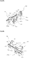
- the drive means 120 operates the tilting servo motor 126 to turn the tilting shaft 125 toward a negative electrode plate delivering picker 20 first in order to fold the separator S in a zigzag shape and alternately stack the negative electrode plate N and the positive electrode plate P between the folded portions of the separator S (see FIG. 8A ).
- the tilting frame 121 mounted on the tilting shaft 125 is also turned toward the negative electrode plate delivering picker 20.
- the stack table 130, the electrode-plate-stacking-position adjusting means 140, and the clamping means 150, which are mounted on the tilting frame 121 are also turned toward the negative electrode plate delivering picker 20, and the stack table 130 onto which the separator S is fixed faces the negative electrode plate delivering picker 20.
- the negative electrode plate delivering picker 20 places the sucked negative electrode plate N on the separator S fixed onto the stack table 130 and then moves upward (see FIG. 8A ).
- the clamping means 150 moves the two gripper assemblies 162, supported on second clamping frame 151b, toward the stack table 130 so that the two gripper assemblies 162 are adjacent to the stack table 130.
- the grippers 164 mounted on the gripper assemblies 162 are raised and then lowered by the operation of the second gripper assembly lifting servo motor 156b of the second gripper lifting unit 155b, thereby pressing and fixing, toward the stack table 130, the edges at both ends of the other side of the negative electrode plate N placed on the separator S (see FIG. 8A ).
- the electrode-plate-stacking-position adjusting means 140 operates the stacking position adjusting servo motor 141 to lower the stack table 130 to the extent corresponding to the thickness of the negative electrode plate N placed on the separator S (see FIG. 8A ).
- the tilting servo motor 126 turns the tilting shaft 125 toward a positive electrode plate delivering picker 30(see FIG. 8B ).
- the tilting frame 121 mounted on the tilting shaft 125 is also turned toward the positive electrode plate delivering picker 30.
- the stack table 130, the electrode-plate-stacking-position adjusting means 140, and the clamping means 150 which are mounted on the tilting frame 121, are also turned toward the positive electrode plate delivering picker 30, and the stack table 130 onto which the separator S is fixed faces the positive electrode plate delivering picker 30.
- the separator S supplied from the separator supply unit 10 covers an upper portion of the negative electrode plate N stacked on the stack table 130 (see FIG. 8B ).
- the positive electrode plate delivering picker 30 places the sucked positive electrode plate P on the separator S which covers the negative electrode plate N, and then the positive electrode plate delivering picker 30 moves upward (see FIG. 8B ) .
- the clamping means 150 moves the two gripper assemblies 162, supported on the first clamping frame 151a, toward the stack table 130 so that the two gripper assemblies 162 are adjacent to the stack table 130.
- the grippers 164 mounted on the two gripper assemblies 162 are raised and then lowered by the operation of the first gripper assembly lifting servo motor 156a of the first gripper lifting unit 155a, thereby pressing and fixing, toward the stack table 130, the edges at both ends of one side of the positive electrode plate P placed on the separator S.
- the two gripper assemblies 162 of the second clamping frame 151b which press and fix the edges at both ends of the other side of the negative electrode plate N, are moved away from the stack table 130, thereby releasing the edges at both ends of the other side of the negative electrode plate N (see FIG. 8B ).
- the electrode-plate-stacking-position adjusting means 140 operates the stacking position adjusting servo motor 141 to lower the stack table 130 to the extent corresponding to the thickness of the positive electrode plate P placed on the separator S (see FIG. 8B ).
- the tilting servo motor 126 turns the tilting shaft 125 again toward the negative electrode plate delivering picker 20.
- the stack table 130 faces the negative electrode plate delivering picker 20 again.
- the grippers 164 of the gripper assemblies 162 supported on the first clamping frame 151a press and fix one end of the positive electrode plate P stacked on the stack table 130
- the separator S supplied from the separator supply unit 10 covers an upper portion of the positive electrode plate P stacked on the stack table 130, and the negative electrode plate N is placed and fixed again onto the separator S that covers the positive electrode plate P, as illustrated in FIG. 8A .
- the negative electrode plates N and the positive electrode plates P are stacked with the separators S interposed therebetween.
- the tilting servo motor 126 rotates the tilting shaft 125 to stand the tilting frame 121 and the stack table 130 vertically in order to unload the completely manufactured cell stack.
- the support means 110 operates the mounting frame lifting servo motor 115 to raise the mounting frame 113 so that the completely manufactured cell stack is guided to the unloading position.
- the suction table 131 of the stack table 130 faces the cell stack unloading means (not illustrated).
- the cell stack unloading means moves toward the opening portion 133 of the suction table 131 in order to hold the completely manufactured cell stack.
- the lift table lifting cylinders 135 of the stack table 130 extend the cylinder rods to lower the lift table 134.
- the lift table lifting cylinders 135 retract the lift table 134.
- the mounting frame lifting servo motor 115 returns the mounting frame 113 to prepare for a subsequent process.
- the apparatus 100 for manufacturing a cell stack for a secondary battery configured as described above, it is possible to change the height of the stack table 130 in accordance with the number of times of stacking the negative electrode plate N and the positive electrode plate P during a process of manufacturing a cell stack, and as a result, it is possible to always maintain a constant position (height) at which the negative electrode plate N and the positive electrode plate P are stacked. Accordingly, it is possible to solve the problem, in the related art, that the separator S is torn or damaged during the process of manufacturing a cell stack.
- the separator is torn or damaged during the process of manufacturing a cell stack.
Landscapes
- Engineering & Computer Science (AREA)
- Manufacturing & Machinery (AREA)
- Chemical & Material Sciences (AREA)
- Chemical Kinetics & Catalysis (AREA)
- Electrochemistry (AREA)
- General Chemical & Material Sciences (AREA)
- Secondary Cells (AREA)
Applications Claiming Priority (1)
| Application Number | Priority Date | Filing Date | Title |
|---|---|---|---|
| KR1020200021754A KR102120403B1 (ko) | 2020-02-21 | 2020-02-21 | 이차전지용 셀 스택 제조장치 |
Publications (2)
| Publication Number | Publication Date |
|---|---|
| EP3869602A1 EP3869602A1 (en) | 2021-08-25 |
| EP3869602B1 true EP3869602B1 (en) | 2022-07-06 |
Family
ID=71089984
Family Applications (1)
| Application Number | Title | Priority Date | Filing Date |
|---|---|---|---|
| EP20186242.2A Active EP3869602B1 (en) | 2020-02-21 | 2020-07-16 | Apparatus for manufacturing cell stack for secondary battery |
Country Status (6)
| Country | Link |
|---|---|
| US (1) | US11522211B2 (pl) |
| EP (1) | EP3869602B1 (pl) |
| KR (1) | KR102120403B1 (pl) |
| CN (2) | CN113299965B (pl) |
| HU (1) | HUE059931T2 (pl) |
| PL (1) | PL3869602T3 (pl) |
Families Citing this family (36)
| Publication number | Priority date | Publication date | Assignee | Title |
|---|---|---|---|---|
| KR102120403B1 (ko) * | 2020-02-21 | 2020-06-08 | 주식회사 우원기술 | 이차전지용 셀 스택 제조장치 |
| CN111883854A (zh) * | 2020-08-03 | 2020-11-03 | 东莞市超鸿自动化设备有限公司 | 一种锂电池极片高速叠片台 |
| KR102900630B1 (ko) * | 2020-12-04 | 2025-12-15 | 주식회사 엘지에너지솔루션 | 전극 조립체의 스태킹 장치 및 스태킹 방법 |
| KR102320868B1 (ko) * | 2020-12-21 | 2021-11-03 | 주식회사 우원기술 | 이차전지용 셀 스택 제조장치 |
| KR102333754B1 (ko) * | 2020-12-31 | 2021-12-01 | (주)엔에스 | 전극조립체 제조장치의 스윙 모듈 |
| KR102513329B1 (ko) * | 2021-01-13 | 2023-03-24 | 주식회사 에스에이치엘 | 곡선과 직선 경로를 이용한 2차전지용 전극 및 분리막 적층 방법 및 장치 |
| KR102505146B1 (ko) * | 2021-03-04 | 2023-03-02 | 주식회사 클레버 | 파우치형 이차전지 테이핑 장치용 테이프 가접유닛 |
| KR102505155B1 (ko) * | 2021-03-04 | 2023-03-02 | 주식회사 클레버 | 파우치형 이차전지 테이핑 장치용 테이프 가접유닛 |
| KR102319133B1 (ko) * | 2021-04-12 | 2021-10-29 | (주)엔에스 | 분리막 인출장치 |
| CN113224424A (zh) * | 2021-04-26 | 2021-08-06 | 衢州广泰环保技术服务有限公司 | 一种铝塑膜包膜贴胶系统 |
| KR102608771B1 (ko) * | 2021-06-21 | 2023-12-01 | 주식회사 엠플러스 | 라미네이팅 및 제트 폴딩 스택 시스템 및 라미네이팅 및 제트 폴딩 스택 방법 |
| KR102606211B1 (ko) * | 2021-06-21 | 2023-11-29 | 주식회사 엠플러스 | 위치 가변 피앤피 유닛과 가이드 롤러 요동 운동에 의한 전지용 극판 적층 시스템 및 극판 적층 방법 |
| KR102595123B1 (ko) * | 2021-06-21 | 2023-10-27 | 주식회사 엠플러스 | 이차전지 극판과 분리막 동시 적층장치 |
| KR102589113B1 (ko) * | 2021-06-21 | 2023-10-13 | 주식회사 엠플러스 | 2장의 극판과 분리막을 고속 적층할 수 있는 스택 테이블 구조 및 적층방법 |
| KR102606431B1 (ko) * | 2021-06-24 | 2023-11-29 | 주식회사 에스에프에이 | 이차전지 고속 셀 스태킹장치 |
| KR102586960B1 (ko) * | 2021-06-28 | 2023-10-11 | 주식회사 디에이테크놀로지 | 이차전지 전극조립체의 단면 전극 스택용 분리막 핸들링장치 및 이를 이용한 이차전지 전극조립체 제조 방법 |
| KR102606432B1 (ko) * | 2021-06-29 | 2023-11-29 | 주식회사 에스에프에이 | 적층 셀 풀링장치 및 그를 구비하는 이차전지 고속 셀 스태킹시스템 |
| KR102405964B1 (ko) | 2021-09-16 | 2022-06-08 | 주식회사 신룡 | 이차전지용 셀 스택 제조장치 및 셀 스택 제조방법 |
| KR102404678B1 (ko) | 2021-10-18 | 2022-06-02 | 주식회사 우원기술 | 셀 스택 제조용 분리막 공급피더 |
| KR102404675B1 (ko) | 2021-12-09 | 2022-06-02 | 주식회사 우원기술 | 이차전지의 셀 스택 제조장치용 맨드릴 유닛 |
| KR102755489B1 (ko) | 2022-03-17 | 2025-01-21 | 주식회사 디에이테크놀로지 | 이차전지의 스윙형 셀 스택 제조장치 |
| CN115172844B (zh) * | 2022-07-06 | 2025-03-11 | 中创新航科技集团股份有限公司 | 电池堆叠设备及堆叠方法 |
| CN115241510B (zh) * | 2022-08-18 | 2023-04-07 | 佛山市天劲新能源科技有限公司 | 一种电芯堆叠处理装置及其操作方法 |
| KR20240048668A (ko) * | 2022-10-07 | 2024-04-16 | 현대자동차주식회사 | 전극의 이매 취출 방지 장치 |
| KR20240102428A (ko) * | 2022-12-26 | 2024-07-03 | 주식회사 엘지에너지솔루션 | 전극 공급 장치, 이를 이용하는 전극 조립체 제조 장치, 전극 공급 방법 및 이를 이용하는 전극 조립체 제조 방법 |
| CN116014211B (zh) * | 2022-12-29 | 2026-03-17 | 广东凯乐仕佳的科技有限公司 | 外置动力源电池极片堆叠装置 |
| KR102884936B1 (ko) | 2023-07-13 | 2025-11-12 | 주식회사 원익피앤이 | 이차전지 셀 스택 제조장치용 맨드릴 조립체 |
| KR20250122666A (ko) | 2024-02-07 | 2025-08-14 | 주식회사 에스이 | 이차전지용 셀 공급장치 |
| KR102728779B1 (ko) | 2024-02-13 | 2024-11-13 | 주식회사 우원기술 | 이차전지 셀 스택 제조 장치용 클램핑 유닛 |
| KR20250127841A (ko) | 2024-02-20 | 2025-08-27 | 주식회사 에스이 | 이차전지용 셀 공급장치 |
| KR102708257B1 (ko) | 2024-03-05 | 2024-09-23 | 주식회사 우원기술 | 분리막 본딩 브러쉬 장치 |
| CN118492628B (zh) * | 2024-07-18 | 2024-10-11 | 深圳市荣利伟业科技有限公司 | 一种锂电池的焊接装置 |
| KR20260017658A (ko) | 2024-07-30 | 2026-02-06 | 주식회사 에스이 | 이차전지용 셀 공급장치 |
| CN119890390B (zh) * | 2025-01-14 | 2025-08-08 | 扬州天运电力发展有限公司 | 一种锂电池智能组装装配设备及方法 |
| US12476270B1 (en) * | 2025-04-18 | 2025-11-18 | Woowon Technology Co., Ltd. | Apparatus for manufacturing a cell stack for a secondary battery having clamping unit |
| CN121307126A (zh) * | 2025-10-14 | 2026-01-09 | 台州东孚新能源有限公司 | 一种电芯装入支架自动安装设备 |
Family Cites Families (13)
| Publication number | Priority date | Publication date | Assignee | Title |
|---|---|---|---|---|
| KR100313119B1 (ko) | 1999-01-26 | 2001-11-03 | 김순택 | 이차전지의 전극군 |
| JP3794632B2 (ja) * | 2002-06-19 | 2006-07-05 | 東レエンジニアリング株式会社 | 電池製造機 |
| KR101140447B1 (ko) | 2007-09-19 | 2012-04-30 | 에스케이이노베이션 주식회사 | 이차전지용 스택 제조장치 |
| US8574320B2 (en) * | 2009-06-08 | 2013-11-05 | GM Global Technology Operations LLC | Press apparatus |
| KR101730469B1 (ko) | 2015-12-21 | 2017-04-27 | 주식회사 디에이테크놀로지 | 이차전지의 고속 셀 스택 제조장치 |
| CN108461797B (zh) * | 2017-02-17 | 2021-01-22 | Da技术有限公司 | 二次电池的高速电池堆制造装置 |
| KR101933550B1 (ko) * | 2017-09-28 | 2018-12-31 | 주식회사 디에이테크놀로지 | 이차전지의 셀 스택 제조 시스템 |
| KR101956758B1 (ko) * | 2017-10-23 | 2019-03-11 | 주식회사 디에이테크놀로지 | 이차전지의 셀 스택 제조장치 |
| KR102003728B1 (ko) * | 2018-02-13 | 2019-10-01 | 주식회사 이노메트리 | 각형 이차전지용 고속 스택 제조 장치 |
| KR101959082B1 (ko) * | 2018-09-07 | 2019-03-18 | 조기봉 | 이차전지의 셀 스택 고속 제조장치 |
| KR102043902B1 (ko) * | 2019-06-07 | 2019-11-12 | (주)호명이엔지 | 이차전지용 전극적층장치 |
| JP6888654B2 (ja) * | 2019-08-23 | 2021-06-16 | トヨタ自動車株式会社 | 積層体保持装置 |
| KR102120403B1 (ko) * | 2020-02-21 | 2020-06-08 | 주식회사 우원기술 | 이차전지용 셀 스택 제조장치 |
-
2020
- 2020-02-21 KR KR1020200021754A patent/KR102120403B1/ko active Active
- 2020-07-14 US US16/928,536 patent/US11522211B2/en active Active
- 2020-07-16 PL PL20186242.2T patent/PL3869602T3/pl unknown
- 2020-07-16 EP EP20186242.2A patent/EP3869602B1/en active Active
- 2020-07-16 HU HUE20186242A patent/HUE059931T2/hu unknown
- 2020-11-05 CN CN202011221735.9A patent/CN113299965B/zh active Active
- 2020-11-05 CN CN202022539961.3U patent/CN214672717U/zh not_active Withdrawn - After Issue
Also Published As
| Publication number | Publication date |
|---|---|
| US11522211B2 (en) | 2022-12-06 |
| PL3869602T3 (pl) | 2022-11-21 |
| CN113299965B (zh) | 2025-04-18 |
| CN113299965A (zh) | 2021-08-24 |
| US20210265650A1 (en) | 2021-08-26 |
| EP3869602A1 (en) | 2021-08-25 |
| HUE059931T2 (hu) | 2023-01-28 |
| CN214672717U (zh) | 2021-11-09 |
| KR102120403B1 (ko) | 2020-06-08 |
Similar Documents
| Publication | Publication Date | Title |
|---|---|---|
| EP3869602B1 (en) | Apparatus for manufacturing cell stack for secondary battery | |
| KR102320868B1 (ko) | 이차전지용 셀 스택 제조장치 | |
| KR102303834B1 (ko) | 이차전지의 고속 셀 스택 제조장치 | |
| CN109585898B (zh) | 二次电池的电池组制造系统 | |
| KR102676855B1 (ko) | 이차전지의 셀 스택 제조장치 | |
| KR102256378B1 (ko) | 이차전지의 셀 스택 제조 시스템 및 방법 | |
| KR101959082B1 (ko) | 이차전지의 셀 스택 고속 제조장치 | |
| KR101140447B1 (ko) | 이차전지용 스택 제조장치 | |
| KR102755489B1 (ko) | 이차전지의 스윙형 셀 스택 제조장치 | |
| US9401576B2 (en) | Apparatus and method for manufacturing a stacked electrode | |
| CN110212236B (zh) | 一种锂离子电池高速叠片方法 | |
| CN114024017A (zh) | 连续往复移动叠片机构及叠片方法 | |
| KR20200139983A (ko) | 2차 전지용 연속식 고속 셀 스택 전극 클램프장치 | |
| KR20220022197A (ko) | 이차 전지용 셀 스택 제조 장치 | |
| EP4418378A1 (en) | Electrode plate loading device for secondary battery | |
| CN216105162U (zh) | 一种多段式张力控制的激光切割辊压一体机 | |
| KR20220022200A (ko) | 노칭 기능이 구비된 이차 전지용 셀 스택 제조 장치 | |
| KR102165376B1 (ko) | 2차 전지용 연속식 고속 셀 스택 적층장치 | |
| CN113602878A (zh) | 一种张力控制方法及极片激光切割辊压一体机 | |
| KR20220169706A (ko) | 위치 가변 피앤피 유닛과 가이드 롤러 요동 운동에 의한 전지용 극판 적층 시스템 및 극판 적층 방법 | |
| CN108461797B (zh) | 二次电池的高速电池堆制造装置 | |
| EP4391127A1 (en) | Secondary cell stacking apparatus | |
| CN216597697U (zh) | 立式叠片机及电芯制造设备 | |
| CN215680746U (zh) | 一种叠片装置 | |
| CN216266447U (zh) | 自动裁切装置 |
Legal Events
| Date | Code | Title | Description |
|---|---|---|---|
| PUAI | Public reference made under article 153(3) epc to a published international application that has entered the european phase |
Free format text: ORIGINAL CODE: 0009012 |
|
| STAA | Information on the status of an ep patent application or granted ep patent |
Free format text: STATUS: REQUEST FOR EXAMINATION WAS MADE |
|
| 17P | Request for examination filed |
Effective date: 20200716 |
|
| AK | Designated contracting states |
Kind code of ref document: A1 Designated state(s): AL AT BE BG CH CY CZ DE DK EE ES FI FR GB GR HR HU IE IS IT LI LT LU LV MC MK MT NL NO PL PT RO RS SE SI SK SM TR |
|
| GRAP | Despatch of communication of intention to grant a patent |
Free format text: ORIGINAL CODE: EPIDOSNIGR1 |
|
| STAA | Information on the status of an ep patent application or granted ep patent |
Free format text: STATUS: GRANT OF PATENT IS INTENDED |
|
| INTG | Intention to grant announced |
Effective date: 20220325 |
|
| GRAS | Grant fee paid |
Free format text: ORIGINAL CODE: EPIDOSNIGR3 |
|
| GRAA | (expected) grant |
Free format text: ORIGINAL CODE: 0009210 |
|
| STAA | Information on the status of an ep patent application or granted ep patent |
Free format text: STATUS: THE PATENT HAS BEEN GRANTED |
|
| AK | Designated contracting states |
Kind code of ref document: B1 Designated state(s): AL AT BE BG CH CY CZ DE DK EE ES FI FR GB GR HR HU IE IS IT LI LT LU LV MC MK MT NL NO PL PT RO RS SE SI SK SM TR |
|
| REG | Reference to a national code |
Ref country code: AT Ref legal event code: REF Ref document number: 1503517 Country of ref document: AT Kind code of ref document: T Effective date: 20220715 Ref country code: CH Ref legal event code: EP |
|
| REG | Reference to a national code |
Ref country code: DE Ref legal event code: R096 Ref document number: 602020003858 Country of ref document: DE |
|
| REG | Reference to a national code |
Ref country code: IE Ref legal event code: FG4D |
|
| REG | Reference to a national code |
Ref country code: SE Ref legal event code: TRGR |
|
| REG | Reference to a national code |
Ref country code: LT Ref legal event code: MG9D |
|
| REG | Reference to a national code |
Ref country code: NL Ref legal event code: MP Effective date: 20220706 |
|
| REG | Reference to a national code |
Ref country code: HU Ref legal event code: AG4A Ref document number: E059931 Country of ref document: HU |
|
| PG25 | Lapsed in a contracting state [announced via postgrant information from national office to epo] |
Ref country code: RS Free format text: LAPSE BECAUSE OF FAILURE TO SUBMIT A TRANSLATION OF THE DESCRIPTION OR TO PAY THE FEE WITHIN THE PRESCRIBED TIME-LIMIT Effective date: 20220706 Ref country code: PT Free format text: LAPSE BECAUSE OF FAILURE TO SUBMIT A TRANSLATION OF THE DESCRIPTION OR TO PAY THE FEE WITHIN THE PRESCRIBED TIME-LIMIT Effective date: 20221107 Ref country code: NO Free format text: LAPSE BECAUSE OF FAILURE TO SUBMIT A TRANSLATION OF THE DESCRIPTION OR TO PAY THE FEE WITHIN THE PRESCRIBED TIME-LIMIT Effective date: 20221006 Ref country code: NL Free format text: LAPSE BECAUSE OF FAILURE TO SUBMIT A TRANSLATION OF THE DESCRIPTION OR TO PAY THE FEE WITHIN THE PRESCRIBED TIME-LIMIT Effective date: 20220706 Ref country code: LV Free format text: LAPSE BECAUSE OF FAILURE TO SUBMIT A TRANSLATION OF THE DESCRIPTION OR TO PAY THE FEE WITHIN THE PRESCRIBED TIME-LIMIT Effective date: 20220706 Ref country code: LT Free format text: LAPSE BECAUSE OF FAILURE TO SUBMIT A TRANSLATION OF THE DESCRIPTION OR TO PAY THE FEE WITHIN THE PRESCRIBED TIME-LIMIT Effective date: 20220706 Ref country code: FI Free format text: LAPSE BECAUSE OF FAILURE TO SUBMIT A TRANSLATION OF THE DESCRIPTION OR TO PAY THE FEE WITHIN THE PRESCRIBED TIME-LIMIT Effective date: 20220706 Ref country code: ES Free format text: LAPSE BECAUSE OF FAILURE TO SUBMIT A TRANSLATION OF THE DESCRIPTION OR TO PAY THE FEE WITHIN THE PRESCRIBED TIME-LIMIT Effective date: 20220706 |
|
| REG | Reference to a national code |
Ref country code: DE Ref legal event code: R119 Ref document number: 602020003858 Country of ref document: DE |
|
| REG | Reference to a national code |
Ref country code: AT Ref legal event code: MK05 Ref document number: 1503517 Country of ref document: AT Kind code of ref document: T Effective date: 20220706 |
|
| PG25 | Lapsed in a contracting state [announced via postgrant information from national office to epo] |
Ref country code: IS Free format text: LAPSE BECAUSE OF FAILURE TO SUBMIT A TRANSLATION OF THE DESCRIPTION OR TO PAY THE FEE WITHIN THE PRESCRIBED TIME-LIMIT Effective date: 20221106 Ref country code: HR Free format text: LAPSE BECAUSE OF FAILURE TO SUBMIT A TRANSLATION OF THE DESCRIPTION OR TO PAY THE FEE WITHIN THE PRESCRIBED TIME-LIMIT Effective date: 20220706 Ref country code: GR Free format text: LAPSE BECAUSE OF FAILURE TO SUBMIT A TRANSLATION OF THE DESCRIPTION OR TO PAY THE FEE WITHIN THE PRESCRIBED TIME-LIMIT Effective date: 20221007 |
|
| REG | Reference to a national code |
Ref country code: BE Ref legal event code: MM Effective date: 20220731 |
|
| PG25 | Lapsed in a contracting state [announced via postgrant information from national office to epo] |
Ref country code: SM Free format text: LAPSE BECAUSE OF FAILURE TO SUBMIT A TRANSLATION OF THE DESCRIPTION OR TO PAY THE FEE WITHIN THE PRESCRIBED TIME-LIMIT Effective date: 20220706 Ref country code: RO Free format text: LAPSE BECAUSE OF FAILURE TO SUBMIT A TRANSLATION OF THE DESCRIPTION OR TO PAY THE FEE WITHIN THE PRESCRIBED TIME-LIMIT Effective date: 20220706 Ref country code: MC Free format text: LAPSE BECAUSE OF FAILURE TO SUBMIT A TRANSLATION OF THE DESCRIPTION OR TO PAY THE FEE WITHIN THE PRESCRIBED TIME-LIMIT Effective date: 20220706 Ref country code: LU Free format text: LAPSE BECAUSE OF NON-PAYMENT OF DUE FEES Effective date: 20220716 Ref country code: DK Free format text: LAPSE BECAUSE OF FAILURE TO SUBMIT A TRANSLATION OF THE DESCRIPTION OR TO PAY THE FEE WITHIN THE PRESCRIBED TIME-LIMIT Effective date: 20220706 Ref country code: CZ Free format text: LAPSE BECAUSE OF FAILURE TO SUBMIT A TRANSLATION OF THE DESCRIPTION OR TO PAY THE FEE WITHIN THE PRESCRIBED TIME-LIMIT Effective date: 20220706 Ref country code: AT Free format text: LAPSE BECAUSE OF FAILURE TO SUBMIT A TRANSLATION OF THE DESCRIPTION OR TO PAY THE FEE WITHIN THE PRESCRIBED TIME-LIMIT Effective date: 20220706 |
|
| PLBE | No opposition filed within time limit |
Free format text: ORIGINAL CODE: 0009261 |
|
| STAA | Information on the status of an ep patent application or granted ep patent |
Free format text: STATUS: NO OPPOSITION FILED WITHIN TIME LIMIT |
|
| PG25 | Lapsed in a contracting state [announced via postgrant information from national office to epo] |
Ref country code: SK Free format text: LAPSE BECAUSE OF FAILURE TO SUBMIT A TRANSLATION OF THE DESCRIPTION OR TO PAY THE FEE WITHIN THE PRESCRIBED TIME-LIMIT Effective date: 20220706 Ref country code: EE Free format text: LAPSE BECAUSE OF FAILURE TO SUBMIT A TRANSLATION OF THE DESCRIPTION OR TO PAY THE FEE WITHIN THE PRESCRIBED TIME-LIMIT Effective date: 20220706 Ref country code: DE Free format text: LAPSE BECAUSE OF NON-PAYMENT OF DUE FEES Effective date: 20230201 Ref country code: BE Free format text: LAPSE BECAUSE OF NON-PAYMENT OF DUE FEES Effective date: 20220731 |
|
| 26N | No opposition filed |
Effective date: 20230411 |
|
| PG25 | Lapsed in a contracting state [announced via postgrant information from national office to epo] |
Ref country code: AL Free format text: LAPSE BECAUSE OF FAILURE TO SUBMIT A TRANSLATION OF THE DESCRIPTION OR TO PAY THE FEE WITHIN THE PRESCRIBED TIME-LIMIT Effective date: 20220706 |
|
| PG25 | Lapsed in a contracting state [announced via postgrant information from national office to epo] |
Ref country code: IE Free format text: LAPSE BECAUSE OF NON-PAYMENT OF DUE FEES Effective date: 20220716 Ref country code: FR Free format text: LAPSE BECAUSE OF NON-PAYMENT OF DUE FEES Effective date: 20220906 |
|
| PG25 | Lapsed in a contracting state [announced via postgrant information from national office to epo] |
Ref country code: SI Free format text: LAPSE BECAUSE OF FAILURE TO SUBMIT A TRANSLATION OF THE DESCRIPTION OR TO PAY THE FEE WITHIN THE PRESCRIBED TIME-LIMIT Effective date: 20220706 |
|
| PG25 | Lapsed in a contracting state [announced via postgrant information from national office to epo] |
Ref country code: IT Free format text: LAPSE BECAUSE OF FAILURE TO SUBMIT A TRANSLATION OF THE DESCRIPTION OR TO PAY THE FEE WITHIN THE PRESCRIBED TIME-LIMIT Effective date: 20220706 |
|
| REG | Reference to a national code |
Ref country code: CH Ref legal event code: PL |
|
| PG25 | Lapsed in a contracting state [announced via postgrant information from national office to epo] |
Ref country code: MK Free format text: LAPSE BECAUSE OF FAILURE TO SUBMIT A TRANSLATION OF THE DESCRIPTION OR TO PAY THE FEE WITHIN THE PRESCRIBED TIME-LIMIT Effective date: 20220706 Ref country code: CY Free format text: LAPSE BECAUSE OF FAILURE TO SUBMIT A TRANSLATION OF THE DESCRIPTION OR TO PAY THE FEE WITHIN THE PRESCRIBED TIME-LIMIT Effective date: 20220706 Ref country code: CH Free format text: LAPSE BECAUSE OF NON-PAYMENT OF DUE FEES Effective date: 20230731 |
|
| PG25 | Lapsed in a contracting state [announced via postgrant information from national office to epo] |
Ref country code: TR Free format text: LAPSE BECAUSE OF FAILURE TO SUBMIT A TRANSLATION OF THE DESCRIPTION OR TO PAY THE FEE WITHIN THE PRESCRIBED TIME-LIMIT Effective date: 20220706 |
|
| PG25 | Lapsed in a contracting state [announced via postgrant information from national office to epo] |
Ref country code: BG Free format text: LAPSE BECAUSE OF FAILURE TO SUBMIT A TRANSLATION OF THE DESCRIPTION OR TO PAY THE FEE WITHIN THE PRESCRIBED TIME-LIMIT Effective date: 20220706 |
|
| PG25 | Lapsed in a contracting state [announced via postgrant information from national office to epo] |
Ref country code: MT Free format text: LAPSE BECAUSE OF FAILURE TO SUBMIT A TRANSLATION OF THE DESCRIPTION OR TO PAY THE FEE WITHIN THE PRESCRIBED TIME-LIMIT Effective date: 20220706 |
|
| GBPC | Gb: european patent ceased through non-payment of renewal fee |
Effective date: 20240716 |
|
| PG25 | Lapsed in a contracting state [announced via postgrant information from national office to epo] |
Ref country code: GB Free format text: LAPSE BECAUSE OF NON-PAYMENT OF DUE FEES Effective date: 20240716 |
|
| PGFP | Annual fee paid to national office [announced via postgrant information from national office to epo] |
Ref country code: HU Payment date: 20250807 Year of fee payment: 6 |
|
| PGFP | Annual fee paid to national office [announced via postgrant information from national office to epo] |
Ref country code: PL Payment date: 20250801 Year of fee payment: 6 |
|
| PGFP | Annual fee paid to national office [announced via postgrant information from national office to epo] |
Ref country code: SE Payment date: 20250723 Year of fee payment: 6 |