EP3868632B1 - Transferwagen - Google Patents
Transferwagen Download PDFInfo
- Publication number
- EP3868632B1 EP3868632B1 EP21157742.4A EP21157742A EP3868632B1 EP 3868632 B1 EP3868632 B1 EP 3868632B1 EP 21157742 A EP21157742 A EP 21157742A EP 3868632 B1 EP3868632 B1 EP 3868632B1
- Authority
- EP
- European Patent Office
- Prior art keywords
- transfer
- transfer carriage
- medium
- carriage
- open
- Prior art date
- Legal status (The legal status is an assumption and is not a legal conclusion. Google has not performed a legal analysis and makes no representation as to the accuracy of the status listed.)
- Active
Links
Images

Classifications
-
- B—PERFORMING OPERATIONS; TRANSPORTING
- B62—LAND VEHICLES FOR TRAVELLING OTHERWISE THAN ON RAILS
- B62B—HAND-PROPELLED VEHICLES, e.g. HAND CARTS OR PERAMBULATORS; SLEDGES
- B62B3/00—Hand carts having more than one axis carrying transport wheels; Steering devices therefor; Equipment therefor
-
- B—PERFORMING OPERATIONS; TRANSPORTING
- B62—LAND VEHICLES FOR TRAVELLING OTHERWISE THAN ON RAILS
- B62B—HAND-PROPELLED VEHICLES, e.g. HAND CARTS OR PERAMBULATORS; SLEDGES
- B62B3/00—Hand carts having more than one axis carrying transport wheels; Steering devices therefor; Equipment therefor
- B62B3/04—Hand carts having more than one axis carrying transport wheels; Steering devices therefor; Equipment therefor involving means for grappling or securing in place objects to be carried; Loading or unloading equipment
- B62B3/06—Hand carts having more than one axis carrying transport wheels; Steering devices therefor; Equipment therefor involving means for grappling or securing in place objects to be carried; Loading or unloading equipment for simply clearing the load from the ground
- B62B3/0618—Hand carts having more than one axis carrying transport wheels; Steering devices therefor; Equipment therefor involving means for grappling or securing in place objects to be carried; Loading or unloading equipment for simply clearing the load from the ground using fluid lifting mechanisms
-
- B—PERFORMING OPERATIONS; TRANSPORTING
- B62—LAND VEHICLES FOR TRAVELLING OTHERWISE THAN ON RAILS
- B62B—HAND-PROPELLED VEHICLES, e.g. HAND CARTS OR PERAMBULATORS; SLEDGES
- B62B3/00—Hand carts having more than one axis carrying transport wheels; Steering devices therefor; Equipment therefor
- B62B3/04—Hand carts having more than one axis carrying transport wheels; Steering devices therefor; Equipment therefor involving means for grappling or securing in place objects to be carried; Loading or unloading equipment
- B62B3/06—Hand carts having more than one axis carrying transport wheels; Steering devices therefor; Equipment therefor involving means for grappling or securing in place objects to be carried; Loading or unloading equipment for simply clearing the load from the ground
-
- B—PERFORMING OPERATIONS; TRANSPORTING
- B62—LAND VEHICLES FOR TRAVELLING OTHERWISE THAN ON RAILS
- B62B—HAND-PROPELLED VEHICLES, e.g. HAND CARTS OR PERAMBULATORS; SLEDGES
- B62B5/00—Accessories or details specially adapted for hand carts
-
- B—PERFORMING OPERATIONS; TRANSPORTING
- B62—LAND VEHICLES FOR TRAVELLING OTHERWISE THAN ON RAILS
- B62B—HAND-PROPELLED VEHICLES, e.g. HAND CARTS OR PERAMBULATORS; SLEDGES
- B62B5/00—Accessories or details specially adapted for hand carts
- B62B5/0083—Wheeled supports connected to the transported object
- B62B5/0093—Flat dollys without hand moving equipment
-
- B—PERFORMING OPERATIONS; TRANSPORTING
- B66—HOISTING; LIFTING; HAULING
- B66F—HOISTING, LIFTING, HAULING OR PUSHING, NOT OTHERWISE PROVIDED FOR, e.g. DEVICES WHICH APPLY A LIFTING OR PUSHING FORCE DIRECTLY TO THE SURFACE OF A LOAD
- B66F3/00—Devices, e.g. jacks, adapted for uninterrupted lifting of loads
- B66F3/24—Devices, e.g. jacks, adapted for uninterrupted lifting of loads fluid-pressure operated
- B66F3/25—Constructional features
- B66F3/35—Inflatable flexible elements, e.g. bellows
Definitions
- the invention relates to a transfer carriage comprising side-by-side parallel longitudinal transfer units arranged to be movable and each of the transfer units comprises an outer beam and an inner beam which is arranged inside the outer beam.
- IT RM20080539 discloses a pneumatic lifting and handling device comprising wheels.
- the device comprises a first box that opens upwards.
- the first box has a first flat base and side edges demarcating the base.
- a second box which opens downwards and has a second flat base and side edges demarcating the base, is placed inside the first box.
- a pin inside a vertical slit limits the vertical movement of the boxes in respect of each other.
- DE 202014006562 discloses a conveyor unit for conveying loaded or unloaded charge carriers.
- DE 3638506 discloses a chassis for a movable grandstand.
- US 3019930 discloses a fork lift unit for lifting and moving heavy objects.
- the transfer carriage according to the invention is used to load containers, in particular.
- a transfer carriage is an excellent tool in particular for loading containers that open at their ends, in which case a load needs to be loaded into a narrow and long space.
- a transfer carriage may be used for loading from a side.
- a transfer carriage may also be used in connection with loading something else than containers, such as for loading a lorry or a trailer.
- An advantage of the inventive transfer carriage is that it may be easily moved under a load to be loaded or unloaded, and away. Loading and unloading become easier and faster with the transfer carriage, whereby major cost savings are achieved. Since the transfer unit of a transfer carriage has successive members, adjustable in the vertical direction by means of a medium, the adjustment may be efficiently carried out with a small amount of the medium, whereby a relatively low-capacity source for the medium may be used.
- a further advantage of the transfer carriage is that there is no need to carry it along with a container, but the loading and unloading ends may have their own transfer carriages. This way the entire volume of a container may be utilized to pack items being transported. Alternatively, the transfer carriage may be carried with the load.
- the transfer carriage is described in the position where it is when used on a horizontal surface.
- the longitudinal direction of the transfer carriage is the longitudinal direction of the outer and inner beam.
- a vertical direction refers to a surface orthogonal to the horizontal surface.
- the transfer carriage comprises side-by-side parallel longitudinal transfer units arranged to be movable and each comprising an outer beam and an inner beam which is arranged inside the outer beam.
- the transfer carriage is arranged movable by means of wheels, rolls, or similar.
- the wheels or rolls are usually in pairs so that there is one on both sides of the transfer carriage.
- One of the beams is a rectangular hollow beam, open at the top
- the other of the beams is a rectangular hollow beam, open at the bottom.
- the inner beam may be open at the top when the outer beam is open at the bottom
- the inner beam may be open at the bottom when the outer beam is open at the top.
- the open rectangular beam may be a so-called U-beam.
- the inner and outer beam are opposite each other so that an encased space is formed between them, where the required actuators may be placed.
- the outer beam and inner beam are connected by a limiter allowing vertical movement.
- the outer and inner beam may only move in the vertical direction in relation to each other.
- the movement limiter may be so arranged that the vertical walls of the beams are joined with an axle that exist through an opening in a side wall of the inner beam and a vertical groove in a side wall of the outer beam.
- the transfer unit also features a channel for a medium.
- the channel for a medium may be integrated as part of the beam.
- the channel for a medium is primarily intended for compressed air, but a hydraulic fluid may also be applied.
- Such members include, for example, air bellows that ascend or descend in the vertical direction according to whether more compressed air is led to the channel for a medium or whether it is reduced from the channel for a medium.
- Air bellows usually have 1, 2, or 3 bellows.
- An air bellows usually has a flange on both the upper and lower side. A first flange is attached to a beam surface over it, and a second flange is attached to a beam surface below it.
- the bellows itself is a ring-shaped cushion which may be made of fibre-reinforced rubber.
- a plurality of transfer units may be joined side-by-side so that the transfer units are arranged in parallel and interconnected through openings at the end of the transfer units, by using a rod.
- the interconnected transfer units are easy to move by pushing or pulling with a forklift, for example. It is also feasible to connect a plurality of transfer units successively.
- the air needed for the air bellows may be obtained from the compressor of the transfer means present during loading, in other words, a separate source is not necessarily needed for compressed air but the source for compressed air available at any one time may be utilised.
- the transfer carriage functions so that it is pushed, as lowered down, below the piece to be lifted. Next, compressed air is hooked up, resulting in that the members, such as air bellows, adjustable in the vertical direction raise the transfer carriage to the upper position. After this, the piece is easy to move due to the wheels that the transfers carriage has.
- the use of the transfer carriage for loading a container facilitates easy and fast loading in connection with long pieces, such as aluminium profiles, in particular.
- the long pieces are first placed on a suitably-sized load platform such as a loading pallet intended for transferring long pieces, which has the required space under it for the transfer carriage.
- the pieces are tied to the load platform and one or more transfer units are pushed under the load platform.
- the transfer units are connected together through the openings at the ends of the transfer units with a rod.
- the rod may also connect to the load platform under the pieces, if the load platform is provided with suitable openings.
- the load platform is raised by introducing air into the vertically-adjustable members of the transfer carriage, such as air bellows. Now, the load platform loaded with long pieces may be pushed inside a container. When the load platform is in place, the transfer carriage is lowered and removed from below the load platform.
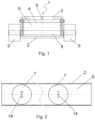
- Figure 1 shows a transfer unit 1 as seen from the ends of an outer beam 2 and inner beam 3. Between the outer beam 2 and inner beam 3, a space 6 is formed in which vertically adjustable members 7 (shown in Figure 2 ) are installed.
- the transfer unit 1 has wheels or rolls 9 interconnected by an axle 8. Furthermore, the transfers unit has a channel 5 for a medium integrated into the inner beam 3.
- FIG. 2 shows an opened transfer unit 1 from above.
- the vertically adjustable members 7 may be, for example, air bellows that ascend or descend in the vertical direction according to whether more compressed air is led to the channel for a medium or whether it is reduced from the channel for a medium.
- Air bellows usually have 1, 2, or 3 bellows.
- Figure 3 is a side view of the inner beam 3.
- the inner beam 3 has a space 10 for wheels or rolls 9, a lead-through 11 for a limiter 4 that allows vertical movement, and an opening 12 for joining the transfer units 1.
- Figure 4 is a side view of the transfer unit 1. Through the lead-through 11 in the inner beam 3 and through the groove 13 in the outer beam 2, the limiter 4 allowing vertical movement has been installed.
- the outer beam 2 has an opening 12 at the same place as in the inner beam 3 for interconnecting the transfer units 1.
Landscapes
- Engineering & Computer Science (AREA)
- Mechanical Engineering (AREA)
- Chemical & Material Sciences (AREA)
- Combustion & Propulsion (AREA)
- Transportation (AREA)
- Life Sciences & Earth Sciences (AREA)
- Geology (AREA)
- Structural Engineering (AREA)
- Handcart (AREA)
Claims (4)
- Transferwagen mit nebeneinander angeordneten, parallelen, längsgerichteten Transfereinheiten (1), die dafür eingerichtet sind, beweglich zu sein, und jede der Transfereinheiten (1) umfasst einen äußeren Träger (2) und einen inneren Träger (3), der zumindest teilweise innerhalb des äußeren Trägers (2) angeordnet ist, wobei- der erste der Träger (2, 3) ein rechteckiger, oben offener Hohlträger ist und der zweite der Träger ein rechteckiger, unten offener Hohlträger (2, 3) ist,- der äußere Träger (2) und der innere Träger (3) durch einen Begrenzer (4) verbunden sind, der eine vertikale Bewegung ermöglicht,- jede Transfereinheit (1) einen Kanal (5) für ein Medium aufweist, mit dem aufeinanderfolgende Elemente (7) verbunden sind, die mittels des Mediums in vertikaler Richtung verstellbar sind und in einem zwischen dem äußeren (2) und dem inneren Träger (3) gebildeten Raum (6) installiert sind,- jede Transfereinheit (1) eine Öffnung (12) am Ende der Transfereinheit (1) aufweist, und- die Transfereinheiten (1) an einem Ende durch die Öffnungen (12) hindurch durch eine Stange miteinander verbunden sind.
- Transferwagen nach Anspruch 1, dadurch gekennzeichnet , dass der erste Träger der äußere Träger (2) ist, der ein rechteckiger, oben offener Hohlträger ist, und der zweite Träger der innere Träger (3) ist, der ein rechteckiger, unten offener Hohlträger ist.
- Transferwagen nach Anspruch 1 oder 2, dadurch gekennzeichnet, dass die aufeinanderfolgenden vertikal verstellbaren Elemente (7) Luftbälge sind.
- Transferwagen nach einem der vorstehenden Ansprüche, dadurch gekennzeichnet, dass der Kanal (5) für ein Medium in den äußeren (2) oder inneren (3) Träger integriert ist.
Applications Claiming Priority (1)
| Application Number | Priority Date | Filing Date | Title |
|---|---|---|---|
| FI20205173A FI129355B (fi) | 2020-02-21 | 2020-02-21 | Siirtoalusta |
Publications (3)
| Publication Number | Publication Date |
|---|---|
| EP3868632A1 EP3868632A1 (de) | 2021-08-25 |
| EP3868632B1 true EP3868632B1 (de) | 2023-09-20 |
| EP3868632C0 EP3868632C0 (de) | 2023-09-20 |
Family
ID=74844667
Family Applications (1)
| Application Number | Title | Priority Date | Filing Date |
|---|---|---|---|
| EP21157742.4A Active EP3868632B1 (de) | 2020-02-21 | 2021-02-18 | Transferwagen |
Country Status (4)
| Country | Link |
|---|---|
| EP (1) | EP3868632B1 (de) |
| ES (1) | ES2961360T3 (de) |
| FI (1) | FI129355B (de) |
| PL (1) | PL3868632T3 (de) |
Families Citing this family (1)
| Publication number | Priority date | Publication date | Assignee | Title |
|---|---|---|---|---|
| CN114084219B (zh) * | 2021-11-29 | 2024-04-19 | 中国二十冶集团有限公司 | 一种电气设备运输装置及安装方法 |
Family Cites Families (4)
| Publication number | Priority date | Publication date | Assignee | Title |
|---|---|---|---|---|
| US3019930A (en) * | 1960-06-23 | 1962-02-06 | Stanray Corp | Fork lift unit |
| DE3638506C1 (de) * | 1986-11-11 | 1988-02-18 | Bayerische Buehnenbau Gmbh | Fahrwerk fuer eine verfahrbare Tribuene |
| ITRM20080539A1 (it) * | 2008-10-09 | 2010-04-10 | Angelo Trotta | Dispositivo pneumatico di sollevamento e movimentazione di oggetti, in particolare per oggetti di arredamento. |
| DE102013017062A1 (de) * | 2013-10-15 | 2015-04-16 | Eisenmann Ag | Fördereinheit und Fördersystem zum Fördern von Ladungsträgern |
-
2020
- 2020-02-21 FI FI20205173A patent/FI129355B/fi active IP Right Grant
-
2021
- 2021-02-18 EP EP21157742.4A patent/EP3868632B1/de active Active
- 2021-02-18 ES ES21157742T patent/ES2961360T3/es active Active
- 2021-02-18 PL PL21157742.4T patent/PL3868632T3/pl unknown
Also Published As
| Publication number | Publication date |
|---|---|
| FI129355B (fi) | 2021-12-31 |
| EP3868632A1 (de) | 2021-08-25 |
| EP3868632C0 (de) | 2023-09-20 |
| PL3868632T3 (pl) | 2024-02-26 |
| FI20205173A1 (fi) | 2021-08-22 |
| ES2961360T3 (es) | 2024-03-11 |
Similar Documents
| Publication | Publication Date | Title |
|---|---|---|
| US9950881B2 (en) | Robotic trailer loading device with telescoping robot | |
| CN205602717U (zh) | 袋装物料自动码垛装车系统 | |
| US9139406B2 (en) | Equipment for handling packs of tires | |
| EP0611245A2 (de) | Lastkraftwagen oder Anhänger für einen Lastkraftwagen | |
| US12319494B2 (en) | Container structure and associated assembly, method and adjustment mechanism | |
| CN110342271A (zh) | 一种全自动装卸物料agv及物料装卸方法 | |
| US4997335A (en) | Double drop trailer with lift and method of loading the same | |
| CN117088150B (zh) | 一种托盘垛装货物的自动装车设备及其控制方法 | |
| EP3868632B1 (de) | Transferwagen | |
| US20230192425A1 (en) | Apparatus and method for unloading and loading a transport unit | |
| KR20190057689A (ko) | 디팔렛타이저 | |
| CN111776771B (zh) | 一种集装箱货物装载系统及其装货方法 | |
| CN104016141A (zh) | 一种货物装卸装置 | |
| CN219859550U (zh) | 一种带托盘装车系统 | |
| FI127072B (fi) | Haalauspalkki, sen nostojärjestely ja kuljetin | |
| WO1999046195A1 (en) | Method and loading device for loading and unloading cargo space | |
| JP4541079B2 (ja) | 長尺物用パレットへの長尺物の積載方法並びに長尺物積載パレットの輸送容器への搬送方法 | |
| WO2006137542A1 (ja) | 搬送物搬送方法及びジャッキ具 | |
| CN113173242A (zh) | 一种货运无人机舱内货物运输装置及方法 | |
| JP3790670B2 (ja) | コンテナに対する積載物の搬入装置及び搬出装置並びに搬入方法及び搬出方法 | |
| CN116081338A (zh) | 两段式装车机和装车方法 | |
| KR100468193B1 (ko) | 화물차용 수평식 상,하역 장치 | |
| CN114890185B (zh) | 装卸货装置、自动化装卸搬运系统及其控制方法 | |
| CN105366317A (zh) | 一种物流自动上料系统 | |
| CN219949807U (zh) | 一种建筑材料码垛搬运提升机 |
Legal Events
| Date | Code | Title | Description |
|---|---|---|---|
| PUAI | Public reference made under article 153(3) epc to a published international application that has entered the european phase |
Free format text: ORIGINAL CODE: 0009012 |
|
| STAA | Information on the status of an ep patent application or granted ep patent |
Free format text: STATUS: THE APPLICATION HAS BEEN PUBLISHED |
|
| AK | Designated contracting states |
Kind code of ref document: A1 Designated state(s): AL AT BE BG CH CY CZ DE DK EE ES FI FR GB GR HR HU IE IS IT LI LT LU LV MC MK MT NL NO PL PT RO RS SE SI SK SM TR |
|
| STAA | Information on the status of an ep patent application or granted ep patent |
Free format text: STATUS: REQUEST FOR EXAMINATION WAS MADE |
|
| 17P | Request for examination filed |
Effective date: 20220225 |
|
| RBV | Designated contracting states (corrected) |
Designated state(s): AL AT BE BG CH CY CZ DE DK EE ES FI FR GB GR HR HU IE IS IT LI LT LU LV MC MK MT NL NO PL PT RO RS SE SI SK SM TR |
|
| GRAP | Despatch of communication of intention to grant a patent |
Free format text: ORIGINAL CODE: EPIDOSNIGR1 |
|
| STAA | Information on the status of an ep patent application or granted ep patent |
Free format text: STATUS: GRANT OF PATENT IS INTENDED |
|
| INTG | Intention to grant announced |
Effective date: 20230413 |
|
| GRAS | Grant fee paid |
Free format text: ORIGINAL CODE: EPIDOSNIGR3 |
|
| GRAA | (expected) grant |
Free format text: ORIGINAL CODE: 0009210 |
|
| STAA | Information on the status of an ep patent application or granted ep patent |
Free format text: STATUS: THE PATENT HAS BEEN GRANTED |
|
| AK | Designated contracting states |
Kind code of ref document: B1 Designated state(s): AL AT BE BG CH CY CZ DE DK EE ES FI FR GB GR HR HU IE IS IT LI LT LU LV MC MK MT NL NO PL PT RO RS SE SI SK SM TR |
|
| REG | Reference to a national code |
Ref country code: GB Ref legal event code: FG4D |
|
| REG | Reference to a national code |
Ref country code: CH Ref legal event code: EP |
|
| REG | Reference to a national code |
Ref country code: DE Ref legal event code: R096 Ref document number: 602021005202 Country of ref document: DE |
|
| REG | Reference to a national code |
Ref country code: IE Ref legal event code: FG4D |
|
| U01 | Request for unitary effect filed |
Effective date: 20231016 |
|
| U07 | Unitary effect registered |
Designated state(s): AT BE BG DE DK EE FI FR IT LT LU LV MT NL PT SE SI Effective date: 20231019 |
|
| PG25 | Lapsed in a contracting state [announced via postgrant information from national office to epo] |
Ref country code: GR Free format text: LAPSE BECAUSE OF FAILURE TO SUBMIT A TRANSLATION OF THE DESCRIPTION OR TO PAY THE FEE WITHIN THE PRESCRIBED TIME-LIMIT Effective date: 20231221 |
|
| PG25 | Lapsed in a contracting state [announced via postgrant information from national office to epo] |
Ref country code: RS Free format text: LAPSE BECAUSE OF FAILURE TO SUBMIT A TRANSLATION OF THE DESCRIPTION OR TO PAY THE FEE WITHIN THE PRESCRIBED TIME-LIMIT Effective date: 20230920 Ref country code: NO Free format text: LAPSE BECAUSE OF FAILURE TO SUBMIT A TRANSLATION OF THE DESCRIPTION OR TO PAY THE FEE WITHIN THE PRESCRIBED TIME-LIMIT Effective date: 20231220 Ref country code: HR Free format text: LAPSE BECAUSE OF FAILURE TO SUBMIT A TRANSLATION OF THE DESCRIPTION OR TO PAY THE FEE WITHIN THE PRESCRIBED TIME-LIMIT Effective date: 20230920 Ref country code: GR Free format text: LAPSE BECAUSE OF FAILURE TO SUBMIT A TRANSLATION OF THE DESCRIPTION OR TO PAY THE FEE WITHIN THE PRESCRIBED TIME-LIMIT Effective date: 20231221 |
|
| REG | Reference to a national code |
Ref country code: ES Ref legal event code: FG2A Ref document number: 2961360 Country of ref document: ES Kind code of ref document: T3 Effective date: 20240311 |
|
| U20 | Renewal fee for the european patent with unitary effect paid |
Year of fee payment: 4 Effective date: 20240213 |
|
| PG25 | Lapsed in a contracting state [announced via postgrant information from national office to epo] |
Ref country code: IS Free format text: LAPSE BECAUSE OF FAILURE TO SUBMIT A TRANSLATION OF THE DESCRIPTION OR TO PAY THE FEE WITHIN THE PRESCRIBED TIME-LIMIT Effective date: 20240120 |
|
| PG25 | Lapsed in a contracting state [announced via postgrant information from national office to epo] |
Ref country code: SM Free format text: LAPSE BECAUSE OF FAILURE TO SUBMIT A TRANSLATION OF THE DESCRIPTION OR TO PAY THE FEE WITHIN THE PRESCRIBED TIME-LIMIT Effective date: 20230920 Ref country code: RO Free format text: LAPSE BECAUSE OF FAILURE TO SUBMIT A TRANSLATION OF THE DESCRIPTION OR TO PAY THE FEE WITHIN THE PRESCRIBED TIME-LIMIT Effective date: 20230920 Ref country code: IS Free format text: LAPSE BECAUSE OF FAILURE TO SUBMIT A TRANSLATION OF THE DESCRIPTION OR TO PAY THE FEE WITHIN THE PRESCRIBED TIME-LIMIT Effective date: 20240120 Ref country code: CZ Free format text: LAPSE BECAUSE OF FAILURE TO SUBMIT A TRANSLATION OF THE DESCRIPTION OR TO PAY THE FEE WITHIN THE PRESCRIBED TIME-LIMIT Effective date: 20230920 Ref country code: SK Free format text: LAPSE BECAUSE OF FAILURE TO SUBMIT A TRANSLATION OF THE DESCRIPTION OR TO PAY THE FEE WITHIN THE PRESCRIBED TIME-LIMIT Effective date: 20230920 |
|
| REG | Reference to a national code |
Ref country code: DE Ref legal event code: R097 Ref document number: 602021005202 Country of ref document: DE |
|
| PLBE | No opposition filed within time limit |
Free format text: ORIGINAL CODE: 0009261 |
|
| STAA | Information on the status of an ep patent application or granted ep patent |
Free format text: STATUS: NO OPPOSITION FILED WITHIN TIME LIMIT |
|
| 26N | No opposition filed |
Effective date: 20240621 |
|
| PG25 | Lapsed in a contracting state [announced via postgrant information from national office to epo] |
Ref country code: MC Free format text: LAPSE BECAUSE OF FAILURE TO SUBMIT A TRANSLATION OF THE DESCRIPTION OR TO PAY THE FEE WITHIN THE PRESCRIBED TIME-LIMIT Effective date: 20230920 |
|
| REG | Reference to a national code |
Ref country code: CH Ref legal event code: PL |
|
| PG25 | Lapsed in a contracting state [announced via postgrant information from national office to epo] |
Ref country code: CH Free format text: LAPSE BECAUSE OF NON-PAYMENT OF DUE FEES Effective date: 20240229 |
|
| PG25 | Lapsed in a contracting state [announced via postgrant information from national office to epo] |
Ref country code: CH Free format text: LAPSE BECAUSE OF NON-PAYMENT OF DUE FEES Effective date: 20240229 |
|
| PG25 | Lapsed in a contracting state [announced via postgrant information from national office to epo] |
Ref country code: IE Free format text: LAPSE BECAUSE OF NON-PAYMENT OF DUE FEES Effective date: 20240218 |
|
| PG25 | Lapsed in a contracting state [announced via postgrant information from national office to epo] |
Ref country code: IE Free format text: LAPSE BECAUSE OF NON-PAYMENT OF DUE FEES Effective date: 20240218 |
|
| U20 | Renewal fee for the european patent with unitary effect paid |
Year of fee payment: 5 Effective date: 20250217 |
|
| PGFP | Annual fee paid to national office [announced via postgrant information from national office to epo] |
Ref country code: PL Payment date: 20250214 Year of fee payment: 5 |
|
| PGFP | Annual fee paid to national office [announced via postgrant information from national office to epo] |
Ref country code: ES Payment date: 20250512 Year of fee payment: 5 |
|
| PG25 | Lapsed in a contracting state [announced via postgrant information from national office to epo] |
Ref country code: CY Free format text: LAPSE BECAUSE OF FAILURE TO SUBMIT A TRANSLATION OF THE DESCRIPTION OR TO PAY THE FEE WITHIN THE PRESCRIBED TIME-LIMIT; INVALID AB INITIO Effective date: 20210218 |
|
| PG25 | Lapsed in a contracting state [announced via postgrant information from national office to epo] |
Ref country code: HU Free format text: LAPSE BECAUSE OF FAILURE TO SUBMIT A TRANSLATION OF THE DESCRIPTION OR TO PAY THE FEE WITHIN THE PRESCRIBED TIME-LIMIT; INVALID AB INITIO Effective date: 20210218 |
|
| GBPC | Gb: european patent ceased through non-payment of renewal fee |
Effective date: 20250218 |