EP3866518B1 - Verfahren zur steuerung der uplink-leistung, endgerätevorrichtung und netzwerkvorrichtung - Google Patents
Verfahren zur steuerung der uplink-leistung, endgerätevorrichtung und netzwerkvorrichtung Download PDFInfo
- Publication number
- EP3866518B1 EP3866518B1 EP19871790.2A EP19871790A EP3866518B1 EP 3866518 B1 EP3866518 B1 EP 3866518B1 EP 19871790 A EP19871790 A EP 19871790A EP 3866518 B1 EP3866518 B1 EP 3866518B1
- Authority
- EP
- European Patent Office
- Prior art keywords
- power
- terminal device
- uplink signal
- capability
- transmission
- Prior art date
- Legal status (The legal status is an assumption and is not a legal conclusion. Google has not performed a legal analysis and makes no representation as to the accuracy of the status listed.)
- Active
Links
Images

Classifications
-
- H—ELECTRICITY
- H04—ELECTRIC COMMUNICATION TECHNIQUE
- H04W—WIRELESS COMMUNICATION NETWORKS
- H04W52/00—Power management, e.g. Transmission Power Control [TPC] or power classes
- H04W52/04—Transmission power control [TPC]
- H04W52/06—TPC algorithms
- H04W52/14—Separate analysis of uplink or downlink
- H04W52/146—Uplink power control
-
- H—ELECTRICITY
- H04—ELECTRIC COMMUNICATION TECHNIQUE
- H04B—TRANSMISSION
- H04B7/00—Radio transmission systems, i.e. using radiation field
- H04B7/02—Diversity systems; Multi-antenna system, i.e. transmission or reception using multiple antennas
- H04B7/04—Diversity systems; Multi-antenna system, i.e. transmission or reception using multiple antennas using two or more spaced independent antennas
- H04B7/0404—Diversity systems; Multi-antenna system, i.e. transmission or reception using multiple antennas using two or more spaced independent antennas the mobile station comprising multiple antennas, e.g. to provide uplink diversity
-
- H—ELECTRICITY
- H04—ELECTRIC COMMUNICATION TECHNIQUE
- H04B—TRANSMISSION
- H04B7/00—Radio transmission systems, i.e. using radiation field
- H04B7/02—Diversity systems; Multi-antenna system, i.e. transmission or reception using multiple antennas
- H04B7/04—Diversity systems; Multi-antenna system, i.e. transmission or reception using multiple antennas using two or more spaced independent antennas
- H04B7/0413—MIMO systems
- H04B7/0426—Power distribution
-
- H—ELECTRICITY
- H04—ELECTRIC COMMUNICATION TECHNIQUE
- H04B—TRANSMISSION
- H04B7/00—Radio transmission systems, i.e. using radiation field
- H04B7/02—Diversity systems; Multi-antenna system, i.e. transmission or reception using multiple antennas
- H04B7/04—Diversity systems; Multi-antenna system, i.e. transmission or reception using multiple antennas using two or more spaced independent antennas
- H04B7/0413—MIMO systems
- H04B7/0456—Selection of precoding matrices or codebooks, e.g. using matrices antenna weighting
-
- H—ELECTRICITY
- H04—ELECTRIC COMMUNICATION TECHNIQUE
- H04L—TRANSMISSION OF DIGITAL INFORMATION, e.g. TELEGRAPHIC COMMUNICATION
- H04L5/00—Arrangements affording multiple use of the transmission path
- H04L5/003—Arrangements for allocating sub-channels of the transmission path
- H04L5/0053—Allocation of signalling, i.e. of overhead other than pilot signals
-
- H—ELECTRICITY
- H04—ELECTRIC COMMUNICATION TECHNIQUE
- H04W—WIRELESS COMMUNICATION NETWORKS
- H04W52/00—Power management, e.g. Transmission Power Control [TPC] or power classes
- H04W52/04—Transmission power control [TPC]
-
- H—ELECTRICITY
- H04—ELECTRIC COMMUNICATION TECHNIQUE
- H04W—WIRELESS COMMUNICATION NETWORKS
- H04W52/00—Power management, e.g. Transmission Power Control [TPC] or power classes
- H04W52/04—Transmission power control [TPC]
- H04W52/18—TPC being performed according to specific parameters
-
- H—ELECTRICITY
- H04—ELECTRIC COMMUNICATION TECHNIQUE
- H04W—WIRELESS COMMUNICATION NETWORKS
- H04W52/00—Power management, e.g. Transmission Power Control [TPC] or power classes
- H04W52/04—Transmission power control [TPC]
- H04W52/30—Transmission power control [TPC] using constraints in the total amount of available transmission power
- H04W52/36—Transmission power control [TPC] using constraints in the total amount of available transmission power with a discrete range or set of values, e.g. step size, ramping or offsets
- H04W52/367—Power values between minimum and maximum limits, e.g. dynamic range
-
- H—ELECTRICITY
- H04—ELECTRIC COMMUNICATION TECHNIQUE
- H04W—WIRELESS COMMUNICATION NETWORKS
- H04W52/00—Power management, e.g. Transmission Power Control [TPC] or power classes
- H04W52/04—Transmission power control [TPC]
- H04W52/38—TPC being performed in particular situations
- H04W52/42—TPC being performed in particular situations in systems with time, space, frequency or polarisation diversity
-
- H—ELECTRICITY
- H04—ELECTRIC COMMUNICATION TECHNIQUE
- H04W—WIRELESS COMMUNICATION NETWORKS
- H04W52/00—Power management, e.g. Transmission Power Control [TPC] or power classes
- H04W52/04—Transmission power control [TPC]
- H04W52/52—Transmission power control [TPC] using AGC [Automatic Gain Control] circuits or amplifiers
-
- H—ELECTRICITY
- H04—ELECTRIC COMMUNICATION TECHNIQUE
- H04W—WIRELESS COMMUNICATION NETWORKS
- H04W72/00—Local resource management
- H04W72/04—Wireless resource allocation
- H04W72/044—Wireless resource allocation based on the type of the allocated resource
- H04W72/0473—Wireless resource allocation based on the type of the allocated resource the resource being transmission power
-
- H—ELECTRICITY
- H04—ELECTRIC COMMUNICATION TECHNIQUE
- H04L—TRANSMISSION OF DIGITAL INFORMATION, e.g. TELEGRAPHIC COMMUNICATION
- H04L5/00—Arrangements affording multiple use of the transmission path
- H04L5/0001—Arrangements for dividing the transmission path
- H04L5/0014—Three-dimensional division
- H04L5/0023—Time-frequency-space
-
- H—ELECTRICITY
- H04—ELECTRIC COMMUNICATION TECHNIQUE
- H04L—TRANSMISSION OF DIGITAL INFORMATION, e.g. TELEGRAPHIC COMMUNICATION
- H04L5/00—Arrangements affording multiple use of the transmission path
- H04L5/003—Arrangements for allocating sub-channels of the transmission path
- H04L5/0048—Allocation of pilot signals, i.e. of signals known to the receiver
-
- H—ELECTRICITY
- H04—ELECTRIC COMMUNICATION TECHNIQUE
- H04L—TRANSMISSION OF DIGITAL INFORMATION, e.g. TELEGRAPHIC COMMUNICATION
- H04L5/00—Arrangements affording multiple use of the transmission path
- H04L5/0091—Signalling for the administration of the divided path, e.g. signalling of configuration information
- H04L5/0094—Indication of how sub-channels of the path are allocated
-
- H—ELECTRICITY
- H04—ELECTRIC COMMUNICATION TECHNIQUE
- H04W—WIRELESS COMMUNICATION NETWORKS
- H04W52/00—Power management, e.g. Transmission Power Control [TPC] or power classes
- H04W52/04—Transmission power control [TPC]
- H04W52/06—TPC algorithms
-
- H—ELECTRICITY
- H04—ELECTRIC COMMUNICATION TECHNIQUE
- H04W—WIRELESS COMMUNICATION NETWORKS
- H04W52/00—Power management, e.g. Transmission Power Control [TPC] or power classes
- H04W52/04—Transmission power control [TPC]
- H04W52/38—TPC being performed in particular situations
- H04W52/40—TPC being performed in particular situations during macro-diversity or soft handoff
Definitions
- the present application relates to the field of communication technology, and in particular to an uplink power control method, a terminal device and a network device.
- the network device From the perspective of the performance of a terminal device, such as User Equipment (UE), when the UE is located at the edge of a cell or the channel conditions are poor, the network device usually configures the UE with a low-rank transmission and transmits the data with the maximum transmit power as possible.
- UE User Equipment
- PUSCH Physical Uplink Shared Channel
- the current uplink Multiple Input Multiple Output (MIMO) multi-antenna power allocation mechanism cannot ensure that the UE with the partial antenna coherent transmission capability and non-coherent transmission capability can reach the maximum transmit power during the low-rank transmission under the codebook-based uplink transmission scheme, thereby reducing the performance of the UE at the edge of the cell and affecting the coverage of the cell.
- MIMO Multiple Input Multiple Output
- the embodiments of the present application provide uplink control methods according to claims 1 and 8, a terminal device according to claim 15 and a network device according to claim 16, to improve the performance of a UE at the edge of a cel Further embodiments are provided according to the dependent claims.
- the embodiments of the present application provide an uplink power control method, a terminal device and a network device.
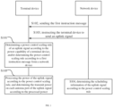
- the power control scaling rule of the uplink signal is determined according to the power capability of the terminal device, and/or the power control scaling rule is determined according to the first instruction message from the network device, to scale the power of the uplink signal according to the scaling rule, so that the terminal device with the partial antenna coherent transmission capability and non-coherent transmission capability can perform the low-rank transmission at the maximum transmit power, thereby improving the performance of the terminal device at the edge of the cell.
- the Physical Uplink Shared Channel (PUSCH) of the 3GPP NR Release 15 and Release 16 versions of the NR system supports two uplink transmission schemes: codebook-based transmission and non-codebook based transmission.
- the codebook-based uplink transmission scheme is a multi-antenna transmission technology that determines the precoding matrix of the uplink transmission based on a fixed codebook.
- the procedure of the codebook-based uplink transmission scheme is roughly as follows: a UE sends a Sounding Reference Signal (SRS) for acquiring the Channel State Information (CSI) of the codebook-based uplink transmission scheme to a base station.
- the base station performs the uplink channel detection according to the SRS sent by the UE, performs the resource scheduling for the UE, and determines the SRS resources corresponding to the uplink transmission, the number of layers of the uplink transmission and the precoding matrix, and further determines the Modulation and Coding (MCS) of the uplink transmission according to the precoding matrix and channel information.
- SRS Sounding Reference Signal
- CSI Channel State Information
- the base station notifies the UE of the PUSCH resource allocation and corresponding MCS, Transmit Precoding Matrix Indicator (TPMI), the number of transmission layers and the corresponding SRS resource indicator (SRI).
- TPMI Precoding Matrix Indicator
- SRI SRS resource indicator
- the UE modulates and encodes the data according to the MCS indicated by the base station, and uses the SRI, TPMI, and number of transmission layers indicated by the base station to determine the precoding matrix and the number of transmission layers used when sending the data, and then precodes and sends the data.
- the PUSCH demodulation pilot and the PUSCH data use the same precoding method.
- the base station estimates the uplink channel based on the demodulated pilot signal and performs the data detection.
- the characteristics of the transmission antenna and radio frequency are quite different from those of the base station, and the codebook design needs to fully consider the correlation characteristics between the antennas.
- the UE can use the two antenna ports to perform the data transmission of the same layer at the same time through precoding, to obtain the array gain.
- factors such as the mutual coupling effect of antenna elements, feeder differences, and changes in the phase and gain of the amplifier of the radio frequency path, there are inevitably differences in power and phase among actual antenna ports of the UE.
- not all UEs can calibrate each antenna port to a degree that meets the coherent transmission requirement.
- the optimal uplink transmission precoding of the UE may not be the precoding indicated by the TPMI, that is, the UE uses the precoding indicated by the base station through the TPMI for the PUSCH transmission, which cannot achieve the better performance.
- the base station can send the codebook subset restriction signaling to the UE based on the antenna coherent transmission capability of the UE to restrict the UE from using a part of precoding matrices for uplink transmission.
- the NR system defines three types of UE's antenna coherent transmission capabilities, namely: full-coherent, that is, all antennas can transmit coherently; partial-coherent, that is, the antennas in the same coherent transmission group can transmit coherently but the coherent transmission cannot be performed among coherent transmission groups, and each coherent transmission group contains two antennas; and non-coherent, that is, no antenna can transmit coherently.
- the antenna coherent transmission capability of the UE (or the coherent capability of antennas of the UE) is indicated by the codebook subset type parameter supported by the UE, i.e., pusch-TransCoherence parameter of UE capability parameter MIMO-ParametersPerBand (see 3GPP protocol TS38.306 and TS38.331).
- the pusch-TransCoherence defines the uplink codebook subset type supported by the UE when precoding the PUSCH, and its value can be nonCoherent, partialNonCoherent, or fullCoherent. When the value of pusch-TransCoherence is nonCoherent, the UE only supports a codebook subset for noncoherent transmission.
- pusch-TransCoherence taking the value of nonCoherent corresponds to the fact that all antennas of the terminal are unable to transmit coherently (correspondingly, the antenna coherent transmission capability of the UE is non-coherent).
- the UE only supports a codebook subset for non-coherent transmission and a codebook subset for partial coherent transmission.
- pusch-TransCoherence taking the value of partialNonCoherent corresponds to the fact that the antennas in the same coherent transmission group of the terminal can transmit coherently (correspondingly, the antenna coherent transmission capability of the terminal is partial coherent).
- the UE supports a codebook subset for non-coherent transmission, a codebook subset for partial coherent transmission, and a codebook subset for fully coherent transmission, that is, all codewords in the codebook.
- pusch-TransCoherence taking the value of fullCoherent corresponds to the fact that all antennas of the terminal can transmit coherently (correspondingly, the coherence capability of antennas of the terminal is full coherent).
- the process of adopting the multi-antenna power allocation mode of the PUSCH of the uplink MIMO is: the UE performs the power scaling on the transmit power calculated by the uplink power control formula according to the ratio of the number of ports that transmit signals actually to the total number of ports configured by the network device for the transmission mode corresponding to the PUSCH, and then divides the scaled power evenly among the antenna ports that transmit signals actually.
- the uplink transmission is configured with 4 antenna ports
- the precoding matrix indicated by the base station is as shown in formula (1)
- the transmit power calculated by the UE according to the PUSCH power control formula is P
- the actual transmit power of the PUSCH is P/2.
- the transmit power of each of the first antenna port and the third antenna port is P/4.
- the base station when the UE is located at the edge of a cell or the channel conditions are poor, the base station usually configures the UE with the transmission with a low number of transmission layers (or rank) and the UE transmits the data with the maximum transmit power as possible.
- the codebook design of the NR system for the codebook-based uplink transmission, there are always some antenna ports without PUSCH transmission when the UE with the partial antenna coherent transmission capability and non-coherent transmission capability performs the low-rank transmission.
- the current uplink MIMO multi-antenna power allocation mechanism cannot ensure that the UE with the partial antenna coherent transmission capability and non-coherent transmission capability can reach the maximum transmit power during the low-rank transmission under the codebook-based uplink transmission scheme, thereby reducing the performance of the UE at the edge of the cell and affecting the coverage of the cell.
- the embodiments of the present application provide an uplink power control method, a terminal device and a network device.
- the power control scaling rule of the uplink signal is determined according to the power capability of the terminal device, and/or the power control scaling rule is determined according to the first instruction message from the network device, to scale the power of the uplink signal according to the scaling rule, so that the terminal device with the partial antenna coherent transmission capability and non-coherent transmission capability can reach the maximum transmit power during the low-rank transmission, thereby improving the performance of the terminal device at the edge of the cell.
- an embodiment of the present application provides an uplink power control method, and the process of this method is described as follows. Since the uplink power control method involves the interaction process between a terminal device and a network device, the processes performed by the terminal device and the network device will be described together in the following flow description.
- the terminal device can determine the power of the uplink signal according to the power capability of the terminal device, to ensure as much as possible that the terminal device with partial antenna coherent transmission capability and non-coherent transmission capability can reach the maximum transmission power during the low-rank transmission to improve the performance of the terminal device at the edge of the cell.
- the terminal device may determine the power control scaling rule of the uplink signal in two ways as follows.
- the terminal device determines the power control scaling rule of the uplink signal according to the power capability of the terminal device.
- the terminal device determines the power control scaling rule according to the first instruction message from the network device.
- the power capability of the terminal device may include the following types.
- Type 1 default power capability.
- the power capability can be specified by the communication protocol for at least one antenna connector or the number of antenna ports of the terminal device.
- the maximum transmission power requirement can be specified by the communication protocol for a single Antenna Connector (AC) of the terminal device.
- the communication protocol requires each AC of the terminal device can reach the maximum transmit power requirement.
- the communication protocol requires that at least one AC of the terminal device can reach the maximum transmission power requirement.
- the communication protocol requires that each AC of the terminal device can reach one half of the maximum transmission power requirement.
- the communication protocol requires that each antenna connector of the terminal device can reach a quarter of the maximum transmit power requirement, and so on.
- the default power capability may also be the power capability defaulted by the network device when the terminal device does not report the power capability to the network device.
- Type 2 the power capability indicated by a power capability indication message sent by the terminal device to the network device.
- the terminal device may report the power capability to the network device, that is, the terminal device may send a power capability indication message for indicating the power capability to the network device, where the power capability indication message carries the information for indicating the power capability.
- the terminal device may report the power capability to the network device in any one of direct indication ways as follows.
- the first signaling parameter may be the parameter powercapability
- a set of candidate values included may be ⁇ "fullPower", “ParitalPower”, “limitedPower” ⁇ .
- fullPower means that the transmit power of each AC (or antenna port, or power amplifier) of the terminal device can reach the maximum power requirement.
- ParitalPower means that the transmit power of each AC (or antenna port, or power amplifier) of the terminal device can reach one half of the maximum power requirement, or the sum of transmit powers of any two ACs of the terminal device can reach the maximum transmission power requirement.
- limitedPower means that the transmit power of each AC (or antenna port, or power amplifier) of the terminal device can reach a quarter of the maximum power requirement, or the capability of a single AC (or antenna port, or power amplifier) of the terminal device does not reach the specific requirement.
- a set of candidate values included in the first signaling parameter may be ⁇ "fullPower", “limitedPower” ⁇ .
- the value “fullPower” means that the transmit power of each AC (or antenna port, or power amplifier) of the terminal device can reach the maximum power requirement.
- the value “limitedPower” means that the capability of a single AC (or antenna port, or power amplifier) of the terminal device does not reach the specific requirement.
- the first parameter signaling may also be represented by other ways, and a set of candidate values included in the first signaling parameter may also be ⁇ "fullPower", “ParitalPower” ⁇ , etc., which will not be repeated here.
- the power capability indication message reported by the terminal device to the network device includes a first signaling parameter of the terminal device, where the first signaling parameter includes multiple states, and different states indicate different power capabilities.
- the first signaling parameter occupies 2 bits and contains 4 states.
- State 0 means that the transmit power of each AC (or antenna port, or power amplifier) of the terminal device can reach the maximum power requirement.
- State 1 means that the transmit power of each AC (or antenna port, or power amplifier) of the terminal device can reach one half of the maximum power requirement.
- State 2 means that the transmit power of each AC (or antenna port, or power amplifier) of the terminal device can reach a quarter of the maximum power requirement, or the capability of a single AC (or antenna port, or power amplifier) of the terminal device does not reach the specific requirement.
- the signaling parameter is indicated by 1 bit, in this case, one state means that the transmission power of each AC (or antenna port, or power amplifier) of the terminal device can reach the maximum power requirement, and the other state means that the capability of a single AC (or antenna port, or power amplifier) of the terminal device does not reach the specific requirement.
- the terminal device reports a power capability indication message of the terminal device to the network device, the power capability indication message corresponds to a certain power capability of the terminal device. If the terminal device does not report this power capability indication message, it indicates a certain default capability of the terminal device, for example, the capability of a single AC (or antenna port, or power amplifier) of the terminal device does not reach the specific requirement.
- the power capability reported by the terminal device to the network device may also be indirectly indicated as follows.
- the power capability indication message reported by the terminal device to the network device may include at least one of: the type information of the terminal device, the power class information of the terminal device, and the coherent capability information of antennas of the terminal device.
- the examples are as follows.
- the type indicated by the type information of the supported protocol of the terminal device reported by the terminal device to the network device is R16. If the communication protocol requires that the capability of each AC, or the capability of each antenna port, or the capability of each power amplifier of the terminal device of R16 can reach the maximum power requirement corresponding to the power class of the terminal device, it is equivalent to indirectly indicating that the capability of each AC, or the capability of each antenna port, or the capability of each power amplifier of the terminal device can reach the maximum power requirement corresponding to the power class of the terminal device.
- the communication protocol requires that the capability of each AC, or the capability of each antenna port, or the capability of each power amplifier of the terminal device of R16 can reach one half of the maximum power requirement corresponding to the power class of the terminal device, it is equivalent to indirectly indicating that the capability of each AC, or the capability of each antenna port, or the capability of each power amplifier of the terminal device can reach one half of the maximum power requirement corresponding to the power class of the terminal device.
- the communication protocol does not require the capability of each AC, or the capability of each antenna port, or the capability of each power amplifier of the terminal device of R16, it is equivalent to indirectly indicating that the capability of a single AC, or the capability of a single antenna port, or the capability of single power amplifier of the terminal device does not reach the specific requirement.
- the power capability indication message reported by the terminal device to the network device includes the type information of power capability of the terminal device, it is equivalent to indirectly indicating the power capability of the terminal device.
- the power capability indication message reported by the terminal device to the network device includes the power class information of the terminal device, where the power class information can indicate the power class and indirectly indicate the power capability.
- the communication protocol specifies the maximum power requirement of each AC or antenna port or power amplifier of the terminal device with regard to the power class of the terminal device. If the maximum power requirement is the maximum output power requirement formulated by the communication protocol for the power class of the terminal device, the terminal device can obtain the relationship between the transmit power and the maximum power requirement of each AC, or antenna port, or power amplifier of the terminal device according to the maximum power requirement of the AC, or antenna port, or power amplifier of the terminal device and the maximum output power requirement formulated by the communication protocol for the power class of the terminal device.
- the communication protocol requires that the capability of each AC, or antenna port, or power amplifier of the terminal device at this power class can reach the maximum output power requirement corresponding to the power class of the terminal device, it is equivalent to indirectly indicating that the capability of each AC, or antenna port, or power amplifier of the terminal device can reach the maximum power requirement corresponding to the power class of the terminal device.
- the communication protocol requires that the capability of each AC, or antenna port, or power amplifier of the terminal device at this power class can reach one half of the maximum power requirement corresponding to the power class of the terminal device, it is equivalent to indirectly indicating that the capability of each AC, or antenna port, or power amplifier of the terminal device can reach one half of the maximum power requirement corresponding to the power class of the terminal device.
- the communication protocol does not require the capability of each AC, or antenna port, or power amplifier of the terminal device at this power class, it is equivalent to indirectly indicating that the capability of a single AC, or antenna port, or power amplifier of the terminal device does not reach the specific requirement.
- the power capability indication message reported by the terminal device to the network device includes the coherent capability information of antennas of the terminal device, where the coherent capability information indicates the power capability.
- the coherent capability information may be implemented in the form of codebook subset capability parameter. That is, the power capability indication message includes a codebook subset capability parameter to indicate the coherent capability information.
- the coherent capability information reported by the terminal device is "nonCoherent", it corresponds to indicating to the network device that "the transmit power of each AC, or antenna port, or power amplifier of the terminal device can reach the maximum power requirement". If the coherent capability information reported by the terminal device is "partialAndNonCoherent”, it corresponds to indicating to the network device that "the transmit power of eachAC, or antenna port, or power amplifier of the terminal device can reach one half of the maximum power requirement”. If the coherent capability information reported by the terminal device is "fullyAndPartialAndNonCoherent”, it corresponds to indicating to the network device that "the transmit power of each AC, or antenna port, or power amplifier of the terminal device can reach a quarter of the maximum power requirement”.
- the coherent capability reported by the terminal device is "fullyAndPartialAndNonCoherent", it corresponds to indicating to the network device that "the capability of a single AC, or antenna port, or power amplifier of the terminal device does not reach the specific requirement".
- Type 3 at least one of the power capabilities as follows.
- the power capability may include at least one of the following capabilities.
- N in the above (1)-(26) is a positive integer, for example, N is 2, 4, 8, 16, etc.
- N is the number of antenna ports corresponding to the uplink signal MIMO.
- M is, for example, a positive integer such as 1, 2, 4, 8, 16, etc.
- M is determined according to the coherent transmission capability of the terminal device.
- M is the maximum number of antenna ports through which the terminal device can perform coherent transmission.
- M may be 2.
- the maximum number of antenna ports through which the terminal device with non-coherent transmission capability can perform coherent transmission is 1, M may be 1.
- the maximum number of antenna ports through which the terminal device with fully coherent transmission capability can perform coherent transmission is 4, M may be 4.
- Q can be any positive integer.
- the default power capability in the first type of power capability may be any one or more of the default third type of power capability.
- the second type of power capability indicated by the power capability indication message sent by the terminal device to the network device may be any one or more of the third type of power capability.
- the terminal device after determining the power capability, can determine the power control scaling rule according to the power capability.
- some possible power control scaling rules include: not scaling the transmit power of the uplink signal calculated according to high-level parameters; or scaling the transmit power of the uplink signal calculated according to high-level parameters by a power control scaling factor.
- the transmit power of the uplink signal calculated according to high-level parameters is scaled by a power control scaling factor of 1; the transmit power of the uplink signal calculated according to high-level parameters is scaled by a power control scaling factor of 1/2; the transmit power of the uplink signal calculated according to high-level parameters is scaled by a power control scaling factor of 3/4; the transmit power of the uplink signal calculated according to high-level parameters is scaled by a ratio of the number of ports that send signals actually to the total number of ports configured by the network device for the transmission mode corresponding to the uplink signal; when the number of antenna ports configured by the network device for the uplink transmission mode of the uplink signal is greater than 1 and the indicated precoding matrix corresponds to single-layer NC (non-coherent) codewords, the power control scaling
- the terminal device may determine the power control scaling rule of the uplink signal according to the power capability and the power class of the terminal device, where the power class of the terminal device is indicated by the network device, or reported by the terminal device, which may specifically include the following cases.
- the power capability reported by the terminal device is that the terminal device contains two PAs, and the power capability of the two PAs is ⁇ 23dBm + 23dBm ⁇ ; and the power class of the terminal device is Class 3, i.e., the maximum output power requirement is 23dBm, then the power capability of the terminal device is that the power of each PA of the terminal device can reach the maximum output power of the power class corresponding to the terminal.
- the power control scaling rule for when the power capability of the terminal device is that the power of each PA of the terminal device can reach the maximum output power of the power class corresponding to the terminal can be used.
- the following power control scaling rule is adopted: not scaling the transmit power of the uplink signal calculated according to high-level parameters, or scaling the transmit power of the uplink signal calculated according to high-level parameters by a power control scaling factor of 1.
- the power capability reported by the terminal device is that the terminal device contains two PAs, and the power capability of the two PAs is ⁇ 20dBm + 20dBm ⁇ ; and the power class of the terminal device is Class 3, i.e., the maximum output power requirement is 23dBm.
- the power capability of the terminal device is that the power of each PA of the terminal device can reach 1/2 of the maximum output power of the power class corresponding to the terminal device.
- the power control scaling rule for when the power capability of the terminal device is that the power of each PA of the terminal device can reach 1/2 of the maximum output power of the power class corresponding to the terminal device can be used.
- the following power control scaling rule is adopted: when the number of antenna ports configured by the network device for the uplink transmission mode of the uplink signal is 2 and the indicated precoding matrix corresponds to single-layer non-coherent transmission codewords, the transmit power of the uplink signal calculated according to the high-level parameters is scaled by a power control scaling factor of 1/2; when the precoding matrix corresponds to other codewords, the transmit power of the uplink signal calculated according to the high-level parameters is not scaled.
- the transmit power of the uplink signal calculated according to the high-level parameters is scaled by a power control scaling factor of 1/2; when the precoding matrix corresponds to other codewords, the transmit power of the uplink signal calculated according to the high-level parameters is not scaled.
- the terminal device may determine the power control scaling rule according to the power capability and at least one of the following parameters.
- the following parameters may include: the number of antenna ports configured by the network device for uplink signal transmission, the precoding matrix corresponding to the uplink signal, the codebook subset restriction type corresponding to the uplink signal, the number of transmission layers corresponding to the uplink signal, and the maximum power of the uplink transmission.
- the terminal device may determine the power control scaling rule according to the power capability of the terminal device and the number of coherent antenna groups associated with non-zero elements in the precoding matrix corresponding to the uplink signal.
- the terminal device may determine the power control scaling rule according to the power capability and the codeword coherent transmission type corresponding to the precoding matrix corresponding to the uplink signal.
- the terminal device may determine the power control scaling rule according to the power capability, the number of coherent antenna groups associated with non-zero elements in the precoding matrix corresponding to the uplink signal, and the number of antenna ports configured by the network device for the uplink signal transmission.
- the terminal device may determine the power control scaling rule according to the power capability, the codeword coherent transmission type corresponding to the precoding matrix corresponding to the uplink signal, and the number of antenna ports configured for the uplink signal transmission.
- the terminal device may determine the power control scaling rule according to the power capability, the codeword coherent transmission type corresponding to the precoding matrix corresponding to the uplink signal, and the number of transmission layers corresponding to the uplink signal.
- the terminal device may determine the power control scaling rule according to the power capability, the coherent transmission type corresponding to the precoding matrix corresponding to the uplink signal, the number of transmission layers corresponding to the uplink signal, and the number of antenna ports configured by the network device for the uplink signal transmission.
- the terminal device may determine the power control scaling rule according to the power capability, the codebook subset restriction type corresponding to the uplink signal, and the number of antenna ports configured by the network device for the uplink signal transmission.
- the terminal device may determine the power control scaling rule according to the power capability, the codebook subset restriction type corresponding to the uplink signal, the number of transmission layers corresponding to the uplink signal, and the number of antenna ports configured by the network device for the uplink signal transmission.
- the terminal device may determine the power control scaling rule according to the power capability, the codebook subset restriction type corresponding to the uplink signal, and the coherent transmission type corresponding to the precoding matrix corresponding to the uplink signal.
- the terminal device may determine the power control scaling rule according to the power capability, the codebook subset restriction type corresponding to the uplink signal, the coherent transmission type corresponding to the precoding matrix corresponding to the uplink signal, and the number of antenna ports configured by the network device for the uplink signal transmission.
- the terminal device may determine the power control scaling rule according to the power capability, the codebook subset restriction type corresponding to the uplink signal, the coherent transmission type corresponding to the precoding matrix corresponding to the uplink signal, the number of transmission layers corresponding to the uplink signal, and the number of antenna ports configured by the network device for the uplink signal transmission.
- the terminal device may determine the power control scaling rule according to the power capability and the maximum power of uplink transmission, which may be as follows.
- the power capability reported by the terminal device is that the terminal contains two PAs, and the power capability of the two PAs is ⁇ 23dBm + 23dBm ⁇ ; and the maximum power of uplink transmission is 23dBm.
- the power capability of the terminal device is that the power of each PA of the terminal and can reach the maximum power of uplink transmission.
- the power control scaling rule for when the power capability of the terminal device is that the power of each PA of the terminal device can reach the maximum power of uplink transmission can be used.
- the following power control scaling rule is adopted: not scaling the transmit power of the uplink signal calculated according to high-level parameters, or scaling the transmit power of the uplink signal calculated according to high-level parameters by a power control scaling factor of 1.
- the power capability reported by the terminal device is that the terminal contains two PAs, and the power capability of the two PAs is ⁇ 20dBm + 20dBm ⁇ ; and the maximum power of uplink transmission is 23dBm. Then the power capability of the terminal device is that the power of each PA of the terminal can reach 1/2 of the maximum power of uplink transmission.
- the power control scaling rule for when the power capability of the terminal device is that the power of each PA of the terminal device can reach 1/2 of the maximum power of uplink transmission can be used.
- the following power control scaling rule is adopted: when the number of antenna ports configured by the network device for the uplink transmission mode of the uplink signal is 2 and the indicated precoding matrix corresponds to single-layer non-coherent transmission codewords, the transmit power of the uplink signal calculated according to the high-level parameters is scaled by a power control scaling factor of 1/2; when the precoding matrix corresponds to other codewords, the transmit power of the uplink signal calculated according to the high-level parameters is not scaled.
- the transmit power of the uplink signal calculated according to the high-level parameters is scaled by a power control scaling factor of 1/2; when the precoding matrix corresponds to other codewords, the transmit power of the uplink signal calculated according to the high-level parameters is not scaled.
- the terminal device determines the power control scaling rule according to the first instruction message from the network device.
- a network device may determine the power control scaling rule of the uplink signal according to the power capability of a terminal device, and then may send a first instruction message to the terminal device to inform the terminal device of the power control scaling rule.
- the first instruction message indicates the power control scaling rule, and/or, the first instruction message is a message indicating the power capability.
- the first instruction message instructs the terminal device to determine the power control scaling rule according to at least one of the following parameters.
- the parameters may include: the number of antenna ports configured by the network device for uplink signal transmission, the precoding matrix corresponding to the uplink signal, the codebook subset restriction type corresponding to the uplink signal, the number of transmission layers corresponding to the uplink signal, and the maximum power of the uplink transmission.
- the network side device determines the power control scaling rule according to at least one of the following parameters.
- the parameters may include: the number of antenna ports configured by the network device for uplink signal transmission, the precoding matrix corresponding to the uplink signal, the codebook subset restriction type corresponding to the uplink signal, the number of transmission layers corresponding to the uplink signal, and the maximum power of the uplink transmission.
- the terminal device determines the power control scaling rule according to the indication of the first instruction message and at least one of the following parameters.
- the parameters may include: the number of antenna ports configured by the network device for uplink signal transmission, the precoding matrix corresponding to the uplink signal, the codebook subset restriction type corresponding to the uplink signal, the number of transmission layers corresponding to the uplink signal, and the maximum power of the uplink transmission.
- the terminal device may determine the power control scaling rule according to the first instruction message and the number of coherent antenna groups associated with non-zero elements in the precoding matrix corresponding to the uplink signal.
- the terminal device may determine the power control scaling rule according to the first instruction message and the codeword coherent transmission type corresponding to the precoding matrix corresponding to the uplink signal.
- the terminal device may determine the power control scaling rule according to the first instruction message, the number of coherent antenna groups associated with non-zero elements in the precoding matrix corresponding to the uplink signal, and the number of antenna ports configured by the network device for the uplink signal transmission.
- the terminal device may determine the power control scaling rule according to the first instruction message, the codeword coherent transmission type corresponding to the precoding matrix corresponding to the uplink signal, and the number of antenna ports configured for the uplink signal transmission.
- the terminal device may determine the power control scaling rule according to the first instruction message, the codeword coherent transmission type corresponding to the precoding matrix corresponding to the uplink signal, and the number of transmission layers corresponding to the uplink signal.
- the terminal device may determine the power control scaling rule according to the first instruction message, the coherent transmission type corresponding to the precoding matrix corresponding to the uplink signal, the number of transmission layers corresponding to the uplink signal, and the number of antenna ports configured by the network device for the uplink signal transmission.
- the terminal device may determine the power control scaling rule according to the first instruction message, the codebook subset restriction type corresponding to the uplink signal, and the number of antenna ports configured by the network device for the uplink signal transmission.
- the terminal device may determine the power control scaling rule according to the first instruction message, the codebook subset restriction type corresponding to the uplink signal, the number of transmission layers corresponding to the uplink signal, and the number of antenna ports configured by the network device for the uplink signal transmission.
- the terminal device may determine the power control scaling rule according to the first instruction message, the codebook subset restriction type corresponding to the uplink signal, and the coherent transmission type corresponding to the precoding matrix corresponding to the uplink signal.
- the terminal device may determine the power control scaling rule according to the first instruction message, the codebook subset restriction type corresponding to the uplink signal, the coherent transmission type corresponding to the precoding matrix corresponding to the uplink signal, and the number of antenna ports configured by the network device for the uplink signal transmission.
- the terminal device may determine the power control scaling rule according to the first instruction message, the codebook subset restriction type corresponding to the uplink signal, the coherent transmission type corresponding to the precoding matrix corresponding to the uplink signal, the number of transmission layers corresponding to the uplink signal, and the number of antenna ports configured by the network device for the uplink signal transmission.
- the network device may determine the power control scaling rule according to the number of coherent antenna groups associated with non-zero elements in the precoding matrix corresponding to the uplink signal.
- the network device may determine the power control scaling rule according to the codeword coherent transmission type corresponding to the precoding matrix corresponding to the uplink signal.
- the network device may determine the power control scaling rule according to the number of coherent antenna groups associated with non-zero elements in the precoding matrix corresponding to the uplink signal and the number of antenna ports configured by the network device for the uplink signal transmission.
- the network device may determine the power control scaling rule according to the codeword coherent transmission type corresponding to the precoding matrix corresponding to the uplink signal and the number of antenna ports configured for the uplink signal transmission.
- the network device may determine the power control scaling rule according to the codeword coherent transmission type corresponding to the precoding matrix corresponding to the uplink signal and the number of transmission layers corresponding to the uplink signal.
- the network device may determine the power control scaling rule according to the coherent transmission type corresponding to the precoding matrix corresponding to the uplink signal, the number of transmission layers corresponding to the uplink signal, and the number of antenna ports configured by the network device for the uplink signal transmission.
- the network device may determine the power control scaling rule according to the codebook subset restriction type corresponding to the uplink signal and the number of antenna ports configured by the network device for uplink signal transmission.
- the network device may determine the power control scaling rule according to the codebook subset restriction type corresponding to the uplink signal, the number of transmission layers corresponding to the uplink signal, and the number of antenna ports configured by the network device for the uplink signal transmission.
- the network device may determine the power control scaling rule according to the codebook subset restriction type corresponding to the uplink signal and the coherent transmission type corresponding to the precoding matrix corresponding to the uplink signal.
- the network device may determine the power control scaling rule according to the codebook subset restriction type corresponding to the uplink signal, the coherent transmission type corresponding to the precoding matrix corresponding to the uplink signal, and the number of antenna ports configured by the network device for the uplink signal transmission.
- the network device may determine the power control scaling rule according to the codebook subset restriction type corresponding to the uplink signal, the coherent transmission type corresponding to the precoding matrix corresponding to the uplink signal, the number of transmission layers corresponding to the uplink signal, and the number of antenna ports configured by the network device for the uplink signal transmission.
- S103 the network device instructs the terminal device to send an uplink signal.
- S102 is not essential and, where it exists, there is no precedence order between S102 and S103.
- the network device may send a codebook subset restriction parameter to the terminal device, where the codebook subset restriction parameter carries the first instruction message.
- the first instruction message may carry a first parameter, and the first parameter indicates the type of the power control scaling rule, and different types correspond to different power control scaling rules.
- the first instruction message may carry a second parameter, and the second parameter indicates whether the terminal device transmits an uplink signal at full power.
- the network device determines the scheduling information of the uplink signal according to the power control scaling rule.
- the scheduling information of the uplink signal includes at least one of: precoding, layer number indication information (for example, indicated by "Precoding information and number of layers” in DCI format 0_1 of the 3GPPNR system), SRS indication information (for example, indicated by "SRS resource indicator” in DCI format 0_1 of the 3GPP NR system), and Modulation and Coding level (MCS) information.
- MCS Modulation and Coding level
- different first instruction messages correspond to different power control scaling rules.
- the terminal device can determine the power control scaling rule according to the power capability.
- the terminal device may determine the power control scaling rule according to the first instruction message. Specifically, after determining the power capability, the terminal device may judge whether the power capability and at least one of the above-mentioned parameters satisfy the first preset condition when determining the power control scaling rule according to the power capability, and may determine the power control scaling rule as a first power control scaling rule if the first preset condition is satisfied. Alternatively, the terminal device may judge whether the power capability satisfies the second preset condition, and may determine the power control scaling rule as a second power control scaling rule if the second preset condition is satisfied.
- the terminal device may judge whether the first instruction message satisfies the third preset condition, and determine the power control scaling rule as a certain power control scaling rule if the first instruction message satisfies the third preset condition.
- the first preset condition may be: the transmit power of each antenna port or AC or PA of the terminal device can reach the maximum output power requirement corresponding to the power class of the terminal device. Or, the terminal device can transmit the uplink signal at full power. Or, the transmit power of each antenna port or AC or PA of the terminal device can reach one half of the maximum output power requirement corresponding to the power class of the terminal device, the number of antenna ports configured by the network device for the uplink transmission mode of the uplink signal is greater than 1, and the indicated precoding matrix corresponds to single-layer NC codewords.
- the terminal device can transmit the uplink signal at full power, the number of antenna ports configured by the network device for the uplink transmission mode of the uplink signal is greater than 1, and the indicated precoding matrix corresponds to single-layer NC codewords.
- the transmit power of each antenna port or AC or PA of the terminal device can reach a quarter of the maximum output power requirement corresponding to the power class of the terminal device, the number of antenna ports configured by the network device for the uplink transmission mode of the uplink signal is greater than 1, and the indicated precoding matrix corresponds to three-layer NC codewords, etc.
- the terminal device can transmit the uplink signal at full power, the number of antenna ports configured by the network device for the uplink transmission mode of the uplink signal is greater than 1, and the indicated precoding matrix corresponds to three-layer NC codewords, etc.
- the second preset condition may be: the transmit power of each antenna port or AC or PA of the terminal device can reach the maximum output power requirement corresponding to the power class of the terminal device. Or, the terminal device can transmit the uplink signal at full power. Or, the terminal device cannot transmit the uplink signal at full power. Or, the transmit power of each antenna port or AC or PA of the terminal device can reach a quarter of the maximum output power requirement corresponding to the power class of the terminal device. Or, a single antenna port or AC or PA of the terminal device does not reach the specific requirement.
- the terminal device does not report the capability of each antenna port or AC or PA.
- the communication protocol does not specify the performance requirement for the capability of each antenna port or AC or PA of the terminal device.
- the transmit power of each antenna port or AC or PA of the terminal device can reach the maximum power of uplink transmission.
- the transmit power of each antenna port or AC or PA of the terminal device can reach a quarter of the maximum power of uplink transmission.
- a single antenna port of the terminal device does not reach the specific requirement.
- the terminal device does not report the capability of each antenna port.
- the communication protocol does not specify the performance requirement for the capability of each antenna port or AC or PA of the terminal device. The above are only examples of the first preset condition and second preset condition.
- the terminal device processes the transmit power of the uplink signal when the specific conditions are met as an example.
- the terminal device scales the power of the uplink signal according to the power control scaling rule determined according to whether the power capability and/or the parameters satisfy the first preset condition or the second preset condition.
- the first preset condition is that the transmit power of each antenna port or AC or PA of the terminal device can reach one half of the maximum output power requirement corresponding to a power class of the terminal device, the number of antenna ports configured by the network device for an uplink transmission mode of the uplink signal is greater than 1, and the indicated precoding matrix corresponds to single-layer NC codewords, and the power control scaling rule is scaling the transmit power of the uplink signal calculated according to high-level parameters by a power control scaling factor of 1/2.
- the first preset condition is that the transmit power of each antenna port or AC or PA of the terminal device can reach a quarter of the maximum output power requirement corresponding to a power class of the terminal device, the number of antenna ports configured by the network device for an uplink transmission mode of the uplink signal is greater than 1, and the indicated precoding matrix corresponds to three-layer NC codewords, and the power control scaling rule is scaling the transmit power of the uplink signal calculated according to high-level parameters by a power control scaling factor of 3/4.
- the first preset condition is that the power capability of the terminal device is that the transmit power of each antenna port or AC or PA of the terminal device can reach one half of the maximum power of uplink transmission, the number of antenna ports configured by the network device for an uplink transmission mode of the uplink signal is greater than 1, and the indicated precoding matrix corresponds to single-layer NC codewords, and the power control scaling rule is scaling the transmit power of the uplink signal calculated according to high-level parameters by a power control scaling factor of 1/2.
- the first preset condition is that the transmit power of each antenna port or AC or PA of the terminal device can reach one half of the maximum power of uplink transmission, the number of antenna ports configured by the network device for an uplink transmission mode of the uplink signal is greater than 1, and the indicated precoding matrix corresponds to three-layer NC codewords, and the power control scaling rule is scaling the transmit power of the uplink signal calculated according to high-level parameters by a power control scaling factor of 3/4.
- the second preset condition is that the transmit power of each antenna port or AC or PA of the terminal device can reach a maximum output power requirement corresponding to a power class of the terminal device, and the power control scaling rule is not scaling the transmit power of the uplink signal calculated according to high-level parameters or the power control scaling rule is scaling the transmit power of the uplink signal calculated according to high-level parameters by a power control scaling factor of 1.
- the second preset condition is that the transmit power of each antenna port or AC or PA of the terminal device can reach a quarter of the maximum output power requirement corresponding to a power class of the terminal device, or a single antenna port or AC or PA of the terminal device does not reach a specific requirement, or the terminal device does not report the capability of each antenna port or AC or PA, or a communication protocol does not formulate a performance requirement for each antenna port or AC or PA of the terminal device, and the power control scaling rule is scaling the transmit power of the uplink signal calculated according to high-level parameters by a ratio of the number of ports that send signals actually to the total number of ports configured by the network device for a transmission mode corresponding to the uplink signal.
- the second preset condition is that the transmit power of each antenna port or AC or PA of the terminal device can reach the maximum power of uplink transmission, and the power control scaling rule is not scaling the transmit power of the uplink signal calculated according to high-level parameters or the power control scaling rule is scaling the transmit power of the uplink signal calculated according to high-level parameters by a power control scaling factor of 1.
- the second preset condition is that the transmit power of each antenna port or AC or PA of the terminal device can reach a quarter of the maximum power of uplink transmission, or a single antenna port of the terminal device does not reach a specific requirement, or the terminal device does not report the capability of each antenna port, or a communication protocol does not formulate a performance requirement for each antenna port or AC or PA of the terminal device, and the power control scaling rule is scaling the transmit power of the uplink signal calculated according to high-level parameters by a ratio of the number of ports that send signals actually to the total number of ports configured by the network device for a transmission mode corresponding to the uplink signal.
- the third preset condition is that the first instruction message instructs the terminal device to transmit the uplink signal at full power, and the power control scaling rule is not scaling the transmit power of the uplink signal calculated according to high-level parameters or the power control scaling rule is scaling the transmit power of the uplink signal calculated according to high-level parameters by a power control scaling factor of 1.
- the terminal device may scale the transmit power of the uplink signal calculated according to high-level parameters by the power control scaling factor in the following power control scaling rule.
- R is the number of transmission layers of the uplink signal
- ⁇ 0 is the number of ports of non-zero transmission corresponding to the precoding matrix of the uplink signal
- ⁇ is the number of antenna ports configured by the network device for the uplink signal transmission.
- the terminal device adopts the power control scaling rule in (1) described above.
- ⁇ is the number of antenna ports configured by the network device for the uplink signal transmission
- G is a coefficient related to the power capability of the terminal device.
- the power capability of the terminal device is the capability that the transmit power of each antenna port (or eachAC, or each PA) of the terminal device can reach the maximum power requirement or the terminal device can perform uplink transmission at full power
- G 1
- K is a coefficient related to the number of antenna ports of the uplink signal and the codebook subset restriction type corresponding to the uplink signal. For example, K is a coefficient related to the power capability of the terminal device.
- K is a coefficient related to the number of antenna ports of the uplink signal and the codebook subset restriction type corresponding to the uplink signal.
- the value of K can be as shown in Table 1.
- the power control scaling factor of the uplink signal indicated by each precoding matrix is as shown in Table 2 below:
- Table 2 ULCodebookSubset Rank Non-coherent TPMI Partial coherent TPMI Fullycoherent TPMI nonCoherent 1 1 - - 2 1 - - 3 1 - - 4 1 - - partialCoherent 1 1/2 1 - 2 1/2 1 - 3 3/4 1 - 4 1 1 - fullAndPartialAndNonCoherent 1 1/4 1/2 1 2 1/2 1 1 3 3/4 1 1 4 1 1 1 1 1 1 1
- Non-coherent TPMI is a codeword for non-coherent transmission
- Partial coherent TPMI is a codeword for partial coherent transmission
- Fully coherent TPMI is a codeword for fully coherent transmission.
- the terminal device adopts the power control scaling rule in (3) described above.
- the value of K is related to the power capability of the terminal device. For example, when the power capability of the terminal device is the capability that the transmit power of each antenna port (or each AC, or each PA) of the terminal device can reach the maximum power requirement, the value of K in Table 1 above is used.
- the value of K is as shown in Table 3 when the uplink signal is transmitted with 2 antenna ports or 4 antenna ports.
- Table 3 ULCodebookSubset ⁇ K fullAndPartialAndNonCoherent 2 1 fullAndPartialAndNonCoherent 4 1 partialCoherent 4 2 nonCoherent 2 2 noncoherent 4 2
- the power control scaling factor of the uplink signal under each precoding matrix indicator in the case of 4 antenna ports is as shown in Table 4.
- Table 4 ULCodebookSubset Rank Non-coherent TPMI Partial coherent TPMI Fullycoherent TPMI nonCoherent 1 1/2 - - 2 1/2 - - 3 3/4 - - 4 1 - - partialCoherent 1 1/2 1 - 2 1/2 1 - 3 3/4 1 - 4 1 1 1 - fullAndPartialAndNonCoh erent 1 1/4 1/2 1 2 1/2 1 1 3 3/4 1 1 4 1 1 1 1 1 1 1
- Non-coherent TPMI is a codeword for non-coherent transmission
- Partial coherent TPMI is a codeword for partial coherent transmission
- Fully coherent TPMI is a codeword for fully coherent transmission.
- the value of K is fixed to 1.
- the value of G 0 may be as shown in Table 5 below.
- ULCodebookSubset in Table 5 is an indication parameter of the codebook subset restriction type corresponding to the uplink signal of the terminal device indicated by the network device to the terminal device (for example, indicated by the RRC signaling parameter ULCodebookSubset in the NR system).
- Table 5 ULCodebookSubset ⁇ G 0 fullAndPartialAndNonCoherent 2 1 fullAndPartialAndNonCoherent 4 1 partialCoherent 4 2 nonCoherent 2 2 nonCoherent 4 4
- the power control scaling factor of the uplink signal indicated by each precoding matrix in the case of 4 antenna ports is as shown in Table 6 below.
- Table 6 ULCodebookSubset Rank Non-coherent TPMI Partial coherent TPMI Fully coherent TPMI nonCoherent 1 1 - - 2 1 - - 3 1 - - 4 1 - - partialCoherent 1 1/2 1 - 2 1/2 1 - 3 3/4 1 - 4 1 1 1 - fullAndPartialAndNo nCoherent 1 1/4 1/2 1 2 1/2 1 1 3 3/4 1 1 4 1 1 1 1 1 1 1
- Non-coherent TPMI is a codeword for non-coherent transmission
- Partial coherent TPMI is a codeword for partial coherent transmission
- Fully coherent TPMI is a codeword for fully coherent transmission.
- the terminal device adopts the power control scaling rule in (4) described above.
- one antenna port of the terminal device may correspond to one AC or correspond to multiple ACs, which is not limited in the embodiments of the present application.
- the power capability of the terminal device is the capability that the maximum transmit power of each antenna port of the terminal device can reach the maximum power requirement
- the power capability of the terminal device is the capability that the total output maximum transmit power of the multiple ACs corresponding to each antenna port of the terminal device can reach the maximum power requirement.
- one antenna port of the terminal device corresponds to one AC
- the power capability of the terminal device is the capability that the maximum transmission power of each antenna port of the terminal device can reach the maximum power requirement
- the power capability of the terminal device is the capability that the maximum transmission power of each AC of the terminal device can reach the maximum power requirement
- the above power control scaling rule of the uplink signal may also be independent of the power capability of the antenna port of the terminal device, but rather related to the power capability of the AC.
- the above maximum power requirement may be the maximum output power requirement corresponding to the power class of the terminal device. In one embodiment, the above maximum power requirement may also be the maximum output power requirement of the sum of output powers of all ACs corresponding to the power class of the terminal device.
- TS38.101 defines the maximum output power requirement corresponding to the power class of the terminal device.
- the maximum output power requirement of the terminal device at each power class under each frequency band is defined in sections 6.2.1, 6.2D.1, etc., where it is 23dBm at power class 3.
- the first instruction message sent by the network device may be used to indicate the following power control scaling rules, which specifically include the following modes.
- K is a coefficient related to the number of antenna ports of the uplink signal and the codebook subset restriction type corresponding to the uplink signal.
- the value of K can be as shown in Table 1.
- the power control scaling factor of the uplink signal indicated by each precoding matrix is as shown in Table 2, where Non-coherent TPMI is a codeword for non-coherent transmission, Partial coherent TPMI is a codeword for partial coherent transmission, and Fully coherent TPMI is a codeword for fully coherent transmission.
- the terminal device adopts the power control scaling rule of (8) described above.
- the value of K is related to the power capability of the terminal device. For example, when the power capability of the terminal device is the capability that the transmit power of each antenna port (or each AC, or each PA) of the terminal device can reach the maximum power requirement, the value of K in Table 1 above is used.
- the value of K is as shown in Table 3 when the uplink signal is transmitted with 2 antenna ports or 4 antenna ports.
- the power control scaling factor of the uplink signal indicated by each precoding matrix in the case of 4 antenna ports is as shown in Table 4.
- the value of K is fixed to 1.
- G 0 is the number of coherent antenna groups corresponding to the precoding matrix of the uplink signal
- G is the maximum number of coherent antenna groups corresponding to all codewords in a codebook corresponding to the codebook subset restriction type of the uplink signal indicated by the network device to the terminal device
- ⁇ 0 is the number of ports of non-zero transmission corresponding to the precoding matrix of the uplink signal
- ⁇ is the number of antenna ports configured by the network device for the uplink signal transmission.
- the value of G 0 may be as shown in Table 5 above.
- ULCodebookSubset in Table 5 is an indication parameter of the codebook subset restriction type corresponding to the uplink signal indicated by the network device to the terminal device (e.g., indicated by the RRC signaling parameter ULCodebookSubset in the NR system).
- the power control scaling factor of the uplink signal indicated by each precoding matrix in the case of 4 antenna ports is as shown in Table 6.
- the terminal device adopts the power control scaling rule of (9) described above.
- the first instruction message is carried by the codebook subset restriction parameter (the high-level parameter "codebooksubset" in the 3GPP NR system) of the uplink signal sent by the network device for the terminal device.
- a possible power control scaling rule is: if the "codebooksubset" is "fullyAndPartialAndNonCoherent", the power control scaling rule corresponds to the above mode (3); if the "codebooksubset” is “partialAndNonCoherent", the power control scaling rule corresponds to the above mode (2); if "codebooksubset” is "nonCoherent”, the power control scaling rule corresponds to the above mode (1).
- the advantage of the embodiments of the present application is: for the terminal device with the strong capability of antenna port or AC, when the terminal device performs the codebook-based uplink transmission, if the network device indicates NC codewords or PC (Partial Coherent) codewords, terminal device can perform uplink transmission at greater transmission power, which can improve the uplink transmission performance of the terminal device.
- the embodiment of the present application can be used as a scaling rule for the transmit power of the uplink signal calculated according to the high-level parameters due to the MIMO transmission.
- the transmit power of the uplink signal calculated according to the high-layer signaling may correspond to P PUSCH, b , f , c ( i , j, q d , l ) calculated in section 7.1.1 of TS38.213.
- the terminal device may determine the transmit power on each antenna port of the uplink signal according to the processed power. In this case, there is one or more antenna ports. For example, the terminal device evenly divides the obtained scaled power directly to each antenna port of non-zero transmission. For another example, if the uplink signal is transmitted simultaneously with signals of other carriers, the terminal device also needs to allocate the power by certain priorities according to the power allocation rule when the signals are transmitted simultaneously, then obtain the actual transmit power of the uplink signal and then evenly divides it to each antenna port of non-zero transmission.
- the uplink signal in the embodiments of the present application may be a PUSCH or other uplink signal, e.g., Physical Uplink Control Channel (PUCCH), SRS (Sounding Reference Signal), and so on.
- PUCCH Physical Uplink Control Channel
- SRS Sounding Reference Signal
- the maximum power of uplink transmission may be at least in following way: in the 3GPP NR system, P-Max is the maximum transmit power of the uplink transmission configured by the network device for the terminal device, or the maximum transmit power of the uplink transmission specified by the protocol (see TS38.331, TS38.101 of 3GPP protocol).
- the maximum power of uplink transmission in the embodiment of the present application may correspond to the P-max.
- the maximum power of uplink transmission in the embodiment of the present application corresponds to the maximum power corresponding to the uplink signal configured by the network device for the terminal.
- the maximum power of uplink transmission is the maximum transmit power configured by the network device for the PUSCH; when the uplink signal is a PUCCH, the maximum power of uplink transmission is the maximum transmit power configured by the network device for the PUCCH.
- the maximum power of uplink transmission may be configured through other parameters in other communication systems.
- the power class of the terminal device may be at least in following way: the power class of the terminal device defined in the 3GPP protocol specification, for example, the protocols TS36.101, TS38.101-1, TS38.01-2, and TS38.101-3 define some power classes of terminal devices with some performance requirements formulated.
- the 3GPP NR system defaults the power class of the terminal device to the power class 3. If the terminal device supports other power class, it can report its power class to the network device through the indication information. In the NR system, the terminal device reports its power class to the network device through the parameters ue-CA-PowerClass-N, ue-PowerClass, etc.
- the "maximum output power corresponding to the power class of the terminal device" in the embodiment of the present application may correspond to the requirement for the maximum output power corresponding to the power class of the terminal device in the standard specification.
- the maximum output power at each power class is stipulated in section 6.2 of TS38.101-1.
- it is 23dBm at the power class 3
- Class 3 also corresponds to 23dBm in the UL MIMO.
- there may be other definitions for the power class in other systems.
- the definition of the power class in the LTE system is different from the definition of the power class in the NR system.
- the coherence capability of antennas of the terminal device or the codebook subset type supported by the terminal device may be at least in following way: the coherence capability of antennas of the terminal device can be reported by the terminal device to the network device through a parameter.
- This parameter may give a direct indication of the antennas of the terminal device that can transmit coherently and the grouping of the antennas for coherent transmission, or may give an indirect indication.
- the terminal device can be indicated by the parameter "pusch-TransCoherence" in the capability parameter "MIMO-ParametersPerBand" of the terminal device (see 3GPP protocol TS38.306 and TS38.331).
- the "pusch-TransCoherence” defines the uplink codebook subset type supported by the terminal device when precoding the PUSCH, and its value can be nonCoherent, partialNonCoherent, or fullCoherent.
- the terminal device When the value of "pusch-TransCoherence" is nonCoherent, the terminal device only supports a codebook subset for non-coherent transmission. Since the codewords in the codebook subset for non-coherent transmission are all codewords of non-coherent transmission type, it can be considered that "pusch-TransCoherence” takes the value nonCoherent, which corresponds to all antennas of the terminal device not being able to transmit coherently (correspondingly, the coherent capability of antennas is: all the antennas cannot transmit coherently).
- the terminal device When the value of "pusch-TransCoherence" is partialNonCoherent, the terminal device only supports a codebook subset for noncoherent transmission and a codebook subset for partial coherent transmission. Since the codewords in the codebook subset for partial coherent transmission are all codewords of partial coherent transmission type, it can be considered that "pusch-TransCoherence” takes the value partialNonCoherent, which corresponds to the antennas in the same coherent transmission group of the terminal device being able to transmit coherently (correspondingly, the coherent capability of antennas of the terminal device is: partial antennas can transmit coherently).
- the terminal device When the value of "pusch-TransCoherence" is fullCoherent, the terminal device supports a codebook subset for non-coherent transmission, a codebook subset for partial coherent transmission, and a codebook subset for fully coherent transmission, that is, all codewords in the codebook.
- "pusch-TransCoherence” takes the value fullCoherent, which corresponds to all antennas of the terminal device being able to transmit coherently (correspondingly, the coherent capability of antennas of the terminal device is: all the antennas can transmit coherently).
- the power control scaling rule of the uplink signal is determined according to the power capability of the terminal device, and/or the power control scaling rule is determined according to the first instruction message from the network device, to scale the power of the uplink signal according to the scaling rule, so that the UE with the partial antenna coherent transmission capability and non-coherent transmission capability can reach the maximum transmit power during the low-rank transmission, thereby improving the performance of the UE at the edge of the cell.
- the codewords in the uplink codebook can be divided into at least three coherent types (or called coherent transmission types), which are: fully coherent, partial coherent and non-coherent codewords (or called fully coherent transmission codewords, partial coherent transmission codewords and noncoherent transmission codewords).
- any column in the partial coherent transmission codewords has only non-zero elements corresponding to the same coherent transmission antenna group (in the 3GPP NR system, the first and third antennas form a coherent transmission antenna group, and the second and fourth antennas form another coherent transmission antenna group); any column in the non-coherent transmission codewords has only non-zero elements corresponding to one antenna; all the elements in at least one column in the fully coherent transmission codewords are non-zero.
- the following tables list the uplink codebooks in the 3GPP NR system and give the specific codeword types.
- the codewords with TPMI index of 0 to 1 are codewords for non-coherent transmission; and other codewords are codewords for fully coherent transmission.
- Table 6.3.1.5-1 Precoding matrix W for single-layer transmission using two antenna ports. (3GPP protocol TS38.211) TPMI index W (ordered from left to right in increasing order of TPMI index) 0-5 1 2 1 0 1 2 0 1 1 2 1 1 1 1 2 1 ⁇ 1 1 2 1 j 1 2 1 ⁇ j - - -
- the codewords with TPMI index of 0 to 3 are codewords for non-coherent transmission; the codewords with TPMI index of 4 to 11 are codewords for partial coherent transmission; and other codewords are codewords for fully coherent transmission.
- Table 6.3.1.5-2 Precoding matrix W for single-layer transmission using four antenna ports with transform precoding enabled.
- TPMI index W (ordered from left to right in increasing order of TPMI index) 0-7 1 2 1 0 0 0 1 2 0 1 0 0 1 2 0 0 1 0 1 2 0 0 0 1 1 2 1 0 1 0 1 2 1 0 ⁇ 1 0 1 2 1 0 j 0 1 2 1 0 ⁇ j 0 8-15 1 2 0 1 0 1 1 2 0 1 0 ⁇ 1 1 2 0 1 0 j 1 2 0 1 0 ⁇ j 1 2 1 1 1 1 ⁇ 1 1 2 1 1 1 ⁇ j ⁇ j 16-23 1 2 1 j 1 j 1 2 1 j j 1 1 2 1 j ⁇ 1 ⁇ 1 j 1 2 1 j ⁇ j ⁇ 1 2 1 ⁇ 1 1 1 1 2 1 ⁇ 1 j ⁇ j 1 2 1 ⁇ 1 ⁇ 1 j ⁇ 1 2 1 ⁇ 1 ⁇ 1 j ⁇ 1 2 1
- the codewords with TPMI index of 0 to 3 are codewords for non-coherent transmission; the codewords with TPMI index of 4 to 11 are codewords for partial coherent transmission; and other codewords are codewords for fully coherent transmission.
- Table 6.3.1.5-3 Precoding matrix W for single-layer transmission using four antenna ports with transform precoding disabled.
- TPMI index W (ordered from left to right in increasing order of TPMI index) 0-7 1 2 1 0 0 0 1 2 0 1 0 0 1 2 0 0 1 0 1 2 0 0 0 1 1 2 1 0 1 0 1 2 1 0 ⁇ 1 0 1 2 1 0 j 0 1 2 1 0 ⁇ j 0 8-15 1 2 0 1 0 1 1 2 0 1 0 ⁇ 1 1 2 0 1 0 j 1 2 0 1 0 ⁇ j 1 2 1 1 1 1 1 1 1 j j 1 2 1 1 ⁇ 1 ⁇ 1 1 2 1 1 ⁇ j ⁇ j 16-23 1 2 1 j 1 j 1 2 1 j j ⁇ 1 1 2 1 j ⁇ 1 ⁇ 1 ⁇ 1 2 1 ⁇ 1 j ⁇ j 1 2 1 ⁇ 1 ⁇ 1 2 1 ⁇ 1 j ⁇ j 1 2 1 ⁇
- the codewords with TPMI index of 0 are codewords for non-coherent transmission; and the codewords with TPMI index of 1 to 2 are codewords for fully coherent transmission.
- Table 6.3.1.5-4 Precoding matrix W for two-layer transmission using two antenna ports with transform precoding disabled. (3GPP protocol TS38.211) TPMI index W (ordered from left to right in increasing order of TPMI index) 0-2 1 2 1 0 0 1 1 2 1 1 1 1 ⁇ 1 1 2 1 1 1 j ⁇ j
- the codewords with TPMI index of 0 to 5 are codewords for non-coherent transmission; the codewords with TPMI index of 6 to 13 are codewords for partial coherent transmission; and other codewords are codewords for fully coherent transmission.
- Table 6.3.1.5-5 Precoding matrix W for two-layer transmission using four antenna ports with transform precoding disabled.
- TPMI index W (ordered from left to right in increasing order of TPMI index) 0-3 1 2 1 0 0 1 0 0 0 0 1 2 1 0 0 0 0 1 0 0 1 2 1 0 0 0 0 0 1 1 2 0 0 1 0 0 4-7 1 2 0 0 1 0 0 0 0 0 1 1 2 0 0 0 0 1 1 2 1 0 0 0 1 1 1 0 0 ⁇ j 1 2 1 0 0 1 1 0 0 j 8-11 1 2 1 0 0 1 ⁇ j 0 0 1 1 2 1 0 0 1 0 0 1 ⁇ 1 0 0 ⁇ j 1 2 1 0 0 1 ⁇ 1 0 0 j 12-15 1 2 1 0 0 1 j 0 0 0 0 0 0 0 0 0 0 0 0 0 0 0 0 0
- the codewords with TPMI index of 0 are codewords for non-coherent transmission; the codewords with TPMI index of 1 to 2 are codewords for partial coherent transmission; and other codewords are codewords for fully coherent transmission.
- Table 6.3.1.5.4-6 Precoding matrix W for three-layer transmission using four antenna ports with transform precoding disabled.
- the codewords with TPMI index of 0 are codewords for non-coherent transmission; the codewords with TPMI index of 1 to 2 are codewords for partial coherent transmission; and other codewords are codewords for fully coherent transmission.
- Table 6.3.1.5-7 Precoding matrix W for four-layer transmission using four antenna ports with transform precoding disabled.
- TPMI index W (ordered from left to right in increasing order of TPMI index) 0-3 1 2 1 0 0 0 0 1 0 0 0 1 0 0 0 0 1 1 2 2 1 1 0 0 0 0 1 1 1 ⁇ 1 0 0 0 0 1 ⁇ 1 1 2 2 1 1 0 0 0 0 1 1 j ⁇ j 0 0 0 j ⁇ j 1 4 1 1 1 1 1 1 ⁇ 1 1 1 ⁇ 1 1 ⁇ 1 ⁇ 1 ⁇ 1 1 4 1 4 1 1 1 1 1 1 ⁇ 1 1 ⁇ 1 j j ⁇ j j ⁇ j - - - - - -
- an embodiment of the present application provides a terminal device, which includes a memory 201, a processor 202 and a transceiver 203.
- the memory 201 and the transceiver 203 may be connected to the processor 202 through a bus interface (taking this as an example in FIG. 2 ), or may be connected to the processor 202 through special connection lines.
- the memory 201 may be configured to store programs.
- the transceiver 203 is configured to receive and send the data under the control of the processor 202.
- the processor 202 may be configured to read the programs in the memory 201 to perform the process of:
- the power capability of the terminal device includes:
- the power capability indication message includes a first signaling parameter
- the first signaling parameter includes multiple candidate values or multiple states, where different candidate values indicate different power capabilities, and different states indicate different power capabilities.
- the power capability indication message includes at least one of:
- the power capability includes at least one of:
- the power capability includes:
- the power capability includes at least one of:
- N is the number of antenna ports corresponding to the uplink MIMO; M is the maximum number of antenna ports that the terminal device can transmit coherently.
- the power capability indication message does not contain the power class of the terminal device, and determining the power control scaling rule of the uplink signal according to the power capability includes:
- determining the power control scaling rule of the uplink signal according to the power capability includes: determining the power control scaling rule according to the power capability and at least one of the following parameters, wherein the parameters include:
- the parameters include a precoding matrix corresponding to the uplink signal, and determining the power control scaling rule according to the power capability and the at least one parameter includes:
- the parameters include the codebook subset restriction type corresponding to the uplink signal, and the processor 202 is specifically configured to:
- the processor 202 is specifically configured to: determine the power control scaling rule as a first power control scaling rule when the power capability and the at least one parameter satisfy a first preset condition.
- the processor 202 is specifically configured to: determine the power control scaling rule as a second power control scaling rule when the power capability satisfies a second preset condition.
- the processor 202 is specifically further configured to: receive a codebook subset restriction parameter from the network device, where the codebook subset restriction parameter carries the first instruction message.
- the first instruction message carries a first parameter
- the first parameter indicates the type of the power control scaling rule
- different types correspond to different power control scaling rules
- the first instruction message carries a second parameter
- the second parameter indicates whether the terminal device uses the full power to transmit an uplink signal
- determining the power control scaling rule according to the first instruction message includes: determining the power control scaling rule as a third power control scaling rule when the first instruction message satisfies a third preset condition.
- the power control scaling rule is at least one of:
- the processor 202 is specifically configured to that:
- the processor 202 is specifically configured to: scale the transmit power, calculated according to high-level parameters, of the uplink signal with a power control scaling factor, where:
- the processor 202 is specifically configured to: scale the transmit power, calculated according to high-level parameters, of the uplink signal with a power control scaling factor, wherein:
- K is a coefficient related to the number of antenna ports of the uplink signal and the codebook subset restriction type corresponding to the uplink signal; or K is a coefficient related to the power capability of the terminal device.
- the bus architecture may include any numbers of interconnected buses and bridges, and specifically link various circuits of one or more processors represented by the processor 202 and the memory represented by the memory 201.
- the bus architecture may further link various other circuits such as peripheral device, voltage regulator and power management circuit, which are all well known in the art and thus will not be further described again herein.
- the bus interface provides an interface.
- the transceiver 203 may be a plurality of elements, i.e., include a transmitter and a receiver, and provide the units for communicating with various other devices over the transmission media.
- the processor 202 is responsible for managing the bus architecture and general processing, and the memory 201 may store the data used by the processor 202 when performing the operations.
- the memory 201 may include a Read Only Memory (ROM), a Random Access Memory (RAM), and a magnetic disk memory.
- the memory 201 is used to store the data required by the processor 202 when running, that is, store the instructions that can be executed by at least one processor 202.
- the at least one processor 202 performs the signal processing method of the wireless communication system provided by the embodiment shown in FIG. 1 by executing the instructions stored in the memory 201.
- the number of memories 201 is one or more.
- the memory 201 is shown together in FIG. 2 , but it should be known that the memory 201 is not a mandatory functional module, so it is shown by broken lines in FIG. 2 .
- an embodiment of the present application provides a terminal device, which includes a determining unit 301 and a processing unit 302.
- the determining unit 301 is configured to determine a power control scaling rule of an uplink signal according to a power capability of a terminal device, and/or determine the power control scaling rule according to a first instruction message from a network device.
- the processing unit 302 is configured to process the transmit power of the uplink signal according to the scaling rule, and determine the transmit power on each antenna port of the uplink signal according to the processed transmit power.
- the power capability of the terminal device includes:
- the power capability indication message includes a first signaling parameter
- the first signaling parameter includes multiple candidate values or multiple states, where different candidate values indicate different power capabilities, and different states indicate different power capabilities.
- the power capability indication message includes at least one of:
- the power capability includes at least one of:
- the power capability includes:
- the power capability includes at least one of:
- N is the number of antenna ports corresponding to the uplink MIMO; M is the maximum number of antenna ports that the terminal device can transmit coherently.
- the power capability indication message does not contain the power class of the terminal device, and the determining unit 301 is specifically configured to:
- the determining unit 301 is specifically configured to: determine the power control scaling rule according to the power capability and at least one of the following parameters, where the parameters include:
- the parameters include a precoding matrix corresponding to the uplink signal, and the determining unit 301 is specifically configured to:
- the parameters include the codebook subset restriction type corresponding to the uplink signal, and determining the power control scaling rule according to the power capability and at least one parameter includes:
- the determining unit 301 is specifically configured to: determine the power control scaling rule as a first power control scaling rule when the power capability and the at least one parameter satisfy a first preset condition.
- the determining unit 301 is specifically configured to: determine the power control scaling rule as a second power control scaling rule when the power capability satisfies a second preset condition.
- the determining unit 301 is specifically further configured to: receive a codebook subset restriction parameter from the network device, where the codebook subset restriction parameter carries the first instruction message.
- the first instruction message carries a first parameter
- the first parameter indicates the type of the power control scaling rule
- different types correspond to different power control scaling rules
- the first instruction message carries a second parameter
- the second parameter indicates whether the terminal device uses the full power to transmit an uplink signal
- the determining unit 301 is specifically configured to: determine the power control scaling rule as a third power control scaling rule when the first instruction message satisfies a third preset condition.
- the power control scaling rule is at least one of:
- processing unit 302 is specifically configured to:
- the processing unit 302 is specifically configured to: scale the transmit power, calculated according to high-level parameters, of the uplink signal with a power control scaling factor, where:
- the processing unit 302 is specifically configured to: scale the transmit power, calculated according to high-level parameters, of the uplink signa with a power control scaling factor, wherein:
- K is a coefficient related to the number of antenna ports of the uplink signal and the codebook subset restriction type corresponding to the uplink signal; or K is a coefficient related to the power capability of the terminal device.
- the physical devices corresponding to the determining unit 301 and the processing unit 302 may both be the aforementioned processor 202 or transceiver 203.
- the terminal device can execute the uplink power control method provided in the embodiment shown in FIG. 1 . Therefore, for the functions that can be implemented by the functional modules in the device, the reference may be made to the corresponding description in the embodiment shown in FIG. 1 , which will not be repeated.
- an embodiment of the present application provides a network device, which includes a memory 401, a processor 402 and a transceiver 403.
- the memory 401 and the transceiver 403 may be connected to the processor 402 through a bus interface (taking this as an example in FIG. 4 ), or may be connected to the processor 402 through special connection lines.
- the memory 401 may be configured to store programs.
- the transceiver 403 is configured to send and receive the data under the control of the processor 402.
- the processor 402 may be configured to read the programs in the memory 401 to perform the process of:
- the processor 402 is specifically configured to: determine the power control scaling rule of the uplink signal according to a power capability of the terminal device.
- the processor 402 is further configured to: send a first instruction message to the terminal device, where the first instruction message indicates the power control scaling rule of the uplink signal and/or the power capability of the terminal device.
- the processor 402 is further configured to: determine a first instruction message of the uplink signal according to the power capability of the terminal device.
- the transceiver is specifically configured to: send a codebook subset restriction parameter to the terminal device, where the codebook subset restriction parameter carries the first instruction message.
- the first instruction message carries a first parameter
- the first parameter indicates the type of the power control scaling rule
- different types correspond to different power control scaling rules
- the first instruction message carries a second parameter
- the second parameter indicates whether the terminal device uses full power to transmit an uplink signal
- the scheduling information of the uplink signal includes at least one of:
- the power capability of the terminal device includes:
- the power capability indication message includes a first signaling parameter
- the first signaling parameter includes multiple candidate values or multiple states, where different candidate values indicate different power capabilities, and different states indicate different power capabilities.
- the power capability indication message includes: the power capability indication message includes at least one of:
- the power capability includes at least one of:
- the power capability includes:
- the power capability includes at least one of:
- N is the number of antenna ports corresponding to the uplink MIMO; M is the maximum number of antenna ports that the terminal device can transmit coherently.
- the processor 402 is specifically configured to: determine the power control scaling rule according to the power capability and at least one of the following parameters, where the parameters include:
- the parameters include a precoding matrix corresponding to the uplink signal, and the processor 402 is specifically configured to:
- the parameters include the codebook subset restriction type corresponding to the uplink signal, and determining the power control scaling rule according to the power capability and at least one parameter includes:
- the power control scaling rule is at least one of:
- the processor 402 is specifically configured to:
- the first instruction message instructs the terminal device to transmit the uplink signal at full power, and then the first instruction message indicates to the terminal device that the power control scaling rule is not scaling the transmit power, calculated according to high-level parameters, of the uplink signal or scaling the transmit power, calculated according to high-level parameters, of the uplink signal with a power control scaling factor of 1.
- the processor 402 is specifically configured to: determine the power control scaling factor according to the power capability of the terminal device, where:
- the processor 402 is specifically configured to: determine the power control scaling factor according to the power capability of the terminal device, where:
- K is a coefficient related to the number of antenna ports of the uplink signal and the codebook subset restriction type corresponding to the uplink signal; or K is a coefficient related to the power capability of the terminal device.
- the bus architecture may include any numbers of interconnected buses and bridges, and specifically link various circuits of one or more processors represented by the processor 402 and the memory represented by the memory 401.
- the bus architecture may further link various other circuits such as peripheral device, voltage regulator and power management circuit, which are all well known in the art and thus will not be further described again herein.
- the bus interface provides an interface.
- the transceiver 403 may be a plurality of elements, i.e., include a transmitter and a receiver, and provide the units for communicating with various other devices over the transmission media.
- the processor 402 is responsible for managing the bus architecture and general processing, and the memory 401 may store the data used by the processor 402 when performing the operations.
- the memory 401 may include a Read Only Memory (ROM), a Random Access Memory (RAM), and a magnetic disk memory.
- the memory 401 is used to store the data required by the processor 402 when running, that is, store the instructions that can be executed by at least one processor 402.
- the at least one processor 402 performs the uplink power control method provided by the embodiment shown in FIG. 1 by executing the instructions stored in the memory 401.
- the number of memories 401 is one or more, and is shown together in FIG. 4 , but it should be noted that the memory 401 is not a mandatory functional module, so it is shown by broken lines in FIG. 4 .
- an embodiment of the present application provides a terminal device, which includes a first determining unit 501, an instruction unit 502 and a second determining unit 503.
- the first determining unit 501 is configured to determine a power control scaling rule of an uplink signal.
- the instruction unit 502 is configured to instruct the terminal device to send an uplink signal.
- the second determining unit 503 is configured to determine the scheduling information of the uplink signal according to the power control scaling rule.
- the first determining unit 501 is specifically configured to: determine the power control scaling rule of the uplink signal according to a power capability of the terminal device.
- the first determining unit 501 is further configured to: send a first instruction message to the terminal device, where the first instruction message indicates the power control scaling rule of the uplink signal and/or the power capability of the terminal device.
- the first determining unit 501 is further configured to: determine a first instruction message of the uplink signal according to the power capability of the terminal device.
- the first determining unit 501 is further configured to: send a codebook subset restriction parameter to the terminal device, where the codebook subset restriction parameter carries the first instruction message.
- the first instruction message carries a first parameter
- the first parameter indicates the type of the power control scaling rule
- different types correspond to different power control scaling rules
- the first instruction message carries a second parameter
- the second parameter indicates whether the terminal device uses full power to transmit an uplink signal
- the scheduling information of the uplink signal includes at least one of:
- the power capability of the terminal device includes:
- the power capability indication message includes a first signaling parameter
- the first signaling parameter includes multiple candidate values or multiple states, where different candidate values indicate different power capabilities, and different states indicate different power capabilities.
- the power capability indication message includes: the power capability indication message includes at least one of:
- the power capability includes at least one of:
- the power capability includes:
- the power capability includes at least one of:
- N is the number of antenna ports corresponding to the uplink MIMO; M is the maximum number of antenna ports that the terminal device can transmit coherently.
- the first determining unit 501 is specifically configured to: determine the power control scaling rule according to the power capability and at least one of the following parameters, where the parameters include:
- the parameters include a precoding matrix corresponding to the uplink signal, and the first determining unit 501 is specifically configured to:
- the parameters include the codebook subset restriction type corresponding to the uplink signal, and the first determining unit 501 is specifically configured to:
- the power control scaling rule is at least one of:
- the first determining unit 501 is specifically configured to:
- the first instruction message instructs the terminal device to transmit the uplink signal at full power, and then the first instruction message indicates to the terminal device that the power control scaling rule is not scaling the transmit power, calculated according to high-level parameters, of the uplink signal or scaling the transmit power, calculated according to high-level parameters, of the uplink signal with a power control scaling factor of 1.
- the first determining unit 501 is specifically configured to: determine the power control scaling factor according to the power capability of the terminal device, where:
- the first determining unit 501 is specifically configured to: determine the power control scaling factor according to the power capability of the terminal device, where:
- K is a coefficient related to the number of antenna ports of the uplink signal and the codebook subset restriction type corresponding to the uplink signal; or K is a coefficient related to the power capability of the terminal device.
- the physical devices corresponding to the first determining unit 501, the instruction unit 502 and the second determining unit 503 may all be the aforementioned processor 402 or transceiver 403.
- the network device can be used to execute the uplink power control method provided in the embodiment shown in FIG. 1 . Therefore, for the functions that can be implemented by the functional modules in the device, the reference may be made to the corresponding description in the embodiment shown in FIG. 1 , which will not be repeated.
- an embodiment of the present application further provides a computer storage medium.
- the computer storage medium stores computer instructions.
- the uplink power control method provided by the embodiment shown in FIG. 1 is performed.
- the signal processing method, terminal device, and network device of the wireless communication system provided by the embodiments of the present application can be applied to a wireless communication system, such as a 5G system.
- the applicable communication systems include but not limited to: 5G system or its evolved system, other Orthogonal Frequency Division Multiplexing (OFDM)-based systems, DFT-S-OFDM (Discrete Fourier Transform-Spread OFDM)-based systems, Evolved Long Term Evolution (eLTE) system, and new network device systems, etc.
- OFDM Orthogonal Frequency Division Multiplexing
- DFT-S-OFDM Discrete Fourier Transform-Spread OFDM
- eLTE Evolved Long Term Evolution
- new network device systems etc.
- the connections among the above devices may be wireless connections or wired connections.
- the above communication system may include multiple terminals, and the network device may communicate (transmit signaling or data) with multiple terminals.
- the terminal device involved in the embodiments of the application may be a device for providing the voice and/or data connectivity to the user, a handheld device with the wireless connection function, or other processing device connected to the wireless modem.
- the wireless user equipment can communicate with one or more core networks via the Radio Access Network (RAN), and the wireless user equipment can be a mobile terminal, such as a mobile telephone (or called "cellular" telephone), and a computer with the mobile terminal, for example, can be a portable, pocket, handheld, computer built-in or vehicle-carried mobile device, and they exchange the voice and/or data with the radio access network.
- RAN Radio Access Network
- PCS Personal Communication Service
- SIP Session Initiation Protocol
- WLL Wireless Local Loop
- PDA Personal Digital Assistant
- the terminal can also be called system, Subscriber Unit, Subscriber Station, Mobile Station, Mobile Station, Remote Station, Access Point, Remote Terminal, Access Terminal, User Terminal, User Agent, User Device, wireless device.
- the network device provided by the embodiments of the present application may be a base station, or is used to perform the interconversion between the received air frame and the IP packet, and used as the router between the wireless terminal device and the rest of the access network.
- the rest of the access network may include Internet Protocol (IP) network devices.
- IP Internet Protocol
- the network device may also be a device that coordinates the attribute management of the air interface.
- the network device can be a network device in the 5G system, such as Next generation Node B (gNB), or can be the Base Transceiver Station (BTS) in the GSM or CDMA, or can be the NodeB in the Wideband Code Division Multiple Access (WCDMA), or can be the evolutional Node B (eNB or e-NodeB) in the LTE, which is not limited by the embodiments of the application.
- gNB Next generation Node B
- BTS Base Transceiver Station
- WCDMA Wideband Code Division Multiple Access
- eNB or e-NodeB evolutional Node B in the LTE, which is not limited by the embodiments of the application.
- various aspects of the uplink power control method, the network device and the terminal device provided by the present application can also be implemented in the form of a program product, which includes program codes.
- the program product runs on a computer device
- the program codes are configured to cause the computer device to perform the steps in the uplink power control method according to various exemplary embodiments of the present application described above in this specification, for example, the computer device may perform the uplink power control method of the wireless communication system provided by the embodiment as shown in FIG. 1 .
- the program product can use any combination of one or more readable media.
- the readable medium may be a readable signal medium or a readable storage medium.
- the readable storage medium may be, for example but not limited to, electrical, magnetic, optical, electromagnetic, infrared, or semiconductor system, apparatus or device, or any combination thereof. More specific examples of the readable storage media (non-exhaustive list) include: electrical connection with one or more wires, portable disk, hard disk, Random Access Memory (RAM), Read Only Memory (ROM), Erasable Programmable Read Only Memory (EPROM) or flash memory, optical fiber, portable Compact Disk-Read Only Memory (CD-ROM), optical storage device, magnetic storage device, or any suitable combination thereof.
- RAM Random Access Memory
- ROM Read Only Memory
- EPROM Erasable Programmable Read Only Memory
- CD-ROM Compact Disk-Read Only Memory
- the program product for the signal processing method of the wireless communication system of the embodiment of the present application may adopt a portable Compact Disk-Read Only Memory (CD-ROM) and include program codes, and may be run on a computing device.
- CD-ROM Compact Disk-Read Only Memory
- the program product of the present application is not limited to this.
- the readable storage medium can be any tangible medium that contains or stores a program, where the program can be used by or used in combination with the instruction execution system, apparatus or device.
- the embodiments of the application can provide methods, systems and computer program products.
- the application can take the form of hardware embodiments alone, software embodiments alone, or embodiments combining the software and hardware aspects.
- the application can take the form of computer program products implemented on one or more computer usable storage mediums (including but not limited to magnetic disk memories, CD-ROMs, optical memories and the like) containing computer usable program codes therein.
- These computer program instructions can also be stored in a computer readable memory which is capable of guiding the computer or another programmable data processing device to operate in a particular way, so that the instructions stored in the computer readable memory produce a manufacture including the instruction apparatus which implements the functions specified in one or more processes of the flow charts and/or one or more blocks of the block diagrams.
- These computer program instructions can also be loaded onto the computer or another programmable data processing device, so that a series of operation steps are performed on the computer or another programmable device to produce the computer-implemented processing.
- the instructions executed on the computer or another programmable device provide steps for implementing the functions specified in one or more processes of the flow charts and/or one or more blocks of the block diagrams.
Landscapes
- Engineering & Computer Science (AREA)
- Signal Processing (AREA)
- Computer Networks & Wireless Communication (AREA)
- Power Engineering (AREA)
- Mobile Radio Communication Systems (AREA)
Claims (16)
- Verfahren zum Steuern einer Uplink-Leistung, umfassend:Ermitteln (S101), durch eine Endgerätevorrichtung, einer Skalierungsregel für eine Leistungssteuerung eines Uplink-Signals gemäß einer Leistungsfähigkeit einer Endgerätevorrichtung, wobei die Leistungsfähigkeit der Endgerätevorrichtung umfasst: eine Leistungsfähigkeit, die durch eine Leistungsfähigkeitsanzeigenachricht angezeigt wird, die von der Endgerätevorrichtung an die Netzwerkvorrichtung gesendet wird; und/oder Ermitteln, durch die Endgerätevorrichtung, einer Skalierungsregel für eine Leistungssteuerung eines Uplink-Signals gemäß einer ersten Befehlsnachricht von einer Netzwerkvorrichtung, wobei die erste Befehlsnachricht einen ersten Parameter mitführt, wobei der erste Parameter einen Typ der Skalierungsregel für eine Leistungssteuerung anzeigt, und wobei unterschiedliche Typen unterschiedlichen Skalierungsregeln für eine Leistungssteuerung entsprechen;Verarbeiten (S105), durch die Endgerätevorrichtung, einer Übertragungsleistung des Uplink-Signals gemäß der Skalierungsregel für eine Leistungssteuerung, und Ermitteln, durch die Endgerätevorrichtung, einer Übertragungsleistung des Uplink-Signals an jedem Antennenanschluss gemäß der verarbeiteten Übertragungsleistung.
- Verfahren nach Anspruch 1, wobei die Leistungsfähigkeitsanzeigenachricht mindestens eine umfasst von:Typinformationen der Endgerätevorrichtung;Leistungsklasseninformationen der Endgerätevorrichtung;Kohärenzfähigkeitsinformationen von Antennen der Endgerätevorrichtung; odereinem Codebuchteilgruppentyp, der von der Endgerätevorrichtung unterstützt wird.
- Verfahren nach Anspruch 1, wobei die Leistungsfähigkeit mindestens eine umfasst von:einer Fähigkeit der Endgerätevorrichtung bei der Übertragungsleistung eines Antennenverbindungselements (Antenna Connector, AC);einer Fähigkeit der Endgerätevorrichtung bei der Übertragungsleistung eines Antennenanschlusses;einer Fähigkeit der Endgerätevorrichtung bei der Übertragungsleistung eines Leistungsverstärkers (Power Amplifier, PA);einer Fähigkeit der Endgerätevorrichtung bei dem Unterstützen einer vollständigen Leistungsübertragung für eine oder mehrere Schichten, wenn sich das Uplink-Signal in einem codebuchbasierten Uplink-Übertragungsmodus befindet;einer angezeigten Fähigkeit darüber, ob die Endgerätevorrichtung eine vollständige UL-Leistungsübertragung unterstützt;einer angezeigten Fähigkeit darüber, ob die Endgerätevorrichtung eine vollständige Leistungsübertragung für das Uplink-Signal in einem codebuchbasierten Uplink-Übertragungsmodus unterstützt;einer angezeigten Fähigkeit darüber, ob die Endgerätevorrichtung eine vollständige Leistungsübertragung mit einer Einzelschichtübertragung für das Uplink-Signal in einem codebuchbasierten Uplink-Übertragungsmodus unterstützt;einer angezeigten Fähigkeit darüber, ob die Endgerätevorrichtung eine vollständige Leistungsübertragung für das Uplink-Signal in einem nicht-codebuchbasierten Uplink-Übertragungsmodus unterstützt;einer angezeigten Fähigkeit darüber, ob die Endgerätevorrichtung eine vollständige Leistungsübertragung mit einer Einzelschichtübertragung für das Uplink-Signal in einem nicht-codebuchbasierten Uplink-Übertragungsmodus unterstützt;einer angezeigten Fähigkeit darüber, ob die Endgerätevorrichtung ein Codebuch außerhalb ihrer Antennenkohärenzfähigkeit verwenden kann.
- Verfahren nach einem der Ansprüche 1 bis 3, wobei das Ermitteln der Skalierungsregel für eine Leistungssteuerung des Uplink-Signals gemäß der Leistungsfähigkeit umfasst:
Ermitteln, der Skalierungsregel für eine Leistungssteuerung gemäß der Leistungsfähigkeit und mindestens einem der folgenden Parameter:einer Anzahl von Antennenanschlüssen, die durch die Netzwerkvorrichtung für eine Übertragung des Uplink-Signals konfiguriert werden;einer Vorcodierungsmatrix, die dem Uplink-Signal entspricht;einem Typ einer Einschränkung für eine Codebuchteilgruppe, der dem Uplink-Signal entspricht;einer Anzahl von Übertragungsschichten, die dem Uplink-Signal entsprechen;einer maximalen Leistung einer Uplink-Übertragung;und/oder wobei das Ermitteln der Skalierungsregel für eine Leistungssteuerung gemäß der Leistungsfähigkeit umfasst:Ermitteln der Skalierungsregel für eine Leistungssteuerung als eine zweite Skalierungsregel für eine Leistungssteuerung, wenn die Leistungsfähigkeit eine zweite voreingestellte Bedingung erfüllt;und/oder wobei das Ermitteln der Skalierungsregel für eine Leistungssteuerung gemäß der Leistungsfähigkeit umfasst:
Ermitteln der Skalierungsregel für eine Leistungssteuerung als eine dritte Skalierungsregel für eine Leistungssteuerung, wenn die erste Befehlsnachricht eine dritte voreingestellte Bedingung erfüllt. - Verfahren nach Anspruch 1, das ferner umfasst:
Empfangen eines Einschränkungsparameters für eine Codebuchteilgruppe von der Netzwerkvorrichtung, wobei der Einschränkungsparameter für eine Codebuchteilgruppe die erste Befehlsnachricht mitführt. - Verfahren nach Anspruch 4, wobei die Skalierungsregel für eine Leistungssteuerung mindestens eine ist von:Nicht-Skalieren einer Übertragungsleistung des Uplink-Signals, die gemäß übergeordneten Parametern berechnet werden;Skalieren einer Übertragungsleistung des Uplink-Signals, die gemäß übergeordneten Parametern mit einem Skalierungsfaktor für eine Leistungssteuerung berechnet werden.
- Verfahren nach Anspruch 6, wobei das Ermitteln der Skalierungsregel für eine Leistungssteuerung gemäß der Leistungsfähigkeit umfasst: Ermitteln der Skalierungsregel für eine Leistungssteuerung als eine zweite Skalierungsregel für eine Leistungssteuerung, wenn die Leistungsfähigkeit eine zweite voreingestellte Bedingung erfüllt; und/oder Ermitteln der Skalierungsregel für eine Leistungssteuerung als eine dritte Skalierungsregel für eine Leistungssteuerung, wenn die erste Befehlsnachricht eine dritte voreingestellte Bedingung erfüllt;
wobei das Verarbeiten der Übertragungsleistung des Uplink-Signals gemäß der Skalierungsregel umfasst, dass:die zweite voreingestellte Bedingung bedeutet, dass die Übertragungsleistung von jedem Antennenanschluss oder die Übertragungsleistung von jedem AC oder die Übertragungsleistung von jedem PA der Endgerätevorrichtung eine maximale Anforderung an die Ausgangsleistung erreicht, die der Leistungsklasse der Endgerätevorrichtung entspricht, und wobei die Skalierungsregel für eine Leistungssteuerung lautet: Nicht-Skalieren der Übertragungsleistung des Uplink-Signals, die gemäß übergeordneten Parametern berechnet wird, oder Skalieren der Übertragungsleistung des Uplink-Signals, die gemäß übergeordneten Parametern mit einem Skalierungsfaktor für eine Leistungssteuerung von 1 berechnet wird; oder die zweite voreingestellte Bedingung bedeutet, dass: die Übertragungsleistung von jedem Antennenanschluss oder die Übertragungsleistung von jedem AC oder die Übertragungsleistung von jedem PA der Endgerätevorrichtung ein Viertel einer maximalen Anforderung an die Ausgangsleistung erreicht, die einer Leistungsklasse der Endgerätevorrichtung entspricht, oder ein einzelner Antennenanschluss oder ein einzelnes AC oder ein einzelner PA der Endgerätevorrichtung eine spezifische Anforderung nicht erreicht, oder die Endgerätevorrichtung nicht die Fähigkeit von jedem Antennenanschluss oder jedem AC oder jedem PA meldet, oder ein Kommunikationsprotokoll nicht eine Leistungsanforderung für jeden Antennenanschluss oder jedes AC oder jeden PA formuliert und wobei die Skalierungsregel für eine Leistungssteuerung lautet: Skalieren der Übertragungsleistung des Uplink-Signals, die gemäß übergeordneten Parametern mit einem Verhältnis einer aktuellen Anzahl von Anschlüssen zum Senden von Signalen zu einer Gesamtanzahl von Anschlüssen berechnet wird, die von der Netzwerkvorrichtung für einen Übertragungsmodus konfiguriert werden, der dem Uplink-Signal entspricht;oder die zweite voreingestellte Bedingung bedeutet, dass die Übertragungsleistung von jedem Antennenanschluss oder die Übertragungsleistung von jedem AC oder die Übertragungsleistung von jedem PA der Endgerätevorrichtung eine maximale Leistung der Uplink-Übertragung erreicht, und wobei die Skalierungsregel für eine Leistungssteuerung lautet: Nicht-Skalieren der Übertragungsleistung des Uplink-Signals, die gemäß übergeordneten Parametern berechnet wird, oder Skalieren der Übertragungsleistung des Uplink-Signals, die gemäß übergeordneten Parametern mit einem Skalierungsfaktor für eine Leistungssteuerung von 1 berechnet wird;oder die zweite voreingestellte Bedingung bedeutet, dass: die Übertragungsleistung von jedem Antennenanschluss oder die Übertragungsleistung von jedem AC oder die Übertragungsleistung von jedem PA der Endgerätevorrichtung ein Viertel einer maximalen Leistung der Uplink-Übertragung erreicht, oder ein einzelner Antennenanschluss der Endgerätevorrichtung eine spezifische Anforderung nicht erreicht, oder die Endgerätevorrichtung nicht die Fähigkeit von jedem Antennenanschluss meldet, oder ein Kommunikationsprotokoll nicht eine Leistungsanforderung für jeden Antennenanschluss oder jedes AC oder jeden PA formuliert und wobei die Skalierungsregel für eine Leistungssteuerung lautet: Skalieren der Übertragungsleistung des Uplink-Signals, die gemäß übergeordneten Parametern mit einem Verhältnis einer aktuellen Anzahl von Anschlüssen zum Senden von Signalen zu einer Gesamtanzahl von Anschlüssen berechnet wird, die von der Netzwerkvorrichtung für einen Übertragungsmodus konfiguriert werden, der dem Uplink-Signal entspricht; und/oder das Verarbeiten der Übertragungsleistung des Uplink-Signals gemäß der Skalierungsregel umfasst, dass: die dritte voreingestellte Bedingung bedeutet, dass die erste Befehlsnachricht die Endgerätevorrichtung anweist, das Uplink-Signal mit der vollständigen Leistung zu übertragen, und wobei die Skalierungsregel für eine Leistungssteuerung lautet: Nicht-Skalieren der Übertragungsleistung des Uplink-Signals, die gemäß übergeordneten Parametern berechnet wird, oder Skalieren der Übertragungsleistung, die gemäß übergeordneten Parametern mit einem Skalierungsfaktor für eine Leistungssteuerung von 1 berechnet wird. - Verfahren zum Steuern einer Uplink-Leistung, umfassend:Ermitteln (S102), durch eine Netzwerkvorrichtung, einer Skalierungsregel für eine Leistungssteuerung eines Uplink-Signals;Anweisen (S103), durch die Netzwerkvorrichtung, einer Endgerätevorrichtung zum Senden eines Uplink-Signals;Ermitteln (S104), durch die Netzwerkvorrichtung, von Planungsinformationen des Uplink-Signals gemäß der Skalierungsregel für eine Leistungssteuerung;wobei das Ermitteln einer Skalierungsregel für eine Leistungssteuerung eines Uplink-Signals umfasst:
Ermitteln der Skalierungsregel für eine Leistungssteuerung eines Uplink-Signals gemäß der Leistungsfähigkeit der Endgerätevorrichtung, wobei die Leistungsfähigkeit der Endgerätevorrichtung umfasst:eine Leistungsfähigkeit, die durch eine Leistungsfähigkeitsanzeigenachricht angezeigt wird, die von der Endgerätevorrichtung an die Netzwerkvorrichtung gesendet wird; und/oderwobei das Verfahren zum Steuern einer Uplink-Leistung ferner umfasst:
Senden einer ersten Befehlsnachricht an die Endgerätevorrichtung, wobei die erste Befehlsnachricht die Skalierungsregel für eine Leistungssteuerung des Uplink-Signals und/oder die Leistungsfähigkeit der Endgerätevorrichtung anzeigt; und wobei die erste Befehlsnachricht einen ersten Parameter mitführt, wobei der erste Parameter einen Typ der Skalierungsregel für eine Leistungssteuerung anzeigt, und wobei unterschiedliche Typen unterschiedlichen Skalierungsregeln für eine Leistungssteuerung entsprechen. - Verfahren nach Anspruch 8, das ferner umfasst:
Ermitteln der ersten Befehlsnachricht des Uplink-Signals gemäß der Leistungsfähigkeit der Endgerätevorrichtung. - Verfahren nach Anspruch 8, wobei das Senden der ersten Befehlsnachricht an die Endgerätevorrichtung umfasst:
Senden eines Einschränkungsparameters für eine Codebuchteilgruppe an die Endgerätevorrichtung, wobei der Einschränkungsparameter für eine Codebuchteilgruppe die erste Befehlsnachricht mitführt. - Verfahren nach einem der Ansprüche 8 bis 10, wobei die Leistungsfähigkeitsanzeigenachricht mindestens eine umfasst von:Typinformationen der Endgerätevorrichtung;Leistungsklasseninformationen der Endgerätevorrichtung; Kohärenzfähigkeitsinformationen von Antennen der Endgerätevorrichtung; odereinem Codebuchteilgruppentyp, der von der Endgerätevorrichtung unterstützt wird.
- Verfahren nach Anspruch 8, wobei die Leistungsfähigkeit mindestens eine umfasst von:einer Fähigkeit der Endgerätevorrichtung bei der Übertragungsleistung eines Antennenverbindungselements (Antenna Connector, AC);einer Fähigkeit der Endgerätevorrichtung bei der Übertragungsleistung eines Antennenanschlusses;einer Fähigkeit der Endgerätevorrichtung bei der Übertragungsleistung eines Leistungsverstärkers (Power Amplifier, PA);einer Fähigkeit der Endgerätevorrichtung bei dem Unterstützen einer vollständigen Leistungsübertragung für eine oder mehrere Schichten, wenn sich das Uplink-Signal in einem codebuchbasierten Uplink-Übertragungsmodus befindet;einer angezeigten Fähigkeit darüber, ob die Endgerätevorrichtung eine vollständige UL-Leistungsübertragung unterstützt;einer angezeigten Fähigkeit darüber, ob die Endgerätevorrichtung eine vollständige Leistungsübertragung für das Uplink-Signal in einem codebuchbasierten Uplink-Übertragungsmodus unterstützt;einer angezeigten Fähigkeit darüber, ob die Endgerätevorrichtung eine vollständige Leistungsübertragung mit einer Einzelschichtübertragung für das Uplink-Signal in einem codebuchbasierten Uplink-Übertragungsmodus unterstützt;einer angezeigten Fähigkeit darüber, ob die Endgerätevorrichtung eine vollständige Leistungsübertragung für das Uplink-Signal in einem nicht-codebuchbasierten Uplink-Übertragungsmodus unterstützt;einer angezeigten Fähigkeit darüber, ob die Endgerätevorrichtung eine vollständige Leistungsübertragung mit einer Einzelschichtübertragung für das Uplink-Signal in einem nicht-codebuchbasierten Uplink-Übertragungsmodus unterstützt;einer angezeigten Fähigkeit darüber, ob die Endgerätevorrichtung ein Codebuch außerhalb ihrer Antennenkohärenzfähigkeit verwenden kann.
- Verfahren nach einem der Ansprüche 8 bis 12, wobei das Ermitteln der Skalierungsregel für eine Leistungssteuerung des Uplink-Signals gemäß der Leistungsfähigkeit der Endgerätevorrichtung umfasst:
Ermitteln, der Skalierungsregel für eine Leistungssteuerung gemäß der Leistungsfähigkeit und mindestens einem der folgenden Parameter, die umfassen:einer Anzahl von Antennenanschlüssen, die durch die Netzwerkvorrichtung für eine Übertragung des Uplink-Signals konfiguriert werden;einer Vorcodierungsmatrix, die dem Uplink-Signal entspricht;einem Typ einer Einschränkung für eine Codebuchteilgruppe, der dem Uplink-Signal entspricht;einer Anzahl von Übertragungsschichten, die dem Uplink-Signal entsprechen;einer maximalen Leistung einer Uplink-Übertragung. - Verfahren nach einem der Ansprüche 8 bis 11, wobei die Skalierungsregel für eine Leistungssteuerung mindestens eine ist von:Nicht-Skalieren einer Übertragungsleistung des Uplink-Signals, die gemäß übergeordneten Parametern berechnet werden;Skalieren einer Übertragungsleistung des Uplink-Signals, die gemäß übergeordneten Parametern mit einem Skalierungsfaktor für eine Leistungssteuerung berechnet werden.
- Endgerätevorrichtung, umfassend:
einer Ermittlungseinheit (301), die konfiguriert ist zum Ermitteln einer Skalierungsregel für eine Leistungssteuerung eines Uplink-Signals gemäß einer Leistungsfähigkeit einer Endgerätevorrichtung, wobei die Leistungsfähigkeit der Endgerätevorrichtung umfasst:eine Leistungsfähigkeit, die durch eine Leistungsfähigkeitsanzeigenachricht angezeigt wird, die von der Endgerätevorrichtung an die Netzwerkvorrichtung gesendet wird; und/oder Ermitteln einer Skalierungsregel für eine Leistungssteuerung eines Uplink-Signals gemäß einer ersten Befehlsnachricht von einer Netzwerkvorrichtung, wobei die erste Befehlsnachricht einen ersten Parameter mitführt, wobei der erste Parameter einen Typ der Skalierungsregel für eine Leistungssteuerung anzeigt, und wobei unterschiedliche Typen unterschiedlichen Skalierungsregeln für eine Leistungssteuerung entsprechen;eine Verarbeitungseinheit (302), die konfiguriert ist zum Verarbeiten einer Übertragungsleistung des Uplink-Signals gemäß der Skalierungsregel für eine Leistungssteuerung, und Ermitteln einer Übertragungsleistung des Uplink-Signals an jedem Antennenanschluss gemäß der verarbeiteten Übertragungsleistung. - Netzwerkvorrichtung, umfassend:eine erste Ermittlungseinheit (501), die konfiguriert ist zum Ermitteln einer Skalierungsregel für eine Leistungssteuerung eines Uplink-Signals;eine Befehlseinheit (502), die konfiguriert ist, um die Endgerätevorrichtung zum Senden eines Uplink-Signals anzuweisen;eine zweite Ermittlungseinheit (503), die konfiguriert ist zum Ermitteln von Planungsinformationen des Uplink-Signals gemäß der Skalierungsregel für eine Leistungssteuerung;wobei die erste Ermittlungseinheit ferner konfiguriert ist zum:Ermitteln der Skalierungsregel für eine Leistungssteuerung eines Uplink-Signals gemäß der Leistungsfähigkeit der Endgerätevorrichtung, wobei die Leistungsfähigkeit der Endgerätevorrichtung umfasst: eine Leistungsfähigkeit, die durch eine Leistungsfähigkeitsanzeigenachricht angezeigt wird, die von der Endgerätevorrichtung an die Netzwerkvorrichtung gesendet wird; und/oderSenden einer ersten Befehlsnachricht an die Endgerätevorrichtung, wobei die erste Befehlsnachricht die Skalierungsregel für eine Leistungssteuerung des Uplink-Signals und/oder die Leistungsfähigkeit der Endgerätevorrichtung anzeigt; und wobei die erste Befehlsnachricht einen ersten Parameter mitführt, wobei der erste Parameter einen Typ der Skalierungsregel für eine Leistungssteuerung anzeigt, und wobei unterschiedliche Typen unterschiedlichen Skalierungsregeln für eine Leistungssteuerung entsprechen.
Priority Applications (1)
| Application Number | Priority Date | Filing Date | Title |
|---|---|---|---|
| EP24186962.7A EP4418762A3 (de) | 2018-10-12 | 2019-09-23 | Uplink-leistungssteuerungsverfahren, endgerätevorrichtung und netzwerkvorrichtung |
Applications Claiming Priority (2)
| Application Number | Priority Date | Filing Date | Title |
|---|---|---|---|
| CN201811192321.0A CN111050390B (zh) | 2018-10-12 | 2018-10-12 | 一种上行功率控制方法、终端设备及网络设备 |
| PCT/CN2019/107355 WO2020073794A1 (zh) | 2018-10-12 | 2019-09-23 | 一种上行功率控制方法、终端设备及网络设备 |
Related Child Applications (2)
| Application Number | Title | Priority Date | Filing Date |
|---|---|---|---|
| EP24186962.7A Division EP4418762A3 (de) | 2018-10-12 | 2019-09-23 | Uplink-leistungssteuerungsverfahren, endgerätevorrichtung und netzwerkvorrichtung |
| EP24186962.7A Division-Into EP4418762A3 (de) | 2018-10-12 | 2019-09-23 | Uplink-leistungssteuerungsverfahren, endgerätevorrichtung und netzwerkvorrichtung |
Publications (3)
| Publication Number | Publication Date |
|---|---|
| EP3866518A1 EP3866518A1 (de) | 2021-08-18 |
| EP3866518A4 EP3866518A4 (de) | 2022-03-16 |
| EP3866518B1 true EP3866518B1 (de) | 2024-08-21 |
Family
ID=70164412
Family Applications (2)
| Application Number | Title | Priority Date | Filing Date |
|---|---|---|---|
| EP24186962.7A Pending EP4418762A3 (de) | 2018-10-12 | 2019-09-23 | Uplink-leistungssteuerungsverfahren, endgerätevorrichtung und netzwerkvorrichtung |
| EP19871790.2A Active EP3866518B1 (de) | 2018-10-12 | 2019-09-23 | Verfahren zur steuerung der uplink-leistung, endgerätevorrichtung und netzwerkvorrichtung |
Family Applications Before (1)
| Application Number | Title | Priority Date | Filing Date |
|---|---|---|---|
| EP24186962.7A Pending EP4418762A3 (de) | 2018-10-12 | 2019-09-23 | Uplink-leistungssteuerungsverfahren, endgerätevorrichtung und netzwerkvorrichtung |
Country Status (6)
| Country | Link |
|---|---|
| US (1) | US11516745B2 (de) |
| EP (2) | EP4418762A3 (de) |
| KR (1) | KR102464288B1 (de) |
| CN (1) | CN111050390B (de) |
| TW (1) | TWI757643B (de) |
| WO (1) | WO2020073794A1 (de) |
Families Citing this family (31)
| Publication number | Priority date | Publication date | Assignee | Title |
|---|---|---|---|---|
| CN111182619B (zh) * | 2018-11-12 | 2022-04-15 | 大唐移动通信设备有限公司 | 一种上行功率控制的方法和设备 |
| CN110535499B (zh) * | 2019-01-11 | 2024-03-01 | 中兴通讯股份有限公司 | 一种功率控制的实现方法、装置和通信节点 |
| KR102932439B1 (ko) * | 2019-02-13 | 2026-02-27 | 인터디지탈 패튼 홀딩스, 인크 | Ul mimo 전체 tx 전력 |
| CN111867078B (zh) * | 2019-04-30 | 2023-09-29 | 大唐移动通信设备有限公司 | 上行信号传输方法、调度信息确定方法和相关设备 |
| CN116567833A (zh) * | 2019-04-30 | 2023-08-08 | 大唐移动通信设备有限公司 | 一种信号传输的方法、网络设备及终端设备 |
| US12604276B2 (en) * | 2019-10-04 | 2026-04-14 | Qualcomm Incorporated | User equipment (UE) capability signaling for maximum power support |
| US20230094321A1 (en) * | 2019-10-11 | 2023-03-30 | Ntt Docomo, Inc. | Terminal and radio communication method |
| WO2021147111A1 (zh) * | 2020-01-23 | 2021-07-29 | 华为技术有限公司 | 通信方法和通信装置 |
| CN113498201B (zh) * | 2020-04-02 | 2024-10-15 | 大唐移动通信设备有限公司 | 上行功率、调度信息确定方法、终端和网络侧设备 |
| CN113556807B (zh) * | 2020-04-24 | 2025-06-27 | 维沃移动通信有限公司 | 上行传输方法及装置、通信设备 |
| CN113630880B (zh) * | 2020-05-07 | 2024-08-09 | 维沃移动通信有限公司 | 控制信息的获取方法、指示方法、终端及网络设备 |
| KR20220158812A (ko) * | 2020-05-15 | 2022-12-01 | 애플 인크. | 코히어런트 사용자 장비에 대한 전체 전력 송신 시그널링 |
| US11647467B2 (en) * | 2020-05-28 | 2023-05-09 | Samsung Electronics Co., Ltd. | Capability signaling to enable full power uplink transmission |
| CN116250293B (zh) * | 2020-08-26 | 2026-04-03 | 华为技术有限公司 | 一种通信方法及装置 |
| CN114126023B (zh) * | 2020-08-31 | 2024-03-26 | 华为技术有限公司 | 一种功率配置方法及装置 |
| CN116602013A (zh) | 2021-01-07 | 2023-08-15 | Oppo广东移动通信有限公司 | 无线通信方法、终端设备和网络设备 |
| CN114916052B (zh) * | 2021-02-08 | 2026-01-09 | 维沃移动通信有限公司 | 发射链路的处理方法、装置及终端 |
| CN115278715A (zh) * | 2021-04-29 | 2022-11-01 | 维沃移动通信有限公司 | 工作参数的配置方法、装置、智能信号放大器及网络侧设备 |
| US12250677B2 (en) * | 2021-09-24 | 2025-03-11 | Apple Inc. | Control signaling for uplink frequency selective precoding |
| EP4535903A4 (de) * | 2022-05-27 | 2025-08-06 | Beijing Xiaomi Mobile Software Co Ltd | Leistungssteuerungsverfahren und -vorrichtung, vorrichtung und speichermedium |
| US20260089486A1 (en) * | 2022-09-23 | 2026-03-26 | Apple Inc. | Supporting ue maximum output power declaration and capability reporting |
| US20240114468A1 (en) * | 2022-09-30 | 2024-04-04 | Qualcomm Incorporated | Full power eight-port uplink transmission mode |
| WO2024152303A1 (zh) * | 2023-01-19 | 2024-07-25 | Oppo广东移动通信有限公司 | 无线通信的方法、终端设备及网络设备 |
| US20240298274A1 (en) * | 2023-03-03 | 2024-09-05 | Qualcomm Incorporated | Linear computation of radio frequency exposure for coherent transmissions |
| CN121058304A (zh) * | 2023-03-30 | 2025-12-02 | Lg电子株式会社 | 针对ul mimo的发送器功率 |
| CN118741665A (zh) * | 2023-03-31 | 2024-10-01 | 华为技术有限公司 | 一种通信方法及装置 |
| WO2024211469A1 (en) * | 2023-04-04 | 2024-10-10 | Interdigital Patent Holdings, Inc. | Power headroom triggering and reporting for uplink polarization-based operation |
| CN117796120A (zh) * | 2023-11-03 | 2024-03-29 | 北京小米移动软件有限公司 | 能力信息上报方法、装置 |
| KR20250123456A (ko) * | 2024-02-08 | 2025-08-18 | 삼성전자주식회사 | 무선 통신 시스템에서 다중 안테나 전송 시 상향링크 전송 출력 제어 방법 및 장치 |
| US20250330918A1 (en) * | 2024-04-19 | 2025-10-23 | Qualcomm Incorporated | Power control for non-uniform message transmissions |
| KR20260009688A (ko) * | 2024-07-11 | 2026-01-20 | 삼성전자주식회사 | 무선 통신 시스템에서 상향링크 전송 전력 결정 방법 및 장치 |
Family Cites Families (28)
| Publication number | Priority date | Publication date | Assignee | Title |
|---|---|---|---|---|
| US7493132B2 (en) * | 2003-02-14 | 2009-02-17 | Qualcomm Incorporated | System and method for uplink rate selection |
| ES2402910T3 (es) * | 2008-03-13 | 2013-05-10 | Telefonaktiebolaget L M Ericsson (Publ) | Método y disposiciones para el control de la potencia de un multiportador de enlace ascendente en un sistema de comunicaciones inalámbrico |
| JP5279386B2 (ja) * | 2008-07-24 | 2013-09-04 | 株式会社エヌ・ティ・ティ・ドコモ | 閉ループ送信電力制御方法及び無線基地局装置 |
| CN101674642B (zh) * | 2009-09-29 | 2014-04-30 | 中兴通讯股份有限公司 | 一种多天线终端发射功率的控制方法和系统 |
| US9059749B2 (en) * | 2009-10-02 | 2015-06-16 | Sharp Kabushiki Kaisha | Antenna port mode and transmission mode transitions |
| KR101677787B1 (ko) | 2009-10-02 | 2016-11-18 | 인터디지탈 패튼 홀딩스, 인크 | 다수의 안테나들을 갖는 디바이스들에 대한 전력 제어 |
| CN102714580B (zh) * | 2009-11-09 | 2015-02-25 | Lg电子株式会社 | 用于支持多天线传输技术的有效控制信息传输方法和装置 |
| US9144040B2 (en) * | 2010-04-01 | 2015-09-22 | Futurewei Technologies, Inc. | System and method for uplink multi-antenna power control in a communications system |
| US9363769B2 (en) * | 2010-05-05 | 2016-06-07 | Qualcomm Incorporated | Methods and systems for SRS power scaling in carrier aggregation |
| CN106027213A (zh) * | 2010-10-01 | 2016-10-12 | 交互数字专利控股公司 | 用于在多个天线上传送导频的方法和设备 |
| US8891677B2 (en) * | 2010-11-09 | 2014-11-18 | Nec Laboratories America, Inc. | Power scaling for retransmissions in uplink MIMO hybrid ARQ |
| WO2012093455A1 (ja) * | 2011-01-07 | 2012-07-12 | パナソニック株式会社 | 無線通信端末装置及び電力制御方法 |
| EP2673989A4 (de) * | 2011-02-07 | 2015-03-11 | Nokia Solutions & Networks Oy | Skalierung der übertragungsleistung in drahtlosen systemen mit mehreren antennen |
| JP5368503B2 (ja) * | 2011-03-31 | 2013-12-18 | 株式会社エヌ・ティ・ティ・ドコモ | 移動局及び無線通信システムに使用される方法 |
| US10085164B2 (en) * | 2011-04-28 | 2018-09-25 | Qualcomm Incorporated | System and method for managing invalid reference subframes for channel state information feedback |
| JP2013247624A (ja) * | 2012-05-29 | 2013-12-09 | Hitachi Ltd | 無線通信システム、通信方法及び基地局装置 |
| CN104854925B (zh) * | 2013-06-29 | 2018-08-21 | 华为技术有限公司 | 上行功率控制方法及装置 |
| WO2016114578A2 (en) | 2015-01-16 | 2016-07-21 | Lg Electronics Inc. | Method for performing power scaling for pucch transmission in a carrier aggregation system and a device therefor |
| JP6668686B2 (ja) * | 2015-11-02 | 2020-03-18 | ソニー株式会社 | 送信装置 |
| CN113965231A (zh) * | 2017-03-24 | 2022-01-21 | 华为技术有限公司 | 信息的传输方法和设备 |
| CN109391301B (zh) * | 2017-08-11 | 2021-12-14 | 大唐移动通信设备有限公司 | 一种上行传输码本确定方法及设备 |
| US11165545B2 (en) * | 2017-10-27 | 2021-11-02 | Qualcomm Incorporated | Power control for concurrent transmissions |
| EP4236490B1 (de) * | 2018-04-06 | 2025-01-01 | Telefonaktiebolaget LM Ericsson (publ) | Leistungsregelung für eine neue funk-uplink-einzelbenutzer-mimo-kommunikation |
| CN110475330B (zh) * | 2018-05-11 | 2021-05-25 | 电信科学技术研究院有限公司 | 一种上行功率控制方法、终端及网络设备 |
| US10993190B2 (en) * | 2018-06-15 | 2021-04-27 | Qualcomm Incorporated | Power control for spatial multiplexing of uplink channels |
| US20190394733A1 (en) * | 2018-06-20 | 2019-12-26 | Mediatek Inc. | Ul transmission utilizing full tx power at ue |
| WO2020000261A1 (zh) * | 2018-06-27 | 2020-01-02 | 华为技术有限公司 | 一种功率分配方法及相关设备 |
| US11019667B2 (en) * | 2018-08-09 | 2021-05-25 | Qualcomm Incorporated | Uplink collision handling |
-
2018
- 2018-10-12 CN CN201811192321.0A patent/CN111050390B/zh active Active
-
2019
- 2019-09-23 EP EP24186962.7A patent/EP4418762A3/de active Pending
- 2019-09-23 WO PCT/CN2019/107355 patent/WO2020073794A1/zh not_active Ceased
- 2019-09-23 KR KR1020217014392A patent/KR102464288B1/ko active Active
- 2019-09-23 US US17/284,769 patent/US11516745B2/en active Active
- 2019-09-23 EP EP19871790.2A patent/EP3866518B1/de active Active
- 2019-10-08 TW TW108136354A patent/TWI757643B/zh active
Also Published As
| Publication number | Publication date |
|---|---|
| EP3866518A4 (de) | 2022-03-16 |
| CN111050390A (zh) | 2020-04-21 |
| WO2020073794A1 (zh) | 2020-04-16 |
| CN111050390B (zh) | 2021-11-02 |
| US11516745B2 (en) | 2022-11-29 |
| US20220015039A1 (en) | 2022-01-13 |
| EP3866518A1 (de) | 2021-08-18 |
| KR20210074350A (ko) | 2021-06-21 |
| TW202015468A (zh) | 2020-04-16 |
| EP4418762A3 (de) | 2024-11-20 |
| TWI757643B (zh) | 2022-03-11 |
| KR102464288B1 (ko) | 2022-11-04 |
| EP4418762A2 (de) | 2024-08-21 |
Similar Documents
| Publication | Publication Date | Title |
|---|---|---|
| EP3866518A1 (de) | Verfahren zur steuerung der uplink-leistung, endgerätevorrichtung und netzwerkvorrichtung | |
| US11575543B2 (en) | Method for uplink data transmission, terminal device and network device | |
| US12137420B2 (en) | Data transmission method and apparatus | |
| CN110034889B (zh) | 一种探测参考信号srs配置方法和装置 | |
| US11005550B2 (en) | Method and apparatus for transmitting downlink control information (DCI) | |
| US12532197B2 (en) | Channel state information measurement method and apparatus | |
| EP3251280B1 (de) | Vorrichtung und verfahren zur verbindungsanpassung für kostengünstige benutzergeräte | |
| EP3793274A1 (de) | Verfahren zur steuerung der uplink-leistung, endgerät und netzwerkvorrichtung | |
| EP3883303A1 (de) | Uplink-leistung-steuerungsverfahren und -vorrichtung | |
| US11601835B2 (en) | Beam detection method and apparatus | |
| EP3553980A1 (de) | Verfahren zur übertragung von daten, endgerätevorrichtung und netzwerkvorrichtung | |
| US12335182B2 (en) | Signal transmission method and apparatus, and storage medium | |
| EP4518174A1 (de) | Verfahren und vorrichtung zur informationsbestimmung | |
| KR20140137000A (ko) | 블라인드 디코딩 | |
| WO2022028599A1 (zh) | 信息传输方法、装置及存储介质 | |
| CN115915447B (zh) | Pucch功率控制参数的确定方法及装置 | |
| US11201655B2 (en) | Wireless communication method and wireless communications apparatus | |
| WO2025185458A1 (zh) | 数据发送方法、数据接收方法、通信装置、及存储介质 | |
| CN118524442A (zh) | Ptrs传输方法、装置及存储介质 | |
| CN118524406A (zh) | 信号传输方法、装置及存储介质 | |
| WO2019127488A1 (zh) | 一种通信方法、装置以及系统 |
Legal Events
| Date | Code | Title | Description |
|---|---|---|---|
| STAA | Information on the status of an ep patent application or granted ep patent |
Free format text: STATUS: THE INTERNATIONAL PUBLICATION HAS BEEN MADE |
|
| PUAI | Public reference made under article 153(3) epc to a published international application that has entered the european phase |
Free format text: ORIGINAL CODE: 0009012 |
|
| STAA | Information on the status of an ep patent application or granted ep patent |
Free format text: STATUS: REQUEST FOR EXAMINATION WAS MADE |
|
| 17P | Request for examination filed |
Effective date: 20210512 |
|
| AK | Designated contracting states |
Kind code of ref document: A1 Designated state(s): AL AT BE BG CH CY CZ DE DK EE ES FI FR GB GR HR HU IE IS IT LI LT LU LV MC MK MT NL NO PL PT RO RS SE SI SK SM TR |
|
| DAV | Request for validation of the european patent (deleted) | ||
| DAX | Request for extension of the european patent (deleted) | ||
| A4 | Supplementary search report drawn up and despatched |
Effective date: 20220216 |
|
| RIC1 | Information provided on ipc code assigned before grant |
Ipc: H04W 52/40 20090101ALN20220210BHEP Ipc: H04W 52/06 20090101ALN20220210BHEP Ipc: H04W 52/36 20090101ALI20220210BHEP Ipc: H04W 52/04 20090101ALI20220210BHEP Ipc: H04B 7/0456 20170101ALI20220210BHEP Ipc: H04B 7/0404 20170101ALI20220210BHEP Ipc: H04L 5/00 20060101ALI20220210BHEP Ipc: H04W 52/14 20090101AFI20220210BHEP |
|
| GRAP | Despatch of communication of intention to grant a patent |
Free format text: ORIGINAL CODE: EPIDOSNIGR1 |
|
| STAA | Information on the status of an ep patent application or granted ep patent |
Free format text: STATUS: GRANT OF PATENT IS INTENDED |
|
| RIC1 | Information provided on ipc code assigned before grant |
Ipc: H04W 52/40 20090101ALN20240226BHEP Ipc: H04W 52/06 20090101ALN20240226BHEP Ipc: H04W 52/36 20090101ALI20240226BHEP Ipc: H04W 52/04 20090101ALI20240226BHEP Ipc: H04B 7/0456 20170101ALI20240226BHEP Ipc: H04B 7/0404 20170101ALI20240226BHEP Ipc: H04L 5/00 20060101ALI20240226BHEP Ipc: H04W 52/14 20090101AFI20240226BHEP |
|
| INTG | Intention to grant announced |
Effective date: 20240314 |
|
| GRAS | Grant fee paid |
Free format text: ORIGINAL CODE: EPIDOSNIGR3 |
|
| GRAA | (expected) grant |
Free format text: ORIGINAL CODE: 0009210 |
|
| STAA | Information on the status of an ep patent application or granted ep patent |
Free format text: STATUS: THE PATENT HAS BEEN GRANTED |
|
| AK | Designated contracting states |
Kind code of ref document: B1 Designated state(s): AL AT BE BG CH CY CZ DE DK EE ES FI FR GB GR HR HU IE IS IT LI LT LU LV MC MK MT NL NO PL PT RO RS SE SI SK SM TR |
|
| REG | Reference to a national code |
Ref country code: GB Ref legal event code: FG4D |
|
| REG | Reference to a national code |
Ref country code: CH Ref legal event code: EP |
|
| REG | Reference to a national code |
Ref country code: IE Ref legal event code: FG4D |
|
| REG | Reference to a national code |
Ref country code: DE Ref legal event code: R096 Ref document number: 602019057616 Country of ref document: DE |
|
| REG | Reference to a national code |
Ref country code: LT Ref legal event code: MG9D |
|
| REG | Reference to a national code |
Ref country code: NL Ref legal event code: MP Effective date: 20240821 |
|
| PG25 | Lapsed in a contracting state [announced via postgrant information from national office to epo] |
Ref country code: NO Free format text: LAPSE BECAUSE OF FAILURE TO SUBMIT A TRANSLATION OF THE DESCRIPTION OR TO PAY THE FEE WITHIN THE PRESCRIBED TIME-LIMIT Effective date: 20241121 |
|
| REG | Reference to a national code |
Ref country code: AT Ref legal event code: MK05 Ref document number: 1716805 Country of ref document: AT Kind code of ref document: T Effective date: 20240821 |
|
| PG25 | Lapsed in a contracting state [announced via postgrant information from national office to epo] |
Ref country code: NL Free format text: LAPSE BECAUSE OF FAILURE TO SUBMIT A TRANSLATION OF THE DESCRIPTION OR TO PAY THE FEE WITHIN THE PRESCRIBED TIME-LIMIT Effective date: 20240821 Ref country code: GR Free format text: LAPSE BECAUSE OF FAILURE TO SUBMIT A TRANSLATION OF THE DESCRIPTION OR TO PAY THE FEE WITHIN THE PRESCRIBED TIME-LIMIT Effective date: 20241122 Ref country code: PL Free format text: LAPSE BECAUSE OF FAILURE TO SUBMIT A TRANSLATION OF THE DESCRIPTION OR TO PAY THE FEE WITHIN THE PRESCRIBED TIME-LIMIT Effective date: 20240821 Ref country code: FI Free format text: LAPSE BECAUSE OF FAILURE TO SUBMIT A TRANSLATION OF THE DESCRIPTION OR TO PAY THE FEE WITHIN THE PRESCRIBED TIME-LIMIT Effective date: 20240821 Ref country code: PT Free format text: LAPSE BECAUSE OF FAILURE TO SUBMIT A TRANSLATION OF THE DESCRIPTION OR TO PAY THE FEE WITHIN THE PRESCRIBED TIME-LIMIT Effective date: 20241223 |
|
| PG25 | Lapsed in a contracting state [announced via postgrant information from national office to epo] |
Ref country code: BG Free format text: LAPSE BECAUSE OF FAILURE TO SUBMIT A TRANSLATION OF THE DESCRIPTION OR TO PAY THE FEE WITHIN THE PRESCRIBED TIME-LIMIT Effective date: 20240821 |
|
| PG25 | Lapsed in a contracting state [announced via postgrant information from national office to epo] |
Ref country code: LV Free format text: LAPSE BECAUSE OF FAILURE TO SUBMIT A TRANSLATION OF THE DESCRIPTION OR TO PAY THE FEE WITHIN THE PRESCRIBED TIME-LIMIT Effective date: 20240821 |
|
| PG25 | Lapsed in a contracting state [announced via postgrant information from national office to epo] |
Ref country code: AT Free format text: LAPSE BECAUSE OF FAILURE TO SUBMIT A TRANSLATION OF THE DESCRIPTION OR TO PAY THE FEE WITHIN THE PRESCRIBED TIME-LIMIT Effective date: 20240821 Ref country code: IS Free format text: LAPSE BECAUSE OF FAILURE TO SUBMIT A TRANSLATION OF THE DESCRIPTION OR TO PAY THE FEE WITHIN THE PRESCRIBED TIME-LIMIT Effective date: 20241221 |
|
| PG25 | Lapsed in a contracting state [announced via postgrant information from national office to epo] |
Ref country code: HR Free format text: LAPSE BECAUSE OF FAILURE TO SUBMIT A TRANSLATION OF THE DESCRIPTION OR TO PAY THE FEE WITHIN THE PRESCRIBED TIME-LIMIT Effective date: 20240821 |
|
| PG25 | Lapsed in a contracting state [announced via postgrant information from national office to epo] |
Ref country code: RS Free format text: LAPSE BECAUSE OF FAILURE TO SUBMIT A TRANSLATION OF THE DESCRIPTION OR TO PAY THE FEE WITHIN THE PRESCRIBED TIME-LIMIT Effective date: 20241121 Ref country code: ES Free format text: LAPSE BECAUSE OF FAILURE TO SUBMIT A TRANSLATION OF THE DESCRIPTION OR TO PAY THE FEE WITHIN THE PRESCRIBED TIME-LIMIT Effective date: 20240821 |
|
| PG25 | Lapsed in a contracting state [announced via postgrant information from national office to epo] |
Ref country code: RS Free format text: LAPSE BECAUSE OF FAILURE TO SUBMIT A TRANSLATION OF THE DESCRIPTION OR TO PAY THE FEE WITHIN THE PRESCRIBED TIME-LIMIT Effective date: 20241121 Ref country code: PT Free format text: LAPSE BECAUSE OF FAILURE TO SUBMIT A TRANSLATION OF THE DESCRIPTION OR TO PAY THE FEE WITHIN THE PRESCRIBED TIME-LIMIT Effective date: 20241223 Ref country code: PL Free format text: LAPSE BECAUSE OF FAILURE TO SUBMIT A TRANSLATION OF THE DESCRIPTION OR TO PAY THE FEE WITHIN THE PRESCRIBED TIME-LIMIT Effective date: 20240821 Ref country code: NO Free format text: LAPSE BECAUSE OF FAILURE TO SUBMIT A TRANSLATION OF THE DESCRIPTION OR TO PAY THE FEE WITHIN THE PRESCRIBED TIME-LIMIT Effective date: 20241121 Ref country code: NL Free format text: LAPSE BECAUSE OF FAILURE TO SUBMIT A TRANSLATION OF THE DESCRIPTION OR TO PAY THE FEE WITHIN THE PRESCRIBED TIME-LIMIT Effective date: 20240821 Ref country code: LV Free format text: LAPSE BECAUSE OF FAILURE TO SUBMIT A TRANSLATION OF THE DESCRIPTION OR TO PAY THE FEE WITHIN THE PRESCRIBED TIME-LIMIT Effective date: 20240821 Ref country code: IS Free format text: LAPSE BECAUSE OF FAILURE TO SUBMIT A TRANSLATION OF THE DESCRIPTION OR TO PAY THE FEE WITHIN THE PRESCRIBED TIME-LIMIT Effective date: 20241221 Ref country code: HR Free format text: LAPSE BECAUSE OF FAILURE TO SUBMIT A TRANSLATION OF THE DESCRIPTION OR TO PAY THE FEE WITHIN THE PRESCRIBED TIME-LIMIT Effective date: 20240821 Ref country code: GR Free format text: LAPSE BECAUSE OF FAILURE TO SUBMIT A TRANSLATION OF THE DESCRIPTION OR TO PAY THE FEE WITHIN THE PRESCRIBED TIME-LIMIT Effective date: 20241122 Ref country code: FI Free format text: LAPSE BECAUSE OF FAILURE TO SUBMIT A TRANSLATION OF THE DESCRIPTION OR TO PAY THE FEE WITHIN THE PRESCRIBED TIME-LIMIT Effective date: 20240821 Ref country code: ES Free format text: LAPSE BECAUSE OF FAILURE TO SUBMIT A TRANSLATION OF THE DESCRIPTION OR TO PAY THE FEE WITHIN THE PRESCRIBED TIME-LIMIT Effective date: 20240821 Ref country code: BG Free format text: LAPSE BECAUSE OF FAILURE TO SUBMIT A TRANSLATION OF THE DESCRIPTION OR TO PAY THE FEE WITHIN THE PRESCRIBED TIME-LIMIT Effective date: 20240821 Ref country code: AT Free format text: LAPSE BECAUSE OF FAILURE TO SUBMIT A TRANSLATION OF THE DESCRIPTION OR TO PAY THE FEE WITHIN THE PRESCRIBED TIME-LIMIT Effective date: 20240821 |
|
| PG25 | Lapsed in a contracting state [announced via postgrant information from national office to epo] |
Ref country code: RO Free format text: LAPSE BECAUSE OF FAILURE TO SUBMIT A TRANSLATION OF THE DESCRIPTION OR TO PAY THE FEE WITHIN THE PRESCRIBED TIME-LIMIT Effective date: 20240821 Ref country code: SM Free format text: LAPSE BECAUSE OF FAILURE TO SUBMIT A TRANSLATION OF THE DESCRIPTION OR TO PAY THE FEE WITHIN THE PRESCRIBED TIME-LIMIT Effective date: 20240821 Ref country code: DK Free format text: LAPSE BECAUSE OF FAILURE TO SUBMIT A TRANSLATION OF THE DESCRIPTION OR TO PAY THE FEE WITHIN THE PRESCRIBED TIME-LIMIT Effective date: 20240821 |
|
| PG25 | Lapsed in a contracting state [announced via postgrant information from national office to epo] |
Ref country code: EE Free format text: LAPSE BECAUSE OF FAILURE TO SUBMIT A TRANSLATION OF THE DESCRIPTION OR TO PAY THE FEE WITHIN THE PRESCRIBED TIME-LIMIT Effective date: 20240821 |
|
| PG25 | Lapsed in a contracting state [announced via postgrant information from national office to epo] |
Ref country code: CZ Free format text: LAPSE BECAUSE OF FAILURE TO SUBMIT A TRANSLATION OF THE DESCRIPTION OR TO PAY THE FEE WITHIN THE PRESCRIBED TIME-LIMIT Effective date: 20240821 |
|
| PG25 | Lapsed in a contracting state [announced via postgrant information from national office to epo] |
Ref country code: IT Free format text: LAPSE BECAUSE OF FAILURE TO SUBMIT A TRANSLATION OF THE DESCRIPTION OR TO PAY THE FEE WITHIN THE PRESCRIBED TIME-LIMIT Effective date: 20240821 Ref country code: SK Free format text: LAPSE BECAUSE OF FAILURE TO SUBMIT A TRANSLATION OF THE DESCRIPTION OR TO PAY THE FEE WITHIN THE PRESCRIBED TIME-LIMIT Effective date: 20240821 |
|
| REG | Reference to a national code |
Ref country code: CH Ref legal event code: PL |
|
| P01 | Opt-out of the competence of the unified patent court (upc) registered |
Free format text: CASE NUMBER: APP_15056/2025 Effective date: 20250327 |
|
| PG25 | Lapsed in a contracting state [announced via postgrant information from national office to epo] |
Ref country code: LU Free format text: LAPSE BECAUSE OF NON-PAYMENT OF DUE FEES Effective date: 20240923 |
|
| REG | Reference to a national code |
Ref country code: DE Ref legal event code: R097 Ref document number: 602019057616 Country of ref document: DE |
|
| PLBE | No opposition filed within time limit |
Free format text: ORIGINAL CODE: 0009261 |
|
| STAA | Information on the status of an ep patent application or granted ep patent |
Free format text: STATUS: NO OPPOSITION FILED WITHIN TIME LIMIT |
|
| PG25 | Lapsed in a contracting state [announced via postgrant information from national office to epo] |
Ref country code: MC Free format text: LAPSE BECAUSE OF FAILURE TO SUBMIT A TRANSLATION OF THE DESCRIPTION OR TO PAY THE FEE WITHIN THE PRESCRIBED TIME-LIMIT Effective date: 20240821 |
|
| REG | Reference to a national code |
Ref country code: BE Ref legal event code: MM Effective date: 20240930 |
|
| PG25 | Lapsed in a contracting state [announced via postgrant information from national office to epo] |
Ref country code: BE Free format text: LAPSE BECAUSE OF NON-PAYMENT OF DUE FEES Effective date: 20240930 |
|
| PG25 | Lapsed in a contracting state [announced via postgrant information from national office to epo] |
Ref country code: CH Free format text: LAPSE BECAUSE OF NON-PAYMENT OF DUE FEES Effective date: 20240930 |
|
| PG25 | Lapsed in a contracting state [announced via postgrant information from national office to epo] |
Ref country code: IE Free format text: LAPSE BECAUSE OF NON-PAYMENT OF DUE FEES Effective date: 20240923 |
|
| 26N | No opposition filed |
Effective date: 20250522 |
|
| PG25 | Lapsed in a contracting state [announced via postgrant information from national office to epo] |
Ref country code: SE Free format text: LAPSE BECAUSE OF FAILURE TO SUBMIT A TRANSLATION OF THE DESCRIPTION OR TO PAY THE FEE WITHIN THE PRESCRIBED TIME-LIMIT Effective date: 20240821 |
|
| PGFP | Annual fee paid to national office [announced via postgrant information from national office to epo] |
Ref country code: DE Payment date: 20250919 Year of fee payment: 7 |
|
| PGFP | Annual fee paid to national office [announced via postgrant information from national office to epo] |
Ref country code: GB Payment date: 20250919 Year of fee payment: 7 |
|
| PGFP | Annual fee paid to national office [announced via postgrant information from national office to epo] |
Ref country code: FR Payment date: 20250922 Year of fee payment: 7 |
|
| PG25 | Lapsed in a contracting state [announced via postgrant information from national office to epo] |
Ref country code: CY Free format text: LAPSE BECAUSE OF FAILURE TO SUBMIT A TRANSLATION OF THE DESCRIPTION OR TO PAY THE FEE WITHIN THE PRESCRIBED TIME-LIMIT; INVALID AB INITIO Effective date: 20190923 |
|
| PG25 | Lapsed in a contracting state [announced via postgrant information from national office to epo] |
Ref country code: HU Free format text: LAPSE BECAUSE OF FAILURE TO SUBMIT A TRANSLATION OF THE DESCRIPTION OR TO PAY THE FEE WITHIN THE PRESCRIBED TIME-LIMIT; INVALID AB INITIO Effective date: 20190923 |