EP3865367B1 - Plot de nivellement de plancher de véhicule, notamment ferroviaire, plancher de véhicule et caisse de véhicule comprenant un tel plot - Google Patents
Plot de nivellement de plancher de véhicule, notamment ferroviaire, plancher de véhicule et caisse de véhicule comprenant un tel plot Download PDFInfo
- Publication number
- EP3865367B1 EP3865367B1 EP21157061.9A EP21157061A EP3865367B1 EP 3865367 B1 EP3865367 B1 EP 3865367B1 EP 21157061 A EP21157061 A EP 21157061A EP 3865367 B1 EP3865367 B1 EP 3865367B1
- Authority
- EP
- European Patent Office
- Prior art keywords
- panel
- floor
- vehicle
- levelling
- base
- Prior art date
- Legal status (The legal status is an assumption and is not a legal conclusion. Google has not performed a legal analysis and makes no representation as to the accuracy of the status listed.)
- Active
Links
Images

Classifications
-
- B—PERFORMING OPERATIONS; TRANSPORTING
- B61—RAILWAYS
- B61D—BODY DETAILS OR KINDS OF RAILWAY VEHICLES
- B61D17/00—Construction details of vehicle bodies
- B61D17/04—Construction details of vehicle bodies with bodies of metal; with composite, e.g. metal and wood body structures
- B61D17/10—Floors
-
- B—PERFORMING OPERATIONS; TRANSPORTING
- B62—LAND VEHICLES FOR TRAVELLING OTHERWISE THAN ON RAILS
- B62D—MOTOR VEHICLES; TRAILERS
- B62D31/00—Superstructures for passenger vehicles
- B62D31/02—Superstructures for passenger vehicles for carrying large numbers of passengers, e.g. omnibus
Definitions
- the present invention relates to a leveling stud for a vehicle floor, in particular railway, as well as a vehicle floor and a vehicle body comprising such a leveling stud.
- the bodies of railway vehicles are formed by assembling sections, preferably metallic, welded to each other.
- the bodies of railway vehicles exhibit a certain amount of warping, that is to say deviations in geometry with respect to the parts defined during their design.
- the bottom of the box which theoretically defines a flat surface, is in reality deformed, often curved.
- a floor is mounted on the bottom, inside the body, to make up for the geometric defects of the body and offer the passenger a perfectly flat floor with a better appearance.
- the floor is “decoupled” from the body, ie the floor is connected to the body by means of elements which absorb vibrations.
- leveling studs which jointly make it possible to compensate for the geometric defects of the body and to decouple the floor from the body by means of absorbent elastomer elements.
- Each of the leveling studs comprises a base, which must be positioned and glued to the bottom of the vehicle body, the installation of the floor having to wait for the glue to be polymerized, which is a source of waste of time.
- the glue is used in large quantities for each crate and is likely to release volatile organic compounds, also known as "VOCs", which is no longer acceptable with regard to the environmental constraints encountered today.
- the invention more particularly intends to remedy, by proposing a new vehicle floor leveling stud, in particular railway, which allows rapid assembly of the floor without having to position or glue the bases of the leveling pads.
- the invention relates to a leveling stud for the floor of a vehicle, in particular railway, the leveling stud comprising a base and an adjusting rod.
- the base comprises an elastic block, made of a vibration-absorbing material, and a nut, secured to the elastic block.
- the elastic block separates the nut from the case and defines an axis of adjustment of the leveling post.
- the adjusting rod comprises a lower end and an upper end, separated by an intermediate collar projecting from the adjusting rod.
- the collar delimits a lower portion and an upper portion of the adjustment rod, the lower portion, located between the collar and the first end, being threaded and cooperating with the nut of the base, while the upper portion, located between the collar and the second end, has an indentation, provided in the vicinity of the second end, provided for screwing or unscrewing the adjustment rod in the nut using a tool.
- the collar has a bearing face, which is oriented towards the upper end and which is intended to rest on an underside of a panel of the floor, the recess being configured to be aligned with a through hole of the panel .
- the elastic block (802) is intended to rest on a bottom (22) of a body (2) of the vehicle, while the leveling stud comprises a guide piece, which is guided in translation relative to the base in a direction parallel to the adjustment axis, the guide piece being intended to be fixed on the underside of the panel so as to prevent rotational movements of the base when the adjustment rod is screwed into or unscrewed from the nut.
- the rotational movements of the base are blocked by the guide piece and the base moves closer to or moves away from the collar of the adjusting rod when the adjusting rod is respectively screwed or unscrewed in the 'nut.
- the base no longer needs to be glued to the bottom of the box, with all the disadvantages that this creates in terms of waiting time or the release of volatile organic compounds.
- the leveling studs are pre-mounted on the panels before placing the panels on the bottom of the body, which saves time.
- the invention also relates to a vehicle body, in particular a railway body, which comprises floor panels mounted on the bottom of the body by means of leveling studs as described previously.
- the body 2 belongs to a car for train passengers and comprises a bottom 22, which connects two side walls 24 and 26.
- the vehicle is a bus or a car.
- the bottom 22 defines a flat surface, which is horizontal when the railway vehicle is traveling on a horizontal track.
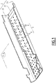
- Body 2 represented on the figure 1 and 3 is assumed to be placed on a horizontal surface.
- the body 2 extends along its length in a longitudinal direction.
- a longitudinal plane P1 is defined as being a vertical plane parallel to the longitudinal direction of the body 2.
- a transverse plane P2 is also defined as being a vertical plane orthogonal to the longitudinal plane P1.
- the side walls 24 and 26 are formed of metal profiles, which extend along their length parallel to the longitudinal direction of the body 2 and are assembled to each other.
- the bottom 22 is here formed of sections which extend parallel to a transverse direction of the body 2, that is to say parallel to a direction orthogonal to the longitudinal plane P1.
- bottom 22 thus formed is assembled to the side walls 24 and 26 and has geometric defects at the end of the manufacture of the box 2.
- the body 2 further comprises a floor 4, which is mounted on the bottom 22 of the body 2.
- the floor 4 comprises panels 6, which are connected to the body via leveling studs 8. More precisely , each of the panels 6 is leveled with several leveling studs 8, so that the floor 4 forms a flat surface when all the panels 6 are leveled.
- the structure of the leveling studs 8 is detailed later in this description.
- each of the panels 6 is leveled by means of six leveling studs 8. not detailed here.
- the panel 6 When a panel 6 has no cutouts, the panel 6 has a rectangular shape, arranged with its greatest transverse length to the body 2.
- the leveling studs 8 each have the same structure.
- a single leveling stud 8 is described below, using the figure 2 and 3 .
- the leveling pad 8 of the picture 2 includes a base 80, an adjusting rod 82, a guide piece 84 and a lock washer 86.
- the base 80 comprises an elastic block 802, a nut 804 and a sleeve 806.
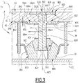
- the elastic block 802 is made of a vibration-absorbing material, such as an elastomer, and has a lower face 808 resting on the bottom 22 of body 2, as shown in the picture 3 .
- the elastic block 802 generally has a toric shape centered on an adjustment axis A80.
- the section of the torus, visible on the picture 3 is here an irregular polygon which comprises a horizontal segment corresponding to the lower face 808 of the elastic block 802 and an oblique segment which defines a support surface 810, of centered frustoconical shape on the axis of adjustment A80 and convergent in the direction of the bottom 22.
- the axis of adjustment A80 is orthogonal to the bottom 22 of the box 2.
- the nut 804 has a shape complementary to the bearing surface 810 of the elastic block 802 and is secured to the elastic block 802.
- the nut 804 has a threaded bore centered on the adjustment axis A80. It is understood that the nut 804 is not in direct contact with the bottom 22 of the body 2, but is separated from the body 2 by the elastic block 802, avoiding the transmission of vibrations from the body 2 to the nut 804 .
- the shirt 806, preferably made of metal, comprises a body 812 and two tabs 814.
- the body 812 here has a frustoconical shape, which cooperates with a peripheral surface 809 of the elastic block 802, the sleeve 806 being integral with the elastic block 802.
- the two lugs 814 are arranged diametrically opposite with respect to the adjustment axis A80. They are connected by a first end to the body 812 and each have, at a second end opposite the first end, a terminal zone 816 in which an eyelet 818 is formed.
- the eyelets 818 are each centered on a respective axis parallel to the adjustment axis A80.
- the adjustment rod 82 has a cylindrical shape of circular section centered on the adjustment axis A80.
- Rod 82 includes a lower end 820 and an upper end 822, opposite lower end 820.
- top In the present description, the terms “top”, “bottom”, lower”, “upper”, etc., relate to the orientation of the parts as shown in the figures, and do not prejudge any operation particular parts.
- the rod 82 comprises a collar 824, which has the shape of a disc centered on the adjustment axis A80 projecting from the adjustment rod 82 between the lower 820 and upper ends 822.
- the collar 824 has a radius R824, measured radially to axis A80, and a thickness E824, measured parallel to axis A80.
- the collar 824 delimits a lower portion 826 of the rod 82 between the collar 824 and the lower end 820, as well as an upper portion 828 between the collar 824 and the upper end 822.
- the lower 826 and upper 828 portions are threaded, the upper end 822 further comprising an indentation 830 made hollow and intended to cooperate with a tool not shown, so that an operator can rotate the adjustment rod 82 around the axis A80 in the direction of his choice.
- the imprint 830 is an imprint with hexagon socket and the tool is an allen key with hexagon. According to other examples, the imprint 830 is a six-lobe imprint similar to the so-called “Torx” imprints.
- the thread of the lower portion 826 is complementary to the thread of the nut 804.
- the collar 824 has a bearing face 832, which is oriented towards the upper end 822.
- a length D828 of the upper portion 828 is also defined as being the distance between the bearing surface 832 and the upper end 822, measured parallel to the adjustment axis A80.
- the guide piece 84 comprises a main body 840, which has the shape of a cup centered on the adjustment axis A80, is made in a plate, for example metal, and is produced, for example, by stamping.
- the main body 840 comprises four peripheral lugs 842 and a bottom 844.
- the lugs 842 are regularly distributed radially to the adjustment axis A80 at the periphery of the main body 840, and together define a first plane 848, orthogonal to the adjustment axis. A80 setting.
- the bottom 844 in the form of a disk of radius R844, has a central orifice 846 of axis A80.
- the bottom 844 defines a second plane 850, which is parallel to the first plane 848 and is offset from the first plane by a distance D844, measured parallel to the adjustment axis A80.
- the main body 840 provides a volume V844 for receiving the collar 824, the lower portion 826 of the adjustment rod 82 passing through the central orifice 846.
- Two of the peripheral lugs 842 diametrically opposite with respect to the adjustment axis A80, have a bore 852, with an axis parallel to the axis A80, while the other two peripheral lugs 842 which do not have a bore 852 carry each an 854 guide.
- the guides 854 here are cylindrical rods, each having a respective axis parallel to the adjustment axis A80, and are located on the same side of the first plane 848 facing the base 80.
- Each of the guides 854 slides in one of the eyelets 818 respective, so as to guide the guide piece 84 in translation with respect to the base 80 in a direction parallel to the adjustment axis A80.
- the guiding in translation of the guide piece 84 relative to the base 80 can be achieved with guides having other shapes than the guides 854 of the example illustrated, cooperating with complementary members different from the eyelets 818.
- Panel 6 visible in perspective on the picture 2 and in section on the picture 3 , has a lower face 60, oriented towards the bottom 22 of the body 2, and an upper face 62, opposite the lower face 60.
- the lower and upper faces 60 and 62 are parallel, and between them define a thickness E6 of the panel 6.
- the panel 6 further comprises a through hole 64, of circular section centered on the adjustment axis A80.
- the panel 6 has, on the side of the upper face 62, a recess, more particularly a counterbore, of circular shape and centered on the adjustment axis A80, the recess comprising a bottom 66.
- the bottom 66 has the shape of a circular crown and is located in a plane orthogonal to the adjustment axis A80.
- a depth E66 of the recess is defined as being the distance between the upper face 62 and the bottom 66, measured parallel to the adjustment axis A80.
- a radius R66 is also defined as being a radius of the bottom 66 measured radially to the adjustment axis A80.
- the locking washer 86 has the shape of a disc centered on the adjustment axis A80 and defining a radius R86, measured radially to the axis A80.
- the lock washer 86 has a lower face 860 and an upper face 862, which are parallel to each other and between them define a thickness E86 of the lock washer 86.
- the lock washer 86 also includes a bore central 864, which is threaded and is intended to cooperate with the upper portion 828 of the adjustment rod 82.
- the locking washer 86 further comprises two orifices 866, which open onto the upper face 862 and are diametrically opposed with respect to the adjustment axis A80.
- the holes 866 are provided to cooperate with a tool not shown, so that a user can screw or unscrew the locking washer 86 on the upper portion 828 of the adjustment rod 82.
- the guide piece 84 is fixed to the panel 6. More specifically, the peripheral lugs 842 rest on the underside 60 of the panel 6, and fastening members, not shown, cooperate with bores 852 to fix guide piece 84 to panel 6. assembled configuration, the collar 824 of the adjustment rod is housed in the reception volume V844 so as to prevent the translational movements of the rod 82 relative to the panel 6 while allowing the rotational movements of the adjustment rod 82 around the A80 axis. It is understood that the distance D844 of the recess 844 is equal, except for assembly clearance, to the thickness E824 of the collar 824. Similarly, the radius R844 of the recess 844 is greater than or equal to the radius R824 of the collar 824.
- the adjustment rod 82 is aligned with the through hole 64 of the panel, so that a user can access the recess 830 of the adjustment rod 82 to screw or unscrew the rod 82 into the nut 804 using a tool.
- the upper portion 828 of the rod 82 is housed in the through hole 64 of the panel 6, the upper end 822 being flush with the upper face 62 of the panel 6. More specifically, the length D828 of the upper portion 828 is equal to the thickness E6 of panel 6.
- the guides 854, cooperating with the eyelets 818, prevent the rotational movements of the base 80 with respect to the guide part 84 and with respect to the panel 6 on which the part 84 is fixed. Similarly, only the translation movements of the base 80 relative to the guide piece 84, and therefore relative to the panel 6, are authorized. It is understood that the rotational movements of the adjustment rod 82, the lower portion 826 of which cooperates with the nut 804 of the base, result in translational movements of the base 80 parallel to the adjustment axis A80 .
- the guides 854 of the guide piece 84, cooperating with the eyelets 818, prevent the base 80 from rotating “idle” when the adjustment rod 82 is screwed or unscrewed by an operator.
- the operator can thus, by screwing or unscrewing the adjustment rod 82, bring the base 80 closer to or further away from the collar 824. In other words, the operator can adjust the height of the leveling stud 8.
- the thickness E86 is equal to the depth E66 of the recess of the panel 6, which means that in the blocked configuration, the face top 862 of lock washer 86 is flush with top face 62 of panel 6.
- a step a) the guide piece 84 is fixed under the lower face 60 of the panel 6, the upper portion 828 of the rod 82 passing through the through hole 64 of the panel 6, the lower portion 826 of the rod 82 passing through the central orifice 846 of the guide piece 84 and the collar 824 being housed in the recess 844 of the guide piece 84.
- the base 80 is put in place so that the guides 854 cooperate with the eyelets 818 and that, together, the lower portion 826 cooperates with the nut 804 of the base 80.
- step a) the base 80, the adjustment rod 82 and the guide piece 84 are positioned under the lower face 60 of the panel 6, the panel 6 being able to be moved by an operator.
- a step b) of the assembly method the panel 6 is placed on the bottom 22 of the body 2, the leveling studs being located between the panel 6 and the bottom 22.
- the bottom 22 of the body 2 not being perfectly flat, the bases 80 of some of the leveling studs 8 rest on the bottom 22, while the bases of other studs 8 are not in contact with the bottom 22.
- step c) the operator adjusts the height of each leveling stud 8 if necessary by screwing or unscrewing the adjustment rod 82 in the nut 804 by means of a tool cooperating with the recess 830, until panel 6 is in the desired position.
- the panels 6 of the box 2 are coplanar, so that the floor 2 is flat, and horizontal when the box 2 is horizontal.
- step d the operator locks the adjustment rod 82 by screwing the locking washer 86 onto the upper portion 828 of the rod 82, until the locking washer 86 is tightened on the panel 6.
- step d the upper face 862 of the washer 86 is flush with the upper face 62 of the panel 6.
Landscapes
- Engineering & Computer Science (AREA)
- Mechanical Engineering (AREA)
- Chemical & Material Sciences (AREA)
- Combustion & Propulsion (AREA)
- Transportation (AREA)
- Life Sciences & Earth Sciences (AREA)
- Wood Science & Technology (AREA)
- Connection Of Plates (AREA)
- Vibration Prevention Devices (AREA)
Applications Claiming Priority (1)
| Application Number | Priority Date | Filing Date | Title |
|---|---|---|---|
| FR2001530A FR3107242B1 (fr) | 2020-02-17 | 2020-02-17 | Plot de nivellement de plancher de véhicule, notamment ferroviaire, plancher de véhicule et caisse de véhicule comprenant un tel plot |
Publications (2)
| Publication Number | Publication Date |
|---|---|
| EP3865367A1 EP3865367A1 (fr) | 2021-08-18 |
| EP3865367B1 true EP3865367B1 (fr) | 2022-06-22 |
Family
ID=70228308
Family Applications (1)
| Application Number | Title | Priority Date | Filing Date |
|---|---|---|---|
| EP21157061.9A Active EP3865367B1 (fr) | 2020-02-17 | 2021-02-15 | Plot de nivellement de plancher de véhicule, notamment ferroviaire, plancher de véhicule et caisse de véhicule comprenant un tel plot |
Country Status (4)
| Country | Link |
|---|---|
| EP (1) | EP3865367B1 (pl) |
| ES (1) | ES2925281T3 (pl) |
| FR (1) | FR3107242B1 (pl) |
| PL (1) | PL3865367T3 (pl) |
Families Citing this family (1)
| Publication number | Priority date | Publication date | Assignee | Title |
|---|---|---|---|---|
| EP4527710A1 (de) * | 2023-09-25 | 2025-03-26 | Siemens Mobility GmbH | Befestigungsvorrichtung für ein fussbodenelement |
Family Cites Families (2)
| Publication number | Priority date | Publication date | Assignee | Title |
|---|---|---|---|---|
| DE19927006C2 (de) * | 1999-06-09 | 2001-05-10 | Daimler Chrysler Ag | Fußboden für Fahrzeuge, insbesondere Schienenfahrzeuge zur Personenbeförderung |
| EP2399797B1 (fr) | 2010-06-22 | 2017-01-11 | Constellium Valais SA | Élément de liaison élastique destiné au montage flottant d'un plancher interne, panneau de plancher interne équipé d'une pluralité d'éléments de liaison élastique et procédé de montage flottant d'un plancher |
-
2020
- 2020-02-17 FR FR2001530A patent/FR3107242B1/fr not_active Expired - Fee Related
-
2021
- 2021-02-15 ES ES21157061T patent/ES2925281T3/es active Active
- 2021-02-15 PL PL21157061.9T patent/PL3865367T3/pl unknown
- 2021-02-15 EP EP21157061.9A patent/EP3865367B1/fr active Active
Also Published As
| Publication number | Publication date |
|---|---|
| FR3107242B1 (fr) | 2023-06-30 |
| ES2925281T3 (es) | 2022-10-14 |
| FR3107242A1 (fr) | 2021-08-20 |
| PL3865367T3 (pl) | 2022-10-17 |
| EP3865367A1 (fr) | 2021-08-18 |
Similar Documents
| Publication | Publication Date | Title |
|---|---|---|
| EP1089890A1 (fr) | Attache superieure de jambe macpherson | |
| EP3865367B1 (fr) | Plot de nivellement de plancher de véhicule, notamment ferroviaire, plancher de véhicule et caisse de véhicule comprenant un tel plot | |
| EP3313716B1 (fr) | Dispositif de fixation destiné à être monté dans une cuvette, typiquement de roue de secours, d'un plancher, notamment arrière, de véhicule automobile | |
| EP2170685A1 (fr) | Procede de montage d'un pare-chocs sur une structure de vehicule automobile. | |
| WO2020016347A1 (fr) | Butée de suspension de véhicule automobile | |
| WO2017085367A1 (fr) | Fixation de siege sur plancher composite de vehicule automobile | |
| FR2759752A1 (fr) | Attache non porteuse pour ensemble ressort-amortisseur de vehicule automobile | |
| CH677011A5 (pl) | ||
| EP3154843A1 (fr) | Assemblage d'un élément de structure de véhicule automobile et d'un élément fonctionnel | |
| EP1681223A1 (fr) | Dispositif de blocage en position d'une colonne de direction réglable de véhicule automobile, ensemble comprenant un tel dispositif, et véhicule automobile comprenant un tel ensemble | |
| FR3119826A1 (fr) | Ensemble comprenant un élément de carénage destiné à être monté sous caisse dans un véhicule automobile, et au moins une pièce de fixation de l’élément de carénage | |
| FR2920365A1 (fr) | Agencement de fixation pour fixer un phare sur un element d'habillage d'un vehicule | |
| FR2935338A1 (fr) | Structure de vehicule automobile et vehicule automobile comportant une telle structure | |
| FR2672548A1 (fr) | Dispositif de fixation d'une extremite d'amortisseur telescopique sur la caisse d'un vehicule automobile. | |
| FR3066744A1 (fr) | Boite d'essieu pour un vehicule ferroviaire | |
| EP2509811A1 (fr) | Structure de vehicule automobile et vehicule automobile comportant une telle structure | |
| FR3122637A1 (fr) | Dispositif de guidage pour une fixation dans un véhicule automobile et agencement comprenant un tel dispositif. | |
| FR2671147A1 (fr) | Dispositif d'immobilisation de deux pieces assemblees par pression de l'une sur l'autre, en particulier pour vehicule automobile. | |
| FR3123871A1 (fr) | Support de fixation d’un panneau d’habillage à une caisse de véhicule de transport, sous-ensemble de montage, kit de fixation, caisse et véhicule comprenant un tel support et procédé de montage associé | |
| FR3154166A1 (fr) | Support de parechocs pour véhicule automobile | |
| FR3140337A1 (fr) | Dispositif de fixation pour un capot de caisse modulaire de véhicule ferroviaire, caisse modulaire, kit de fixation et procédé de fixation associés | |
| FR3106117A1 (fr) | Support de suspension pour véhicule automobile | |
| FR3123870A1 (fr) | Ensemble de garnissage d’une caisse de véhicule, notamment ferroviaire | |
| FR3137610A1 (fr) | Sous-ensemble filtrant pour un Assemblage de butée SUPÉRIEURE d’une jambe de suspension de véhicule automobile, assemblage, jambe de suspension et procédé d’assemblage associés | |
| FR3142960A1 (fr) | Dispositif d’éclairage pour projecteur de véhicule automobile. |
Legal Events
| Date | Code | Title | Description |
|---|---|---|---|
| PUAI | Public reference made under article 153(3) epc to a published international application that has entered the european phase |
Free format text: ORIGINAL CODE: 0009012 |
|
| STAA | Information on the status of an ep patent application or granted ep patent |
Free format text: STATUS: THE APPLICATION HAS BEEN PUBLISHED |
|
| STAA | Information on the status of an ep patent application or granted ep patent |
Free format text: STATUS: REQUEST FOR EXAMINATION WAS MADE |
|
| AK | Designated contracting states |
Kind code of ref document: A1 Designated state(s): AL AT BE BG CH CY CZ DE DK EE ES FI FR GB GR HR HU IE IS IT LI LT LU LV MC MK MT NL NO PL PT RO RS SE SI SK SM TR |
|
| 17P | Request for examination filed |
Effective date: 20210810 |
|
| RBV | Designated contracting states (corrected) |
Designated state(s): AL AT BE BG CH CY CZ DE DK EE ES FI FR GB GR HR HU IE IS IT LI LT LU LV MC MK MT NL NO PL PT RO RS SE SI SK SM TR |
|
| RIC1 | Information provided on ipc code assigned before grant |
Ipc: B62D 31/02 20060101ALI20211216BHEP Ipc: B61D 17/10 20060101AFI20211216BHEP |
|
| GRAP | Despatch of communication of intention to grant a patent |
Free format text: ORIGINAL CODE: EPIDOSNIGR1 |
|
| STAA | Information on the status of an ep patent application or granted ep patent |
Free format text: STATUS: GRANT OF PATENT IS INTENDED |
|
| INTG | Intention to grant announced |
Effective date: 20220128 |
|
| GRAS | Grant fee paid |
Free format text: ORIGINAL CODE: EPIDOSNIGR3 |
|
| GRAA | (expected) grant |
Free format text: ORIGINAL CODE: 0009210 |
|
| STAA | Information on the status of an ep patent application or granted ep patent |
Free format text: STATUS: THE PATENT HAS BEEN GRANTED |
|
| AK | Designated contracting states |
Kind code of ref document: B1 Designated state(s): AL AT BE BG CH CY CZ DE DK EE ES FI FR GB GR HR HU IE IS IT LI LT LU LV MC MK MT NL NO PL PT RO RS SE SI SK SM TR |
|
| REG | Reference to a national code |
Ref country code: GB Ref legal event code: FG4D Free format text: NOT ENGLISH |
|
| RIN1 | Information on inventor provided before grant (corrected) |
Inventor name: COURCIMEAUX, ERIC |
|
| REG | Reference to a national code |
Ref country code: CH Ref legal event code: EP |
|
| REG | Reference to a national code |
Ref country code: DE Ref legal event code: R096 Ref document number: 602021000150 Country of ref document: DE |
|
| REG | Reference to a national code |
Ref country code: AT Ref legal event code: REF Ref document number: 1499608 Country of ref document: AT Kind code of ref document: T Effective date: 20220715 |
|
| REG | Reference to a national code |
Ref country code: IE Ref legal event code: FG4D Free format text: LANGUAGE OF EP DOCUMENT: FRENCH |
|
| REG | Reference to a national code |
Ref country code: SE Ref legal event code: TRGR |
|
| REG | Reference to a national code |
Ref country code: LT Ref legal event code: MG9D |
|
| REG | Reference to a national code |
Ref country code: ES Ref legal event code: FG2A Ref document number: 2925281 Country of ref document: ES Kind code of ref document: T3 Effective date: 20221014 |
|
| REG | Reference to a national code |
Ref country code: NL Ref legal event code: MP Effective date: 20220622 |
|
| PG25 | Lapsed in a contracting state [announced via postgrant information from national office to epo] |
Ref country code: NO Free format text: LAPSE BECAUSE OF FAILURE TO SUBMIT A TRANSLATION OF THE DESCRIPTION OR TO PAY THE FEE WITHIN THE PRESCRIBED TIME-LIMIT Effective date: 20220922 Ref country code: LT Free format text: LAPSE BECAUSE OF FAILURE TO SUBMIT A TRANSLATION OF THE DESCRIPTION OR TO PAY THE FEE WITHIN THE PRESCRIBED TIME-LIMIT Effective date: 20220622 Ref country code: HR Free format text: LAPSE BECAUSE OF FAILURE TO SUBMIT A TRANSLATION OF THE DESCRIPTION OR TO PAY THE FEE WITHIN THE PRESCRIBED TIME-LIMIT Effective date: 20220622 Ref country code: GR Free format text: LAPSE BECAUSE OF FAILURE TO SUBMIT A TRANSLATION OF THE DESCRIPTION OR TO PAY THE FEE WITHIN THE PRESCRIBED TIME-LIMIT Effective date: 20220923 Ref country code: FI Free format text: LAPSE BECAUSE OF FAILURE TO SUBMIT A TRANSLATION OF THE DESCRIPTION OR TO PAY THE FEE WITHIN THE PRESCRIBED TIME-LIMIT Effective date: 20220622 Ref country code: BG Free format text: LAPSE BECAUSE OF FAILURE TO SUBMIT A TRANSLATION OF THE DESCRIPTION OR TO PAY THE FEE WITHIN THE PRESCRIBED TIME-LIMIT Effective date: 20220922 |
|
| REG | Reference to a national code |
Ref country code: AT Ref legal event code: MK05 Ref document number: 1499608 Country of ref document: AT Kind code of ref document: T Effective date: 20220622 |
|
| PG25 | Lapsed in a contracting state [announced via postgrant information from national office to epo] |
Ref country code: RS Free format text: LAPSE BECAUSE OF FAILURE TO SUBMIT A TRANSLATION OF THE DESCRIPTION OR TO PAY THE FEE WITHIN THE PRESCRIBED TIME-LIMIT Effective date: 20220622 Ref country code: LV Free format text: LAPSE BECAUSE OF FAILURE TO SUBMIT A TRANSLATION OF THE DESCRIPTION OR TO PAY THE FEE WITHIN THE PRESCRIBED TIME-LIMIT Effective date: 20220622 |
|
| PG25 | Lapsed in a contracting state [announced via postgrant information from national office to epo] |
Ref country code: NL Free format text: LAPSE BECAUSE OF FAILURE TO SUBMIT A TRANSLATION OF THE DESCRIPTION OR TO PAY THE FEE WITHIN THE PRESCRIBED TIME-LIMIT Effective date: 20220622 |
|
| PG25 | Lapsed in a contracting state [announced via postgrant information from national office to epo] |
Ref country code: SM Free format text: LAPSE BECAUSE OF FAILURE TO SUBMIT A TRANSLATION OF THE DESCRIPTION OR TO PAY THE FEE WITHIN THE PRESCRIBED TIME-LIMIT Effective date: 20220622 Ref country code: SK Free format text: LAPSE BECAUSE OF FAILURE TO SUBMIT A TRANSLATION OF THE DESCRIPTION OR TO PAY THE FEE WITHIN THE PRESCRIBED TIME-LIMIT Effective date: 20220622 Ref country code: RO Free format text: LAPSE BECAUSE OF FAILURE TO SUBMIT A TRANSLATION OF THE DESCRIPTION OR TO PAY THE FEE WITHIN THE PRESCRIBED TIME-LIMIT Effective date: 20220622 Ref country code: PT Free format text: LAPSE BECAUSE OF FAILURE TO SUBMIT A TRANSLATION OF THE DESCRIPTION OR TO PAY THE FEE WITHIN THE PRESCRIBED TIME-LIMIT Effective date: 20221024 Ref country code: EE Free format text: LAPSE BECAUSE OF FAILURE TO SUBMIT A TRANSLATION OF THE DESCRIPTION OR TO PAY THE FEE WITHIN THE PRESCRIBED TIME-LIMIT Effective date: 20220622 Ref country code: CZ Free format text: LAPSE BECAUSE OF FAILURE TO SUBMIT A TRANSLATION OF THE DESCRIPTION OR TO PAY THE FEE WITHIN THE PRESCRIBED TIME-LIMIT Effective date: 20220622 Ref country code: AT Free format text: LAPSE BECAUSE OF FAILURE TO SUBMIT A TRANSLATION OF THE DESCRIPTION OR TO PAY THE FEE WITHIN THE PRESCRIBED TIME-LIMIT Effective date: 20220622 |
|
| PG25 | Lapsed in a contracting state [announced via postgrant information from national office to epo] |
Ref country code: IS Free format text: LAPSE BECAUSE OF FAILURE TO SUBMIT A TRANSLATION OF THE DESCRIPTION OR TO PAY THE FEE WITHIN THE PRESCRIBED TIME-LIMIT Effective date: 20221022 |
|
| REG | Reference to a national code |
Ref country code: DE Ref legal event code: R097 Ref document number: 602021000150 Country of ref document: DE |
|
| PG25 | Lapsed in a contracting state [announced via postgrant information from national office to epo] |
Ref country code: AL Free format text: LAPSE BECAUSE OF FAILURE TO SUBMIT A TRANSLATION OF THE DESCRIPTION OR TO PAY THE FEE WITHIN THE PRESCRIBED TIME-LIMIT Effective date: 20220622 |
|
| PG25 | Lapsed in a contracting state [announced via postgrant information from national office to epo] |
Ref country code: DK Free format text: LAPSE BECAUSE OF FAILURE TO SUBMIT A TRANSLATION OF THE DESCRIPTION OR TO PAY THE FEE WITHIN THE PRESCRIBED TIME-LIMIT Effective date: 20220622 |
|
| PLBE | No opposition filed within time limit |
Free format text: ORIGINAL CODE: 0009261 |
|
| STAA | Information on the status of an ep patent application or granted ep patent |
Free format text: STATUS: NO OPPOSITION FILED WITHIN TIME LIMIT |
|
| 26N | No opposition filed |
Effective date: 20230323 |
|
| PG25 | Lapsed in a contracting state [announced via postgrant information from national office to epo] |
Ref country code: SI Free format text: LAPSE BECAUSE OF FAILURE TO SUBMIT A TRANSLATION OF THE DESCRIPTION OR TO PAY THE FEE WITHIN THE PRESCRIBED TIME-LIMIT Effective date: 20220622 |
|
| PG25 | Lapsed in a contracting state [announced via postgrant information from national office to epo] |
Ref country code: MC Free format text: LAPSE BECAUSE OF FAILURE TO SUBMIT A TRANSLATION OF THE DESCRIPTION OR TO PAY THE FEE WITHIN THE PRESCRIBED TIME-LIMIT Effective date: 20220622 |
|
| REG | Reference to a national code |
Ref country code: BE Ref legal event code: MM Effective date: 20230228 |
|
| PG25 | Lapsed in a contracting state [announced via postgrant information from national office to epo] |
Ref country code: LU Free format text: LAPSE BECAUSE OF NON-PAYMENT OF DUE FEES Effective date: 20230215 |
|
| P01 | Opt-out of the competence of the unified patent court (upc) registered |
Effective date: 20231025 |
|
| REG | Reference to a national code |
Ref country code: IE Ref legal event code: MM4A |
|
| PG25 | Lapsed in a contracting state [announced via postgrant information from national office to epo] |
Ref country code: IE Free format text: LAPSE BECAUSE OF NON-PAYMENT OF DUE FEES Effective date: 20230215 |
|
| PG25 | Lapsed in a contracting state [announced via postgrant information from national office to epo] |
Ref country code: BE Free format text: LAPSE BECAUSE OF NON-PAYMENT OF DUE FEES Effective date: 20230228 |
|
| PG25 | Lapsed in a contracting state [announced via postgrant information from national office to epo] |
Ref country code: BG Free format text: LAPSE BECAUSE OF FAILURE TO SUBMIT A TRANSLATION OF THE DESCRIPTION OR TO PAY THE FEE WITHIN THE PRESCRIBED TIME-LIMIT Effective date: 20220622 |
|
| PG25 | Lapsed in a contracting state [announced via postgrant information from national office to epo] |
Ref country code: BG Free format text: LAPSE BECAUSE OF FAILURE TO SUBMIT A TRANSLATION OF THE DESCRIPTION OR TO PAY THE FEE WITHIN THE PRESCRIBED TIME-LIMIT Effective date: 20220622 |
|
| PGFP | Annual fee paid to national office [announced via postgrant information from national office to epo] |
Ref country code: DE Payment date: 20250218 Year of fee payment: 5 |
|
| PGFP | Annual fee paid to national office [announced via postgrant information from national office to epo] |
Ref country code: SE Payment date: 20250218 Year of fee payment: 5 |
|
| PGFP | Annual fee paid to national office [announced via postgrant information from national office to epo] |
Ref country code: CH Payment date: 20250301 Year of fee payment: 5 |
|
| PGFP | Annual fee paid to national office [announced via postgrant information from national office to epo] |
Ref country code: FR Payment date: 20250224 Year of fee payment: 5 Ref country code: PL Payment date: 20250207 Year of fee payment: 5 |
|
| PGFP | Annual fee paid to national office [announced via postgrant information from national office to epo] |
Ref country code: IT Payment date: 20250224 Year of fee payment: 5 |
|
| PGFP | Annual fee paid to national office [announced via postgrant information from national office to epo] |
Ref country code: ES Payment date: 20250331 Year of fee payment: 5 |
|
| PG25 | Lapsed in a contracting state [announced via postgrant information from national office to epo] |
Ref country code: CY Free format text: LAPSE BECAUSE OF FAILURE TO SUBMIT A TRANSLATION OF THE DESCRIPTION OR TO PAY THE FEE WITHIN THE PRESCRIBED TIME-LIMIT; INVALID AB INITIO Effective date: 20210215 |
|
| PG25 | Lapsed in a contracting state [announced via postgrant information from national office to epo] |
Ref country code: HU Free format text: LAPSE BECAUSE OF FAILURE TO SUBMIT A TRANSLATION OF THE DESCRIPTION OR TO PAY THE FEE WITHIN THE PRESCRIBED TIME-LIMIT; INVALID AB INITIO Effective date: 20210215 |
|
| GBPC | Gb: european patent ceased through non-payment of renewal fee |
Effective date: 20250215 |
|
| PG25 | Lapsed in a contracting state [announced via postgrant information from national office to epo] |
Ref country code: TR Free format text: LAPSE BECAUSE OF FAILURE TO SUBMIT A TRANSLATION OF THE DESCRIPTION OR TO PAY THE FEE WITHIN THE PRESCRIBED TIME-LIMIT Effective date: 20220622 |
|
| PG25 | Lapsed in a contracting state [announced via postgrant information from national office to epo] |
Ref country code: GB Free format text: LAPSE BECAUSE OF NON-PAYMENT OF DUE FEES Effective date: 20250215 |
|
| REG | Reference to a national code |
Ref country code: CH Ref legal event code: U11 Free format text: ST27 STATUS EVENT CODE: U-0-0-U10-U11 (AS PROVIDED BY THE NATIONAL OFFICE) Effective date: 20260301 |