EP3865304B1 - Vérification d'image déterministe - Google Patents
Vérification d'image déterministe Download PDFInfo
- Publication number
- EP3865304B1 EP3865304B1 EP20157140.3A EP20157140A EP3865304B1 EP 3865304 B1 EP3865304 B1 EP 3865304B1 EP 20157140 A EP20157140 A EP 20157140A EP 3865304 B1 EP3865304 B1 EP 3865304B1
- Authority
- EP
- European Patent Office
- Prior art keywords
- image
- deviations
- regions
- computer
- printed
- Prior art date
- Legal status (The legal status is an assumption and is not a legal conclusion. Google has not performed a legal analysis and makes no representation as to the accuracy of the status listed.)
- Active
Links
- 238000007689 inspection Methods 0.000 title description 36
- 238000000034 method Methods 0.000 claims description 52
- 238000012545 processing Methods 0.000 claims description 20
- 230000007547 defect Effects 0.000 claims description 6
- 239000002699 waste material Substances 0.000 claims description 6
- 230000002950 deficient Effects 0.000 claims 2
- 239000000758 substrate Substances 0.000 claims 1
- 238000011161 development Methods 0.000 description 11
- 230000018109 developmental process Effects 0.000 description 11
- 238000004364 calculation method Methods 0.000 description 6
- 238000011156 evaluation Methods 0.000 description 4
- 230000008030 elimination Effects 0.000 description 3
- 238000003379 elimination reaction Methods 0.000 description 3
- 238000011835 investigation Methods 0.000 description 2
- 239000000463 material Substances 0.000 description 2
- 230000008092 positive effect Effects 0.000 description 2
- 238000003908 quality control method Methods 0.000 description 2
- 230000006978 adaptation Effects 0.000 description 1
- 238000013459 approach Methods 0.000 description 1
- 230000015572 biosynthetic process Effects 0.000 description 1
- 230000001427 coherent effect Effects 0.000 description 1
- 238000010276 construction Methods 0.000 description 1
- 238000011143 downstream manufacturing Methods 0.000 description 1
- 238000005457 optimization Methods 0.000 description 1
- 238000007781 pre-processing Methods 0.000 description 1
- 238000012360 testing method Methods 0.000 description 1
Images


Classifications
-
- B—PERFORMING OPERATIONS; TRANSPORTING
- B41—PRINTING; LINING MACHINES; TYPEWRITERS; STAMPS
- B41F—PRINTING MACHINES OR PRESSES
- B41F33/00—Indicating, counting, warning, control or safety devices
- B41F33/0036—Devices for scanning or checking the printed matter for quality control
-
- G—PHYSICS
- G06—COMPUTING; CALCULATING OR COUNTING
- G06T—IMAGE DATA PROCESSING OR GENERATION, IN GENERAL
- G06T1/00—General purpose image data processing
- G06T1/20—Processor architectures; Processor configuration, e.g. pipelining
-
- G—PHYSICS
- G06—COMPUTING; CALCULATING OR COUNTING
- G06T—IMAGE DATA PROCESSING OR GENERATION, IN GENERAL
- G06T7/00—Image analysis
- G06T7/0002—Inspection of images, e.g. flaw detection
- G06T7/0004—Industrial image inspection
- G06T7/001—Industrial image inspection using an image reference approach
-
- G—PHYSICS
- G06—COMPUTING; CALCULATING OR COUNTING
- G06T—IMAGE DATA PROCESSING OR GENERATION, IN GENERAL
- G06T7/00—Image analysis
- G06T7/10—Segmentation; Edge detection
- G06T7/11—Region-based segmentation
-
- G—PHYSICS
- G06—COMPUTING; CALCULATING OR COUNTING
- G06V—IMAGE OR VIDEO RECOGNITION OR UNDERSTANDING
- G06V10/00—Arrangements for image or video recognition or understanding
- G06V10/40—Extraction of image or video features
- G06V10/50—Extraction of image or video features by performing operations within image blocks; by using histograms, e.g. histogram of oriented gradients [HoG]; by summing image-intensity values; Projection analysis
-
- G—PHYSICS
- G06—COMPUTING; CALCULATING OR COUNTING
- G06V—IMAGE OR VIDEO RECOGNITION OR UNDERSTANDING
- G06V10/00—Arrangements for image or video recognition or understanding
- G06V10/98—Detection or correction of errors, e.g. by rescanning the pattern or by human intervention; Evaluation of the quality of the acquired patterns
- G06V10/993—Evaluation of the quality of the acquired pattern
-
- G—PHYSICS
- G06—COMPUTING; CALCULATING OR COUNTING
- G06T—IMAGE DATA PROCESSING OR GENERATION, IN GENERAL
- G06T2207/00—Indexing scheme for image analysis or image enhancement
- G06T2207/30—Subject of image; Context of image processing
- G06T2207/30108—Industrial image inspection
- G06T2207/30144—Printing quality
-
- G—PHYSICS
- G06—COMPUTING; CALCULATING OR COUNTING
- G06T—IMAGE DATA PROCESSING OR GENERATION, IN GENERAL
- G06T2207/00—Indexing scheme for image analysis or image enhancement
- G06T2207/30—Subject of image; Context of image processing
- G06T2207/30168—Image quality inspection
Definitions
- the invention is concerned with a method for inspecting printed products, the inspection being carried out as a function of the estimated cost of evaluating potential image defects found.
- the invention lies in the technical field of digital quality control.
- image inspection processes When producing print products in printing machines of the appropriate size, quality control is often carried out using image inspection processes. These methods mostly use image acquisition systems whose image sensors, mostly cameras, are attached inside the printing press after the last printing unit. The inspection must always be fast enough to keep up with the printing speed. Therefore, there is only a firmly defined time window available for the inspection of a printed product, such as a printed sheet. If there are now very many or very large printing errors on a printed sheet, the predefined period of time which is available for the analysis and evaluation of printing errors found is exceeded. In most cases, image inspection not only includes finding deviations from a so-called good or reference image, but also analyzing the errors found to ensure that the deviations found are actually printing errors and not, for example, errors in the image acquisition system .
- the investigation of the printing errors found but not yet analyzed is carried out anyway, which leads to an uncontrolled time delay in the image inspection, since the inspection is still processing printed sheets while the printing press has long been producing the next printed products.
- the image inspection is simply aborted when the time per print sheet has elapsed, so that printing errors that have not been analyzed are not found. Since both approaches degrade the quality of the image inspection process, a way to prevent this is sought. So a solution has to be found so that the image inspection can be carried out within the specified time per print sheet is not exceeded and nevertheless all printing errors that occur are recognized as such.
- the European patent application EP 3 456 535 A1 discloses a method for waste management in a printing material processing machine by means of a computer Print images from the digital reference, the incorrectly recognized print products are ejected, and which is characterized in that waste profiles are created which contain parameters to which specific actions are assigned and for print images that deviate from the digital reference within the framework of the image inspection, depending on the parameters specific actions are carried out, with different terminals being controlled depending on the specific actions.
- the object of the present invention is therefore to find a method for image inspection of printed products which overcomes the disadvantages known from the prior art and enables reliable image inspection.
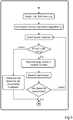
- the object is achieved according to the invention by the features of claim 1, namely by a method for the inspection of printed products of a printing material processing machine by means of a computer, whereby printed products produced are recorded, digitized and examined by the computer for possible errors by means of at least one image sensor, errors in the printed products are determined by the computer by comparing the captured, digitized print image with a digital reference image and evaluating any deviations that occur, and faulty print products are marked and ejected accordingly, which is characterized in that the computer undertakes a spatial division of each digitized print product into areas with deviations The time required to examine each of these areas is calculated and the examination of a digitized print product is terminated if the time required to examine the areas is a v exceeds the specified time value per digitized print product.
- a preferred development of the method according to the invention is that the computer calculates the time required to examine each of the areas for each area directly before the examination of this area and terminates the examination of the current, digitized print product if the specified time value is exceeded, with the deviations areas that have not yet been examined are marked as printing errors.
- This procedure is the most efficient way of a dynamic image inspection, because here all deviations found in the print image are processed one after the other and the calculation of the time required for the area currently to be processed always takes place directly before the start of the calculation, which means that the image inspection may be aborted if exceeded of the specified time frame for the image inspection of the current print image really only takes place precisely when the algorithm is shortly before this target time value expires.
- a further preferred development of the method according to the invention is that the computer calculates the time required for the examination of all before the examination begins and only examines the areas of the current, digitized print product for which there is enough time with regard to the specified time value, whereby the deviations are not examined areas are marked as printing errors.
- the calculation of the time period can of course also be carried out directly after the division into the areas with the respective deviations and then simply by means of a comparison between the specified time frame or Time value and total time expenditure for the individual areas determine how many areas can be processed. Overall, this procedure may be somewhat more imprecise, but it has the advantage that the order in which the respective areas are to be examined more closely, based on the then already calculated time expenditure for the individual areas can be carried out.
- a further preferred development of the method according to the invention is that the comparison of the captured, digitized print image with a digital reference image takes place by forming the difference between the print and reference image and evaluating the resulting difference image.
- the formation of a difference image between the captured digitized print image and a digital reference image is one of the simplest procedures for determining any deviations and thus existing printing errors , is, or a taught-in printed good image, is irrelevant for the present inventive method.
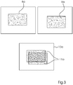
- Another preferred development of the method according to the invention is that the spatial division of each digitized printed product into areas with deviations is carried out by isolating areas with deviations in the difference image when evaluating the difference image. Areas with deviations can be identified very easily in the difference image, so that the spatial division of the digitized print product can be carried out very efficiently.
- Another preferred development of the method according to the invention is that areas with deviations in the differential image with a low degree of filling are divided into individual, smaller areas and evaluated and / or the computer carries out a position compensation for these areas in the captured, digitized print image and / or reference image.
- the degree of filling is defined by the ratio of pixels with deviations in the difference image to the total number of pixels in the surrounding area of the deviation.
- a low degree of filling thus means that existing objects in the print image or reference image differ only slightly or differ from one another. This often happens through slight shifts of the objects in the captured and digitized print image compared to the same objects in the reference image, whereby these shifts can be corrected by means of a bearing compensation.
- the deviation in the difference image is also very large in the event of a shift, but only with a small area, i.e. a low degree of filling, In this case, it is also advisable to subdivide this very large area with the deviation in the difference image into individual smaller areas and to evaluate these smaller areas individually.
- Another preferred development of the method according to the invention is that areas with deviations in the differential image with a high degree of filling are not further evaluated and these deviations are marked as printing errors. If, on the other hand, such areas occur with a high degree of filling, this means that there have been very strong deviations between individual objects in the print image and the reference image, which cannot be corrected by a warehouse as compensation. This can happen, for example, if the wrong reference image or a wrong part of the reference image is compared with the respective print image. In this case, a further investigation of this deviation with regard to a printing error is unnecessary, since it is clear that it is either a massive printing error or, in the case of the wrong reference image or the wrong part of the reference image, a massive error in the image inspection system or process is present.
- a further preferred development of the method according to the invention is that the examination of the produced image products is carried out by the computer in two process steps, the first step requiring a slightly fluctuating period of time, while the second step, which includes the examination of the divided areas, with regard to the The time required is highly variable, so that the calculation of the time required for the examination is only carried out for the second step.
- the first step which is relatively constant, the difference image is formed and further parts of the image inspection process are carried out. Since the time period for this first part is correspondingly constant, there is no need to calculate this time period since it is known anyway.
- the processing of the divided areas of the differential image or of the print and reference image is very variable and can accordingly be calculated according to the invention.
- the infrastructure available for evaluation by means of the computer is decisive for the variability of the second process step.
- serial processing using a CPO is also much easier and more precise calculate as a parallel processing using a GPO.
- the existing infrastructure of the computer and its use thus also have a decisive influence on the implementation of the method according to the invention.
- the method is carried out separately for each at least one image sensor, with the time reserves that arise during the processing of a digitized print product of an image sensor being used variably by the computer for the processing of digitized print products, possibly other image sensors can be.
- the image inspection system or image acquisition system to be used also usually consists of several image sensors or cameras and the corresponding method according to the invention must therefore be carried out separately for each of these image sensors, it can happen that depending on the type of deviation to be examined and the infrastructure available the processing of a print image captured by a certain screen, time reserves arise because one has not exhausted the entire available time frame. These time reserves can then, if necessary, be used when carrying out the method according to the invention for another image sensor and its captured and digitized print image. These time reserves are allocated by the computer used.
- the at least one image sensor is part of an inline inspection system of a sheet-fed printing machine and this examines the printed sheets produced as printed products in the sheet-fed printing machine, with incorrectly marked printed sheets being ejected using a waste gate.
- the method according to the invention is preferably used for inline inspection systems which are part of a sheet-fed printing machine and which evaluate corresponding printed sheets as printed products.
- This also has the advantage that the incorrectly marked printed sheets can then also be automatically ejected immediately by means of a waste gate that is usually present in such sheet-fed printing machines.
- there is also a simple marking for example by means of a strip, in the boom, in which case this accordingly marked print sheets have to be ejected either by hand from the printer or automatically in a downstream process.
- Figure 1 shows an example of an image acquisition system 2 which uses the method according to the invention. It consists of at least one image sensor 5, usually a camera 5, which is integrated into the sheet-fed printing press 4. The at least one camera 5 records the print images generated by the printing press 4 and sends the data to a computer 3, 6 for evaluation.
- This computer 3, 6 can be its own separate computer 6, for example one or more specialized image processing computers 6, or it can also be identical to the control computer 3 of the printing press 4.
- At least the control computer 3 of the printing press 4 has a display 7 on which the results of the image inspection are displayed to the user 1.
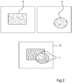
- difference image 10 two large interrelated deviations 11, which in Figure 2 are also marked, each of which has a high degree of filling.
- the difference image 10 is created by subtracting the desired / reference image 8, which is shown in Figure 2 is shown at the top left and the real print image 9 generated by the image acquisition system 2, which is shown at the top right in Figure 2 you can see. Since a local adjustment of the situation would not be expedient anyway due to the wrong subject, the very long computing time required for this can be completely saved. It is always an image error - in this case either the wrong captured print image 9 or the wrong reference image 8.
- the method is now carried out for each participating camera or each participating image sensor 5 of the image acquisition system 2. This takes advantage of the fact that the first part of the image inspection algorithm requires a relatively constant time. This part is at the beginning of the image inspection algorithm. However, there is a second part in which the computation time fluctuates extremely. The idea now is to divide this variable part into time blocks and to estimate the computing time of these time blocks in advance.
- the computing time is more difficult to predict if the distribution of the deviations 11, 11a, 11b to the individual processing cores of the GPU is not actively controlled. Therefore, with a random distribution of the deviations 11, 11a, 11b on the GPU computing cores, only a very rough estimate of the computing time can be made for a GPU. Due to the fact mentioned, it makes sense to approximate the actual computing time in several steps.
- the sheet inspection has a computing time of 250 ms available per camera 5 at full printing speed.
- the constant part of the calculations is 100ms.
- the constant m could thus be determined in each start phase of the image acquisition system 2 with a short test. So you don't need to define it as a global constant. Another idea could be the sum of the The computing times of the cameras 5 per sheet are used in order to allocate more computing time to individual partial images.
Landscapes
- Engineering & Computer Science (AREA)
- Quality & Reliability (AREA)
- Physics & Mathematics (AREA)
- General Physics & Mathematics (AREA)
- Theoretical Computer Science (AREA)
- Computer Vision & Pattern Recognition (AREA)
- Multimedia (AREA)
- Investigating Materials By The Use Of Optical Means Adapted For Particular Applications (AREA)
- Image Processing (AREA)
- Inking, Control Or Cleaning Of Printing Machines (AREA)
Claims (10)
- Procédé d'inspection de produits imprimés d'une machine (4) traitant des supports d'impression au moyen d'un ordinateur (6), pour lequel les produits imprimés produits sont enregistrés au moyen d'un capteur d'image (5) au moins, numérisés et examinés par l'ordinateur (6) en vue de la détection d'éventuels défauts, les défauts des produits imprimés étant déterminés par l'ordinateur (6) en comparant l'image imprimée numérisée saisie (9, 9a, 9b) avec une image de référence numérique (8, 8a, 8b) et en évaluant les écarts (11, 11a, 11b) qui apparaissent, et les produits imprimés présentant des défauts étant repérés en conséquence et rejetés,caractérisé en ceque l'ordinateur (6) effectue une division spatiale de chaque image d'impression numérisée (9, 9a, 9b) en zones présentant des écarts (11, 11a, 11b), calcule le temps nécessaire à l'examen de chacune de ces zones et interrompt l'examen d'une image imprimée numérisée (9, 9a, 9b) si le temps nécessaire à l'examen des zones dépasse une valeur de temps prédéterminée par image imprimée numérisée (9, 9a, 9b).
- Procédé selon la revendication 1,caractérisé en ceque l'ordinateur (6) calcule le temps nécessaire à l'examen de chacune des zones pour chaque zone directement avant l'examen de cette zone et interrompt l'examen de l'image d'impression numérisée actuelle (9, 9a, 9b) si la valeur de temps prédéterminée est dépassée, les écarts (11, 11a, 11b) des zones non encore examinées étant repérés comme erreurs d'impression.
- Procédé selon la revendication 1,caractérisé en ceque l'ordinateur (6) calcule le temps nécessaire pour l'examen de toutes les zones avant le début de l'examen et n'examine que les zones de l'image d'impression numérisée actuelle (9, 9a, 9b) pour lesquelles il y a suffisamment de temps en ce qui concerne la valeur de temps prédéterminée, les écarts (11, 11a, 11b) des zones qui n'ont pas été examinées étant repérés comme erreurs d'impression.
- Procédé selon l'une des revendications précédentes,caractérisé en ceque la comparaison de l'image d'impression (9, 9a, 9b) saisie et numérisée avec une image de référence (8, 8a, 8b) numérique s'effectue par la formation d'une différence entre l'image d'impression (9, 9a, 9b) et l'image de référence (8, 8a, 8b) et l'évaluation de l'image de différence (10, 10a, 10b) ainsi générée.
- Procédé selon la revendication 4,caractérisé en ceque la division spatiale de chaque image d'impression numérisée (9, 9a, 9b) en zones avec des écarts (11, 11a, 11b) est effectuée en isolant des zones avec des écarts (11, 11a, 11b) dans l'image différentielle (10, 10a, 10b) pendant l'évaluation de l'image différentielle (10, 10a, 10b).
- Procédé selon la revendication 5,caractérisé en ceque des zones présentant des écarts (11, 11a, 11b) dans l'image différentielle (10, 10a, 10b) avec un faible degré de remplissage sont subdivisées en zones individuelles plus petites et évaluées et/ou que l'ordinateur (6) effectue un ajustement de position pour ces zones dans l'image d'impression (9, 9a, 9b) et/ou l'image de référence (8, 8a, 8b) saisie et numérisée, le degré de remplissage étant défini dans ce cas par le rapport entre les pixels présentant des écarts dans l'image différentielle et le nombre total de pixels dans la zone environnante de l'écart.
- Procédé selon la revendication 5 ou 6,caractérisé en ceque les zones présentant des écarts (11, 11a, 11b) dans l'image différentielle (10, 10a, 10b) avec un degré de remplissage élevé ne sont pas évaluées plus avant et que ces écarts (11, 11a, 11b) sont repérés comme des défauts d'impression, le degré de remplissage étant défini dans ce cas par le rapport entre les pixels présentant des écarts dans l'image différentielle et le nombre total de pixels dans la zone environnante de l'écart.
- Procédé selon l'une des revendications précédentes,caractérisé en ceque l'examen des produits imprimés produits est effectué par l'ordinateur (6) en deux étapes du processus, le calcul du temps nécessaire à l'examen n'étant effectué que pour la deuxième étape.
- Procédé selon l'une des revendications précédentes,caractérisé en ceque le procédé est exécuté séparément pour chaque capteur d'images (5) au moins, les réserves de temps qui apparaissent lors du traitement d'une image d'impression numérisée (9, 9a, 9b) d'un capteur d'images (5) pouvant être utilisées de manière variable par l'ordinateur (6) pour le traitement d'images d'impression numérisées (9, 9a, 9b) d'autres capteurs d'images (5) éventuels.
- Procédé selon l'une des revendications précédentes,caractérisé en ceque le capteur d'image (5) au moins fait partie d'un système de détection d'image en ligne (2) d'une machine d'impression à feuilles (4) et que ce dernier examine les feuilles imprimées produites comme produits imprimés dans la machine d'impression à feuilles (4), les feuilles imprimées repérées comme défectueuses étant éjectées au moyen d'un séparateur de rebut.
Priority Applications (3)
| Application Number | Priority Date | Filing Date | Title |
|---|---|---|---|
| EP20157140.3A EP3865304B1 (fr) | 2020-02-13 | 2020-02-13 | Vérification d'image déterministe |
| CN202110185303.5A CN113256554B (zh) | 2020-02-13 | 2021-02-10 | 确定性的图像检查 |
| US17/174,718 US11288793B2 (en) | 2020-02-13 | 2021-02-12 | Method for deterministic image inspection of printed products of a machine for processing printing substrates |
Applications Claiming Priority (1)
| Application Number | Priority Date | Filing Date | Title |
|---|---|---|---|
| EP20157140.3A EP3865304B1 (fr) | 2020-02-13 | 2020-02-13 | Vérification d'image déterministe |
Publications (2)
| Publication Number | Publication Date |
|---|---|
| EP3865304A1 EP3865304A1 (fr) | 2021-08-18 |
| EP3865304B1 true EP3865304B1 (fr) | 2022-01-05 |
Family
ID=69582038
Family Applications (1)
| Application Number | Title | Priority Date | Filing Date |
|---|---|---|---|
| EP20157140.3A Active EP3865304B1 (fr) | 2020-02-13 | 2020-02-13 | Vérification d'image déterministe |
Country Status (3)
| Country | Link |
|---|---|
| US (1) | US11288793B2 (fr) |
| EP (1) | EP3865304B1 (fr) |
| CN (1) | CN113256554B (fr) |
Family Cites Families (8)
| Publication number | Priority date | Publication date | Assignee | Title |
|---|---|---|---|---|
| US7423280B2 (en) * | 2004-08-09 | 2008-09-09 | Quad/Tech, Inc. | Web inspection module including contact image sensors |
| JP5442305B2 (ja) * | 2009-04-13 | 2014-03-12 | 大日本スクリーン製造株式会社 | 欠陥検出装置及び欠陥検出方法 |
| JP2013123812A (ja) * | 2011-12-13 | 2013-06-24 | Canon Inc | 検査装置、検査方法、コンピュータプログラム |
| WO2016047377A1 (fr) * | 2014-09-22 | 2016-03-31 | 富士フイルム株式会社 | Dispositif d'enregistrement d'image, et dispositif et procédé de détection de défaut d'image |
| DE102016203392B3 (de) | 2016-03-02 | 2017-06-22 | Heidelberger Druckmaschinen Ag | Bildinspektionsverfahren mit mehreren Kameras |
| JP6487867B2 (ja) * | 2016-03-09 | 2019-03-20 | 富士フイルム株式会社 | 印刷結果検査装置、方法およびプログラム |
| CN105894514B (zh) * | 2016-04-06 | 2019-01-11 | 广东工业大学 | 一种基于gpu并行运算的印刷品缺陷检测方法及系统 |
| DE102017216260A1 (de) * | 2017-09-14 | 2019-03-14 | Heidelberger Druckmaschinen Ag | Bildinspektion von Druckerzeugnissen mit Fehlerklassen |
-
2020
- 2020-02-13 EP EP20157140.3A patent/EP3865304B1/fr active Active
-
2021
- 2021-02-10 CN CN202110185303.5A patent/CN113256554B/zh active Active
- 2021-02-12 US US17/174,718 patent/US11288793B2/en active Active
Also Published As
| Publication number | Publication date |
|---|---|
| US11288793B2 (en) | 2022-03-29 |
| CN113256554B (zh) | 2023-03-24 |
| CN113256554A (zh) | 2021-08-13 |
| EP3865304A1 (fr) | 2021-08-18 |
| US20210256678A1 (en) | 2021-08-19 |
Similar Documents
| Publication | Publication Date | Title |
|---|---|---|
| DE19724066B4 (de) | Verfahren zur Korrektur von Geometriefehlern bei der Übertragung von Informationen auf einen Bedruckstoff | |
| EP0012724B1 (fr) | Procédé mécanisé d'estimation de la qualité d'impression d'un produit imprimé ainsi que dispositf pour sa mise en oeuvre | |
| EP0741026A2 (fr) | Procédé d'inspection d'images et d'alimentation en encre dans des produits imprimés d'une machine d'impression | |
| DE102018204312B3 (de) | Schwellwerteberechnung mit Gewichtung | |
| DE4005558A1 (de) | Verfahren zur prozessdiagnose einer rotationsdruckmaschine anhand von remissionen von vollton- und rastertonfeldern | |
| CH646515A5 (de) | Vorrichtung und verfahren zur automatischen untersuchung des aeusseren eines produkts. | |
| DE112015003903B4 (de) | Gerät zum Prüfen von Druckerzeugnissen, Verfahren zum Prüfen von Druckerzeugnissen und Programm | |
| DE112020006911T5 (de) | Datenerzeugungsvorrichtung, System für maschinelles Lernen und Bearbeitungszustands-Schätzvorrichtung | |
| DE2620611A1 (de) | Verfahren zur beurteilung eines druckerzeugnisses | |
| WO2005104034A1 (fr) | Procede pour evaluer la qualite d'un imprime produit par une machine d'impression | |
| DE102017216260A1 (de) | Bildinspektion von Druckerzeugnissen mit Fehlerklassen | |
| EP3878653A1 (fr) | Inspection comprenant une classification d'erreurs | |
| DE102018217124A1 (de) | Prädiktionsmodell für die Auswahl von Druckdüsen im Inkjet-Druck | |
| EP1145088A1 (fr) | Controle de la qualite dans une fabrication | |
| DE102016204506A1 (de) | Fortdruckinspektion mit lokaler Optimierung | |
| DE102015203521A1 (de) | Verfahren zur automatischen Parametrisierung der Fehlererkennung eines Bildinspektionssystem | |
| EP3865304B1 (fr) | Vérification d'image déterministe | |
| EP3680106B1 (fr) | Détection de moyenne en nombre mn dans l'image d'impression | |
| EP3396477B1 (fr) | Procédé de détermination de règles pour caractériser l'état de fonctionnement normal d'un processus de travail | |
| EP3659813B1 (fr) | Bandes de contrôle d'impression variables | |
| EP2138242A2 (fr) | Procédé et dispositif destinés à la reconnaissance de récipients de transport | |
| EP3628489B1 (fr) | Mesure de registre sans marque | |
| EP3871892B1 (fr) | Détection pour minimiser les déchets | |
| DE102018217476A1 (de) | Variable Druckdüsentestmuster | |
| EP3316216B1 (fr) | Procédé de vérification d'un objet |
Legal Events
| Date | Code | Title | Description |
|---|---|---|---|
| STAA | Information on the status of an ep patent application or granted ep patent |
Free format text: STATUS: EXAMINATION IS IN PROGRESS |
|
| PUAI | Public reference made under article 153(3) epc to a published international application that has entered the european phase |
Free format text: ORIGINAL CODE: 0009012 |
|
| 17P | Request for examination filed |
Effective date: 20201105 |
|
| AK | Designated contracting states |
Kind code of ref document: A1 Designated state(s): AL AT BE BG CH CY CZ DE DK EE ES FI FR GB GR HR HU IE IS IT LI LT LU LV MC MK MT NL NO PL PT RO RS SE SI SK SM TR |
|
| GRAP | Despatch of communication of intention to grant a patent |
Free format text: ORIGINAL CODE: EPIDOSNIGR1 |
|
| STAA | Information on the status of an ep patent application or granted ep patent |
Free format text: STATUS: GRANT OF PATENT IS INTENDED |
|
| INTG | Intention to grant announced |
Effective date: 20210927 |
|
| GRAS | Grant fee paid |
Free format text: ORIGINAL CODE: EPIDOSNIGR3 |
|
| GRAA | (expected) grant |
Free format text: ORIGINAL CODE: 0009210 |
|
| STAA | Information on the status of an ep patent application or granted ep patent |
Free format text: STATUS: THE PATENT HAS BEEN GRANTED |
|
| AK | Designated contracting states |
Kind code of ref document: B1 Designated state(s): AL AT BE BG CH CY CZ DE DK EE ES FI FR GB GR HR HU IE IS IT LI LT LU LV MC MK MT NL NO PL PT RO RS SE SI SK SM TR |
|
| REG | Reference to a national code |
Ref country code: GB Ref legal event code: FG4D Free format text: NOT ENGLISH |
|
| REG | Reference to a national code |
Ref country code: CH Ref legal event code: EP |
|
| REG | Reference to a national code |
Ref country code: AT Ref legal event code: REF Ref document number: 1460185 Country of ref document: AT Kind code of ref document: T Effective date: 20220115 |
|
| REG | Reference to a national code |
Ref country code: DE Ref legal event code: R096 Ref document number: 502020000512 Country of ref document: DE |
|
| REG | Reference to a national code |
Ref country code: IE Ref legal event code: FG4D Free format text: LANGUAGE OF EP DOCUMENT: GERMAN |
|
| REG | Reference to a national code |
Ref country code: LT Ref legal event code: MG9D |
|
| REG | Reference to a national code |
Ref country code: NL Ref legal event code: MP Effective date: 20220105 |
|
| PG25 | Lapsed in a contracting state [announced via postgrant information from national office to epo] |
Ref country code: NL Free format text: LAPSE BECAUSE OF FAILURE TO SUBMIT A TRANSLATION OF THE DESCRIPTION OR TO PAY THE FEE WITHIN THE PRESCRIBED TIME-LIMIT Effective date: 20220105 |
|
| PG25 | Lapsed in a contracting state [announced via postgrant information from national office to epo] |
Ref country code: SE Free format text: LAPSE BECAUSE OF FAILURE TO SUBMIT A TRANSLATION OF THE DESCRIPTION OR TO PAY THE FEE WITHIN THE PRESCRIBED TIME-LIMIT Effective date: 20220105 Ref country code: RS Free format text: LAPSE BECAUSE OF FAILURE TO SUBMIT A TRANSLATION OF THE DESCRIPTION OR TO PAY THE FEE WITHIN THE PRESCRIBED TIME-LIMIT Effective date: 20220105 Ref country code: PT Free format text: LAPSE BECAUSE OF FAILURE TO SUBMIT A TRANSLATION OF THE DESCRIPTION OR TO PAY THE FEE WITHIN THE PRESCRIBED TIME-LIMIT Effective date: 20220505 Ref country code: NO Free format text: LAPSE BECAUSE OF FAILURE TO SUBMIT A TRANSLATION OF THE DESCRIPTION OR TO PAY THE FEE WITHIN THE PRESCRIBED TIME-LIMIT Effective date: 20220405 Ref country code: LT Free format text: LAPSE BECAUSE OF FAILURE TO SUBMIT A TRANSLATION OF THE DESCRIPTION OR TO PAY THE FEE WITHIN THE PRESCRIBED TIME-LIMIT Effective date: 20220105 Ref country code: HR Free format text: LAPSE BECAUSE OF FAILURE TO SUBMIT A TRANSLATION OF THE DESCRIPTION OR TO PAY THE FEE WITHIN THE PRESCRIBED TIME-LIMIT Effective date: 20220105 Ref country code: ES Free format text: LAPSE BECAUSE OF FAILURE TO SUBMIT A TRANSLATION OF THE DESCRIPTION OR TO PAY THE FEE WITHIN THE PRESCRIBED TIME-LIMIT Effective date: 20220105 Ref country code: BG Free format text: LAPSE BECAUSE OF FAILURE TO SUBMIT A TRANSLATION OF THE DESCRIPTION OR TO PAY THE FEE WITHIN THE PRESCRIBED TIME-LIMIT Effective date: 20220405 |
|
| PG25 | Lapsed in a contracting state [announced via postgrant information from national office to epo] |
Ref country code: PL Free format text: LAPSE BECAUSE OF FAILURE TO SUBMIT A TRANSLATION OF THE DESCRIPTION OR TO PAY THE FEE WITHIN THE PRESCRIBED TIME-LIMIT Effective date: 20220105 Ref country code: LV Free format text: LAPSE BECAUSE OF FAILURE TO SUBMIT A TRANSLATION OF THE DESCRIPTION OR TO PAY THE FEE WITHIN THE PRESCRIBED TIME-LIMIT Effective date: 20220105 Ref country code: GR Free format text: LAPSE BECAUSE OF FAILURE TO SUBMIT A TRANSLATION OF THE DESCRIPTION OR TO PAY THE FEE WITHIN THE PRESCRIBED TIME-LIMIT Effective date: 20220406 Ref country code: FI Free format text: LAPSE BECAUSE OF FAILURE TO SUBMIT A TRANSLATION OF THE DESCRIPTION OR TO PAY THE FEE WITHIN THE PRESCRIBED TIME-LIMIT Effective date: 20220105 |
|
| PG25 | Lapsed in a contracting state [announced via postgrant information from national office to epo] |
Ref country code: IS Free format text: LAPSE BECAUSE OF FAILURE TO SUBMIT A TRANSLATION OF THE DESCRIPTION OR TO PAY THE FEE WITHIN THE PRESCRIBED TIME-LIMIT Effective date: 20220505 |
|
| REG | Reference to a national code |
Ref country code: DE Ref legal event code: R097 Ref document number: 502020000512 Country of ref document: DE |
|
| REG | Reference to a national code |
Ref country code: BE Ref legal event code: MM Effective date: 20220228 |
|
| PG25 | Lapsed in a contracting state [announced via postgrant information from national office to epo] |
Ref country code: SM Free format text: LAPSE BECAUSE OF FAILURE TO SUBMIT A TRANSLATION OF THE DESCRIPTION OR TO PAY THE FEE WITHIN THE PRESCRIBED TIME-LIMIT Effective date: 20220105 Ref country code: SK Free format text: LAPSE BECAUSE OF FAILURE TO SUBMIT A TRANSLATION OF THE DESCRIPTION OR TO PAY THE FEE WITHIN THE PRESCRIBED TIME-LIMIT Effective date: 20220105 Ref country code: RO Free format text: LAPSE BECAUSE OF FAILURE TO SUBMIT A TRANSLATION OF THE DESCRIPTION OR TO PAY THE FEE WITHIN THE PRESCRIBED TIME-LIMIT Effective date: 20220105 Ref country code: MC Free format text: LAPSE BECAUSE OF FAILURE TO SUBMIT A TRANSLATION OF THE DESCRIPTION OR TO PAY THE FEE WITHIN THE PRESCRIBED TIME-LIMIT Effective date: 20220105 Ref country code: LU Free format text: LAPSE BECAUSE OF NON-PAYMENT OF DUE FEES Effective date: 20220213 Ref country code: EE Free format text: LAPSE BECAUSE OF FAILURE TO SUBMIT A TRANSLATION OF THE DESCRIPTION OR TO PAY THE FEE WITHIN THE PRESCRIBED TIME-LIMIT Effective date: 20220105 Ref country code: DK Free format text: LAPSE BECAUSE OF FAILURE TO SUBMIT A TRANSLATION OF THE DESCRIPTION OR TO PAY THE FEE WITHIN THE PRESCRIBED TIME-LIMIT Effective date: 20220105 Ref country code: CZ Free format text: LAPSE BECAUSE OF FAILURE TO SUBMIT A TRANSLATION OF THE DESCRIPTION OR TO PAY THE FEE WITHIN THE PRESCRIBED TIME-LIMIT Effective date: 20220105 |
|
| PLBE | No opposition filed within time limit |
Free format text: ORIGINAL CODE: 0009261 |
|
| STAA | Information on the status of an ep patent application or granted ep patent |
Free format text: STATUS: NO OPPOSITION FILED WITHIN TIME LIMIT |
|
| PG25 | Lapsed in a contracting state [announced via postgrant information from national office to epo] |
Ref country code: AL Free format text: LAPSE BECAUSE OF FAILURE TO SUBMIT A TRANSLATION OF THE DESCRIPTION OR TO PAY THE FEE WITHIN THE PRESCRIBED TIME-LIMIT Effective date: 20220105 |
|
| 26N | No opposition filed |
Effective date: 20221006 |
|
| PG25 | Lapsed in a contracting state [announced via postgrant information from national office to epo] |
Ref country code: IE Free format text: LAPSE BECAUSE OF NON-PAYMENT OF DUE FEES Effective date: 20220213 |
|
| PG25 | Lapsed in a contracting state [announced via postgrant information from national office to epo] |
Ref country code: BE Free format text: LAPSE BECAUSE OF NON-PAYMENT OF DUE FEES Effective date: 20220228 |
|
| PGFP | Annual fee paid to national office [announced via postgrant information from national office to epo] |
Ref country code: FR Payment date: 20230222 Year of fee payment: 4 |
|
| P01 | Opt-out of the competence of the unified patent court (upc) registered |
Effective date: 20230427 |
|
| PG25 | Lapsed in a contracting state [announced via postgrant information from national office to epo] |
Ref country code: IT Free format text: LAPSE BECAUSE OF FAILURE TO SUBMIT A TRANSLATION OF THE DESCRIPTION OR TO PAY THE FEE WITHIN THE PRESCRIBED TIME-LIMIT Effective date: 20220105 |
|
| REG | Reference to a national code |
Ref country code: CH Ref legal event code: PL |
|
| PG25 | Lapsed in a contracting state [announced via postgrant information from national office to epo] |
Ref country code: LI Free format text: LAPSE BECAUSE OF NON-PAYMENT OF DUE FEES Effective date: 20230228 Ref country code: CH Free format text: LAPSE BECAUSE OF NON-PAYMENT OF DUE FEES Effective date: 20230228 |
|
| PG25 | Lapsed in a contracting state [announced via postgrant information from national office to epo] |
Ref country code: MK Free format text: LAPSE BECAUSE OF FAILURE TO SUBMIT A TRANSLATION OF THE DESCRIPTION OR TO PAY THE FEE WITHIN THE PRESCRIBED TIME-LIMIT Effective date: 20220105 Ref country code: CY Free format text: LAPSE BECAUSE OF FAILURE TO SUBMIT A TRANSLATION OF THE DESCRIPTION OR TO PAY THE FEE WITHIN THE PRESCRIBED TIME-LIMIT Effective date: 20220105 |
|
| PGFP | Annual fee paid to national office [announced via postgrant information from national office to epo] |
Ref country code: DE Payment date: 20240229 Year of fee payment: 5 |