EP3861189B1 - Lüftungsvorrichtung - Google Patents
Lüftungsvorrichtung Download PDFInfo
- Publication number
- EP3861189B1 EP3861189B1 EP19780189.7A EP19780189A EP3861189B1 EP 3861189 B1 EP3861189 B1 EP 3861189B1 EP 19780189 A EP19780189 A EP 19780189A EP 3861189 B1 EP3861189 B1 EP 3861189B1
- Authority
- EP
- European Patent Office
- Prior art keywords
- ventilation device
- window
- door
- wall
- flat
- Prior art date
- Legal status (The legal status is an assumption and is not a legal conclusion. Google has not performed a legal analysis and makes no representation as to the accuracy of the status listed.)
- Active
Links
Images


Classifications
-
- E—FIXED CONSTRUCTIONS
- E06—DOORS, WINDOWS, SHUTTERS, OR ROLLER BLINDS IN GENERAL; LADDERS
- E06B—FIXED OR MOVABLE CLOSURES FOR OPENINGS IN BUILDINGS, VEHICLES, FENCES OR LIKE ENCLOSURES IN GENERAL, e.g. DOORS, WINDOWS, BLINDS, GATES
- E06B7/00—Special arrangements or measures in connection with doors or windows
- E06B7/02—Special arrangements or measures in connection with doors or windows for providing ventilation, e.g. through double windows; Arrangement of ventilation roses
- E06B7/10—Special arrangements or measures in connection with doors or windows for providing ventilation, e.g. through double windows; Arrangement of ventilation roses by special construction of the frame members
-
- F—MECHANICAL ENGINEERING; LIGHTING; HEATING; WEAPONS; BLASTING
- F24—HEATING; RANGES; VENTILATING
- F24F—AIR-CONDITIONING; AIR-HUMIDIFICATION; VENTILATION; USE OF AIR CURRENTS FOR SCREENING
- F24F7/00—Ventilation
-
- F—MECHANICAL ENGINEERING; LIGHTING; HEATING; WEAPONS; BLASTING
- F24—HEATING; RANGES; VENTILATING
- F24F—AIR-CONDITIONING; AIR-HUMIDIFICATION; VENTILATION; USE OF AIR CURRENTS FOR SCREENING
- F24F13/00—Details common to, or for air-conditioning, air-humidification, ventilation or use of air currents for screening
- F24F13/08—Air-flow control members, e.g. louvres, grilles, flaps or guide plates
Definitions
- the invention relates to a ventilation device for supplying and/or discharging a volume flow in at least one room, according to the preamble of claim 1.
- the invention relates to a ventilation device which enables regulated ventilation and soundproofing.
- the ventilation device arranged between a wall and a fixed frame of a window or a door has a basic housing with at least two openings for air to flow out or for air to flow in, in order to exchange or circulate air between a free, weather-dependent outside and a closed or largely closed interior with air-conditioned, largely constant temperature.
- Ventilation devices are being moved into a room near the window or door so that the masonry or the wall should not be touched as much.
- the window profile is used, and in particular the fixed frame into which a ventilation device is installed. This results in openings for the outflow and inflow of air for an interior and an outside.
- a large number of variants of ventilation devices are known, which guide the air flowing out of the interior and the air flowing into the interior relative to one another in order to enable an exchange of moisture. Alternating routing directions of the air on the same flow path to the outside and/or inside are also possible in a duct in different time cycles.
- Known ventilation devices or ventilation devices often require additional processing when installed in a window or door or in masonry, since corresponding cutouts are required.
- the installation of a ventilation device often results in an increase in the frame, which reduces the size of the movable sash, so that the window or door, i.e. the light opening of the window or door, is reduced.
- a ventilation device is also placed below the fixed frame in a known manner and the masonry is turned up in a very laborious manner.
- the ventilation device can also be placed under the upper edge of the window opening in the wall to be ordered. Even with this installation variant, a window or door that is smaller in terms of surface area will also have to be placed, which reduces the light area of the window or glazed door.
- a ventilation device that has already dealt with the known disadvantages is the EP1153250B1 .
- This ventilation device is also suitable for the simultaneous ventilation of rooms and has a housing that is placed, for example, between the frame of the window or door and the wall, so that a ventilation duct leading to the outside and the inside forms a ventilation flow or an exhaust flow.
- On the inner side of the opening panel there is a ventilation unit placed on the entire perimeter or on part of the perimeter, which forms the additional profile of the frame and/or the additional profile of the sash and with their arrangement forms the ventilation and soundproofing channel.
- a disadvantage with this solution is still that the soundproofing affects the area of the window or door in a visually visible way. Furthermore, there are disadvantages of inherent noise due to the course of the air flow in the duct.
- the channel layout also has a negative effect on the degree of heat recovery.
- the design of the flow channels shows pressure loss effects of the air flow.
- a ventilation device after EP 2850272 B1 become known, which is provided for ventilation of at least one room of a building.
- the ventilation device is installed in the wall (reveal). However, it is not applied to the frame in the direction of the plane of the window, but perpendicular to the plane of the window, which is represented by the frame and the closed sash.
- the one main extension direction of the frame ventilation device extends perpendicularly to this plane.
- the frame ventilation device is applied or attached outside the frame and is mechanically attached to it. This results in the aforementioned shift to the side and into the wall of the window to be installed.
- the well-known ventilation device is structurally designed in such a way that the housing forms a rectangular box which depicts the course of the ventilation ducts.
- the ventilation device is very large in design and requires a large installation space in the wall, which makes installation complex and impairs the appearance.
- the wall or wall must be opened accordingly.
- a ventilation device for supplying and/or discharging a volume flow, which for integration between a wall and a fixed frame of a window or a door having a wall connection joint docks to the fixed frame and extends from an outside to an interior of the window or door.
- a basic housing which is divided into at least three functional and shape-changed channel sections.
- a first channel section is designed as a flat channel and lies with a flat side against an end face of the fixed frame, with the outer and inner channel sections on both sides of the first channel section forming a flow opening.
- the invention is now based on the object of creating a ventilation device of the type mentioned in the introduction, which overcomes the disadvantages of the prior art. At the same time, the ventilation device should achieve a high air output with good sound insulation, low inherent noise and a high degree of heat recovery.
- the ventilation device depicts an inner and outer channel section, which opens out with a flow opening directed towards the window or the door and a flat channel, each with a radius, towards the flat side of a central channel section are arcuate, with at least one inner channel section starting from the flat side of the flat channel at an obtuse angle greater than 90 ° and thus pointing away from a front side of the window or the door in the direction of the interior.
- the radius-rounded transition of the duct routing from the flat duct to the inner and outer duct section enables the air medium to pass through the transition of an angled course with little resistance.
- the flow speed of the air flow is only slightly influenced by this.
- the radius directs airflow through the ducting in the interior duct portion of the base housing from the window or the Door transitioning into an angled area up to a flow opening that opens out on an inside of the wall. Even the transition of the radius into the angled area turns out to be due a weakened kinked edge of the guide duct for the air flow is advantageous due to the low resistance for the air flow and has proven itself due to the low inherent noise of the air flow.
- the angle of the inner channel section is formed as an acute angle, so that the flow opening on the inside of the wall shows the greatest distance of the ventilation device from the window or door.
- the advantageous course of the air flow also has an effect on the sound insulation, which builds up smaller due to the already low inherent noise of the air flow, which results in a small size of the ventilation device and good sound insulation in the long term.
- the basic housing with its channel sections is arranged in such a way that, in a preferred embodiment, the end of the front face of the fixed frame also includes the flat The end face of the flat channel ends and merges into the radius of the inner channel section, which continues to follow the course arranged in an obtuse arc and finally opens into the flow opening.
- a direct transition from the central flat duct at the edge of the fixed frame to the inner and outer duct section takes place with a bend pointing towards the window or door or across the visible side of the window or door. As a result, the design therefore requires little installation space in the direction of the interior.
- the window or door remains unchanged in its original unprocessed state.
- the fixed frame and the wing that can be moved relative to the fixed frame are thus advantageously retained.
- the ventilation device does not interfere with the contour of the glazing, so that the light opening made of glass does not have to be reduced either.
- a special embodiment of the ventilation device provides that all components of the guide duct and sound insulation components are placed in a concealed manner in the wall or wall in a wall connection joint behind the fixed frame. There is therefore no obvious protrusion of components of the ventilation device, which is advantageous in terms of optics. Due to the separate construction and assembly of the window or door and the ventilation device, no further processing is required on the respective components of the window or door or the ventilation device, which can lead to a possible restriction in terms of assembly effort, technical features and appearance could.
- the ventilation device is preferably laid in the wall or in the reveal.
- the ventilation device does not extend in the direction of the plane of the window or door adjacent to the fixed frame, but perpendicular to the window plane, which is represented by the fixed frame and the closed sash.
- the basic housing is formed in a longitudinal, transverse and depth direction, with a fastening section or strip area extending approximately at the level of the central axis of the longitudinal direction over the length of the middle first duct section of the flat duct in the transverse direction, which partially controls the volume flow up to the Inner and outer channel section divides.
- the fastening section can preferably be used to mechanically fasten the ventilation device to the fixed frame in the applied or attached area of the flat duct.
- the window or the door can be anchored in the wall or in the brick wall.
- the fastening section dividing the longitudinal direction also counteracts this by anchoring the window or door as a stably fastened arrangement in the wall or wall an intervention from the outside and also offers resistance to a possible attempted break-in in the area where the ventilation device is arranged.
- the size of the window or door remains the same even with the installation of the ventilation device, whereby the ventilation device is arranged on one of the vertical fixed frames to the side of the window or door and is sunk into the masonry in the wall connection joint of the reveal.
- the occupied space for the ventilation device in the wall does not extend along the entire height of the window or door, but occupies only a small part in height and also requires little depth in the depth direction due to the slender shape of the flat duct of the ventilation device the reveal or the wall.
- the main extent of the ventilation device is in the longitudinal direction of the vertical direction, ie in a direction transverse to the direction of flow and the mounting surface of the fastening section on the flat side, which is assigned to the fixed frame.
- the transverse dimension results from the thickness of the window or door and the interior and exterior channel sections located on each side of the central channel section.
- the length of the transverse direction is less than the thickness of the wall or masonry.
- the fastening section preferably consists of a dimensionally stable material and/or is structured in a dimensionally stable manner, for example formed as a rib profile, with the fastening section not protruding beyond the thickness of the flat duct.
- the basic housing through which air flows is designed in two parts.
- a first flow opening leading to the outside associated with a first housing half and the inwardly leading second flow opening, which opens into the interior and is associated with a second housing half, can thus be telescopically displaced in the transverse direction in the central channel section of the flat channel.
- a setting of varying thicknesses of the window or door is therefore just as possible as an adjustment with different wall thicknesses.
- the inner duct section arranged toward the interior has an actuating handle in a free operating field for controlling an airflow control device, which is preferably formed from a ventilation flap and/or a slide and regulates the volume flow of the airflow.
- the ventilation flap is rotatably mounted in a rectangular flat duct on an inner wall of the flat duct, with the ventilation flap being coupled to the actuating handle with actuation, for example of a rotary knob, causing a rotary movement of a leg of the ventilation flap, with a free end of the leg on the opposite inner wall of the flat duct comes to rest and closes the flat duct and thus the air flow cross section.
- actuation for example of a rotary knob
- the leg of the ventilation flap is approximately transverse to the flat duct wall and to the air flow.
- the flow cross-section can not only be opened and closed using the rotary knob, but also the air flow can be reduced and thus regulated with infinitely variable adjustment of the ventilation flap.
- the basic housing carries a sound insulation foam and/or a sound insulation module lying concealed within the wall connection joint on the inner duct section facing the outer shell of the interior.
- the insulating layer applied overlays the inner channel section arranged in the interior and encloses the flow opening opening into the interior without encroaching on the inside of the wall or wall facing the window or the door.
- the ventilation device can be positioned on both sides of the window or door without structural changes by simply turning it. Using the same components of the ventilation device arise with the same arrangement of the components, the same installation situation and the same air flow conditions with the same sound insulation.
- the duct sections forming the basic housing of the ventilation device are preferably joined in a form-fitting manner or are formed in one piece. All functional components can be quickly and easily assembled and fixed in position.
- the integrated functional components in the basic housing are arranged completely covered with a covering weather protection in an advantageous manner by a removable weather protection cover on the outside and a cover cap in the interior of the flow opening. Possible contamination, which can contribute to an impairment of the service life of the ventilation device, is ruled out by the sealed connection of the weather protection cover and the cover cap.
- the functional components of the control device or the duct sections can also be removed for possible maintenance by releasing a positive and/or non-positive connection of the weatherproof cover or the cover cap and, if necessary, cleaned.
- the weatherproof cover and the cover cap can be designed as a panel, perforated plate, grid element or as a slat or blind element.
- the ventilation device is designed in particular to divert any type of weather-related moisture input, such as that which can occur in the case of driving rain, snowdrifts or shear water, to the outside.
- the outer weather protection cover or the outer channel section has a special, outward-leading first flow opening in relation to the transition opening with a sloping course. This means that the weather protection cover or the outer channel section can be cut at an angle in the lower horizontal area of the flow opening. In this way, a gradient can be realized within the basic housing when this is in the installed state. It is preferably provided that the slope runs in the direction of the outer visible weather protection cover, so that moisture that enters the air-flow-through-flow opening from the outside via the flow opening immediately drains freely again via the flow opening.
- Condensed water which can arise when air is discharged from an interior space to the outside, can also run off in a simple manner in the direction of the first outer air opening. This means that complicated and usually much larger, necessary weather protection measures can be dispensed with.
- the present invention is not limited to any particular grade of slope. However, the sloping profile should be designed in such a way that when the ventilation device is in the installed state, there is a fall that is safe from thrust water.
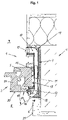
- figure 1 shows a section through the figure 4 at the level of the ventilation device 1, in particular above or below the central axis 3 of the ventilation device 1.
- the ventilation device 1 for supplying and/or discharging an air flow between a wall 4 and a fixed frame 5 of the window or a door 2 rests in a wall connection joint 6 on the fixed frame 5, extends from an outside 7 into an interior 8 of window or door 2, with one Basic housing 9, which is divided into at least three functional and shape-changed channel sections 10, 11, 12, which in turn form the entire air flow path.
- a first duct section 11 is designed as a flat duct, which rests with a flat side 13 on an end face 14 of the fixed frame 5, with the outer and inner duct sections 10, 12 on both sides of the first duct section 11 forming a flow opening 15, 16.
- the outer and inner channel section 10, 12 are arch-shaped with a flow opening 15, 16 opening out towards the window or the door 2 and a flat channel 11 with a radius 17, 18 facing the flat side 13 of the central channel section, at least the inner channel section 12 starting from the flat side 13 of the flat channel 11 at an obtuse angle 19 greater than 90° and thus moving away from an end face 20 of the window or the door 2 in the direction of the interior 8.
- the radius 17, 18 creates a soft, rounded transition of the duct routing from the flat duct 11 to the outer and inner duct section 10, 12.
- the incoming or outgoing flow speed of the air flow is only slightly affected by this.
- the channel sections 10, 11, 12 are preferably of the same cross section, for example as a rectangle.
- the advantageous effect can be achieved through the selected contour of the channel sections 10, 11, 12, which, due to the radius 18 with a transition into an angled area 19, allows the air flow to flow almost unchecked and silently through the guide channel 11 into the inner channel section 12 of the basic housing 9 up to a flow opening 16 forwards and after 1 or 2 on one of the windows or the door 2 directed inner side 21 of the wall 4 flows into the interior 8. Consequently, the radius 18 and the angled portion 19 proves to be correct 1 or 3 due to a weakened kinked edge of the guide channel in the inner channel section 12 for the air flow due to the low resistance for the air output as advantageous and has proven itself due to the low inherent noise of the air flow. Additionally, as in 1 and 3 shown, the radius 18 is adapted accordingly on both inner sides 13 of the inner channel section 12 .
- the flow opening 16 then has the greatest distance from the fixed frame 5 on the inside 21 of the wall 4 , starting from the window or the door 2 .
- the favorable course of the air flow also affects the in 3 visible sound insulation 23, which builds up smaller due to the already low inherent noise of the air flow, which causes a small size of the ventilation device 1 and good sound insulation 23 in the long term.
- the inside 21 of the wall 4 and thus the visible side at right angles to the window or the door 2 are in terms of optics and trend after 1 and 4 narrowly executed.
- the basic housing 9 with its duct sections 10, 11, 12 is arranged in such a way that, in a preferred embodiment, the flat end of the end face 14 of the fixed frame 5 is also Side 13 of the flat channel 11 or the central channel section ends and merges into the radius 18 of the inner channel section 12 , which continues to follow the course arranged in an arc and obtuse angle 19 and finally opens into the flow opening 16 .
- the direct transition of the flat duct 11 at the edge with the transition from the end face 14 to the end face 20 of the fixed frame 5 in the inner duct section 12 requires little installation space in the direction of the interior 8 despite advantageous properties.
- the window or door 2 remains behind 1 with the installation of the ventilation device 1 untouched in its original unprocessed state. There are no restrictions whatsoever in the switching sequence and in the freedom of movement of the window or the door 2.
- the leaf 24 can be adjusted without restriction in the specified opening directions. In 4 it is shown that the light opening, which is provided with a glazing 25, does not require any reduction by the ventilation device 1.
- the one-piece integral construction of the ventilation device 1 after 2 and the separate handling of the window or door 2 when installed in a building leaves the need for the use of a ventilation device 1 according to the subject of the invention free choice. Also, the number of ventilation device 1 and the position on the window or the Door 2, whether on the right or left, can be chosen freely.
- the ventilation device 1 is preferably laid in the wall 4 or in the reveal.
- the ventilation device 1 does not extend in the direction of the plane of the window or the door 2 adjacent to the fixed frame 5, but after 4 perpendicular to the window plane, which is imaged by the fixed frame 5 and the closed wing 24.
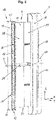
- the basic housing 9 is formed 2 in a longitudinal, transverse and depth direction L, Q, T, with a fastening section 27 or strip area extending approximately at the level of the central axis 3 of the longitudinal direction L over the length of the central first duct section 11 of the flat duct in the transverse direction Q divides the volume flow in regions within the flat channel 11 up to the respective channel sections 10, 12.
- the attachment section 27 can be used to mechanically attach the ventilation device 1 to the fixed frame 5 in the applied or attached area of the flat duct 11 .
- the window or door 2 can be anchored in the wall 4 or in the wall without a channel section 10, 11, 12 being interrupted by an anchoring screw of the window or door 2. Both variants are not shown in the drawing.
- the fastening section 27 dividing the longitudinal direction L acts as a stably fastened arrangement in the wall by anchoring the window or the door 2 4 or wall also against access from the outside and also provides resistance to a possible attempted break-in in the area where the ventilation device 1 is arranged.
- the size of the window or door 2 remains the same even when the ventilation device 1 is installed.
- the ventilation device 1 is after 1 arranged on one of the vertical fixed frames 5 on the side of the window or the door 2 and sunk into the wall 4 or in the masonry in the wall connection joint 6 of the reveal.
- the claimed space for the ventilation device 1 in the wall 4 extends to 2 not along the entire height of the window or door 2, but occupies only a small part in height and requires little depth in the reveal or the wall 4 even in the depth direction T due to the slender shape of the flat channel 11 of the ventilation device 1.
- the main extent of the ventilation device 1 is in the longitudinal direction L of the vertical direction, ie in a direction transverse to the direction of flow and the mounting surface of the fastening section 27 on the flat side, which is assigned to the fixed frame 5 .
- the extent in the transverse direction Q results from the thickness of the window or door 2 and the external and Inner channel sections 10, 12 to the outside 7 and the inside 8.
- the length of the transverse direction Q is less than the thickness of the wall 4 or wall ( 1 ).
- the fastening section 27 consists of a dimensionally stable material and/or is structured in a dimensionally stable manner, for example formed as a ribbed profile. In 1 it can be seen that the fastening section 27 does not protrude beyond the thickness of the flat channel 11 . Also not shown but conceivable are prefabricated holes for fastening screws for mounting the ventilation device 1 on the window or the door 2.
- FIG. 1 and 3 show the ventilation device 1 shown in cross section in the wall connection joint 6 or in the reveal with a two-part basic housing 9 through which air can flow.
- the split is located approximately in the middle of the transverse direction Q, with a first split housing half 28 and a second split housing half 29 together forming a slidably overlapping region 30 .
- the first flow opening 15 leading to the outside 7 associated with the first divided housing half 28 and the inwardly leading second flow opening 16, which opens into the interior 8 and is associated with the second divided housing half 29, can thus be telescoped in the transverse direction in the central channel section 11 of the flat channel move Q.
- a setting of varying thicknesses of the window or the door 2 is just as possible as an adjustment of different wall thicknesses of the wall or wall 4.
- the inner channel section 12 arranged towards the inner space 8 has 3 in a free operating field, an operating handle 31 for controlling a regulating device 32 of the air flow, which is preferably formed from a ventilation flap 33 and/or a slider and regulates the volume flow of the air flow.
- the ventilation flap 33 is preferably rotatably mounted in a duct section of the inner duct section 12 with a rectangular cross section on the inner wall 34 of the duct section, with the ventilation flap 33 being coupled to the actuating handle 31 with actuation, for example of a rotary knob, a rotary movement via a rotational axis 35 of a leg 36 of the ventilation flap 33 causes and comes to rest with a free end 37 of the leg 36 on the opposite inner wall 38 of the inner channel section 12 and closes the channel section and thus the air flow cross section.
- the leg 36 of the ventilation flap 33 - not shown - is approximately transverse to the flat duct wall and to the air flow.
- the flow cross-section can not only be opened and closed via the rotary knob 31, but also the air flow can be reduced and thus regulated. To achieve full efficiency and When the ventilation device 1 is fully utilized, the ventilation flap 33 remains as in 3 shown in a fully open airflow cross-section.
- the basic housing 9 contributes 3 due to an existing volume of space on the inner duct section 12 facing the outer shell of the interior 8 within the wall connection joint 6 the sound insulation or the sound insulation foam 23 and/or a sound insulation module is concealed.
- the insulating material thus lines at least the inner channel section 12 .
- the base housing 9 and the flow opening 16 on the inside 21 are at least partially lined with the insulating material. Due to the insulation, the ventilation device 1 has an acoustic—to avoid the transmission of structure-borne noise—, mechanically and thermally dampening effect.
- the applied insulation layer thus overlaps the interior 8 arranged inner channel section 12 and encloses the flow opening 15 opening into the interior 8 without encroaching on the inside 21 of the wall 4 or wall facing towards the window or the door 2 .
- the ventilation device 1 can be positioned on both sides of the window or the door 2 by simply turning it without structural changes. Using the same components of the ventilation device 1 results in the same arrangement of the components and the same installation situation and the same air flow conditions with the same sound insulation.
- the basic housing 9 of the ventilation device 1 consists of the channel sections 10, 11, 12, which are divided into three divided sections as a positive connection or also by one-piece mold sections. All functional components can be easily and quickly fixed in position and fastened.
- the integrated functional components in the basic housing 9 are connected to the covering weather protection 26 by a removable weather protection cover 39, the flow opening 15 to the outside 7 and by a cap 40 to the interior 8 2 and 3 completely concealed. Possible dirt, which can contribute to an impairment of the life of the ventilation device 1, are excluded by the sealing connection of the weather protection cover 39 and the cover cap 40.
- the functional components of the control device 32 or the channel sections 10, 11, 12 can also be simplified for possible maintenance by loosening a positive and/or non-positive connection of the weather protection cover 39 or the cover cap 40 and cleaning them if necessary.
- the weather protection cover 39 and the cap 40 can be used as Aperture, perforated plate, grid element or be designed as a slat or blind element.
- the ventilation device 1 is designed in particular to divert to the outside any type of weather-related moisture input, such as can occur in the case of driving rain, snowdrifts or shear water.
- the outer weather protection cover 39 or the outer channel section 10 has a special first flow opening 15 leading outwards in relation to the transition opening with a horizontally slanted course 41 .
- the upper horizontal area 43 is preferably the same as the lower area 42.
- Condensed water which can arise when air is discharged from an interior space to the outside, can also run off in a simple manner in the direction of the first outer air opening.
- plaster edges 44, 45 form the end of the weather protection cover 39 and the outer duct section 10.
Landscapes
- Engineering & Computer Science (AREA)
- Chemical & Material Sciences (AREA)
- Combustion & Propulsion (AREA)
- Mechanical Engineering (AREA)
- General Engineering & Computer Science (AREA)
- Civil Engineering (AREA)
- Structural Engineering (AREA)
- Specific Sealing Or Ventilating Devices For Doors And Windows (AREA)
Applications Claiming Priority (2)
| Application Number | Priority Date | Filing Date | Title |
|---|---|---|---|
| DE102018007864.8A DE102018007864A1 (de) | 2018-10-05 | 2018-10-05 | Lüftungsvorrichtung |
| PCT/EP2019/075781 WO2020069927A1 (de) | 2018-10-05 | 2019-09-25 | Lüftungsvorrichtung |
Publications (2)
| Publication Number | Publication Date |
|---|---|
| EP3861189A1 EP3861189A1 (de) | 2021-08-11 |
| EP3861189B1 true EP3861189B1 (de) | 2022-05-25 |
Family
ID=68109288
Family Applications (1)
| Application Number | Title | Priority Date | Filing Date |
|---|---|---|---|
| EP19780189.7A Active EP3861189B1 (de) | 2018-10-05 | 2019-09-25 | Lüftungsvorrichtung |
Country Status (5)
| Country | Link |
|---|---|
| EP (1) | EP3861189B1 (pl) |
| CN (1) | CN112739883B (pl) |
| DE (1) | DE102018007864A1 (pl) |
| PL (1) | PL3861189T3 (pl) |
| WO (1) | WO2020069927A1 (pl) |
Families Citing this family (2)
| Publication number | Priority date | Publication date | Assignee | Title |
|---|---|---|---|---|
| CN116312439B (zh) * | 2023-03-16 | 2025-06-17 | 哈尔滨理工大学 | 基于穿孔板的通风消声器 |
| CN120925746B (zh) * | 2025-10-14 | 2026-03-17 | 广州地铁设计研究院股份有限公司 | 高抗力变截面通道双向消波活门 |
Family Cites Families (6)
| Publication number | Priority date | Publication date | Assignee | Title |
|---|---|---|---|---|
| SK3182U (sk) * | 1999-02-03 | 2002-04-04 | Nemcek Milan Ing | Otvorová výplň s vetracím a zvukotlmiacim zariadením do priestorov |
| WO2004070155A1 (en) * | 2003-02-07 | 2004-08-19 | Jane Cynthia Margaret Harding | Window vent |
| DE102011055522B4 (de) * | 2011-11-18 | 2013-09-26 | Hautau Gmbh | Lüftungsgerät für den profilierten Blendrahmen eines Flügels (Fenster-Lüftungsgerät) und Luft-Austauschverfahren |
| AT512198B1 (de) * | 2011-11-18 | 2015-11-15 | Ifn Holding Ag | Fenster |
| DE102012104198A1 (de) * | 2012-05-14 | 2013-11-14 | Hautau Gmbh | Rahmenlüftungsgerät, Fensteranordnung und eingebautes Fenster mit Lüftungsgerät zum Lüften und zum Erhalt der regulären Verglasungsgröße und auch Rahmenmaße |
| PL230006B1 (pl) * | 2015-12-01 | 2018-09-28 | Cwikilewicz Marek Brevis Spolka Cywilna | Nawiewnik powietrza |
-
2018
- 2018-10-05 DE DE102018007864.8A patent/DE102018007864A1/de not_active Withdrawn
-
2019
- 2019-09-25 EP EP19780189.7A patent/EP3861189B1/de active Active
- 2019-09-25 WO PCT/EP2019/075781 patent/WO2020069927A1/de not_active Ceased
- 2019-09-25 PL PL19780189.7T patent/PL3861189T3/pl unknown
- 2019-09-25 CN CN201980061845.2A patent/CN112739883B/zh active Active
Also Published As
| Publication number | Publication date |
|---|---|
| CN112739883B (zh) | 2022-12-06 |
| CN112739883A (zh) | 2021-04-30 |
| WO2020069927A1 (de) | 2020-04-09 |
| DE102018007864A1 (de) | 2020-04-09 |
| EP3861189A1 (de) | 2021-08-11 |
| PL3861189T3 (pl) | 2022-08-16 |
Similar Documents
| Publication | Publication Date | Title |
|---|---|---|
| DE3200210A1 (de) | Lueftungseinrichtung | |
| EP2791452B1 (de) | Lüftungsvorrichtung für ein fenster oder eine tür | |
| EP3861189B1 (de) | Lüftungsvorrichtung | |
| WO2002036372A1 (de) | Luftleitdüse | |
| DE102008020941B4 (de) | Luftführungselement zum Zuführen und/oder Abführen von Luft | |
| EP2811102A1 (de) | Lüftermodul für Fenster und Fenster mit Lüftermodul hierfür | |
| DE19752019A1 (de) | Belüftungsvorrichtung und Belüftungssystem | |
| EP1837477B1 (de) | Fenster oder Tür mit Lüftung | |
| EP4124717A1 (de) | Lüftungsvorrichtung für ein fenster oder eine tür | |
| DE29823519U1 (de) | Öffnungsabdeckung zur gleichzeitigen Belüftung und Außenschalldämpfung | |
| DE102015014351A1 (de) | Belüftungselement für Fenster mit als Schikane wirkender Klappe | |
| EP3686505B1 (de) | Lufteinlass und anordnung zur führung von luft | |
| DE3785188T2 (de) | Lüftungsvorrichtung. | |
| EP3800317B1 (de) | Fenster mit einem lüftungskanal | |
| DE69406093T2 (de) | Selbstregelnder, rückstromsperrender Lufteinlass versehen mit einer akustischen Rolle, Installation versehen mit einem derartigen Lufteinlass | |
| DE3320993C2 (de) | Lüftungsvorrichtung zur Anordnung auf der Innenseite von Gebäudewänden | |
| EP1715133B1 (de) | Flügelüberschlagslüfter | |
| EP2886780B1 (de) | Falzlüfter | |
| EP3790749A1 (de) | Ausströmer für ein kraftfahrzeug | |
| DE3443501A1 (de) | Rahmenprofil fuer ein fenster | |
| WO1995009332A1 (de) | Zuluftgerät | |
| DE2226974A1 (de) | Ventilator | |
| DE19710779C2 (de) | Luftauslaß für Luftstrahlen mit großer Reichweite | |
| DE19912567A1 (de) | Luftleiteinrichtung für einen Luftdurchlaß | |
| DE102005018929B4 (de) | Flügelüberschlagslüfter |
Legal Events
| Date | Code | Title | Description |
|---|---|---|---|
| STAA | Information on the status of an ep patent application or granted ep patent |
Free format text: STATUS: UNKNOWN |
|
| STAA | Information on the status of an ep patent application or granted ep patent |
Free format text: STATUS: THE INTERNATIONAL PUBLICATION HAS BEEN MADE |
|
| PUAI | Public reference made under article 153(3) epc to a published international application that has entered the european phase |
Free format text: ORIGINAL CODE: 0009012 |
|
| STAA | Information on the status of an ep patent application or granted ep patent |
Free format text: STATUS: REQUEST FOR EXAMINATION WAS MADE |
|
| 17P | Request for examination filed |
Effective date: 20210331 |
|
| AK | Designated contracting states |
Kind code of ref document: A1 Designated state(s): AL AT BE BG CH CY CZ DE DK EE ES FI FR GB GR HR HU IE IS IT LI LT LU LV MC MK MT NL NO PL PT RO RS SE SI SK SM TR |
|
| DAV | Request for validation of the european patent (deleted) | ||
| DAX | Request for extension of the european patent (deleted) | ||
| GRAP | Despatch of communication of intention to grant a patent |
Free format text: ORIGINAL CODE: EPIDOSNIGR1 |
|
| STAA | Information on the status of an ep patent application or granted ep patent |
Free format text: STATUS: GRANT OF PATENT IS INTENDED |
|
| INTG | Intention to grant announced |
Effective date: 20220314 |
|
| GRAS | Grant fee paid |
Free format text: ORIGINAL CODE: EPIDOSNIGR3 |
|
| GRAA | (expected) grant |
Free format text: ORIGINAL CODE: 0009210 |
|
| STAA | Information on the status of an ep patent application or granted ep patent |
Free format text: STATUS: THE PATENT HAS BEEN GRANTED |
|
| AK | Designated contracting states |
Kind code of ref document: B1 Designated state(s): AL AT BE BG CH CY CZ DE DK EE ES FI FR GB GR HR HU IE IS IT LI LT LU LV MC MK MT NL NO PL PT RO RS SE SI SK SM TR |
|
| REG | Reference to a national code |
Ref country code: GB Ref legal event code: FG4D Free format text: NOT ENGLISH |
|
| REG | Reference to a national code |
Ref country code: CH Ref legal event code: EP |
|
| REG | Reference to a national code |
Ref country code: NL Ref legal event code: FP |
|
| REG | Reference to a national code |
Ref country code: AT Ref legal event code: REF Ref document number: 1494329 Country of ref document: AT Kind code of ref document: T Effective date: 20220615 Ref country code: DE Ref legal event code: R096 Ref document number: 502019004469 Country of ref document: DE |
|
| REG | Reference to a national code |
Ref country code: IE Ref legal event code: FG4D Free format text: LANGUAGE OF EP DOCUMENT: GERMAN |
|
| REG | Reference to a national code |
Ref country code: LT Ref legal event code: MG9D |
|
| PG25 | Lapsed in a contracting state [announced via postgrant information from national office to epo] |
Ref country code: SE Free format text: LAPSE BECAUSE OF FAILURE TO SUBMIT A TRANSLATION OF THE DESCRIPTION OR TO PAY THE FEE WITHIN THE PRESCRIBED TIME-LIMIT Effective date: 20220525 Ref country code: PT Free format text: LAPSE BECAUSE OF FAILURE TO SUBMIT A TRANSLATION OF THE DESCRIPTION OR TO PAY THE FEE WITHIN THE PRESCRIBED TIME-LIMIT Effective date: 20220926 Ref country code: NO Free format text: LAPSE BECAUSE OF FAILURE TO SUBMIT A TRANSLATION OF THE DESCRIPTION OR TO PAY THE FEE WITHIN THE PRESCRIBED TIME-LIMIT Effective date: 20220825 Ref country code: LT Free format text: LAPSE BECAUSE OF FAILURE TO SUBMIT A TRANSLATION OF THE DESCRIPTION OR TO PAY THE FEE WITHIN THE PRESCRIBED TIME-LIMIT Effective date: 20220525 Ref country code: HR Free format text: LAPSE BECAUSE OF FAILURE TO SUBMIT A TRANSLATION OF THE DESCRIPTION OR TO PAY THE FEE WITHIN THE PRESCRIBED TIME-LIMIT Effective date: 20220525 Ref country code: GR Free format text: LAPSE BECAUSE OF FAILURE TO SUBMIT A TRANSLATION OF THE DESCRIPTION OR TO PAY THE FEE WITHIN THE PRESCRIBED TIME-LIMIT Effective date: 20220826 Ref country code: FI Free format text: LAPSE BECAUSE OF FAILURE TO SUBMIT A TRANSLATION OF THE DESCRIPTION OR TO PAY THE FEE WITHIN THE PRESCRIBED TIME-LIMIT Effective date: 20220525 Ref country code: BG Free format text: LAPSE BECAUSE OF FAILURE TO SUBMIT A TRANSLATION OF THE DESCRIPTION OR TO PAY THE FEE WITHIN THE PRESCRIBED TIME-LIMIT Effective date: 20220825 |
|
| PG25 | Lapsed in a contracting state [announced via postgrant information from national office to epo] |
Ref country code: RS Free format text: LAPSE BECAUSE OF FAILURE TO SUBMIT A TRANSLATION OF THE DESCRIPTION OR TO PAY THE FEE WITHIN THE PRESCRIBED TIME-LIMIT Effective date: 20220525 Ref country code: LV Free format text: LAPSE BECAUSE OF FAILURE TO SUBMIT A TRANSLATION OF THE DESCRIPTION OR TO PAY THE FEE WITHIN THE PRESCRIBED TIME-LIMIT Effective date: 20220525 Ref country code: IS Free format text: LAPSE BECAUSE OF FAILURE TO SUBMIT A TRANSLATION OF THE DESCRIPTION OR TO PAY THE FEE WITHIN THE PRESCRIBED TIME-LIMIT Effective date: 20220925 |
|
| PG25 | Lapsed in a contracting state [announced via postgrant information from national office to epo] |
Ref country code: SM Free format text: LAPSE BECAUSE OF FAILURE TO SUBMIT A TRANSLATION OF THE DESCRIPTION OR TO PAY THE FEE WITHIN THE PRESCRIBED TIME-LIMIT Effective date: 20220525 Ref country code: SK Free format text: LAPSE BECAUSE OF FAILURE TO SUBMIT A TRANSLATION OF THE DESCRIPTION OR TO PAY THE FEE WITHIN THE PRESCRIBED TIME-LIMIT Effective date: 20220525 Ref country code: RO Free format text: LAPSE BECAUSE OF FAILURE TO SUBMIT A TRANSLATION OF THE DESCRIPTION OR TO PAY THE FEE WITHIN THE PRESCRIBED TIME-LIMIT Effective date: 20220525 Ref country code: ES Free format text: LAPSE BECAUSE OF FAILURE TO SUBMIT A TRANSLATION OF THE DESCRIPTION OR TO PAY THE FEE WITHIN THE PRESCRIBED TIME-LIMIT Effective date: 20220525 Ref country code: EE Free format text: LAPSE BECAUSE OF FAILURE TO SUBMIT A TRANSLATION OF THE DESCRIPTION OR TO PAY THE FEE WITHIN THE PRESCRIBED TIME-LIMIT Effective date: 20220525 Ref country code: DK Free format text: LAPSE BECAUSE OF FAILURE TO SUBMIT A TRANSLATION OF THE DESCRIPTION OR TO PAY THE FEE WITHIN THE PRESCRIBED TIME-LIMIT Effective date: 20220525 Ref country code: CZ Free format text: LAPSE BECAUSE OF FAILURE TO SUBMIT A TRANSLATION OF THE DESCRIPTION OR TO PAY THE FEE WITHIN THE PRESCRIBED TIME-LIMIT Effective date: 20220525 |
|
| REG | Reference to a national code |
Ref country code: DE Ref legal event code: R097 Ref document number: 502019004469 Country of ref document: DE |
|
| PG25 | Lapsed in a contracting state [announced via postgrant information from national office to epo] |
Ref country code: AL Free format text: LAPSE BECAUSE OF FAILURE TO SUBMIT A TRANSLATION OF THE DESCRIPTION OR TO PAY THE FEE WITHIN THE PRESCRIBED TIME-LIMIT Effective date: 20220525 |
|
| PLBE | No opposition filed within time limit |
Free format text: ORIGINAL CODE: 0009261 |
|
| STAA | Information on the status of an ep patent application or granted ep patent |
Free format text: STATUS: NO OPPOSITION FILED WITHIN TIME LIMIT |
|
| PG25 | Lapsed in a contracting state [announced via postgrant information from national office to epo] |
Ref country code: MC Free format text: LAPSE BECAUSE OF FAILURE TO SUBMIT A TRANSLATION OF THE DESCRIPTION OR TO PAY THE FEE WITHIN THE PRESCRIBED TIME-LIMIT Effective date: 20220525 |
|
| 26N | No opposition filed |
Effective date: 20230228 |
|
| PG25 | Lapsed in a contracting state [announced via postgrant information from national office to epo] |
Ref country code: LU Free format text: LAPSE BECAUSE OF NON-PAYMENT OF DUE FEES Effective date: 20220925 |
|
| PG25 | Lapsed in a contracting state [announced via postgrant information from national office to epo] |
Ref country code: IE Free format text: LAPSE BECAUSE OF NON-PAYMENT OF DUE FEES Effective date: 20220925 |
|
| PG25 | Lapsed in a contracting state [announced via postgrant information from national office to epo] |
Ref country code: IT Free format text: LAPSE BECAUSE OF FAILURE TO SUBMIT A TRANSLATION OF THE DESCRIPTION OR TO PAY THE FEE WITHIN THE PRESCRIBED TIME-LIMIT Effective date: 20220525 |
|
| PG25 | Lapsed in a contracting state [announced via postgrant information from national office to epo] |
Ref country code: CY Free format text: LAPSE BECAUSE OF FAILURE TO SUBMIT A TRANSLATION OF THE DESCRIPTION OR TO PAY THE FEE WITHIN THE PRESCRIBED TIME-LIMIT Effective date: 20220525 |
|
| PG25 | Lapsed in a contracting state [announced via postgrant information from national office to epo] |
Ref country code: MK Free format text: LAPSE BECAUSE OF FAILURE TO SUBMIT A TRANSLATION OF THE DESCRIPTION OR TO PAY THE FEE WITHIN THE PRESCRIBED TIME-LIMIT Effective date: 20220525 Ref country code: HU Free format text: LAPSE BECAUSE OF FAILURE TO SUBMIT A TRANSLATION OF THE DESCRIPTION OR TO PAY THE FEE WITHIN THE PRESCRIBED TIME-LIMIT; INVALID AB INITIO Effective date: 20190925 |
|
| PG25 | Lapsed in a contracting state [announced via postgrant information from national office to epo] |
Ref country code: MT Free format text: LAPSE BECAUSE OF FAILURE TO SUBMIT A TRANSLATION OF THE DESCRIPTION OR TO PAY THE FEE WITHIN THE PRESCRIBED TIME-LIMIT Effective date: 20220525 |
|
| PG25 | Lapsed in a contracting state [announced via postgrant information from national office to epo] |
Ref country code: BG Free format text: LAPSE BECAUSE OF FAILURE TO SUBMIT A TRANSLATION OF THE DESCRIPTION OR TO PAY THE FEE WITHIN THE PRESCRIBED TIME-LIMIT Effective date: 20220525 |
|
| PG25 | Lapsed in a contracting state [announced via postgrant information from national office to epo] |
Ref country code: BG Free format text: LAPSE BECAUSE OF FAILURE TO SUBMIT A TRANSLATION OF THE DESCRIPTION OR TO PAY THE FEE WITHIN THE PRESCRIBED TIME-LIMIT Effective date: 20220525 |
|
| REG | Reference to a national code |
Ref country code: CH Ref legal event code: U11 Free format text: ST27 STATUS EVENT CODE: U-0-0-U10-U11 (AS PROVIDED BY THE NATIONAL OFFICE) Effective date: 20251001 |
|
| PGFP | Annual fee paid to national office [announced via postgrant information from national office to epo] |
Ref country code: PL Payment date: 20250825 Year of fee payment: 7 Ref country code: NL Payment date: 20250927 Year of fee payment: 7 |
|
| PGFP | Annual fee paid to national office [announced via postgrant information from national office to epo] |
Ref country code: BE Payment date: 20250925 Year of fee payment: 7 Ref country code: GB Payment date: 20250927 Year of fee payment: 7 |
|
| PGFP | Annual fee paid to national office [announced via postgrant information from national office to epo] |
Ref country code: FR Payment date: 20250926 Year of fee payment: 7 Ref country code: AT Payment date: 20250923 Year of fee payment: 7 |
|
| PG25 | Lapsed in a contracting state [announced via postgrant information from national office to epo] |
Ref country code: TR Free format text: LAPSE BECAUSE OF FAILURE TO SUBMIT A TRANSLATION OF THE DESCRIPTION OR TO PAY THE FEE WITHIN THE PRESCRIBED TIME-LIMIT Effective date: 20220525 |
|
| PGFP | Annual fee paid to national office [announced via postgrant information from national office to epo] |
Ref country code: DE Payment date: 20251002 Year of fee payment: 7 |
|
| PGFP | Annual fee paid to national office [announced via postgrant information from national office to epo] |
Ref country code: CH Payment date: 20251001 Year of fee payment: 7 |
|
| PG25 | Lapsed in a contracting state [announced via postgrant information from national office to epo] |
Ref country code: SI Free format text: LAPSE BECAUSE OF FAILURE TO SUBMIT A TRANSLATION OF THE DESCRIPTION OR TO PAY THE FEE WITHIN THE PRESCRIBED TIME-LIMIT Effective date: 20220525 |