EP3861188B1 - Elektrifizierte leistenanordnung - Google Patents
Elektrifizierte leistenanordnung Download PDFInfo
- Publication number
- EP3861188B1 EP3861188B1 EP20803084.1A EP20803084A EP3861188B1 EP 3861188 B1 EP3861188 B1 EP 3861188B1 EP 20803084 A EP20803084 A EP 20803084A EP 3861188 B1 EP3861188 B1 EP 3861188B1
- Authority
- EP
- European Patent Office
- Prior art keywords
- conductor
- plastic frame
- frame element
- contact
- electrical
- Prior art date
- Legal status (The legal status is an assumption and is not a legal conclusion. Google has not performed a legal analysis and makes no representation as to the accuracy of the status listed.)
- Active
Links
Images



Classifications
-
- E—FIXED CONSTRUCTIONS
- E06—DOORS, WINDOWS, SHUTTERS, OR ROLLER BLINDS IN GENERAL; LADDERS
- E06B—FIXED OR MOVABLE CLOSURES FOR OPENINGS IN BUILDINGS, VEHICLES, FENCES OR LIKE ENCLOSURES IN GENERAL, e.g. DOORS, WINDOWS, BLINDS, GATES
- E06B3/00—Window sashes, door leaves, or like elements for closing wall or like openings; Layout of fixed or moving closures, e.g. windows in wall or like openings; Features of rigidly-mounted outer frames relating to the mounting of wing frames
- E06B3/04—Wing frames not characterised by the manner of movement
- E06B3/06—Single frames
- E06B3/08—Constructions depending on the use of specified materials
- E06B3/20—Constructions depending on the use of specified materials of plastics
-
- H—ELECTRICITY
- H01—ELECTRIC ELEMENTS
- H01R—ELECTRICALLY-CONDUCTIVE CONNECTIONS; STRUCTURAL ASSOCIATIONS OF A PLURALITY OF MUTUALLY-INSULATED ELECTRICAL CONNECTING ELEMENTS; COUPLING DEVICES; CURRENT COLLECTORS
- H01R43/00—Apparatus or processes specially adapted for manufacturing, assembling, maintaining, or repairing of line connectors or current collectors or for joining electric conductors
- H01R43/20—Apparatus or processes specially adapted for manufacturing, assembling, maintaining, or repairing of line connectors or current collectors or for joining electric conductors for assembling or disassembling contact members with insulating base, case or sleeve
- H01R43/24—Assembling by moulding on contact members
-
- E—FIXED CONSTRUCTIONS
- E06—DOORS, WINDOWS, SHUTTERS, OR ROLLER BLINDS IN GENERAL; LADDERS
- E06B—FIXED OR MOVABLE CLOSURES FOR OPENINGS IN BUILDINGS, VEHICLES, FENCES OR LIKE ENCLOSURES IN GENERAL, e.g. DOORS, WINDOWS, BLINDS, GATES
- E06B3/00—Window sashes, door leaves, or like elements for closing wall or like openings; Layout of fixed or moving closures, e.g. windows in wall or like openings; Features of rigidly-mounted outer frames relating to the mounting of wing frames
- E06B3/54—Fixing of glass panes or like plates
- E06B3/5454—Fixing of glass panes or like plates inside U-shaped section members
-
- E—FIXED CONSTRUCTIONS
- E06—DOORS, WINDOWS, SHUTTERS, OR ROLLER BLINDS IN GENERAL; LADDERS
- E06B—FIXED OR MOVABLE CLOSURES FOR OPENINGS IN BUILDINGS, VEHICLES, FENCES OR LIKE ENCLOSURES IN GENERAL, e.g. DOORS, WINDOWS, BLINDS, GATES
- E06B3/00—Window sashes, door leaves, or like elements for closing wall or like openings; Layout of fixed or moving closures, e.g. windows in wall or like openings; Features of rigidly-mounted outer frames relating to the mounting of wing frames
- E06B3/66—Units comprising two or more parallel glass or like panes permanently secured together
- E06B3/67—Units comprising two or more parallel glass or like panes permanently secured together characterised by additional arrangements or devices for heat or sound insulation or for controlled passage of light
- E06B3/6715—Units comprising two or more parallel glass or like panes permanently secured together characterised by additional arrangements or devices for heat or sound insulation or for controlled passage of light specially adapted for increased thermal insulation or for controlled passage of light
- E06B3/6722—Units comprising two or more parallel glass or like panes permanently secured together characterised by additional arrangements or devices for heat or sound insulation or for controlled passage of light specially adapted for increased thermal insulation or for controlled passage of light with adjustable passage of light
-
- H—ELECTRICITY
- H01—ELECTRIC ELEMENTS
- H01R—ELECTRICALLY-CONDUCTIVE CONNECTIONS; STRUCTURAL ASSOCIATIONS OF A PLURALITY OF MUTUALLY-INSULATED ELECTRICAL CONNECTING ELEMENTS; COUPLING DEVICES; CURRENT COLLECTORS
- H01R2201/00—Connectors or connections adapted for particular applications
- H01R2201/26—Connectors or connections adapted for particular applications for vehicles
Definitions
- the present invention relates to a connection arrangement and a strip arrangement for electrically connecting an electrified surface element formed with an electrical peripheral contact to an electrical device.
- intelligent glass can be understood as glass panes that can change their appearance through physical influences such as UV radiation, heat or electricity, for example also dimmable glass.
- a special film is laminated between two panes of glass and contacted via electrical contacts that lead out of the glass. Contact to the power source is made by soldering or by a plug-in connection with cables. The cables must be led away from the surface element and laid in a protected manner and connected to a supply/signal source, usually this is done freely wired.
- the invention also relates to less complex applications such as in document DE 103 60 255 A1 shown where the same problem occurs in the automotive sector with a heated window.
- the DE 20 2015 008 064 U1 discloses structural components of an awning arranged transversely to one another.
- An electrical supply line can be laid through one of the structural components to supply an element that is independent of the structural components.
- the particular disadvantage here is that the structural components are contacted only at the respective end regions of the structural components.
- the WO 2012/148103 A1 reveals a window with a color-sensitive solar cell and an electrochromic window.
- the disadvantage here is that only the use of solar cell modules in windows is shown and other possible applications where a view through the window is desired are not taken into account. Due to the orthogonal position of the solar cell to the frame element, there is increased assembly effort. In addition, the overall structure, on the one hand the creation of the solar cell module and on the other hand the additional cabling of the individual modules in a frame, is complex to implement.
- EP 3 219 529 A1 describes a plastic profile with a U-shaped cross section and with an integrated metallic reinforcing element.
- a specialist is usually required for the power supply and the contacting of the surface element.
- Cable routing must be provided in the adjacent components or at least enough mounting space, which influences the design of these components.
- Loose cables make it difficult to assemble individual surface elements, e.g segmented large area, comprising several smaller area elements. Depending on the installation, the cables and contacts are visible, which is of course less visually appealing and more likely to indicate an unfinished solution. It is therefore desirable to eliminate these disadvantages and provide a more suitable solution.
- connection arrangement according to claim 1 and a strip arrangement according to claim 10 are proposed.
- An electrified pane made of intelligent glass or electrochromic glass can be used as a surface element.
- the invention covers both single glazing and multiple glazing.
- the invention is based on the idea of reducing the assembly effort for electrified surface elements by using the highest possible proportion of identical parts, which cost-effectively reduce and simplify the wiring and contacting effort for electrified surface elements.
- the solution according to the invention eliminates the disadvantages mentioned and provides a high level of flexibility, because due to the implementation according to the invention, the strip arrangement - regardless of the position of the peripheral contact - can be used on surface elements with peripheral contacts in a wide variety of positions. A large number of surface elements from different manufacturers can be provided with the same strip arrangement.
- the strip arrangement according to the invention can easily be produced as a strand by extrusion. It is also conceivable to produce a standard length, which the customer can cut and edit themselves (e.g. miter cutting to encompass corners of surface elements). Alternatively, specially shaped connecting elements with electrical conductors can be used to connect strips.
- the conductor is preferably realized using a metal (e.g. stranded wire, wire, etc.).
- a metal e.g. stranded wire, wire, etc.
- the advantage of this variant is that the electrical losses in the conductor are minimal and the conductor can be easily introduced into the plastic frame element during, for example, extrusion of the plastic frame element. This arrangement is inexpensive and can be produced in large quantities with minimal cycle times.
- the conductor can be realized exclusively by means of an electrically conductive second plastic, the electrical resistance of which, due to the presence of electrically conductive plastic additives (e.g. soot, metal particles and the like), is many times lower than the conductivity of a first plastic, by means of which the Plastic frame element can be realized.
- electrically conductive plastic additives e.g. soot, metal particles and the like
- the conductor can also be realized using a combination of the two previously mentioned variants, namely an electrically conductive second plastic and a metal.
- a metallic conductor represents the conductor core, which can be melted or covered by the second plastic at least in sections and at least on the surface element side.
- the production can be carried out by co-extrusion of the first and second plastic with simultaneous introduction of the metallic conductor. This solution is just as advantageous as the two solutions mentioned above.
- first contact elements in particular spring contact elements
- the conductor and/or the contact elements preferably being formed in one piece.
- Conductors and contact elements can therefore be produced easily and inexpensively, for example by means of a metal strip, which is processed according to the invention in such a way that a continuous conductor with contact springs arranged along the conductor results.
- a freely positionable coupling element can be provided along the conductor in order to make the strip configurable.
- Several coupling elements can be provided in conjunction with several mutually insulated conductors to realize several connections that are electrically insulated from one another in order to also cover more complex fields of application.
- electrified surface segments that can be controlled in segments within a single surface element or a wall comprising several surface elements which are connected to one another by means of segmented and/or continuous strip arrangements should be mentioned here.
- the coupling element comprises second contact elements for contacting the conductor and/or the peripheral contact, so that contacting the coupling element with the conductor and/or contacting the coupling element with the peripheral contact can be achieved during the connection production.
- This has the advantage that all electrical components initially remain electrically isolated from one another until the strip arrangement is attached to the surface element.
- This Contact elements are preferably implemented as a piercing contact and/or as a cutting contact. Both variants are suitable for puncturing the conductive and/or non-conductive plastic jacket of the conductor at specific points only when the plastic frame element is arranged on the surface element or for cutting it open locally and transversely to the conductor extension, so that the conductor is only contacted at the desired positions for establishing a connection.
- the circumferential contact particularly in the case of two or more conductors, can be insulated from one or more of the conductors in defined areas. As a result, only selected conductors can be selectively contacted in an electrically conductive manner in a circumscribed area.
- Connecting elements are preferably provided for connecting individual plastic frame elements with electrical conductors.
- the connecting elements also have one or more electrical conductors at the level of the electrical conductors. Depending on the shape of the connecting element, these serve to connect two strips according to the invention in a longitudinal direction or to connect two strips at a 90 ° angle to one another, but other angles are also possible and within the scope of the invention.
- the electrical supply line for powering the strip arrangement can also be located in a connecting element.
- FIG. 1a to 4 show exemplary and preferred variants of the strip arrangement 100 according to the invention in a sectional view.
- the assemblies shown here each include a surface element 105 in the form of an electrified pane (eg electrochromic glass), which is designed with an external flexible ribbon conductor or an electrically conductive film as a peripheral contact 106.
- An electrical device is required (not shown) to control (e.g. data, signals) or to supply energy (e.g. electrical current and/or electrical voltage) to the electrochromic layer.
- the connection between the peripheral contact 106 of the surface element 105 and the device can be advantageously realized.
- a plastic frame element 101 which is preferably U-shaped in cross section, each with two electrical conductors 102 and a surface element 105 with peripheral contact 106 are shown roughly schematically.
- the plastic frame element 101 runs on both sides along the edge of the surface element 105.
- other cross sections are also conceivable, for example an L-shaped cross section.
- at least one contact surface must be provided for arranging the plastic frame element 101 on the edge of the surface element.
- Figure 1a shows, for example, a first strip arrangement 100, in which the opposing conductors 102 are provided on the surface element side and along the plastic frame element 101, so that the conductors 102 automatically and directly come into contact with the peripheral contacts 106 during the arrangement of the plastic frame element 101 on the peripheral section 107 and an electrical Connection between the electrical conductors 102 and the peripheral contacts 106 is established.
- Figure 1a only a left-side contact to the first conductor 102 is indicated, while the right-side conductor 102 is intended for a second peripheral contact 106 (not shown) provided elsewhere.
- Both conductors 102 are enclosed by a conductive plastic 109, which directly adjoins the plastic of the plastic frame element 101 or, for example, is preferably connected to it in a materially bonded manner by means of co-extrusion.
- the plastic frame element 101 can be designed to be resilient, so that the surface element 105 is clamped with its peripheral contacts 106 between the conductors 102 of both frame element legs (eg with a suitably designed U-shape).
- secure contact can also be achieved by gluing the plastic frame element 101 on (eg with L-shape), so that the circumferential contacts 106 are clamped between the conductors 102 and the surface element 105.
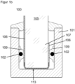
- Figure 1b shows a strip arrangement 100 with a surface element 105 in the form of a simple glass pane and a peripheral contact 106 in the form of a conductive film.
- the peripheral contact 106 comprises an electrically insulating layer 113 between the contact points with the electrical conductors 102.
- the plastic frame element 101 has electrical conductors 102 on both sides, which are surrounded by an electrically conductive plastic 109. Incidentally, this previously applies to Figure 1a Said.
- Figure 2a shows, for example, a second strip arrangement 100, in which a plurality of contact elements 108 are preferably provided continuously along two opposing conductors 102, the conductors 102 and the contact elements 108 preferably each being formed in one piece.
- This is preferably an elastic material for the realization of spring contact elements, which automatically rest resiliently on the circumferential contacts 106 during the arrangement of the plastic frame element 101 on the circumferential section 107 and thus establish an electrical connection between the electrical conductors 102 and the circumferential contacts 106.
- Figure 2a only a left-side contact to the first conductor 102 is indicated, while the right-side conductor 102 is intended for a second peripheral contact 106 (not shown) provided elsewhere.
- Both conductors 102 are preferably enclosed at least in sections by the material of the plastic frame element 101, whereas the contact elements 108 protrude from the legs of the plastic frame element 101 and, as shown, are shaped in such a way that they rest resiliently on the peripheral contact 106.
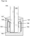
- the Figure 2b shows several conductors 102 arranged one above the other, with the conductors 102 located at the same height lying opposite each other in pairs.
- the area of the peripheral contact 106 which is not intended to come into contact with the conductor 102, is provided with an electrically insulating layer 113.
- a left-side contact to the first conductor 102 is indicated, while the right-side conductor 102 is intended for a second peripheral contact 106 (not shown) provided elsewhere.
- the conductors 102 are preferably at least partially enclosed by the material of the plastic frame element 101, whereas the contact elements 108 protrude from the legs of the plastic frame element 101 and are shaped in such a way that they rest resiliently on the peripheral contact 106.
- Figure 3 shows, for example, a third strip arrangement 100, in which a freely positionable and electrically conductive coupling element 104 is provided along two opposing conductors 102 for indirectly contacting the circumferential contacts 106. This can automatically apply to the peripheral contacts 106 and the conductors 102 during the arrangement of the plastic frame element 101 on the peripheral section 107 and thus establish an electrical connection between the conductors 102 and the peripheral contacts 106.
- Figure 3 only a left-side contact to the first conductor 102 is indicated, while the right-side conductor 102 is intended for a second peripheral contact 106 (not shown) provided elsewhere.
- a cutting contact 103 can be provided in order to contact the plastic jacket 112 of the conductors 102 and/or the conductors 102 at least in sections or to penetrate into the electrical conductors 102 in order to establish the electrical contact.
- a large number of mutually insulated conductors 102 could be contacted independently of one another, for example by means of different cutting depths.
- the plastic frame element 101 can be designed to be stiffer overall along the circumference than on the surface element-side groove leg area 111. This can be achieved by co-extrusion of similar materials with different Shore hardnesses or by co-extrusion of different materials with the same Shore hardness or from a combination of different types of materials, each with different Shore hardness.
- a thermoplastic could be provided and on the groove leg area 111, for example, an elastomer 110 could be provided, for example a thermoplastic elastomer (TPE).
- TPE thermoplastic elastomer
- the elastomer 110 could simultaneously function as a conductor jacket 112 in the area surrounding the conductor 102 and be provided with electrically conductive additives at least in sections.
- Figure 4 shows, for example, a fourth strip arrangement 100, with an electrically conductive coupling element 104 that can be freely positioned along the conductors 102 and is provided along two conductors 102 running parallel and next to one another for indirect contacting of the peripheral contacts 106. During the arrangement of the plastic frame element 101 on the peripheral section 107, this can automatically rest on or penetrate the peripheral contacts 106 and the conductors 102 and thus establish an electrical connection between the conductors 102 and the peripheral contacts 106. In Figure 4 only a left-side contact to the first conductor 102 is indicated, while the right-side conductor 102 is intended for a second peripheral contact 106 (not shown) provided elsewhere.
- a piercing contact 103 can be provided in order to pierce the plastic jacket 112 of the conductors 102 and at least partially penetrate into the electrical conductors 102 and thus establish the electrical contact.
- a large number of mutually insulated conductors 102 could be contacted independently of one another, for example by means of different piercing depths.
- the U-shaped plastic frame element 101 can include a further groove at the bottom of the groove, within which the two conductors 102 run isolated from one another. The groove can be filled with another plastic 110.
- This plastic 110 can be realized by co-extrusion of similar materials with different Shore hardnesses or by co-extrusion of different materials of the same Shore hardness or can be realized from a combination of different materials with different Shore hardnesses.
- This plastic 110 could simultaneously function as a conductor jacket in the area surrounding the conductor 102 and be provided with electrically conductive additives at least in sections.
- a TPE material could be designed to be partially or completely conductive as a conductor jacket 112, so that the electrical contact can be established without the contact elements 103 completely penetrating the conductors 102.
- the plastic frame element 101 can comprise a sealing plastic for sealing purposes, which can be provided on both sides along the upper groove edge of the plastic frame element 101, for example by means of co-extrusion. This protects the contact or arrangement from adverse environmental conditions after the plastic frame element 101 has been mounted on the surface element 105.
- FIGS. 5a and 5b show connecting elements 114 for connecting two plastic strip elements 101 according to the invention with electrical conductors 102 located therein.
- the Figure 5a shows a connection in which two plastic strip elements 101 with electrical conductors 102 located therein are connected to one another at a 90 ° angle to one another by means of a connecting element 114. Electrical conductors 102 are located in the connecting element 114, so that the electrical connection between the plastic strip elements 101 is ensured.
- the Figure 5b shows a longitudinal connection of two plastic strip elements 101 with electrical conductors 102 located therein. This connection is made by two connecting elements 114 with electrical conductors 102 located therein. The two connecting elements 114 in turn are then connected to one another in an electrically conductive manner. Alternatively, the two connecting elements 114 shown for the longitudinal connection of two plastic strip elements 101 can also be combined into an assembly 115 or made in one piece.
Landscapes
- Engineering & Computer Science (AREA)
- Civil Engineering (AREA)
- Structural Engineering (AREA)
- Manufacturing & Machinery (AREA)
- Push-Button Switches (AREA)
- Resistance Heating (AREA)
- Injection Moulding Of Plastics Or The Like (AREA)
- Joining Of Glass To Other Materials (AREA)
- Coupling Device And Connection With Printed Circuit (AREA)
Description
- Die vorliegende Erfindung betrifft eine Verbindungsanordnung und eine Leistenanordnung zur elektrischen Verbindung eines mit einem elektrischen Umfangskontakt ausgebildeten elektrifizierten Flächenelementes mit einer elektrischen Einrichtung.
- Heute existiert keine einheitliche und verbreitete Lösung zum Kontaktieren von intelligentem Glas bzw. funktionalen Flächenelementen bzw. elektrifizierten Flächenelementen. Unter z.B. intelligentem Glas können Glasscheiben verstanden werden, die durch physikalische Einflussgrößen wie UV-Strahlung, Wärme oder Strom ihr Erscheinungsbild verändern können, bspw. auch dimmbares Glas. Hierbei wird eine spezielle Folie zwischen zwei Glasscheiben laminiert und über elektrische Kontakte, die aus dem Glas herausführen, kontaktiert. Der Kontakt zur Stromquelle erfolgt durch Lötung oder durch eine Steckverbindung mit Kabeln. Die Kabel müssen vom Flächenelement weggeführt werden und geschützt verlegt werden sowie mit einer Versorgung/Signalquelle verbunden werden, in der Regel erfolgt dies frei verdrahtet. Generell bezieht sich die Erfindung aber auch auf weniger komplexe Anwendungen wie in Dokument
DE 103 60 255 A1 gezeigt, wo dieselbe Problematik im KFZ-Bereich bei einer beheizbaren Scheibe auftritt. - Die
DE 20 2015 008 064 U1 offenbart quer zueinander angeordnete Strukturbauteile einer Markise. Durch eines der Strukturbauteile kann eine elektrische Versorgungsleitung zur Versorgung eines von den strukturbauteilen unabhängigen Elements gelegt werden. Nachteilig ist hier insbesondere, dass eine Kontaktierung der Strukturbauteile nur an den jeweiligen Endbereichen der Strukturbauteile erfolgt. - Die
WO 2012/148103 A1 offenbart ein Fenster mit einer farbsensitiven Solarzelle und ein elektrochromes Fenster. Nachteilig ist hier, dass nur die Verwendung von Solarzell-Modulen in Fenstern gezeigt wird und andere Anwendungsmöglichkeiten, bei denen eine Durchsicht durch das Fenster gewünscht ist, unberücksichtigt bleiben. Auf Grund der orthogonalen Stellung der Solarzelle zum Rahmenelement liegt ein erhöhter Montageaufwand vor. Zudem ist der Gesamtaufbau, einerseits die Erstellung des Solarzell-Moduls und anderseits die zusätzliche Verkabelung der einzelnen Module in einem Rahmen, aufwendig zu realisieren. -
EP 3 219 529 A1 beschreibt ein Kunststoffprofil mit einem U-förmigen Querschnitt und mit einem integrierten metallischen Verstärkungselement. - Für die Stromversorgung und die Kontaktierung des Flächenelementes wird in der Regel ein Fachmann benötigt. Es muss eine Kabelführung in den angrenzenden Bauteilen vorgesehen werden oder zumindest genügend Montageraum, was die Konstruktion dieser Bauteile beeinflusst. Lose Kabel erschweren die Montage einzelner Flächenelemente bei einer z.B. segmentierten Großfläche, umfassend mehrere kleinere Flächenelemente. Je nach Montage sind die Kabel und Kontakte sichtbar, was natürlich optisch weniger ansprechend ist und eher auf eine unfertige Lösung hindeutet. Es ist daher wünschenswert, diese Nachteile zu beseitigen und eine geeignetere Lösung bereitzustellen.
- Erfindungsgemäß wird eine Verbindungsanordnung gemäß Anspruch 1 und eine Leistenanordnung gemäß Anspruch 10 vorgeschlagen.
- Als Flächenelement kommt eine elektrifizierte Scheibe etwa aus intelligentem Glas oder elektrochromem Glas in Frage. Von der Erfindung sind sowohl Einfachverglasungen als auch Mehrfachverglasungen umfasst.
- Die Erfindung beruht auf der Idee, den Montageaufwand bei elektrifizierten Flächenelementen mittels eines möglichst hohen Anteils von Gleichteilen zu reduzieren, welche den Verdrahtungs- und Kontaktierungsaufwand bei elektrifizierten Flächenelementen kostengünstig reduzieren und vereinfachen.
- Die erfindungsgemäße Lösung beseitigt die genannten Nachteile und liefert eine hohe Flexibilität, denn aufgrund der erfindungsgemäßen Realisierung ist die Leistenanordnung - unabhängig von der Lage des Umfangskontaktes - an Flächenelementen mit Umfangskontakten an unterschiedlichsten Positionen verwendbar. Eine Vielzahl von Flächenelementen verschiedenster Hersteller können mit ein und derselben Leistenanordnung versehen werden. Die erfindungsgemäße Leistenanordnung kann leicht als Strang mittels Extrusion hergestellt werden. Auch die Herstellung einer Standardlänge ist denkbar, welche der Kunde selbst ablängen und bearbeiten kann (z.B. auf Gehrung schneiden zum Umfassen von Flächenelementecken). Alternativ können speziell geformte Verbindungselemente mit elektrischen Leitern für die Verbindung von Leisten verwendet werden.
- Vorteilhafte Ausgestaltungen sind Gegenstand der Unteransprüche sowie der nachfolgenden Beschreibung.
- Bevorzugt ist der Leiter mittels eines Metalls (z.B. Litze, Draht etc.) realisiert. Der Vorteil dieser Variante besteht darin, dass die elektrischen Verluste im Leiter minimal sind und der Leiter während beispielsweise einer Extrusion des Kunststoffrahmenelementes in das Kunststoffrahmenelement leicht einbringbar ist. Diese Anordnung ist preiswert und in großen Stückzahlen bei minimalen Taktzeiten herstellbar.
- Alternativ kann der Leiter ausschließlich mittels eines elektrisch leitfähigen zweiten Kunststoffes realisiert sein, dessen elektrischer Widerstand aufgrund des Vorhandenseins von elektrisch leitfähigen Kunststoff-Zusatzstoffen (z.B. Ruß, Metallpartikel und dergleichen) um ein Vielfaches geringer ist, als die Leitfähigkeit eines ersten Kunststoffes, mittels dessen das Kunststoffrahmenelement realisiert sein kann. Der Vorteil dieser Variante besteht darin, dass sowohl der Leiter als auch das Rahmenelement mittels Co-Extrusion des ersten und zweiten Kunststoffes preiswert und in großen Stückzahlen bei ebenso geringen Taktzeiten herstellbar ist.
- Weiter alternativ kann der Leiter auch mittels einer Kombination aus den beiden zuvor genannten Varianten realisiert sein, nämlich aus einem elektrisch leitfähigen zweiten Kunststoff und einem Metall. In diesem Falle stellt ein metallischer Leiter den Leiterkern dar, welcher zumindest abschnittsweise und zumindest flächenelementseitig von dem zweiten Kunststoff umschmolzen oder abgedeckt sein kann. Die Herstellung kann mittels Co-Extrusion des ersten und zweiten Kunststoffes bei gleichzeitiger Einbringung des metallischen Leiters erfolgen. Diese Lösung ist ebenso vorteilhaft wie die zuvor genannten beiden Lösungen.
- Bevorzugt sind zur Herstellung der Verbindung eine Vielzahl von ersten Kontaktelementen, insbesondere von Federkontaktelementen, entlang des Leiters vorgesehen, wobei der Leiter und/oder die Kontaktelemente vorzugsweise einstückig ausgebildet sind. Leiter und Kontaktelemente sind somit leicht und preiswert beispielsweise mittels eines Blechstreifens herstellbar, welcher erfindungsgemäß derart bearbeitet wird, so dass ein durchgehender Leiter mit entlang des Leiters angeordneten Kontaktfedern resultiert.
- Alternativ zur zuvor genannten Variante kann entlang des Leiters ein frei positionierbares Kupplungselement vorgesehen sein, um die Leiste konfigurierbar zu machen. Mehrere Kupplungselemente können in Verbindung mit mehreren zueinander isolierten Leitern zur Realisierung mehrerer voneinander elektrisch isolierter Verbindungen vorgesehen sein, um auch komplexere Anwendungsfelder abzudecken. Zu nennen sind hier beispielsweise segmentweise ansteuerbare elektrifizierte Flächensegmente innerhalb eines einzigen Flächenelementes oder eine Wand, umfassend mehrere Flächenelemente, welche mittels segmentierter und/oder durchgehender Leistenanordnungen miteinander verbunden sind.
- Vorzugsweise ist vorgesehen, dass das Kupplungselement zweite Kontaktelemente zur Kontaktierung des Leiters und/oder des Umfangkontaktes umfasst, so dass während der Verbindungsherstellung eine Kontaktierung des Kupplungselementes mit dem Leiter und/oder eine Kontaktierung des Kupplungselementes mit dem Umfangskontakt realisierbar ist. Dies hat den Vorteil, dass bis zur Befestigung der Leistenanordnung am Flächenelement alle elektrischen Komponenten zunächst voneinander elektrisch isoliert bleiben. Diese Kontaktelemente sind bevorzugt als Stechkontakt und/oder als Schneidkontakt realisiert. Beide Varianten sind geeignet, den leitenden und/oder nichtleitenden Kunststoffmantel des Leiters erst bei Anordnung des Kunststoffrahmenelementes am Flächenelement punktuell gezielt zu durchstoßen bzw. lokal und quer zur Leitererstreckung aufzuschneiden, so dass der Leiter lediglich an den gewünschten Positionen für eine Verbindungsherstellung kontaktiert wird.
- Es versteht sich, dass die vorstehend genannten Merkmale auch in ihrer Mehrzahl vorhanden sein können, beispielsweise können zwei oder mehr voneinander isolierte Leiter vorgesehen sein und sich entlang des Kunststoffrahmenelementes erstrecken.
- Weiterhin kann der Umfangskontakt, insbesondere bei zwei oder mehr Leitern, in definierten Bereichen gegenüber einem oder mehreren der Leiter isoliert sein. Dadurch können in einem umschriebenen Bereich selektiv nur ausgewählte Leiter elektrisch leitend kontaktiert werden.
- Vorzugsweise sind Verbindungselemente zur Verbindung einzelner Kunststoffrahmenelemente mit elektrischen Leitern vorgesehen.
- Die Verbindungselemente weisen dabei in Höhe der elektrischen Leiter ebenfalls einen oder mehrere elektrische Leiter auf. Je nach Gestalt des Verbindungselements dienen diese der Verbindung zweier erfindungsgemäßer Leisten in einer Längsrichtung oder zur Verbindung zweier Leisten in einem 90° - Winkel zueinander, andere Winkel sind jedoch auch möglich und im Rahmen der Erfindung. Optional kann sich in einem Verbindungselement auch die elektrische Zuleitung zur Stromversorgung der Leistenanordnung befinden.
- Es versteht sich auch, dass die vorstehend genannten Merkmale und die nachfolgend noch zu erläuternden Merkmale in den Zeichnungen nicht nur in der jeweils angegebenen Merkmalskombination, sondern auch in anderen, hier nicht explizit genannten Merkmalskombinationen oder in Alleinstellung oder isoliert auftreten können, ohne den Rahmen der Erfindung, wie er durch die beigefügten Ansprüche definiert ist, abzuweichen.
- Die Erfindung wird anschließend anhand der nachfolgenden Ausführungsbeispiele in den Zeichnungen grob schematisch dargestellt und unter Bezugnahme auf die Zeichnungen kurz beschrieben. Identische oder gleichwirkende Merkmale sind mit denselben Bezugszeichen versehen, sofern nichts weiter dazu angegeben ist.
-
-
Figuren 1a und1b zeigen eine erste Variante der erfindungsgemäßen Leistenanordnung -
Figuren 2a und2b zeigen eine zweite Variante der erfindungsgemäßen Leistenanordnung -
Figur 3 zeigt eine dritte Variante der erfindungsgemäßen Leistenanordnung -
Figur 4 zeigt eine vierte Variante der erfindungsgemäßen Leistenanordnung -
Figuren 5a und 5b zeigen erfindungsgemäße Verbindungselemente - Die nachfolgenden
Figuren 1a bis 4 zeigen beispielhafte und bevorzugte Varianten der erfindungsgemäßen Leistenanordnung 100 in Schnittdarstellung. Die hier gezeigten Baugruppen umfassen jeweils ein Flächenelement 105 in Form einer elektrifizierten Scheibe (z.B. elektrochromes Glas), welches mit einem außenliegenden flexiblen Flachbandleiter oder einer elektrisch leitfähigen Folie als Umfangskontakt 106 ausgebildet ist. Zur Ansteuerung (z.B. Daten, Signale) bzw. zur Energieversorgung (z.B. elektrischer Strom und/ oder elektrische Spannung) der elektrochromen Schicht wird jeweils eine elektrische Einrichtung benötigt (nicht gezeigt). Mittels der erfindungsgemäßen Leistenanordnung 100 kann die Verbindung zwischen dem Umfangskontakt 106 des Flächenelementes 105 und der Einrichtung vorteilhaft realisiert werden. In denFiguren 1a bis 4 sind jeweils grob schematisch ein im Querschnitt vorzugsweise U-förmig ausgebildetes Kunststoffrahmenelement 101 mit jeweils zwei elektrischen Leitern 102 und ein Flächenelement 105 mit Umfangskontakt 106 gezeigt. Das Kunststoffrahmenelement 101 verläuft beidseitig entlang der Kante des Flächenelementes 105. Neben dem U-förmigen Querschnitt sind auch andere Querschnitte denkbar, z.B. ein L-förmiger Querschnitt. Jedenfalls muss zumindest eine Anlagefläche zur Anordnung des Kunststoffrahmenelementes 101 am Flächenelementrand vorgesehen sein. -
Figur 1a zeigt beispielsweise eine erste Leistenanordnung 100, bei welcher die sich gegenüberliegenden Leiter 102 flächenelementseitig und entlang des Kunststoffrahmenelementes 101 vorgesehen sind, so dass die Leiter 102 während der Anordnung des Kunststoffrahmenelementes 101 am Umfangsabschnitt 107 mit den Umfangskontakten 106 selbsttätig und unmittelbar in Kontakt geraten und eine elektrische Verbindung zwischen den elektrischen Leitern 102 und den Umfangskontakten 106 hergestellt wird. InFigur 1a ist nur ein linksseitiger Kontakt zum ersten Leiter 102 angedeutet, während der rechtsseitige Leiter 102 für einen an anderer Stelle vorgesehenen zweiten Umfangskontakt 106 (nicht gezeigt) vorgesehen ist. Beide Leiter 102 sind mittels eines leitfähigen Kunststoffes 109 umschlossen, welcher unmittelbar an den Kunststoff des Kunststoffrahmenelementes 101 angrenzt bzw. z.B. vorzugsweise stoffschlüssig mittels Co-Extrusion mit diesem verbunden ist. Das Kunststoffrahmenelement 101 kann federnd ausgeführt sein, so dass das Flächenelement 105 mit seinen Umfangskontakten 106 zwischen den Leitern 102 beider Rahmenelementschenkel eingeklemmt wird (z.B. bei geeignet gestalteter U-Form). Alternativ kann ein sicherer Kontakt auch durch Aufkleben des Kunststoffrahmenelementes 101 erfolgen (z.B. bei L-Form), so dass die Umfangskontakte 106 zwischen den Leitern 102 und dem Flächenelement 105 eingeklemmt werden. -
Figur 1b zeigt eine Leistenanordnung 100 mit einem Flächenelement 105 in Form einer einfachen Glasscheibe und einem Umfangskontakt 106 in Form einer leitfähigen Folie. Der Umfangskontakt 106 umfasst eine elektrisch isolierende Schicht 113 zwischen den Kontaktstellen mit den elektrischen Leitern 102. Das Kunststoffrahmenelement 101 weist beidseits elektrische Leiter 102 auf, welche von einem elektrisch leitfähigen Kunststoff 109 umgegeben sind. Im Übrigen gilt das zuvor zurFigur 1a Gesagte. -
Figur 2a zeigt beispielsweise eine zweite Leistenanordnung 100, bei der eine Vielzahl von Kontaktelementen 108 vorzugsweise kontinuierlich entlang zweier sich gegenüberliegender Leiter 102 vorgesehen sind, wobei die Leiter 102 und die Kontaktelemente 108 vorzugsweise jeweils einstückig ausgebildet sind. Bevorzugt handelt es sich dabei um ein elastisches Material zur Realisierung von Federkontaktelementen, welche sich während der Anordnung des Kunststoffrahmenelementes 101 am Umfangsabschnitt 107 selbsttätig an die Umfangskontakte 106 federnd anlegen und somit eine elektrische Verbindung zwischen den elektrischen Leitern 102 und den Umfangskontakten 106 herstellen. InFigur 2a ist nur ein linksseitiger Kontakt zum ersten Leiter 102 angedeutet, während der rechtsseitige Leiter 102 für einen an anderer Stelle vorgesehenen zweiten Umfangskontakt 106 (nicht gezeigt) vorgesehen ist. Beide Leiter 102 sind bevorzugt zumindest abschnittsweise vom Material des Kunststoffrahmenelementes 101 umschlossen, wogegen die Kontaktelemente 108 aus den Schenkeln des Kunststoffrahmenelementes 101 herausragen und wie gezeigt derart geformt sind, dass sie am Umfangskontakt 106 federnd anliegen. - Die
Figur 2b zeigt mehrere übereinander angeordnete Leiter 102, wobei sich die in einer Höhe befindlichen Leiter 102 jeweils paarweise gegenüberliegen. Zum selektiven elektrischen Kontaktieren ist der Bereich des Umfangskontaktes 106, der nicht mit dem Leiter 102 in Kontakt treten soll, mit einer elektrisch isolierenden Schicht 113 versehen. InFigur 2b ist nur ein linksseitiger Kontakt zum ersten Leiter 102 angedeutet, während der rechtsseitige Leiter 102 für einen an anderer Stelle vorgesehenen zweiten Umfangskontakt 106 (nicht gezeigt) vorgesehen ist. Die Leiter 102 sind bevorzugt zumindest abschnittsweise vom Material des Kunststoffrahmenelementes 101 umschlossen, wogegen die Kontaktelemente 108 aus den Schenkeln des Kunststoffrahmenelementes 101 herausragen und derart geformt sind, dass sie am Umfangskontakt 106 federnd anliegen. -
Figur 3 zeigt beispielsweise eine dritte Leistenanordnung 100, bei der entlang zweier sich gegenüberliegender Leiter 102 ein frei positionierbares und elektrisch leitfähiges Kupplungselement 104 zur mittelbaren Kontaktierung der Umfangskontakte 106 vorgesehen ist. Dieses kann sich während der Anordnung des Kunststoffrahmenelementes 101 am Umfangsabschnitt 107 selbsttätig auf die Umfangskontakte 106 und die Leiter 102 anlegen und somit eine elektrische Verbindung zwischen den Leitern 102 und den Umfangskontakten 106 herstellen. InFigur 3 ist nur ein linksseitiger Kontakt zum ersten Leiter 102 angedeutet, während der rechtsseitige Leiter 102 für einen an anderer Stelle vorgesehenen zweiten Umfangskontakt 106 (nicht gezeigt) vorgesehen ist. Zur Kontaktierung der Leiter 102 und/oder der Umfangkontakte 106 kann ein Schneidkontakt 103 vorgesehen sein, um den Kunststoffmantel 112 der Leiter 102 und/oder die Leiter 102 zumindest abschnittsweise zu kontaktieren bzw. in die elektrischen Leiter 102 einzudringen, um den elektrischen Kontakt herzustellen. Mittels unterschiedlicher Abmessungen und einer Vielzahl von Schneidkontakten 103 könnten eine Vielzahl voneinander isolierter Leiter 102 unabhängig voneinander kontaktiert werden, beispielsweise mittels unterschiedlicher Schneidtiefen. - Das Kunststoffrahmenelement 101 kann entlang des Umfangs insgesamt steifer ausgebildet sein als am flächenelementseitigen Nutschenkelbereich 111. Dies kann mittels Co-Extrusion von gleichartigen Materialien mit unterschiedlichen Shore-Härten oder mittels Co-Extrusion von unterschiedlichen Materialien gleicher Shore-Härte realisiert sein oder aus einer Kombination von verschiedenartigen Materialen mit jeweils unterschiedlichen Shore-Härten realisiert sein. Außenseitig könnte beispielsweise ein Thermoplast und am Nutschenkelbereich 111 könnte beispielsweise ein Elastomer 110 vorgesehen sein, z.B. ein thermoplastisches Elastomer (TPE). Das Elastomer 110 könnte gleichzeitig im Umfeld des Leiters 102 als Leitermantel 112 fungieren und zumindest abschnittsweise mit elektrisch leitenden Additiven versehen sein.
-
Figur 4 zeigt beispielsweise eine vierte Leistenanordnung 100, wobei entlang zweier parallel und nebeneinander verlaufender Leiter 102 ein entlang der Leiter 102 frei positionierbares und elektrisch leitfähiges Kupplungselement 104 zur mittelbaren Kontaktierung der Umfangskontakte 106 vorgesehen ist. Dieses kann sich während der Anordnung des Kunststoffrahmenelementes 101 am Umfangsabschnitt 107 selbsttätig auf die Umfangskontakte 106 und die Leiter 102 auflegen bzw. in diese eindringen und somit eine elektrische Verbindung zwischen den Leitern 102 und den Umfangskontakten 106 herstellen. InFigur 4 ist nur ein linksseitiger Kontakt zum ersten Leiter 102 angedeutet, während der rechtsseitige Leiter 102 für einen an anderer Stelle vorgesehenen zweiten Umfangskontakt 106 (nicht gezeigt) vorgesehen ist. Zur Kontaktierung der Leiter 102 kann ein Stechkontakt 103 vorgesehen sein, um den Kunststoffmantel 112 der Leiter 102 zu durchstechen und in die elektrischen Leiter 102 zumindest teilweise einzudringen und somit den elektrischen Kontakt herzustellen. Mittels unterschiedlicher Abmessungen und einer Vielzahl von Stechkontakten 103 könnte eine Vielzahl voneinander isolierter Leiter 102 unabhängig voneinander kontaktiert werden, beispielsweise mittels unterschiedlicher Stechtiefen. Das U-förmige Kunststoffrahmenelement 101 kann am Nutboden eine weitere Nut umfassen, innerhalb derer die beiden Leiter 102 isoliert voneinander verlaufen. Die Nut kann mit einem weiteren Kunststoff 110 gefüllt sein. Dieser Kunststoff 110 kann mittels Co-Extrusion von gleichartigen Materialien mit unterschiedlichen Shore-Härten oder mittels Co-Extrusion von unterschiedlichen Materialien gleicher Shore-Härte realisiert sein oder aus einer Kombination von verschiedenartigen Materialen mit jeweils unterschiedlichen Shore-Härten realisiert sein. Dieser Kunststoff 110 könnte gleichzeitig im Umfeld des Leiters 102 als Leitermantel fungieren und zumindest abschnittsweise mit elektrisch leitenden Additiven versehen sein. - Bei den Varianten aus
Figur 3 und4 könnte beispielsweise ein TPE-Material als Leitermantel 112 partiell oder im Ganzen hinreichend leitfähig gestaltet sein, so dass eine Herstellung des elektrischen Kontaktes ohne ein vollständiges Vordringen der Kontaktelemente 103 zu den Leitern 102 möglich ist. Das Kunststoffrahmenelement 101 kann bei allen gezeigten Varianten zu Abdichtungszwecken einen Abdichtkunststoff umfassen, welcher beidseitig entlang der oberen Nutkante des Kunststoffrahmenelementes 101, beispielsweise mittels Co-Extrusion, vorgesehen sein kann. Dies schützt die Kontaktierung bzw. Anordnung vor widrigen Umgebungsbedingungen nach der Montage des Kunststoffrahmenelementes 101 am Flächenelement 105. - Die
Figuren 5a und 5b zeigen Verbindungselemente 114 zur Verbindung zweier erfindungsgemäßer Kunststoffleistenelemente101 mit darin befindlichen elektrischen Leitern 102. - Die
Figur 5a zeigt eine Verbindung, bei der zwei Kunststoffleistenelemente 101 mit darin befindlichen elektrischen Leitern 102 in einem 90°-Winkel zueinander mittels eines Verbindungselements 114 miteinander verbunden sind. In dem Verbindungselement 114 befinden sich elektrische Leiter 102, so dass die elektrische Verbindung zwischen den Kunststoffleistenelementen 101 sichergestellt ist. - Die
Figur 5b zeigt eine Längsverbindung zweier Kunststoffleistenelemente 101 mit darin befindlichen elektrischen Leitern 102. Diese Verbindung erfolgt durch zwei Verbindungselemente 114 mit darin befindlichen elektrischen Leitern 102. Die beiden Verbindungselemente 114 ihrerseits werden dann elektrisch leitend miteinander verbunden. Alternativ können die gezeigten zwei Verbindungselemente 114 zur Längsverbindung zweier Kunststoffleistenelemente 101 auch zu einer Baugruppe 115 zusammengefasst oder einstückig ausgeführt werden. -
- 100
- Leistenanordnung
- 101
- Kunststoffrahmenelement
- 102
- elektrischer Leiter
- 103
- Schneidkontakt/Stechkontakt (zweites Kontaktelement)
- 104
- Kupplungselement
- 105
- Flächenelement
- 106
- Umfangskontakt
- 107
- Umfangsabschnitt
- 108
- erstes Kontaktelement
- 109
- elektrisch leitfähiger Kunststoff
- 110
- Elastomer/Kunststoff
- 111
- flächenelementseitiger Nutschenkelbereich
- 112
- Kunststoffmantel eines Leiters/Leitermantel
- 113
- elektrisch isolierende Schicht
- 114
- Verbindungselement
- 115
- Baugruppe
Claims (12)
- Verbindungsanordnung, mit einem elektrifizierten Flächenelement (105) in Form einer Glasscheibe oder einer Verbundglasscheibe und mit einer Leistenanordnung (100) zur elektrischen Verbindung des mit einem elektrischen Umfangskontakt (106) ausgebildeten elektrifizierten Flächenelementes (105) mit einer elektrischen Einrichtung, wobei die Leistenanordnung (100) ein Kunststoffrahmenelement (101) mit einem elektrischen Leiter (102) umfasst, welches zur Anordnung entlang eines den Umfangskontakt (106) umfassenden Umfangsabschnittes (107) des Flächenelementes (105) ausgebildet ist, wobei das Kunststoffrahmenelement (101) einen U-förmigen Querschnitt aufweist und sich zwischen zwei Enden erstreckt, wobei sich der Leiter (102) flächenelementseitig und zwischen den beiden Enden des Kunststoffrahmenelementes (101) entlang des Kunststoffrahmenelementes (101) erstreckt, so dass bei Anordnung des Kunststoffrahmenelementes (101) am Umfangsabschnitt (107) und Aufnahme des Umfangsabschnitts (107) zwischen den Schenkeln des Kunststoffrahmenelements (101) selbsttätig eine elektrische Verbindung zwischen dem sich zwischen den beiden Enden des Kunststoffrahmenelementes (101) erstreckenden elektrischen Leiter (102) und dem Umfangskontakt (106) hergestellt ist.
- Verbindungsanordnung nach Anspruch 1, dadurch gekennzeichnet, dass der Leiter (102, 109) mittels eines elektrisch leitfähigen Kunststoffes und/oder mittels eines Metalls realisiert ist.
- Verbindungsanordnung nach einem der vorstehenden Ansprüche, dadurch gekennzeichnet, dass der Leiter (102) flächenelementseitig zumindest abschnittsweise vom Kunststoffrahmenelement (101) umfasst ist und/oder flächenelementseitig am Kunststoffrahmenelement (101) zumindest teilweise anliegt und/oder flächenelementseitig einen Abschnitt der Oberfläche des Kunststoffrahmenelementes (101) bildet.
- Verbindungsanordnung nach einem der vorstehenden Ansprüche, dadurch gekennzeichnet, dass zur Herstellung der Verbindung eine Vielzahl von ersten Kontaktelementen (108) entlang des Leiters (102) vorgesehen sind.
- Verbindungsanordnung nach Anspruch 4, dadurch gekennzeichnet, dass der Leiter (102) und die ersten Kontaktelemente (108) einstückig ausgebildet sind.
- Verbindungsanordnung nach einem der Ansprüche 1 bis 3, dadurch gekennzeichnet, dass entlang des Leiters (102) ein elektrisch leitfähiges Kupplungselement (104) vorgesehen ist, das entlang des Leiters (102) frei positionierbar ist.
- Verbindungsanordnung nach Anspruch 6, dadurch gekennzeichnet, dass das Kupplungselement (104) zweite Kontaktelemente (103) zur Kontaktierung des Leiters (102) und/oder des Umfangskontakts (106) aufweist.
- Verbindungsanordnung nach einem der vorstehenden Ansprüche, umfassend mindestens ein mit der Leistenanordnung (100) verbundenes Verbindungselement (114) mit einem Leiter (102), welcher mit dem Leiter (102) der Leistenanordnung (100) elektrisch verbunden ist.
- Verbindungsanordnung nach einem der vorstehenden Ansprüche, umfassend eine Wand mit mehreren Flächenelementen (105).
- Leistenanordnung (100) zur Verwendung in einer Verbindungsanordnung nach einem der vorstehenden Ansprüche, zur elektrischen Verbindung eines mit einem elektrischen Umfangskontakt (106) ausgebildeten elektrifizierten Flächenelementes (105) mit einer elektrischen Einrichtung, umfassend ein Kunststoffrahmenelement (101) mit einem elektrischen Leiter (102), welches zur Anordnung entlang eines den Umfangskontakt (106) umfassenden Umfangsabschnittes (107) des Flächenelementes (105) ausgebildet ist, wobei das Kunststoffrahmenelement (101) einen U-förmigen Querschnitt aufweist und sich zwischen zwei Enden erstreckt, wobei sich der Leiter (102) flächenelementseitig und zwischen den beiden Enden des Kunststoffrahmenelementes (101) entlang des Kunststoffrahmenelementes (101) erstreckt, so dass während der Anordnung des Kunststoffrahmenelementes (101) am Umfangsabschnitt (107) unter Aufnahme des Umfangsabschnitts (107) zwischen den Schenkeln des Kunststoffrahmenelements (101) selbsttätig eine elektrische Verbindung zwischen dem sich zwischen den beiden Enden des Kunststoffrahmenelementes (101) erstreckenden elektrischen Leiter (102) und dem Umfangskontakt (106) herstellbar ist, wobei der Leiter (102) metallisch ist und zumindest abschnittsweise und zumindest flächenelementseitig von einem elektrisch leitfähigen Kunststoff (109) umschmolzen oder abgedeckt ist.
- Leistenanordnung (100) nach Anspruch 10, dadurch gekennzeichnet, dass entlang des Leiters (102) ein elektrisch leitfähiges Kupplungselement (104) vorgesehen ist, das entlang des Leiters (102) frei positionierbar ist.
- Leistenanordnung (100) nach Anspruch 11, dadurch gekennzeichnet, dass Kupplungselement (104) zweite Kontaktelemente (103) zur Kontaktierung des Leiters (102) und/oder des Umfangskontakts (106) aufweist.
Applications Claiming Priority (2)
| Application Number | Priority Date | Filing Date | Title |
|---|---|---|---|
| DE102019007253.7A DE102019007253A1 (de) | 2019-10-18 | 2019-10-18 | Elektrifizierte Leistenanordnung |
| PCT/DE2020/100859 WO2021073685A1 (de) | 2019-10-18 | 2020-10-05 | Elektrifizierte leistenanordnung |
Publications (3)
| Publication Number | Publication Date |
|---|---|
| EP3861188A1 EP3861188A1 (de) | 2021-08-11 |
| EP3861188B1 true EP3861188B1 (de) | 2024-03-06 |
| EP3861188C0 EP3861188C0 (de) | 2024-03-06 |
Family
ID=73138561
Family Applications (1)
| Application Number | Title | Priority Date | Filing Date |
|---|---|---|---|
| EP20803084.1A Active EP3861188B1 (de) | 2019-10-18 | 2020-10-05 | Elektrifizierte leistenanordnung |
Country Status (6)
| Country | Link |
|---|---|
| US (1) | US11949198B2 (de) |
| EP (1) | EP3861188B1 (de) |
| CN (1) | CN114729557B (de) |
| DE (1) | DE102019007253A1 (de) |
| IL (1) | IL292248B1 (de) |
| WO (1) | WO2021073685A1 (de) |
Families Citing this family (2)
| Publication number | Priority date | Publication date | Assignee | Title |
|---|---|---|---|---|
| US12215538B2 (en) * | 2022-03-02 | 2025-02-04 | Texas Automation Products, Inc. | Rail assemblies and methods of mounting rail assemblies to panels |
| FR3164949A1 (fr) * | 2024-07-26 | 2026-01-30 | Saint Gobain Glass France | Vitrage avec porte-vitre et cable et procede de fabrication dudit vitrage |
Citations (1)
| Publication number | Priority date | Publication date | Assignee | Title |
|---|---|---|---|---|
| EP3219529A1 (de) * | 2016-03-16 | 2017-09-20 | Elkamet Kunststofftechnik GmbH | Profilleistenanordnung |
Family Cites Families (22)
| Publication number | Priority date | Publication date | Assignee | Title |
|---|---|---|---|---|
| US4621478A (en) * | 1984-02-14 | 1986-11-11 | Nrg Industries, Inc. | Extruded plastic flush stop window mullion and framing system |
| DE10132963C1 (de) * | 2001-07-06 | 2002-11-14 | Sws Glasbaubeschlaege Gmbh | Klemmvorrichtung zum Befestigen von Platten, insbesondere Glasscheiben |
| US6666702B1 (en) * | 2002-09-30 | 2003-12-23 | Hon Hai Precision Ind. Co., Ltd. | Electrical connector with matching differential impedance |
| US6764345B1 (en) * | 2003-05-27 | 2004-07-20 | Tyco Electronics Corporation | Electrical card edge connector with dual shorting contacts |
| DE10360255A1 (de) | 2003-12-20 | 2005-07-21 | Volkswagen Ag | Windschutzscheibe für ein Kraftfahrzeug |
| US8282402B2 (en) * | 2009-12-23 | 2012-10-09 | Fci Americas Technology Llc | Card-edge connector |
| DE102010039187A1 (de) * | 2010-08-11 | 2012-02-16 | Robert Bosch Gmbh | Elektrische Verbindungsanordnung |
| KR101083672B1 (ko) * | 2011-04-25 | 2011-11-16 | 주식회사 이건창호 | 염료감응형 태양전지와 전기변색 창이 포함된 스마트 윈도우 |
| BE1020124A3 (fr) * | 2011-07-20 | 2013-05-07 | Agc Glass Europe | Panneau de vitrage isolant comprenant au moins un espace interne comprenant un lame d'un gaz isolant. |
| DE102011087038A1 (de) * | 2011-11-24 | 2013-05-29 | Bayerische Motoren Werke Aktiengesellschaft | Stromabgriffselement für ein Energiespeichermodul |
| EP2628617B1 (de) * | 2012-02-20 | 2019-04-03 | Yachiyo Industry Co., Ltd. | Montagestruktur für eine folienförmige elektrische vorrichtung |
| CN203135017U (zh) * | 2013-01-09 | 2013-08-14 | 富士康(昆山)电脑接插件有限公司 | 卡缘连接器 |
| JP5794363B1 (ja) * | 2014-09-02 | 2015-10-14 | 第一精工株式会社 | コネクタ端子 |
| WO2016067972A1 (ja) * | 2014-10-31 | 2016-05-06 | 矢崎総業株式会社 | 端子付き電線及びその製造方法 |
| JP6228949B2 (ja) * | 2015-06-08 | 2017-11-08 | 矢崎総業株式会社 | 被覆装置及び被覆方法 |
| WO2017029253A1 (de) * | 2015-08-14 | 2017-02-23 | Saint-Gobain Glass France | Baueinheit mit scheibenträger für fahrzeugscheibe |
| DE202015008064U1 (de) * | 2015-11-24 | 2015-12-16 | Weinor Gmbh & Co. Kg | Strukturbauteil mit integrierter Steckverbindung |
| JP7033745B2 (ja) * | 2017-09-29 | 2022-03-11 | パナソニックIpマネジメント株式会社 | 配電システム |
| CN111490380B (zh) * | 2019-03-30 | 2021-10-26 | 富士康(昆山)电脑接插件有限公司 | 电连接器 |
| CN209709220U (zh) * | 2019-04-10 | 2019-11-29 | 富士康(昆山)电脑接插件有限公司 | 卡缘连接器 |
| US11139598B1 (en) * | 2020-05-19 | 2021-10-05 | Foxconn (Kunshan) Computer Connector Co., Ltd. | Card edge connector |
| US20230246361A1 (en) * | 2022-01-29 | 2023-08-03 | Amphenol Commercial Products (Chengdu) Co., Ltd. | Card edge connector with compact, robust latch |
-
2019
- 2019-10-18 DE DE102019007253.7A patent/DE102019007253A1/de active Pending
-
2020
- 2020-10-05 WO PCT/DE2020/100859 patent/WO2021073685A1/de not_active Ceased
- 2020-10-05 CN CN202080078622.XA patent/CN114729557B/zh active Active
- 2020-10-05 US US17/768,501 patent/US11949198B2/en active Active
- 2020-10-05 EP EP20803084.1A patent/EP3861188B1/de active Active
- 2020-10-05 IL IL292248A patent/IL292248B1/en unknown
Patent Citations (1)
| Publication number | Priority date | Publication date | Assignee | Title |
|---|---|---|---|---|
| EP3219529A1 (de) * | 2016-03-16 | 2017-09-20 | Elkamet Kunststofftechnik GmbH | Profilleistenanordnung |
Also Published As
| Publication number | Publication date |
|---|---|
| CN114729557B (zh) | 2024-11-08 |
| US11949198B2 (en) | 2024-04-02 |
| IL292248B1 (en) | 2026-05-01 |
| EP3861188C0 (de) | 2024-03-06 |
| WO2021073685A1 (de) | 2021-04-22 |
| CN114729557A (zh) | 2022-07-08 |
| US20230198214A1 (en) | 2023-06-22 |
| EP3861188A1 (de) | 2021-08-11 |
| DE102019007253A1 (de) | 2021-04-22 |
| IL292248A (en) | 2022-06-01 |
Similar Documents
| Publication | Publication Date | Title |
|---|---|---|
| DE60205482T2 (de) | Heizbares glaselement | |
| DE2023823C3 (de) | Windschutzscheibenantenne für Kraftfahrzeuge | |
| EP3334884A1 (de) | Baueinheit mit scheibenträger für fahrzeugscheibe | |
| DE3008953C2 (de) | Mehradriges Flachbandkabel | |
| DE2819327A1 (de) | Halbleiterbaueinheit | |
| DE29606071U1 (de) | Elektrisch beheizbare Windschutzscheibe | |
| DE102004029164B4 (de) | Verbundglasscheibe mit segmentierter Leitschicht und Sammelschienenanordnung dafür | |
| DE10018680A1 (de) | Kontaktschienenanordnung | |
| EP1529922A2 (de) | Mehrfachscheibe mit einer Leitungsdurchführung | |
| WO2021073685A1 (de) | Elektrifizierte leistenanordnung | |
| DE69325837T2 (de) | Heizbare Verbundglasscheibe, ausgerüstet mit in der thermoplastischen Zwischenschicht eingebetteten Widerstandsdrähten | |
| DE102011121165A1 (de) | Metallisches Bauelement oder Flacherzeugnis mit photovoltaisch wirksamer Beschichtung, Verfahren zu dessen Herstellung und aus solchen, miteinander elektrisch verschalteten Bauelementen gebildete Verkleidung | |
| WO2019141533A1 (de) | Isolierverglasung, fenster und verfahren zur herstellung | |
| EP1404153B1 (de) | Beheizbare Fensterscheibe | |
| WO2014122139A1 (de) | Fensterheberbaugruppe mit einzelnem elastischem leitungsführungselement | |
| EP4080757B1 (de) | Anschlussdose für das anschliessen von elektrischen leitern an ein photovoltaikmodul | |
| DE102010023212A1 (de) | Tragprofil einer Reihe von PV-Modulen | |
| AT390695B (de) | T-foermiger elektrischer verbinder | |
| DE2917390A1 (de) | Als elektrischer leiter ausgebildete gasfeder | |
| DE102007001080A1 (de) | Elektrisch beheizbare Fensterscheibe | |
| WO2019141532A1 (de) | Isolierverglasung und fenster | |
| WO2024126149A1 (de) | Anschlussanordnung mit einem flachkabel | |
| EP0843382B1 (de) | Erdungseinrichtung, insbesondere für den Reinraumbereich | |
| DE102016117451B4 (de) | Elektronikgehäuse | |
| WO2015040013A1 (de) | Elektrodenstrang für eine kapazitive sensoranordnung eines kraftfahrzeugs |
Legal Events
| Date | Code | Title | Description |
|---|---|---|---|
| STAA | Information on the status of an ep patent application or granted ep patent |
Free format text: STATUS: UNKNOWN |
|
| STAA | Information on the status of an ep patent application or granted ep patent |
Free format text: STATUS: THE INTERNATIONAL PUBLICATION HAS BEEN MADE |
|
| PUAI | Public reference made under article 153(3) epc to a published international application that has entered the european phase |
Free format text: ORIGINAL CODE: 0009012 |
|
| STAA | Information on the status of an ep patent application or granted ep patent |
Free format text: STATUS: REQUEST FOR EXAMINATION WAS MADE |
|
| 17P | Request for examination filed |
Effective date: 20210504 |
|
| AK | Designated contracting states |
Kind code of ref document: A1 Designated state(s): AL AT BE BG CH CY CZ DE DK EE ES FI FR GB GR HR HU IE IS IT LI LT LU LV MC MK MT NL NO PL PT RO RS SE SI SK SM TR |
|
| DAV | Request for validation of the european patent (deleted) | ||
| DAX | Request for extension of the european patent (deleted) | ||
| RIN1 | Information on inventor provided before grant (corrected) |
Inventor name: KLEIN, MICHAEL Inventor name: DORSCHT, IGOR Inventor name: SCHOCH, ANDREAS Inventor name: RUEHL, JUERGEN Inventor name: FRIES, THORSTEN |
|
| STAA | Information on the status of an ep patent application or granted ep patent |
Free format text: STATUS: EXAMINATION IS IN PROGRESS |
|
| 17Q | First examination report despatched |
Effective date: 20230330 |
|
| GRAP | Despatch of communication of intention to grant a patent |
Free format text: ORIGINAL CODE: EPIDOSNIGR1 |
|
| STAA | Information on the status of an ep patent application or granted ep patent |
Free format text: STATUS: GRANT OF PATENT IS INTENDED |
|
| INTG | Intention to grant announced |
Effective date: 20231013 |
|
| GRAS | Grant fee paid |
Free format text: ORIGINAL CODE: EPIDOSNIGR3 |
|
| GRAA | (expected) grant |
Free format text: ORIGINAL CODE: 0009210 |
|
| STAA | Information on the status of an ep patent application or granted ep patent |
Free format text: STATUS: THE PATENT HAS BEEN GRANTED |
|
| AK | Designated contracting states |
Kind code of ref document: B1 Designated state(s): AL AT BE BG CH CY CZ DE DK EE ES FI FR GB GR HR HU IE IS IT LI LT LU LV MC MK MT NL NO PL PT RO RS SE SI SK SM TR |
|
| REG | Reference to a national code |
Ref country code: CH Ref legal event code: EP |
|
| REG | Reference to a national code |
Ref country code: IE Ref legal event code: FG4D Free format text: LANGUAGE OF EP DOCUMENT: GERMAN |
|
| REG | Reference to a national code |
Ref country code: DE Ref legal event code: R096 Ref document number: 502020007273 Country of ref document: DE |
|
| U01 | Request for unitary effect filed |
Effective date: 20240306 |
|
| U07 | Unitary effect registered |
Designated state(s): AT BE BG DE DK EE FI FR IT LT LU LV MT NL PT SE SI Effective date: 20240313 |
|
| PG25 | Lapsed in a contracting state [announced via postgrant information from national office to epo] |
Ref country code: GR Free format text: LAPSE BECAUSE OF FAILURE TO SUBMIT A TRANSLATION OF THE DESCRIPTION OR TO PAY THE FEE WITHIN THE PRESCRIBED TIME-LIMIT Effective date: 20240607 |
|
| PG25 | Lapsed in a contracting state [announced via postgrant information from national office to epo] |
Ref country code: RS Free format text: LAPSE BECAUSE OF FAILURE TO SUBMIT A TRANSLATION OF THE DESCRIPTION OR TO PAY THE FEE WITHIN THE PRESCRIBED TIME-LIMIT Effective date: 20240606 Ref country code: HR Free format text: LAPSE BECAUSE OF FAILURE TO SUBMIT A TRANSLATION OF THE DESCRIPTION OR TO PAY THE FEE WITHIN THE PRESCRIBED TIME-LIMIT Effective date: 20240306 |
|
| PG25 | Lapsed in a contracting state [announced via postgrant information from national office to epo] |
Ref country code: ES Free format text: LAPSE BECAUSE OF FAILURE TO SUBMIT A TRANSLATION OF THE DESCRIPTION OR TO PAY THE FEE WITHIN THE PRESCRIBED TIME-LIMIT Effective date: 20240306 |
|
| PG25 | Lapsed in a contracting state [announced via postgrant information from national office to epo] |
Ref country code: RS Free format text: LAPSE BECAUSE OF FAILURE TO SUBMIT A TRANSLATION OF THE DESCRIPTION OR TO PAY THE FEE WITHIN THE PRESCRIBED TIME-LIMIT Effective date: 20240606 Ref country code: NO Free format text: LAPSE BECAUSE OF FAILURE TO SUBMIT A TRANSLATION OF THE DESCRIPTION OR TO PAY THE FEE WITHIN THE PRESCRIBED TIME-LIMIT Effective date: 20240606 Ref country code: HR Free format text: LAPSE BECAUSE OF FAILURE TO SUBMIT A TRANSLATION OF THE DESCRIPTION OR TO PAY THE FEE WITHIN THE PRESCRIBED TIME-LIMIT Effective date: 20240306 Ref country code: GR Free format text: LAPSE BECAUSE OF FAILURE TO SUBMIT A TRANSLATION OF THE DESCRIPTION OR TO PAY THE FEE WITHIN THE PRESCRIBED TIME-LIMIT Effective date: 20240607 Ref country code: ES Free format text: LAPSE BECAUSE OF FAILURE TO SUBMIT A TRANSLATION OF THE DESCRIPTION OR TO PAY THE FEE WITHIN THE PRESCRIBED TIME-LIMIT Effective date: 20240306 |
|
| PG25 | Lapsed in a contracting state [announced via postgrant information from national office to epo] |
Ref country code: IS Free format text: LAPSE BECAUSE OF FAILURE TO SUBMIT A TRANSLATION OF THE DESCRIPTION OR TO PAY THE FEE WITHIN THE PRESCRIBED TIME-LIMIT Effective date: 20240706 |
|
| PG25 | Lapsed in a contracting state [announced via postgrant information from national office to epo] |
Ref country code: SM Free format text: LAPSE BECAUSE OF FAILURE TO SUBMIT A TRANSLATION OF THE DESCRIPTION OR TO PAY THE FEE WITHIN THE PRESCRIBED TIME-LIMIT Effective date: 20240306 |
|
| PG25 | Lapsed in a contracting state [announced via postgrant information from national office to epo] |
Ref country code: CZ Free format text: LAPSE BECAUSE OF FAILURE TO SUBMIT A TRANSLATION OF THE DESCRIPTION OR TO PAY THE FEE WITHIN THE PRESCRIBED TIME-LIMIT Effective date: 20240306 |
|
| PG25 | Lapsed in a contracting state [announced via postgrant information from national office to epo] |
Ref country code: PL Free format text: LAPSE BECAUSE OF FAILURE TO SUBMIT A TRANSLATION OF THE DESCRIPTION OR TO PAY THE FEE WITHIN THE PRESCRIBED TIME-LIMIT Effective date: 20240306 |
|
| PG25 | Lapsed in a contracting state [announced via postgrant information from national office to epo] |
Ref country code: SK Free format text: LAPSE BECAUSE OF FAILURE TO SUBMIT A TRANSLATION OF THE DESCRIPTION OR TO PAY THE FEE WITHIN THE PRESCRIBED TIME-LIMIT Effective date: 20240306 |
|
| PG25 | Lapsed in a contracting state [announced via postgrant information from national office to epo] |
Ref country code: SM Free format text: LAPSE BECAUSE OF FAILURE TO SUBMIT A TRANSLATION OF THE DESCRIPTION OR TO PAY THE FEE WITHIN THE PRESCRIBED TIME-LIMIT Effective date: 20240306 Ref country code: SK Free format text: LAPSE BECAUSE OF FAILURE TO SUBMIT A TRANSLATION OF THE DESCRIPTION OR TO PAY THE FEE WITHIN THE PRESCRIBED TIME-LIMIT Effective date: 20240306 Ref country code: RO Free format text: LAPSE BECAUSE OF FAILURE TO SUBMIT A TRANSLATION OF THE DESCRIPTION OR TO PAY THE FEE WITHIN THE PRESCRIBED TIME-LIMIT Effective date: 20240306 Ref country code: PL Free format text: LAPSE BECAUSE OF FAILURE TO SUBMIT A TRANSLATION OF THE DESCRIPTION OR TO PAY THE FEE WITHIN THE PRESCRIBED TIME-LIMIT Effective date: 20240306 Ref country code: IS Free format text: LAPSE BECAUSE OF FAILURE TO SUBMIT A TRANSLATION OF THE DESCRIPTION OR TO PAY THE FEE WITHIN THE PRESCRIBED TIME-LIMIT Effective date: 20240706 Ref country code: CZ Free format text: LAPSE BECAUSE OF FAILURE TO SUBMIT A TRANSLATION OF THE DESCRIPTION OR TO PAY THE FEE WITHIN THE PRESCRIBED TIME-LIMIT Effective date: 20240306 |
|
| U20 | Renewal fee for the european patent with unitary effect paid |
Year of fee payment: 5 Effective date: 20241028 |
|
| REG | Reference to a national code |
Ref country code: DE Ref legal event code: R097 Ref document number: 502020007273 Country of ref document: DE |
|
| PLBE | No opposition filed within time limit |
Free format text: ORIGINAL CODE: 0009261 |
|
| STAA | Information on the status of an ep patent application or granted ep patent |
Free format text: STATUS: NO OPPOSITION FILED WITHIN TIME LIMIT |
|
| 26N | No opposition filed |
Effective date: 20241209 |
|
| REG | Reference to a national code |
Ref country code: CH Ref legal event code: PL |
|
| GBPC | Gb: european patent ceased through non-payment of renewal fee |
Effective date: 20241005 |
|
| PG25 | Lapsed in a contracting state [announced via postgrant information from national office to epo] |
Ref country code: MC Free format text: LAPSE BECAUSE OF FAILURE TO SUBMIT A TRANSLATION OF THE DESCRIPTION OR TO PAY THE FEE WITHIN THE PRESCRIBED TIME-LIMIT Effective date: 20240306 |
|
| PG25 | Lapsed in a contracting state [announced via postgrant information from national office to epo] |
Ref country code: GB Free format text: LAPSE BECAUSE OF NON-PAYMENT OF DUE FEES Effective date: 20241005 |
|
| PG25 | Lapsed in a contracting state [announced via postgrant information from national office to epo] |
Ref country code: CH Free format text: LAPSE BECAUSE OF NON-PAYMENT OF DUE FEES Effective date: 20241031 |
|
| PG25 | Lapsed in a contracting state [announced via postgrant information from national office to epo] |
Ref country code: IE Free format text: LAPSE BECAUSE OF NON-PAYMENT OF DUE FEES Effective date: 20241005 |
|
| U20 | Renewal fee for the european patent with unitary effect paid |
Year of fee payment: 6 Effective date: 20251027 |
|
| PG25 | Lapsed in a contracting state [announced via postgrant information from national office to epo] |
Ref country code: CY Free format text: LAPSE BECAUSE OF FAILURE TO SUBMIT A TRANSLATION OF THE DESCRIPTION OR TO PAY THE FEE WITHIN THE PRESCRIBED TIME-LIMIT; INVALID AB INITIO Effective date: 20201005 |
|
| PG25 | Lapsed in a contracting state [announced via postgrant information from national office to epo] |
Ref country code: HU Free format text: LAPSE BECAUSE OF FAILURE TO SUBMIT A TRANSLATION OF THE DESCRIPTION OR TO PAY THE FEE WITHIN THE PRESCRIBED TIME-LIMIT; INVALID AB INITIO Effective date: 20201005 |