EP0843382B1 - Erdungseinrichtung, insbesondere für den Reinraumbereich - Google Patents
Erdungseinrichtung, insbesondere für den Reinraumbereich Download PDFInfo
- Publication number
- EP0843382B1 EP0843382B1 EP97117555A EP97117555A EP0843382B1 EP 0843382 B1 EP0843382 B1 EP 0843382B1 EP 97117555 A EP97117555 A EP 97117555A EP 97117555 A EP97117555 A EP 97117555A EP 0843382 B1 EP0843382 B1 EP 0843382B1
- Authority
- EP
- European Patent Office
- Prior art keywords
- earthing device
- conductors
- conductor
- clean room
- earthing
- Prior art date
- Legal status (The legal status is an assumption and is not a legal conclusion. Google has not performed a legal analysis and makes no representation as to the accuracy of the status listed.)
- Expired - Lifetime
Links
Images

Classifications
-
- H—ELECTRICITY
- H05—ELECTRIC TECHNIQUES NOT OTHERWISE PROVIDED FOR
- H05F—STATIC ELECTRICITY; NATURALLY-OCCURRING ELECTRICITY
- H05F3/00—Carrying-off electrostatic charges
- H05F3/02—Carrying-off electrostatic charges by means of earthing connections
-
- H—ELECTRICITY
- H01—ELECTRIC ELEMENTS
- H01R—ELECTRICALLY-CONDUCTIVE CONNECTIONS; STRUCTURAL ASSOCIATIONS OF A PLURALITY OF MUTUALLY-INSULATED ELECTRICAL CONNECTING ELEMENTS; COUPLING DEVICES; CURRENT COLLECTORS
- H01R4/00—Electrically-conductive connections between two or more conductive members in direct contact, i.e. touching one another; Means for effecting or maintaining such contact; Electrically-conductive connections having two or more spaced connecting locations for conductors and using contact members penetrating insulation
- H01R4/58—Electrically-conductive connections between two or more conductive members in direct contact, i.e. touching one another; Means for effecting or maintaining such contact; Electrically-conductive connections having two or more spaced connecting locations for conductors and using contact members penetrating insulation characterised by the form or material of the contacting members
- H01R4/66—Connections with the terrestrial mass, e.g. earth plate, earth pin
-
- H—ELECTRICITY
- H02—GENERATION; CONVERSION OR DISTRIBUTION OF ELECTRIC POWER
- H02B—BOARDS, SUBSTATIONS OR SWITCHING ARRANGEMENTS FOR THE SUPPLY OR DISTRIBUTION OF ELECTRIC POWER
- H02B1/00—Frameworks, boards, panels, desks, casings; Details of substations or switching arrangements
- H02B1/16—Earthing arrangements
-
- H—ELECTRICITY
- H02—GENERATION; CONVERSION OR DISTRIBUTION OF ELECTRIC POWER
- H02G—INSTALLATION OF ELECTRIC CABLES OR LINES, OR OF COMBINED OPTICAL AND ELECTRIC CABLES OR LINES
- H02G13/00—Installations of lightning conductors; Fastening thereof to supporting structure
-
- H—ELECTRICITY
- H02—GENERATION; CONVERSION OR DISTRIBUTION OF ELECTRIC POWER
- H02G—INSTALLATION OF ELECTRIC CABLES OR LINES, OR OF COMBINED OPTICAL AND ELECTRIC CABLES OR LINES
- H02G13/00—Installations of lightning conductors; Fastening thereof to supporting structure
- H02G13/40—Connection to earth
-
- H—ELECTRICITY
- H02—GENERATION; CONVERSION OR DISTRIBUTION OF ELECTRIC POWER
- H02G—INSTALLATION OF ELECTRIC CABLES OR LINES, OR OF COMBINED OPTICAL AND ELECTRIC CABLES OR LINES
- H02G13/00—Installations of lightning conductors; Fastening thereof to supporting structure
- H02G13/80—Discharge by conduction or dissipation, e.g. rods, arresters, spark gaps
Definitions
- the invention relates to an earthing device, in particular for the Clean room area, according to the preamble of claim 1.
- Such grounding devices are used to electrically conductive parts, for example, metallic housings of machines.
- copper bars are used in the clean room area Raised floor of the clean room and screwed.
- the copper bars are provided with mounting holes which equipment as well as related to the clean room metallic parts can be connected.
- the copper bars must be installed together with the raised floor.
- the copper bars are not serial articles, there are often delivery problems.
- There the copper rails are rigid, there is little scope for Lay and when assembling the copper bars.
- additional holes are also drilled on the copper bars, as the standard when setting up the equipment in the clean room provided holes in the copper bars are not sufficient. Drilling the additional holes leads to metal chips as well as contamination of the clean room. Because in the clean room If you work wet, there is liquid leakage Contact corrosion problem on the copper bars, causing the Functionality of the earthing device is impaired.
- FR-A 2 456 401 Grounding conductor with telephone lines via electrical connection terminals be conductively connected to each other.
- the earth wire and Telephone lines run parallel to each other through the connection terminals.
- the invention is based, the generic earthing device the task train this type so that it is less expensive Manufacturing and easy assembly on the most varied Installation conditions can be adapted.
- the earthing conductors are arranged in a grid-like manner in the installation space and above at their crossing points provided terminals conductive with each other connected. This means that everyone can, for example in a clean room housed machines in a simple, inexpensive way be connected to the earthing device. Because of each other crossing grounding conductors can be the parts to be grounded freely in the Space can be arranged because of an accurate assignment of grounding conductors and parts to be grounded are not necessary.
- the connecting conductor of the electrical part can be connected to any conductor of the earthing device be connected with the connection terminal.
- the connection points can be made at any point within the earthing device suitable location. This makes it structurally simple Way an optimal connection of the electrical parts with the grounding device guaranteed. With the earthing device according to the invention is a hassle-free, simple and above all extremely cost-effective assembly guaranteed.
- the earthing device is used advantageously in the clean room area, but can also be used with other systems where earthing is intended or even mandatory. in the following is the grounding device in connection with a Clean room described in more detail.
- the clean room 1 shows a clean room 1 which, illustrated by arrows 2, clean air flows vertically through it.
- the clean room 1 is after bounded above by a grid ceiling 3, which in a known manner has a frame construction (not shown) by means of which Filter-fan units 4 are held.
- the floor 5 of the clean room 1 is designed as a raised floor.
- the double floor 5 is in a known manner with through openings provided for the clean air 2, thus through the double floor 5 flows into a room 8.
- the clean air 2 is deflected in it and in a known manner by fans (not shown) Filter-fan units 4 sucked upwards.
- the clean air then flows through the suspended grid ceiling 3 from above back into clean room 1 below. Part of the through the double floor 5 entering clean air can through openings (not shown) flow into the technical floor 7 in the floor ceiling 6.
- FIG. 1 On the raised floor 5 there are machines 9, so-called equipment, established. Only such equipment is shown in FIG. 1.
- the equipment 9 can also through openings in the double floor 5 protrude and rest on the floor ceiling 6, as shown in Fig. 1 is shown as an example for the left equipment 9.
- the machines 9 are connected to an earthing device 10, which is located in the double floor 5.
- the foundation 12 lies on a surface 13 on.
- the grounding device 10 is designed in a grid shape and has mutually crossing, preferably perpendicular crossing conductors 14, 15 on that at the crossing points 16 in to be described Are connected conductively.
- the conductors 14, 15 are advantageously designed as a round conductor and have an insulating jacket, which preferably consists of polyvinyl chloride, but also of any other insulating plastic can exist.
- the insulating jacket surrounds a multitude of individual lines.
- the ladder 14, 15 are thus advantageous multi-conductor.
- the insulating jacket ensures that there is no moisture on the lines within the conductors 14, 15 can reach.
- At the crossing points 16 there are terminals 17 mounted, which are known per se and therefore not in individual are described.
- the terminals 17 exist from two mutually clampable clamping parts, which on their mutually facing sides have metallic teeth that when clamping the clamping parts against each other the insulating jacket penetrate the areas of the conductors 14, 15 located between them. In this way, a via the terminals 17 electrical connection between the crossing conductors 14, 15 manufactured.
- FIG. 3 shows the clamping element 17, which has an edge-side conductor 14 connects to a conductor 15 running perpendicular to it.
- the edge-side conductor 14 runs straight, while the one lying transversely to it Head 15 with an angled end 18 in the terminal 17 is held. 3, the both parts of the terminal 17 in the plane of the drawing at the top and bottom of the conductor 14 and at the angled end 18 the head 15 set. Then use a clamping screw 19 the two clamping parts of the terminal 17 against each other drawn, the (not shown) metallic Teeth of these connectors penetrate the insulation of the conductors 14, 15 and with the cables enclosed by the insulating jacket in Come in contact.
- the angled end 18 of the conductor 14 runs at a distance parallel to the edge-side conductor 14. On the described The conductors 15 are correspondingly angled Ends connected to the two edge conductors 14 (Fig. 2).
- the left-hand edge conductor 15 in FIG. 2 is also in the same way with one end of the middle conductor 14 via the connection terminal 17 connected.
- Fig. 4 shows the conditions at the crossing points 16.
- To the two conductors 14, 15 together by means of the connecting terminal 17 To be able to connect is a conductor 15 in the intersection area bent approximately Z-shaped.
- a central region 20 of this Conductor 15 which is detected by the terminal 17, at a distance and parallel to the conductor 14.
- the middle part 20 and the Conductor 14 lying parallel to it are described in US Pat Way connected via the terminal 17 conductively.
- the parts 21 and 22 of the adjoining the central part 20 Conductors 15 run to the edge-side conductors 14 (FIG. 2), if provided the grounding device 10 only three parallel to each other Head 14 has.
- FIG. 6 shows the connection between an edge-side conductor 14 and a connecting conductor 24 with which the respective machine 9 is connected to the grounding device 10 (Fig. 2).
- the connecting conductor 24 is advantageously of the same design as the conductors 14, 15.
- the connection between the two conductors 14, 24 is made also via the terminal 17.
- the end cap 23 is placed on the free end of the Connection conductor 24, the end cap 23 is placed.
- All machines 9 are each via a connecting conductor 24 is connected to the grounding device 10 in the manner described (Fig. 1).
- the connecting conductor 24 can be connected to one of the conductors 14, 15 of the grounding device 10 connected to the terminal 17 become.
- the connection points can be inside the earthing device 10 at any suitable location.
- leads 25 are connected to the grounding device 10 connected. They are formed by leaders who are beneficial are of the same design as the conductors 14, 15. In the illustrated Exemplary embodiments are the derivatives 25 on an edge Conductor 14 each connected to a terminal 17. The two leads 25 each lead to a support 11. How 7 shows a cable lug 26 at the free end of the derivation 25 attached with which the derivative 25 to a ground connection 27th is connected. The cable lug 26 is interposed a spring washer 28 by means of a screw 29 on the ground connection 27 attached in a known manner. Between the ground connection 27 and the cable lug 26, a contact disk 30 is provided, which is toothed on both sides and by the screw 29 is penetrated. To make good contact between to ensure the cable lug 26 and the ground connection 27, is a contact protection paste on both sides of the contact disk 30 31 applied.
- a further derivation 32 leads from the ground connection 27 (FIG. 2) through a passage 33 into the subsurface 13.
- the derivative 32 is via a connecting line 34 through the Underground 13 is guided with the derivative 32 of the neighboring Ground terminal 27 connected.
- the grounding device 10 is over Connecting conductor 35 connected to supports 36 which are between the floor ceiling 6 and the floor 5 extend (Fig. 2).
- the Connecting conductors 35 are also via the connecting terminals 17th with the corresponding conductors 14, 15 of the earthing device 10 connected.
- the connecting line 34 and the connecting conductor 35 are advantageous the same design as the conductors 14, 15 of the grounding device 10th
- the conductors 14, 15 are in the manner described in the grid Raised floor 5 retracted or laid in the raised floor. Because the individual Conductors 14, 15 are coated with insulating material, they are excellent protected against ingress of moisture. With the connection terminals 17 the required electrical connection between reached the conductors 14, 15 in a simple manner. The connecting terminals 17 penetrate the insulating jacket of the conductors 14, 15 with teeth. Since the same terminals are also used to connect the machines 9 17 can be used, the same type of terminal can be used become. The connection terminals can be conventional components, that are available inexpensively at all times. Even the connecting ladder 24, 25, 35 with the terminals 17 to the Grounding device 10 connected. The conductors 14, 15 are highly flexible, so that their laying is not a problem.
- the flexible Lines are inexpensive and are mass-produced, so that Delivery problems do not occur.
- the conductors 14, 15 can be laid as desired, for example also be laid around obstacles.
- the grounding device 10 can be introduced after assembly of the raised floor 5, so that, for example, difficulties in scheduling appointments between the installers of the raised floor and the earthing device be minimized. Since standard parts are used for the earthing device , they can be easily and in particular without delivery difficulties be procured.
- the flexible conductors 14, 15 can withdrawn from a drum and drawn into the raised floor 5 become.
- the machines 9 can be anywhere and any often be connected. On dimensional and assembly tolerances are not taken into account because the flexible conductors 14, 15 without difficulty can be brought to the desired location.
- the ladder 14, 15 are only cut to the required length and isolated at the ends.
- the terminals 17 are on the conductor 14, 15 clamped in the manner described, for which only one simple screwing process is required.
- the conductors 14, 15 can can be cut on site so that installation conditions are easy can be taken into account. It is possible at any time, the earthing device 10 easy to change. Since the conductors 14, 15 with plastic are covered, there is no copper erosion that clean room 1 or contaminate the clean air.
- the grounding device 10 is in the illustrated embodiment arranged in the double floor 5 of the clean room 1.
- the earthing device 10 can in the same way, for example, in the ceiling be arranged, for example in cleanrooms in the pharmaceutical sector.
Landscapes
- Engineering & Computer Science (AREA)
- Power Engineering (AREA)
- Floor Finish (AREA)
- Multi-Conductor Connections (AREA)
- Installation Of Indoor Wiring (AREA)
- Connector Housings Or Holding Contact Members (AREA)
- Shielding Devices Or Components To Electric Or Magnetic Fields (AREA)
- Elimination Of Static Electricity (AREA)
Description
- Fig. 1
- in schematischer Darstellung einen Reinraum mit einer erfindungsgemäßen Erdungseinrichtung,
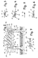
- Fig. 2
- in schematischer Darstellung die erfindungsgemäße Erdungseinrichtung, die in einem Doppelboden und einem Technikgeschoß des Reinraumes gemäß Fig. 1 vorgesehen ist,
- Fig. 3 bis Fig. 7
- unterschiedliche Verbindungen und Anschlüsse der Erdungseinrichtung.
Claims (11)
- Erdungseinrichtung mit Erdungsleitern (14, 15), an die über Verbindungsleitungen (24) elektrisch leitende Teile (9) angeschlossen sind und die über wenigstens eine Ableitung (25) mit dem Untergrund verbunden sind, wobei die Erdungsleiter (14, 15) flexible Leitungen sind, die durch Anschlußklemmen (17) leitend miteinander verbunden sind,
dadurch gekennzeichnet, daß die insbesondere für den Reinraumbereich vorgesehenen Erdungsleiter (14, 15) einander kreuzen und an den Kreuzungspunkten (16) mit den Anschlußklemmen (17) leitend miteinander verbunden sind. - Erdungseinrichtung nach Anspruch 1,
dadurch gekennzeichnet, daß die Erdungsleiter (14, 15) einen Isoliermantel haben, der einzelne Leitungen umgibt. - Erdungseinrichtung nach Anspruch 1 oder 2,
dadurch gekennzeichnet, daß die Anschlußklemme (17) den Isoliermantel des Erdungsleiters (14, 15) durchdringt. - Erdungseinrichtung nach einem der Ansprüche 1 bis 3,
dadurch gekennzeichnet, daß die Anschlußklemme (17) aus zwei gegeneinander verspannbaren Klemmteilen besteht. - Erdungseinrichtung nach Anspruch 4,
dadurch gekennzeichnet, daß zumindest der eine, vorzugsweise beide Klemmteile mit metallischen Zähnen versehen ist (sind). - Erdungseinrichtung nach einem der Ansprüche 1 bis 5,
dadurch gekennzeichnet, daß die Erdungsleiter (14, 15) im Rastermaß verlegt sind. - Erdungseinrichtung nach einem der Ansprüche 1 bis 6,
dadurch gekennzeichnet, daß die Verbindungsleitung (24) flexibel ausgebildet ist. - Erdungseinrichtung nach einem der Ansprüche 1 bis 7,
dadurch gekennzeichnet, daß die Erdungseinrichtung (10) über wenigstens eine flexible Leitung (25) mit der Ableitung (27, 32) verbunden ist. - Erdungseinrichtung nach Anspruch 8,
dadurch gekennzeichnet, daß die flexible Leitung (25) mit den Anschlußklemmen (17) an die Erdungseinrichtung (10) und an die Ableitung (27, 32) angeschlossen ist. - Erdungseinrichtung nach einem der Ansprüche 1 bis 9,
dadurch gekennzeichnet, daß die Erdungseinrichtung (10) in einem Boden (5) eines Reinraumes (1) untergebracht ist. - Erdungseinrichtung nach einem der Ansprüche 1 bis 9,
dadurch gekennzeichnet, daß die Erdungseinrichtung (10) in einem Deckenbereich des Reinraumes (1) angeordnet ist.
Applications Claiming Priority (2)
| Application Number | Priority Date | Filing Date | Title |
|---|---|---|---|
| DE29619800U | 1996-11-14 | ||
| DE29619800U DE29619800U1 (de) | 1996-11-14 | 1996-11-14 | Erdungseinrichtung, insbesondere für den Reinraumbereich |
Publications (2)
| Publication Number | Publication Date |
|---|---|
| EP0843382A1 EP0843382A1 (de) | 1998-05-20 |
| EP0843382B1 true EP0843382B1 (de) | 2002-01-09 |
Family
ID=8031934
Family Applications (1)
| Application Number | Title | Priority Date | Filing Date |
|---|---|---|---|
| EP97117555A Expired - Lifetime EP0843382B1 (de) | 1996-11-14 | 1997-10-10 | Erdungseinrichtung, insbesondere für den Reinraumbereich |
Country Status (5)
| Country | Link |
|---|---|
| US (1) | US5954524A (de) |
| EP (1) | EP0843382B1 (de) |
| DE (2) | DE29619800U1 (de) |
| ES (1) | ES2166496T3 (de) |
| TW (1) | TW348333B (de) |
Families Citing this family (5)
| Publication number | Priority date | Publication date | Assignee | Title |
|---|---|---|---|---|
| EP3066685B8 (de) * | 2013-11-05 | 2020-08-05 | ABB Power Grids Switzerland AG | Bodensystem für ein hochspannungshalbleiterventil |
| CN105375127B (zh) * | 2015-12-16 | 2018-01-23 | 安徽华电工程咨询设计有限公司 | 一种变电站中打接地深井方式的降低接地电阻方法 |
| CN107132455B (zh) * | 2017-05-26 | 2019-07-05 | 云南电网有限责任公司电力科学研究院 | 一种基于地线电流注入的变电站接地网性能评估方法 |
| CN106950456B (zh) * | 2017-05-26 | 2019-07-26 | 云南电网有限责任公司电力科学研究院 | 一种基于人工短路实验的变电站接地网性能评估方法 |
| DE102022116541A1 (de) * | 2022-07-01 | 2024-01-04 | Dehn Se | Erdungsanlagen-Anschlussklemmbaugruppe, Erdungsanlage sowie Verfahren zur Herstellung einer Klemmverbindung |
Family Cites Families (16)
| Publication number | Priority date | Publication date | Assignee | Title |
|---|---|---|---|---|
| US3638404A (en) * | 1969-09-30 | 1972-02-01 | Westinghouse Electric Corp | Vertical laminar-flow clean room of flexible design |
| US3720903A (en) * | 1971-05-27 | 1973-03-13 | Amp Inc | Filter assembly for printed circuit board connector |
| US3848956A (en) * | 1972-03-08 | 1974-11-19 | Fargo Mfg Co Inc | Self-sealing underground tap connector |
| US4140961A (en) * | 1977-06-21 | 1979-02-20 | Mitsubishi Denki Kabushiki Kaisha | Shunt circuit for an insulation type current transformer to adapt to a wide-band of frequency |
| JPS55132451A (en) * | 1979-04-03 | 1980-10-15 | Nissan Motor Co Ltd | Speed change control device for automatic speed changer |
| FR2456401A1 (fr) * | 1979-05-11 | 1980-12-05 | Goro | Cosse pour le raccordement de cables electriques sur un piquet de mise a la terre |
| US4325598A (en) * | 1979-12-21 | 1982-04-20 | Diamond Communication Products, Inc. | Ground clamp for grounding coaxial cable |
| DE3305363C2 (de) * | 1983-02-17 | 1991-09-26 | Johann 8438 Berg Pröpster | Mehrteilige Blechschraube für Blitzschutz |
| DE3510370A1 (de) * | 1985-03-22 | 1986-09-25 | kabelmetal electro GmbH, 3000 Hannover | Verfahren zum verbinden von zwei elektrischen leitungen |
| US4928210A (en) * | 1986-10-24 | 1990-05-22 | Kabushiki Kaisha Hybec | Linear lamp unit with contacts at both ends |
| JP2895130B2 (ja) * | 1989-01-23 | 1999-05-24 | アメリカン、インバイランメンタル、システムズ、インコーポレーテッド | ほゞ閉鎖された利用区域を選択された特性に調和する装置および方法 |
| US5231357A (en) * | 1990-05-09 | 1993-07-27 | Panduit Corp. | Apparatus for testing a wire harness and method of use |
| GB2247575B (en) * | 1990-08-07 | 1994-08-17 | Daiichi Denso Buhin | Conducting connector device |
| JP2929405B2 (ja) * | 1993-04-16 | 1999-08-03 | 矢崎総業株式会社 | スプリング内蔵の平型端子構造 |
| US5346403A (en) * | 1993-07-22 | 1994-09-13 | Itt Corporation | Connector grounding arrangement |
| US5673522A (en) * | 1994-03-25 | 1997-10-07 | Guilford, Inc. | Junction box forlow profile raised panel flooring |
-
1996
- 1996-11-14 DE DE29619800U patent/DE29619800U1/de not_active Expired - Lifetime
-
1997
- 1997-10-10 EP EP97117555A patent/EP0843382B1/de not_active Expired - Lifetime
- 1997-10-10 ES ES97117555T patent/ES2166496T3/es not_active Expired - Lifetime
- 1997-10-10 DE DE59705966T patent/DE59705966D1/de not_active Expired - Fee Related
- 1997-10-16 TW TW086115213A patent/TW348333B/zh not_active IP Right Cessation
- 1997-11-14 US US08/970,929 patent/US5954524A/en not_active Expired - Fee Related
Also Published As
| Publication number | Publication date |
|---|---|
| ES2166496T3 (es) | 2002-04-16 |
| EP0843382A1 (de) | 1998-05-20 |
| US5954524A (en) | 1999-09-21 |
| DE59705966D1 (de) | 2002-02-14 |
| DE29619800U1 (de) | 1997-01-09 |
| TW348333B (en) | 1998-12-21 |
Similar Documents
| Publication | Publication Date | Title |
|---|---|---|
| EP0396936B1 (de) | Einrichtung zum Schutz elektrischer Anlagen | |
| DE69736043T2 (de) | Geerdete flexible Schaltung mit verbesserten Impedanzeigenschaften | |
| EP0586841A1 (de) | Printplatte und Montagemodul für einen Anschluss abgeschirmter Leiter und Verteilersysteme im Schwachstrom-Anlagebau | |
| EP2683034A1 (de) | Verfahren zum elektrisch leitenden Verbinden der elektrischen Leiter von zwei Hochspannungskabeln | |
| DE2048104A1 (de) | Verteilerleiste für elektrische Anlagen, insbesondere Fernsprechanlagen | |
| DE19617114C2 (de) | Erdungsmodul | |
| EP0843382B1 (de) | Erdungseinrichtung, insbesondere für den Reinraumbereich | |
| DE3201142A1 (de) | Steckverbinder | |
| DE19604564C1 (de) | Anschlußdose für ein Datennetz | |
| DE2251020C3 (de) | Anschlußvorrichtung | |
| DE3001870C2 (de) | ||
| DE4008417A1 (de) | Vorrichtung zur verbindung der elektrischen anschluesse von kondensatoren | |
| EP3570392A1 (de) | Überspannungsableiteranordnung mit mehreren, in einem gehäuse befindlichen überspannungsableitern und interner verdrahtung zum schutz von niederspannungsversorgungssystemen | |
| DE19836195C1 (de) | Anschlußdose für ein Datennetz | |
| EP0778711A2 (de) | Steckverteiler, insbesondere für Datenübertragungsnetze | |
| EP3861188B1 (de) | Elektrifizierte leistenanordnung | |
| EP1566864B1 (de) | Steckdosenmodul für einen Stativkopf eines medizinischen Deckenstativs | |
| EP0397062A2 (de) | Einrichtung zum Schutz elektrischer Anlagen | |
| DE19534039C2 (de) | Anschlußdose für ein Datennetz | |
| EP3232513B1 (de) | System zur ausgleichung von elektrischen potentialgefällen sowie potentialausgleichsklemme hierfür | |
| DE19646107C5 (de) | Kontaktierungsanordnung für mehradrige Flachkabel | |
| DE4238867A1 (de) | Zentralelektrik | |
| DE60003259T2 (de) | Anschlussdose für elektrische Installationen | |
| DE19525801A1 (de) | Vorrichtung zum elektrisch leitenden Verbinden von zwei elektrischen Leitungen | |
| EP2673847B1 (de) | Direktsteckverbinder zur elektrischen direktkontaktierung einer leiterplatte |
Legal Events
| Date | Code | Title | Description |
|---|---|---|---|
| PUAI | Public reference made under article 153(3) epc to a published international application that has entered the european phase |
Free format text: ORIGINAL CODE: 0009012 |
|
| AK | Designated contracting states |
Kind code of ref document: A1 Designated state(s): BE DE ES FR GB IE IT NL PT SE |
|
| AX | Request for extension of the european patent |
Free format text: AL;LT;LV;RO;SI |
|
| 17P | Request for examination filed |
Effective date: 19981021 |
|
| AKX | Designation fees paid |
Free format text: BE DE ES FR GB IE IT NL PT SE |
|
| RBV | Designated contracting states (corrected) |
Designated state(s): BE DE ES FR GB IE IT NL PT SE |
|
| 17Q | First examination report despatched |
Effective date: 19991206 |
|
| GRAG | Despatch of communication of intention to grant |
Free format text: ORIGINAL CODE: EPIDOS AGRA |
|
| GRAG | Despatch of communication of intention to grant |
Free format text: ORIGINAL CODE: EPIDOS AGRA |
|
| GRAH | Despatch of communication of intention to grant a patent |
Free format text: ORIGINAL CODE: EPIDOS IGRA |
|
| ITF | It: translation for a ep patent filed |
Owner name: INTERPATENT ST.TECN. BREV. |
|
| RAP1 | Party data changed (applicant data changed or rights of an application transferred) |
Owner name: M+W ZANDER FACILITY ENGINEERING GMBH |
|
| GRAH | Despatch of communication of intention to grant a patent |
Free format text: ORIGINAL CODE: EPIDOS IGRA |
|
| GRAA | (expected) grant |
Free format text: ORIGINAL CODE: 0009210 |
|
| REG | Reference to a national code |
Ref country code: GB Ref legal event code: IF02 |
|
| AK | Designated contracting states |
Kind code of ref document: B1 Designated state(s): BE DE ES FR GB IE IT NL PT SE |
|
| REG | Reference to a national code |
Ref country code: IE Ref legal event code: FG4D Free format text: GERMAN |
|
| REF | Corresponds to: |
Ref document number: 59705966 Country of ref document: DE Date of ref document: 20020214 |
|
| PG25 | Lapsed in a contracting state [announced via postgrant information from national office to epo] |
Ref country code: SE Free format text: LAPSE BECAUSE OF FAILURE TO SUBMIT A TRANSLATION OF THE DESCRIPTION OR TO PAY THE FEE WITHIN THE PRESCRIBED TIME-LIMIT Effective date: 20020409 Ref country code: PT Free format text: LAPSE BECAUSE OF FAILURE TO SUBMIT A TRANSLATION OF THE DESCRIPTION OR TO PAY THE FEE WITHIN THE PRESCRIBED TIME-LIMIT Effective date: 20020409 |
|
| REG | Reference to a national code |
Ref country code: ES Ref legal event code: FG2A Ref document number: 2166496 Country of ref document: ES Kind code of ref document: T3 |
|
| GBT | Gb: translation of ep patent filed (gb section 77(6)(a)/1977) |
Effective date: 20020405 |
|
| ET | Fr: translation filed | ||
| PGFP | Annual fee paid to national office [announced via postgrant information from national office to epo] |
Ref country code: IE Payment date: 20020926 Year of fee payment: 6 |
|
| PGFP | Annual fee paid to national office [announced via postgrant information from national office to epo] |
Ref country code: GB Payment date: 20021009 Year of fee payment: 6 |
|
| PGFP | Annual fee paid to national office [announced via postgrant information from national office to epo] |
Ref country code: ES Payment date: 20021010 Year of fee payment: 6 |
|
| PGFP | Annual fee paid to national office [announced via postgrant information from national office to epo] |
Ref country code: FR Payment date: 20021011 Year of fee payment: 6 |
|
| PGFP | Annual fee paid to national office [announced via postgrant information from national office to epo] |
Ref country code: BE Payment date: 20021030 Year of fee payment: 6 |
|
| PGFP | Annual fee paid to national office [announced via postgrant information from national office to epo] |
Ref country code: NL Payment date: 20021031 Year of fee payment: 6 |
|
| PLBE | No opposition filed within time limit |
Free format text: ORIGINAL CODE: 0009261 |
|
| STAA | Information on the status of an ep patent application or granted ep patent |
Free format text: STATUS: NO OPPOSITION FILED WITHIN TIME LIMIT |
|
| PGFP | Annual fee paid to national office [announced via postgrant information from national office to epo] |
Ref country code: DE Payment date: 20021227 Year of fee payment: 6 |
|
| 26N | No opposition filed | ||
| PG25 | Lapsed in a contracting state [announced via postgrant information from national office to epo] |
Ref country code: IE Free format text: LAPSE BECAUSE OF NON-PAYMENT OF DUE FEES Effective date: 20031010 Ref country code: GB Free format text: LAPSE BECAUSE OF NON-PAYMENT OF DUE FEES Effective date: 20031010 |
|
| PG25 | Lapsed in a contracting state [announced via postgrant information from national office to epo] |
Ref country code: ES Free format text: LAPSE BECAUSE OF NON-PAYMENT OF DUE FEES Effective date: 20031011 |
|
| PG25 | Lapsed in a contracting state [announced via postgrant information from national office to epo] |
Ref country code: BE Free format text: LAPSE BECAUSE OF NON-PAYMENT OF DUE FEES Effective date: 20031031 |
|
| BERE | Be: lapsed |
Owner name: *M+W ZANDER FACILITY ENGINEERING G.M.B.H. Effective date: 20031031 |
|
| PG25 | Lapsed in a contracting state [announced via postgrant information from national office to epo] |
Ref country code: NL Free format text: LAPSE BECAUSE OF NON-PAYMENT OF DUE FEES Effective date: 20040501 Ref country code: DE Free format text: LAPSE BECAUSE OF NON-PAYMENT OF DUE FEES Effective date: 20040501 |
|
| GBPC | Gb: european patent ceased through non-payment of renewal fee |
Effective date: 20031010 |
|
| PG25 | Lapsed in a contracting state [announced via postgrant information from national office to epo] |
Ref country code: FR Free format text: LAPSE BECAUSE OF NON-PAYMENT OF DUE FEES Effective date: 20040630 |
|
| NLV4 | Nl: lapsed or anulled due to non-payment of the annual fee |
Effective date: 20040501 |
|
| REG | Reference to a national code |
Ref country code: IE Ref legal event code: MM4A |
|
| REG | Reference to a national code |
Ref country code: FR Ref legal event code: ST |
|
| REG | Reference to a national code |
Ref country code: ES Ref legal event code: FD2A Effective date: 20031011 |
|
| PG25 | Lapsed in a contracting state [announced via postgrant information from national office to epo] |
Ref country code: IT Free format text: LAPSE BECAUSE OF NON-PAYMENT OF DUE FEES;WARNING: LAPSES OF ITALIAN PATENTS WITH EFFECTIVE DATE BEFORE 2007 MAY HAVE OCCURRED AT ANY TIME BEFORE 2007. THE CORRECT EFFECTIVE DATE MAY BE DIFFERENT FROM THE ONE RECORDED. Effective date: 20051010 |