EP3860465B1 - Metallinjektionsform für stethoskopbruststück - Google Patents
Metallinjektionsform für stethoskopbruststück Download PDFInfo
- Publication number
- EP3860465B1 EP3860465B1 EP19869357.4A EP19869357A EP3860465B1 EP 3860465 B1 EP3860465 B1 EP 3860465B1 EP 19869357 A EP19869357 A EP 19869357A EP 3860465 B1 EP3860465 B1 EP 3860465B1
- Authority
- EP
- European Patent Office
- Prior art keywords
- diaphragm
- stethoscope
- stethoscope chestpiece
- molded body
- chestpiece
- Prior art date
- Legal status (The legal status is an assumption and is not a legal conclusion. Google has not performed a legal analysis and makes no representation as to the accuracy of the status listed.)
- Active
Links
Images


Classifications
-
- A—HUMAN NECESSITIES
- A61—MEDICAL OR VETERINARY SCIENCE; HYGIENE
- A61B—DIAGNOSIS; SURGERY; IDENTIFICATION
- A61B7/00—Instruments for auscultation
- A61B7/02—Stethoscopes
-
- B—PERFORMING OPERATIONS; TRANSPORTING
- B22—CASTING; POWDER METALLURGY
- B22F—WORKING METALLIC POWDER; MANUFACTURE OF ARTICLES FROM METALLIC POWDER; MAKING METALLIC POWDER; APPARATUS OR DEVICES SPECIALLY ADAPTED FOR METALLIC POWDER
- B22F3/00—Manufacture of workpieces or articles from metallic powder characterised by the manner of compacting or sintering; Apparatus specially adapted therefor ; Presses and furnaces
- B22F3/10—Sintering only
- B22F3/1017—Multiple heating or additional steps
- B22F3/1021—Removal of binder or filler
-
- B—PERFORMING OPERATIONS; TRANSPORTING
- B22—CASTING; POWDER METALLURGY
- B22F—WORKING METALLIC POWDER; MANUFACTURE OF ARTICLES FROM METALLIC POWDER; MAKING METALLIC POWDER; APPARATUS OR DEVICES SPECIALLY ADAPTED FOR METALLIC POWDER
- B22F3/00—Manufacture of workpieces or articles from metallic powder characterised by the manner of compacting or sintering; Apparatus specially adapted therefor ; Presses and furnaces
- B22F3/22—Manufacture of workpieces or articles from metallic powder characterised by the manner of compacting or sintering; Apparatus specially adapted therefor ; Presses and furnaces for producing castings from a slip
- B22F3/225—Manufacture of workpieces or articles from metallic powder characterised by the manner of compacting or sintering; Apparatus specially adapted therefor ; Presses and furnaces for producing castings from a slip by injection molding
-
- B—PERFORMING OPERATIONS; TRANSPORTING
- B22—CASTING; POWDER METALLURGY
- B22F—WORKING METALLIC POWDER; MANUFACTURE OF ARTICLES FROM METALLIC POWDER; MAKING METALLIC POWDER; APPARATUS OR DEVICES SPECIALLY ADAPTED FOR METALLIC POWDER
- B22F3/00—Manufacture of workpieces or articles from metallic powder characterised by the manner of compacting or sintering; Apparatus specially adapted therefor ; Presses and furnaces
- B22F3/22—Manufacture of workpieces or articles from metallic powder characterised by the manner of compacting or sintering; Apparatus specially adapted therefor ; Presses and furnaces for producing castings from a slip
- B22F3/227—Manufacture of workpieces or articles from metallic powder characterised by the manner of compacting or sintering; Apparatus specially adapted therefor ; Presses and furnaces for producing castings from a slip by organic binder assisted extrusion
-
- B—PERFORMING OPERATIONS; TRANSPORTING
- B22—CASTING; POWDER METALLURGY
- B22F—WORKING METALLIC POWDER; MANUFACTURE OF ARTICLES FROM METALLIC POWDER; MAKING METALLIC POWDER; APPARATUS OR DEVICES SPECIALLY ADAPTED FOR METALLIC POWDER
- B22F3/00—Manufacture of workpieces or articles from metallic powder characterised by the manner of compacting or sintering; Apparatus specially adapted therefor ; Presses and furnaces
- B22F3/24—After-treatment of workpieces or articles
-
- B—PERFORMING OPERATIONS; TRANSPORTING
- B22—CASTING; POWDER METALLURGY
- B22F—WORKING METALLIC POWDER; MANUFACTURE OF ARTICLES FROM METALLIC POWDER; MAKING METALLIC POWDER; APPARATUS OR DEVICES SPECIALLY ADAPTED FOR METALLIC POWDER
- B22F5/00—Manufacture of workpieces or articles from metallic powder characterised by the special shape of the product
- B22F5/10—Manufacture of workpieces or articles from metallic powder characterised by the special shape of the product of articles with cavities or holes, not otherwise provided for in the preceding subgroups
-
- B—PERFORMING OPERATIONS; TRANSPORTING
- B22—CASTING; POWDER METALLURGY
- B22F—WORKING METALLIC POWDER; MANUFACTURE OF ARTICLES FROM METALLIC POWDER; MAKING METALLIC POWDER; APPARATUS OR DEVICES SPECIALLY ADAPTED FOR METALLIC POWDER
- B22F7/00—Manufacture of composite layers, workpieces, or articles, comprising metallic powder, by sintering the powder, with or without compacting wherein at least one part is obtained by sintering or compression
- B22F7/06—Manufacture of composite layers, workpieces, or articles, comprising metallic powder, by sintering the powder, with or without compacting wherein at least one part is obtained by sintering or compression of composite workpieces or articles from parts, e.g. to form tipped tools
- B22F7/062—Manufacture of composite layers, workpieces, or articles, comprising metallic powder, by sintering the powder, with or without compacting wherein at least one part is obtained by sintering or compression of composite workpieces or articles from parts, e.g. to form tipped tools involving the connection or repairing of preformed parts
-
- B—PERFORMING OPERATIONS; TRANSPORTING
- B22—CASTING; POWDER METALLURGY
- B22F—WORKING METALLIC POWDER; MANUFACTURE OF ARTICLES FROM METALLIC POWDER; MAKING METALLIC POWDER; APPARATUS OR DEVICES SPECIALLY ADAPTED FOR METALLIC POWDER
- B22F7/00—Manufacture of composite layers, workpieces, or articles, comprising metallic powder, by sintering the powder, with or without compacting wherein at least one part is obtained by sintering or compression
- B22F7/06—Manufacture of composite layers, workpieces, or articles, comprising metallic powder, by sintering the powder, with or without compacting wherein at least one part is obtained by sintering or compression of composite workpieces or articles from parts, e.g. to form tipped tools
- B22F7/08—Manufacture of composite layers, workpieces, or articles, comprising metallic powder, by sintering the powder, with or without compacting wherein at least one part is obtained by sintering or compression of composite workpieces or articles from parts, e.g. to form tipped tools with one or more parts not made from powder
-
- G—PHYSICS
- G10—MUSICAL INSTRUMENTS; ACOUSTICS
- G10K—SOUND-PRODUCING DEVICES; METHODS OR DEVICES FOR PROTECTING AGAINST, OR FOR DAMPING, NOISE OR OTHER ACOUSTIC WAVES IN GENERAL; ACOUSTICS NOT OTHERWISE PROVIDED FOR
- G10K13/00—Cones, diaphragms, or the like, for emitting or receiving sound in general
-
- B—PERFORMING OPERATIONS; TRANSPORTING
- B22—CASTING; POWDER METALLURGY
- B22F—WORKING METALLIC POWDER; MANUFACTURE OF ARTICLES FROM METALLIC POWDER; MAKING METALLIC POWDER; APPARATUS OR DEVICES SPECIALLY ADAPTED FOR METALLIC POWDER
- B22F3/00—Manufacture of workpieces or articles from metallic powder characterised by the manner of compacting or sintering; Apparatus specially adapted therefor ; Presses and furnaces
- B22F3/24—After-treatment of workpieces or articles
- B22F2003/241—Chemical after-treatment on the surface
- B22F2003/242—Coating
-
- B—PERFORMING OPERATIONS; TRANSPORTING
- B22—CASTING; POWDER METALLURGY
- B22F—WORKING METALLIC POWDER; MANUFACTURE OF ARTICLES FROM METALLIC POWDER; MAKING METALLIC POWDER; APPARATUS OR DEVICES SPECIALLY ADAPTED FOR METALLIC POWDER
- B22F3/00—Manufacture of workpieces or articles from metallic powder characterised by the manner of compacting or sintering; Apparatus specially adapted therefor ; Presses and furnaces
- B22F3/24—After-treatment of workpieces or articles
- B22F2003/247—Removing material: carving, cleaning, grinding, hobbing, honing, lapping, polishing, milling, shaving, skiving, turning the surface
-
- B—PERFORMING OPERATIONS; TRANSPORTING
- B22—CASTING; POWDER METALLURGY
- B22F—WORKING METALLIC POWDER; MANUFACTURE OF ARTICLES FROM METALLIC POWDER; MAKING METALLIC POWDER; APPARATUS OR DEVICES SPECIALLY ADAPTED FOR METALLIC POWDER
- B22F2998/00—Supplementary information concerning processes or compositions relating to powder metallurgy
- B22F2998/10—Processes characterised by the sequence of their steps
-
- B—PERFORMING OPERATIONS; TRANSPORTING
- B22—CASTING; POWDER METALLURGY
- B22F—WORKING METALLIC POWDER; MANUFACTURE OF ARTICLES FROM METALLIC POWDER; MAKING METALLIC POWDER; APPARATUS OR DEVICES SPECIALLY ADAPTED FOR METALLIC POWDER
- B22F2999/00—Aspects linked to processes or compositions used in powder metallurgy
-
- B—PERFORMING OPERATIONS; TRANSPORTING
- B22—CASTING; POWDER METALLURGY
- B22F—WORKING METALLIC POWDER; MANUFACTURE OF ARTICLES FROM METALLIC POWDER; MAKING METALLIC POWDER; APPARATUS OR DEVICES SPECIALLY ADAPTED FOR METALLIC POWDER
- B22F5/00—Manufacture of workpieces or articles from metallic powder characterised by the special shape of the product
- B22F5/06—Manufacture of workpieces or articles from metallic powder characterised by the special shape of the product of threaded articles, e.g. nuts
Definitions
- Stethoscopes having non-symmetrical shapes are generally produced using an investment casting process.
- the investment casting process can generally involve molding a wax piece, forming a wax tree, dipping the wax tree into a sand slurry, melting the wax to form a shell, pouring the liquid metal, breaking off the shell, cutting off the tree, tumbling, cutting off a gate, grinding, followed by heat treatment. This process can cause defects such as pits and voids.
- MIM metal injection molding
- PIM powder injection molding
- US 2003/201138 A1 relates to a chestpiece for a stethoscope.
- the chestpiece has a mix of desirable properties through being fabricated from the group of materials known as "high gravity compounds". These compounds are prepared by loading various plastic resins with high density metal powders. In spite of the metallic content, appropriate compounds can be injection molded, providing economic and aesthetic advantages.
- US 2015/164465 A1 relates to a detection head of a stethoscope that comprises a detection head body and a sound guiding conduit in the detection head body.
- the sound guiding conduit comprises a sound collecting surface, a sound guiding pore, and a lateral sound guiding aperture.
- the sound collecting surface, the sound guiding pore, and the lateral sound guiding aperture are disposed on the detection head body, and in combination with each other.
- At least a part of the detection head body is made of a second density material.
- the density of the material of a sound guiding layer on the sound collecting surface is greater than that of the second density material.
- the invention which relates to a method of making a metal stethoscope, is defined by the features of the independent claim. Preferred embodiments are defined in the dependent claims.
- metal powder injection molding has the disadvantages that anisotropies sometimes occur in the casting mould in the case of relatively large workpieces (e.g., greater than 50g) and that a separate step for removing the binder has to be carried out.
- MIM techniques can cause cracking or discoloration. This is particularly true with stethoscopes because a stethoscope chestpiece has thick and thin sections, which present issues during debinding as the difference in heating and cooling rates can generate stresses in the material causing cracks. This makes MIM ill-suited to applications where aesthetics (such as smooth mirrored surfaces) are desirable.
- the present disclosure relates to a stethoscope comprising a stethoscope chestpiece comprising a body member having a bottom surface.
- the stethoscope chestpiece comprises an ejector mark disposed on the bottom surface.
- the stethoscope chestpiece has a weight of at least 50 g, a surface roughness (R a ) no greater than 1.6 microns in an unpolished state, and reflectivity (%R) of at least 60% in an unpolished state.
- the stethoscope chestpiece can be produced by injection molding, extruding, or pressing a metallic thermoplastic composition into a mould forming a green molded body.
- the stethoscope chestpiece can also be produced by debinding a portion of binder material from green molded body at a temperature in the range of 100 to 200 °C over a period from 4 to 12 hours in a nitrogen-comprising atmosphere forming a brown molded body without reducing the temperature significantly.
- the stethoscope chestpiece can also be produced by sintering the brown molded body a a temperature in the range from 1100 to 1500°C over a period of from 6 to 10 hours in a hydrogen or argon atmosphere to form the stethoscope chestpiece.
- the present disclosure also relates to a method of manufacturing.
- the present disclosure relates to a method of using metal injection molding to manufacture a stethoscope chestpiece.
- the stethoscope chestpiece has shown improve crack resistance by using process control conditions, feedstock selection, and ejector marks on the stethoscope chestpiece.
- the stethoscope chestpiece can exhibit properties that distinguish the stethoscope from traditional investment casting techniques as described herein.
- acoustical stiffness of the diaphragm designates the mechanical stiffness of the diaphragm as influenced by the mechanical stiffness of the diaphragm material itself, the thickness of the diaphragm, the shape of the diaphragm, the diameter of the diaphragm, and the manner in which the diaphragm is attached to the stethoscope chestpiece.
- plane of the diaphragm refers to the generally planar surface of the diaphragm.
- Non-symmetrical shapes are preferred.
- a symmetrical shape can be symmetric on a plurality of axes rotated about top-bottom axis.
- a non-symmetrical shape can be symmetric about only one axis (e.g., the axis intersecting a stem fitting, axis formed along the line 3-3 in FIG. 2 but not symmetrical along line 5-5.
- Non-symmetrical shapes generally cannot be lathed. Examples of non-symmetric shares of stethoscope chestpiece include the Master Cardiology, Master Classic, and the Classic SE by 3M (Saint Paul, MN).
- the stethoscope chestpiece may be a single-sided meaning that only one diaphragm can be positioned on the stethoscope chestpiece.
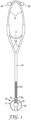
- stethoscope chestpiece 10 comprises body member 11 formed of metallic thermoplastic compositions.
- Stethoscope chestpiece 10 is attached to a conventional headset such as those commercially available under the trade designation Littman by 3M (St. Paul, MN) which comprises elongated flexible tubing 12 which contains dual air passages 13 which run side-by-side for a major portion of the distance between stethoscope chestpiece 10 and ear tubes 14.
- a conventional headset such as those commercially available under the trade designation Littman by 3M (St. Paul, MN) which comprises elongated flexible tubing 12 which contains dual air passages 13 which run side-by-side for a major portion of the distance between stethoscope chestpiece 10 and ear tubes 14.
- the upper end of flexible tubing 12 bifurcates into coupling arms
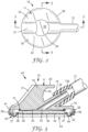
- the body member 11 comprises a substantially disk-like portion 18 and column 19 emanating therefrom as shown in FIG. 2 .
- Top 20 of column 19 is substantially flat.
- Front section 21 of column 19 is sloped away from top 20, is concave in configuration and is curved to meet the top surface of disk-like portion 18.
- Side sections 22 and 23 and back section 24 are arcuate in configuration.
- the shape of body member 11 permits a clinician to grasp it in one of two particularly convenient ways.
- the clinician may grasp column 19 from the top with the index finger being placed on front section 21 and each of the thumb and the middle finger being placed on opposite sides of column 19 adjacent top 20.
- the clinician may place the index finger and middle finger adjacent disk 18 on opposite sides of column 19 (with fitting 15 passing between those fingers).
- body member 11 has a first generally bell-shaped recess 25, the recess 25 being defined by side wall 26, outer rim portion 27, and inner central portion or plate-like member 28 (which can be the immobilizing means).
- Second conical-shaped recess 29 is defined by inner central portion or plate-like member 28 which is integral with body member 11 and has a centrally sloping depression in its surface and optional O-ring 31 which is situated circumjacent plate-like member 28 and retained thereon.
- the circumjacent plate-like member 28 itself can be raised further from a plane formed by the major surface of the portion adjacent to the outer rim portion 27 (the major surface contacting the compliant ring 35), thus negating the need of the O-ring 31.
- Body member 11 also comprises bore 32 extending from fitting 15 through body member 11 to aperture 33 within bell-shaped first recess 25 and conical-shaped second recess 29.
- the body member 11 can have an outside surface or top surface 42 at least partially defined as a region that a clinician can touch.
- the outside surface 42 includes the column 19.
- the outside surface 42 is generally polished since this surface is seen by the clinician.
- the body member 11 may have an inner surface or bottom surface 43.
- the bottom surface 43 includes a major surface of both the recess 25 and the conical-shaped second recess 29. Generally, the bottom surface 43 is overlaid by the diaphragm 34 and is not polished or seen by the clinician.
- the bottom surface 43 can be planar and forms a plane defined by at least one circumference.
- Diaphragm 34 may overlay the entirety of second conical-shaped recess 29 (and inner central portion or plate-like member 28) and at least a portion of first bell-shaped recess 25 to permit contact of diaphragm 34 with O-ring 31.
- Diaphragm 34 may comprise any material which is known in the art as being suitable for use as a diaphragm. Examples of suitable materials include plastics such as polyester, fiberglass-reinforced plastics, and polystyrene and metals such as stainless steel.
- a suitable thickness for diaphragm 34 is about 5 to 20 mils (0.013 to 0.051 centimeters).
- the preferred thickness for diaphragm 34 is about 10 to 12 mils (0.025 to 0.030 centimeters).
- a preferred diaphragm comprises a 10 mil-thick (0.025 centimeter-thick) epoxy resin-fiberglass laminate.
- suspension member or compliant ring 35 which suspends diaphragm 34 across the first bell-shaped recess 25 and allows diaphragm 34 to move in a direction generally perpendicular to the plane of the diaphragm.
- Compliant ring 35 is generally horseshoe-shaped in cross-section having an inner edge 37 and an outer edge 38 on either side of curved portion 40.
- Compliant ring 35 is attached to peripheral edge portion 36 of diaphragm 34 at inner edge 37.
- Outer edge 38 is attached to first bell-shaped recess 25 by means of a retaining ring or plastic fitting 39 which engages notch 41 of body member 11.
- the notch 41 can have an edge having a square-like profile with non-rounded corners as a result of the finer resolution of MIM.
- the diaphragm 34 is constructed as a single piece, meaning that the diaphragm 34 is connected to the compliant ring 35 as described in U.S. Pub. No. US2018-0008227A1 .
- the response of stethoscope chestpiece 10 to low frequency and high frequency sounds is affected by several parameters.
- the thickness of diaphragm 34 affects the response and suitable thicknesses for diaphragm 34 have been discussed hereinabove.
- the relative dimensions of first bell-shaped recess 25 and second conical-shaped recess 29 affect the response. The following have been found to be suitable dimensions for first bell-shaped recess 25 and second conical-shaped recess 29.
- First bell-shaped recess 25 has a diameter (as defined by side wall 26) of 2 inches (5.10 centimeters) and has a volume (as defined by diaphragm 34 and compliant ring 35 when no pressure is exerted on the exterior surface of diaphragm 34) of approximately 0.325 in 3 (5.33 cm 3 ).
- Second conical-shaped recess 29 has a diameter (as defined by O-ring 31) of 1.5 inches (3.8 centimeters) and a volume (as defined by diaphragm 34 when it is in contact with O-ring 31) of approximately 0.059 in 3 (0.97 cm 3 ).
- diaphragm 34 travels from its equilibrium position to its position in which it is in contact with O-ring 31 is approximately 0.070 inches (0.18 centimeters).
- diaphragm 34 may be of a diameter which is greater than the diameter of second conical-shaped recess 29.
- a diaphragm having a 1.75 inch (4.45-centimeter) diameter has been found to be suitable in a stethoscope chestpiece comprising first bell-shaped recess 25 and second conical-shaped recess 29 of the above indicated dimensions.
- a compliant ring 35 which includes curved portion 40 having a radius of curvature of 0.047 inches (0.12 centimeters) has been found to provide the desired freedom of movement of diaphragm 34.
- FIG. 4 illustrates a flowchart of a method 400 of making a stethoscope.
- the method 400 includes making a chestpiece, e.g., blocks 410 through 420, and assembling the stethoscope, e.g., block 422.
- the method 400 can begin at block 410 where a green molded body is formed.
- the green molded body is a metallic thermoplastic and can be obtained by injection molding, extruding, or pressing of metallic thermoplastic compositions or thermoplastic molding compositions comprising metal powders.
- metal powders are powders of Fe, Al, Cu, Nb, Ti, Mn, V, Ni, Cr, Co, Mo, W and Si, and combinations thereof.
- Stethoscope chestpieces which are preferred are those which can be obtained from powder injection molding compositions, particularly preferably from powder injection molding compositions of Fe and Cr.
- injection molding also referred to as powder injection molding
- extrusion and “pressing” are used in the sense of processes from powder technology, in particular powder metallurgy, in which, for example, a shaped body from which the binder is subsequently removed and which is then sintered to produce the finished workpiece is produced by injection molding of a thermoplastic injection molding composition comprising metal or ceramic powder and a proportion of usually at least 30% by volume of a thermoplastic binder.
- the mould for metal injection molding is generally larger than the finished stethoscope chestpiece.
- the injection molding of the metallic thermoplastic composition can occur at an elevated temperature sufficient to bind portions of the metallic thermoplastic compositions inside of the mould.
- the mould is a hollow container used to give shape a molten metallic thermoplastic material, when the material cools and hardens.
- the mould is a negative impression of the intended stethoscope chestpiece.
- the mould as defined herein can be a negative of the stethoscope chestpiece described herein.
- the metallic thermoplastic composition can include both a binder.
- the polyoxymethalene homopolymers and copolymers mentioned as binders and their preparation are known to those skilled in the art and are described in the literature.
- the homopolymers are usually prepared by polymerization (mostly catalyzed polymerization) of formaldehyde or trioxane.
- a cyclic ether or a plurality of cyclic ethers is/are usually used as comonomer together with formaldehyde and/or trioxane in the polymerization, so that the polyoxymethylene chain with its sequence of (-OCH 2 )-units is interrupted by units in which more than one carbon atom is present between two oxygen atoms.
- cyclic ethers which are suitable as comonomers are ethylene oxide, 1,2-propylene oxide, 1,2-butylene oxide, 1,3-dioxane, 1,3-dioxolane, dioxepane, linear oligoformals and polyformals such as polydioxolane or polydioxepane and also oxymethylene terpolymers.
- the binder comprises at least 80% by weight of polyoxymethylene (POM) and can additionally comprise further polymers, for example polystyrene, polypropylene, polyethlene and ethylene-vinyl acetate copolymers and also further auxiliaries which may be necessary, e.g. dispersants, plasticizers and mold release agents.
- further polymers mentioned e.g. polystyrene, polypropylene, polyethylene and ethylene-vinyl acetate copolymers, and also any further auxiliaries which may be necessary, e.g. dispersants, plasticizers and mold release agents, are removed from the shaped part.
- the metallic thermoplastic composition may be commercially available under the trade designation Catamold, model: LG plus from BASF (Florham Park, NJ).
- the green molded body can be optionally removed, e.g., demolded, in block 412.
- the green molded body can be removed in order to allow shrinkage and avoid problems during the debinding and sintering process.
- the removal can include applying one or more ejectors (comprising ejector pins) to the green molded body to remove the green molded body from the mould. It may be beneficial for the ejectors to contact the part over the largest possible area and without tilting.
- the ejector pins can be any shape and be positioned roughly evenly along the stethoscope chestpiece. Preferably, the ejectors pins can contact an unseen or unpolished area of the stethoscope chestpiece such as the bottom.
- the green molded body can be removed via a vacuum method which may leave a positive protruding area within the green molded body.
- a portion of binder material from the green molded body is debound to form the brown molded body.
- thermal debinding or pyrolysis
- the green molded body is heated in a closely controlled oven up to a temperature just below the softening point of the binder.
- a binder can undergo gaseous decomposition.
- debinding can occur at or around 110 deg. C, which is below the melting range of polyacetal, 150°C - 170°C.
- the polymer can be directly converted from a solid into a gas.
- a residual amount (usually around 10 weight % of the original binder content) of an acid-resistant binder component may remain.
- the temperature of a debinding oven is from 100C to 200 C, 100 C to 140 C, preferably 110 - 120 C.
- Block 414 occurs in a nitrogen comprising atmosphere, wherein nitric acid and formaldehyde are vented.
- Solvent debinding is an alternative process that improves the debinding rate verses pyrolysis.
- the parts are immersed in liquid or vapor of an extracting solvent.
- the solvent accelerates the removal of binder from the parts and helps open-up porosity in the part.
- Solvent debinding still requires that the residual binder and solvent must be removed from the part thermally.
- Possible solvents may include nitric acid.
- a binder removal oven or debinding oven can be used.
- the binder removal oven is an oven through which the shaped bodies travel in a transport direction while being brought to the above-defined temperatures for the above-defined periods of time.
- debinding ovens are commercially available from manufacturers such as CMFunaces, Inc (Bloomfield, NJ) or Elnik Systems, LLC (Cedar Grove, NJ).
- debinding methods involve the transport from a first debinding oven to a second debinding oven, this may introduce partial cooling which was found to be detrimental.
- the method according to claim 1 of the present invention involves continuous debinding (e.g., debinding without transferring ovens or otherwise without significant drops in temperature). The debinding temperature is maintained within ⁇ 10 °C during the debinding period.
- the total debinding can occur between 4 to 12 hours, 4 to 10 hours, 4 to 8 hours, 4 to 7 hours, 4 to 6 hours, or 4 to 5 hours in a nitrogen-comprising atmosphere.
- the brown molded body is sintered at a temperature in the range from 1100 to 1500 °C over a period of from 6 to 10 hours to produce a stethoscope chestpiece (unpolished).
- the sintering occurs in a pure hydrogen or argon atmosphere to form the stethoscope chestpiece.
- the sintering time i.e. the hold time at the sintering temperature
- Sintering is preferably carried out so that the sintering process is shorter relative to debinding.
- the sintering process (including the heating ramp up phase but without the cooling phase) will be able to be concluded after 6 to 10 hours, 8 to 10 hours, 4 to 8 hours, 4 to 7 hours, or 4 to 6 hours for a stethoscope chestpiece.
- the total time in both the sintering process and debinding process can be between 6 to 10 hours, or 6 to 8 hours.
- sintering apparati may be used and are commercially available from manufacturers such as CMFunaces, Inc (Bloomfield, NJ) or Elnik Systems, LLC (Cedar Grove, NJ).
- any desired after-treatment for example sinter hardening, austenite formation, annealing, hardening, upgrading, carburization, case hardening, carbonitriding, nitriding, steam treatment, solution heat treatment, quenching in water or oil and/or hot isostatic pressing of the sintered shaped parts or a combination of these treatment steps, can be carried out.
- Some of these treatment steps for instance sinter hardening, nitriding or carbonitriding can also be carried out in a known way during sintering.
- the stethoscope chestpiece can be removed from the line and optionally shipped for polishing.
- the unpolished stethoscope chestpiece produced by injection molding can have properties that are unexpectedly better than those produced using investment casting techniques.
- the surface roughness of an injection molded stethoscope chestpiece is as follows:
- R z can be no greater than 10.4 microns, no greater than 10 microns, no greater than 9 microns, no greater than 8 microns, no greater than 7 microns, no greater than 6 microns, no greater than 5 microns, no greater than 4 microns, no greater than 3 microns.
- R a can be no greater than 1.6 microns, no greater than 1.5 microns, no greater than 1.4 microns, no greater than 1.3 microns, no greater than 1.2 microns, no greater than 1.1 microns, no greater than 1.0 microns.
- R m can be no greater than 12.4 microns, no greater than 12 microns, no greater than 11 microns, no greater than 10 microns, no greater than 9 microns, no greater than 8 microns, no greater than 7 microns, no greater than 6 microns, no greater than 5 microns, no greater than 4 microns, no greater than 3 microns.
- the surface roughness can be measured according to ASME B46.1-2009.
- the unpolished injection molded stethoscope chestpiece can have better manufacturing yields, improved finish, and corrosion resistance compared to an investment cast unpolished stethoscope chestpiece.
- the resulting stethoscope chestpiece can have a weight of at least 50 g, at least 55 g, at least 60 g, at least 70 g, at least 75 g, at least 80 g, at least 85 g, at least 90 g, or at least 94 g which is significantly heavier than smaller metal injection molded parts.
- the reflectance can be measured according to ASTM E1331-15.
- the unpolished injection molded stethoscope chestpiece can have a percent reflectance (%R) of at least 60%, at least 65%, at least 70%, at least 75%, at least 80%, at least 85%, at least 90%, at least 95%, at least 96%, at least 97%, at least 98%, or at least 99% at a wavelength of 400 to 650 nm.
- FIG. 9 illustrates an investment cast stethoscope chestpiece 900 side-by-side with a metal injection molded stethoscope chestpiece 901.
- the MIM stethoscope chestpiece 901 has a silver diffusely reflective finish versus the dull gray of the investment cast stethoscope chestpiece 900.
- the stethoscope chestpiece 418 can optionally be polished to further enhance the visual appearance of the stethoscope chestpiece. Polishing may produce a mirrored finish and allows any pits or surface roughness to be smoothed out. Finish on the mirror polished parts must be nearly perfect, e.g., no pits, bumps, scratches, blemishes, or stains.
- a film can also optionally be deposited onto the stethoscope chestpiece.
- Various thin metallic films can be applied using physical vapor deposition, or chroming. With physical vapor deposition, a brass-colored or black-colored finish can be applied to the stethoscope chestpiece.
- the stethoscope can be assembled.
- the stethoscope can be assembled by attaching a stem into the stem fitting or a portion of the stethoscope chestpiece, attaching tubing to the stem.
- the assembly can also include attaching a diaphragm to the stethoscope chestpiece. Once assembled, the stethoscope can be packaged in an appropriate packaging.
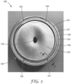
- FIG. 5 illustrates a unpolished injection molded stethoscope chestpiece 100, according to the present description.
- the stethoscope chestpiece 100 comprises a plurality of ejector marks 101, 102, 103, 104.
- the components of stethoscope chestpiece 100 can be similar to that of stethoscope chestpiece 10 in FIGS. 1-3 with similar numbering.
- recess 125 refers to a region between the outer edge 120
- the recess 125 can be recessed relative to the plate-like member 128 and the outer edge 120.
- the recess 125 can be defined by at least two side walls, side wall 126 and outer rim portion 127 which is shown tapering into a nadir 130.
- the nadir 130 may be a planar bottom surface.
- the ejector marks 101-104 can be marks from ejector pins or vacuums used in the demolding process.
- the ejector marks 101-104 may be equally spaced along the perimeter.
- the ejector marks 101-104 can also be spaced to allow even removal from a mould. Although 4 ejector marks are pictured, any number of ejector marks can be present.
- a stethoscope chestpiece can include at least one ejector mark, at least two ejector marks (i.e., a plurality of ejector marks), at least 4 ejector marks, etc.
- the total number of ejector marks may be an even number (e.g., 2, 4, 6).
- the ejector marks 103, 104 are positioned toward the front whereas ejector marks 101, 102 are positioned toward the back of the stethoscope chestpiece 100 (proximate to the stem cavity). Since the top of the stethoscope chestpiece forms a complex portion overhanging the stem, the ejector marks 103, 104 are closer together around the circumference of the recess 125 near the areas where force can be applied evenly to remove the top from a mould. Ejector marks 102 and 103 have a greater distance (at least 2 times) than the distance between 103 and 103 following the circumference of the recess 125.
- the ejector marks 101-104 may be positioned proximate to an edge 120, e.g., in recess 125 (e.g., FIGS. 6 and 7 , on plate-like member 128, or even positioned in the conical shaped second recess 129 as shown in FIG. 8 .
- the ejector marks can be any shape, however circular shapes can be useful in reducing corners and sharp edges. Although shown as relatively planar to the surface established by 128, the ejector marks 101-104 can be tapered depending on the mould shape.
- FIG. 6 illustrates the actual cross section corresponding to FIG. 5
- FIGS. 7 and 8 illustrate potential cross-sections along a similar view.
- the ejector marks 101-104 can be recessed relative to a plane of a surface or protruded.
- FIG. 6 illustrates recessed ejector mark 101 can be recessed relative to the nadir 130.
- the ejector mark 101 can have a bottom surface 106 and one or more side walls 107.
- the ejector mark 101 can have a depth of less than 4 mm, 3 mm, 2 mm, 1 mm, 0.8 mm, 0.6 mm, 0.4 mm, or 0.2 mm.
- the ejector mark 101 may be such that it does not extend to a depth beyond notch 41.
- the ejector marks 101-104 may have an area (measured by the bottom surface 106) of no greater than 5 mm 2 , no greater than 4 mm 2 , no greater than 3 mm 2 , no greater than 2 mm 2 , no greater than 1 mm 2 , no greater than 0.5 mm 2 .
- the ejector marks 101-104 can have a volume no greater than no greater than 5 mm 3 , no greater than 4 mm 3 , no greater than 3 mm 3 , no greater than 2 mm 3 , no greater than 1 mm 3 , no greater than 0.5 mm 3 .
- FIG. 7 illustrates a protruding ejector mark 131.
- the protruding ejector mark 131 can be formed by a vacuum assist of removing the green molded body from the mould.
- the ejector mark 131 can have a top surface 108 and one or more side walls 109.
- the protruding ejector mark 131 can have a side wall 109 height of no greater than the plate-like member 128.
- FIG. 8 illustrates a recessed ejector mark 132 (having bottom surface 111 and side wall 112) that is positioned within the conical-shaped recess 129.
- test method used for corrosion was modified from ASTM D 1654, Standard Test Method for Evaluation of Painted or Coated Specimens Subjected to Corrosive Environments. The samples were then visually inspected for rust or corrosion and the results recorded in Table 2.
- EX1 was prepared using a metal injection molding technique using 17-4PH F as a feedstock and molded into the same specifications as a Master Cardiology Stethoscope Chestpiece from 3M.
- the green molded body was sintered, continuously, for at least 4 hours at a temperature of at least 100C in a nitrogen atmosphere.
- the temperature of the sintering oven did not drop more than 10 deg. C while sintering.
- a mirror finish was achieved by polishing the chestpiece.
- EX2 was prepared using a metal injection molding technique using 316LA as a feedstock and molded into the same specifications as a Master Cardiology Stethoscope Chestpiece from 3M. The process conditions were the same as in EX1.
- EX3 was prepared lusing a metal injection molding technique using 316LG+ as a feedstock and molded into the same specifications as a Master Cardiology Stethoscope Chestpiece from 3M. The process conditions were the same as in EX1.
- CE1 was prepared using 17-4PH as a feedstock in an investment casting method used in production of existing Master Cardiology Stethoscope Chestpieces. A mirror finish was achieved by polishing the chestpiece.
- EX4 was prepared as in EX1 except that a smoke-colored coating was applied using physical vapor deposition (PVD).
- PVD physical vapor deposition
- EX5 was prepared as in EX2 except that a smoke-colored was applied using physical vapor deposition (PVD).
- PVD physical vapor deposition
- CE2 was prepared as in CE1 except that a smoke-colored was applied using physical vapor deposition (PVD).
- PVD physical vapor deposition
- EX1 it passed initial review of small lot quantities, but issues were noticed when larger production runs were inspected. During the inspection of the larger production lots, blemishes were noticed on about 30% of the parts reviewed and was considered an unacceptable yield for this process. The blemishes were seen on a variety of surfaces on the polished area of the chestpiece with varying severity. The blemishes were attributed to the material and had pitting which rules out the EX1 for the mirror polished application.
Landscapes
- Engineering & Computer Science (AREA)
- Manufacturing & Machinery (AREA)
- Mechanical Engineering (AREA)
- Health & Medical Sciences (AREA)
- Life Sciences & Earth Sciences (AREA)
- Acoustics & Sound (AREA)
- Physics & Mathematics (AREA)
- Biomedical Technology (AREA)
- Medical Informatics (AREA)
- Surgery (AREA)
- Animal Behavior & Ethology (AREA)
- General Health & Medical Sciences (AREA)
- Public Health (AREA)
- Veterinary Medicine (AREA)
- Molecular Biology (AREA)
- Heart & Thoracic Surgery (AREA)
- Chemical & Material Sciences (AREA)
- Composite Materials (AREA)
- Materials Engineering (AREA)
- Multimedia (AREA)
- Powder Metallurgy (AREA)
- Injection Moulding Of Plastics Or The Like (AREA)
Claims (3)
- Verfahren zum Herstellen eines Metallstethoskops, aufweisend:Spritzgießen, Extrudieren oder Pressen einer metallischen thermoplastischen Zusammensetzung in eine Form, die einen geformten Grünling ausbildet (410),Fortlaufendes Entbindern (414) eines Abschnitts von Bindematerial aus dem geformten Grünling bei einer Temperatur in einem Bereich von 100 bis 200 °C über einen Zeitraum von 4 bis 12 Stunden in einer Stickstoff aufweisenden Atmosphäre, wobei ein geformter Braunling ausgebildet wird, wobei die Temperatur während des Zeitraums innerhalb von ± 10 °C gehalten wird;Sintern (416) des geformten Bräunlings bei einer Temperatur in einem Bereich von 1100 bis 1500 °C über einen Zeitraum von 6 bis 10 Stunden in einer Wasserstoff- oder Argonatmosphäre, um das Stethoskop-Bruststück (10) auszubilden.
- Verfahren nach Anspruch 1, ferner aufweisend: Entfernen (412) des geformten Grünlings aus der Form durch Aufbringen von Auswerferstiften und Ausbilden einer Auswerfermarkierung (101, 102, 103, 104) in dem geformten Grünling.
- Verfahren nach Anspruch 1 oder 2, wobei die Form ein Negativausbilden aufweist:ein Körperelement (11), das eine erste allgemein glockenförmige Aussparung (25) mit einem inneren Mittelabschnitt (28), einem äußeren Randabschnitt (27) und einem Bohrloch (32) aufweist, das sich durch das Körperelement erstreckt, wobei es mit dem Mittelabschnitt der ersten Aussparung in Austausch steht;Arretierungsmittel, die auf dem Körperelement untergebracht sind und sich innerhalb der ersten Aussparung um den Mittelabschnitt herum befinden, wobei die Feststellmittel angepasst sind, um durch eine Membran (34) berührt zu werden, wenn die Membran in einer inneren Position ist, sodass ein Stethoskop-Bruststück (10) niederfrequente Töne durchlässt und hochfrequente Töne dämpft, wenn die Membran in der äußeren Position und zwischen der äußeren und der inneren Position ist, und wenn die Membran in der inneren Position ist, die akustische Steifigkeit der Membran ausreichend höher als die erste akustische Steifigkeit sein wird, sodass das Stethoskop-Bruststück hochfrequente Töne durchlässt und niederfrequente Töne dämpft.
Applications Claiming Priority (2)
| Application Number | Priority Date | Filing Date | Title |
|---|---|---|---|
| US201862741897P | 2018-10-05 | 2018-10-05 | |
| PCT/US2019/054167 WO2020072561A1 (en) | 2018-10-05 | 2019-10-02 | Metal injection molding for stethoscope chestpiece |
Publications (3)
| Publication Number | Publication Date |
|---|---|
| EP3860465A1 EP3860465A1 (de) | 2021-08-11 |
| EP3860465A4 EP3860465A4 (de) | 2022-06-29 |
| EP3860465B1 true EP3860465B1 (de) | 2024-09-18 |
Family
ID=70054782
Family Applications (1)
| Application Number | Title | Priority Date | Filing Date |
|---|---|---|---|
| EP19869357.4A Active EP3860465B1 (de) | 2018-10-05 | 2019-10-02 | Metallinjektionsform für stethoskopbruststück |
Country Status (3)
| Country | Link |
|---|---|
| US (1) | US11864943B2 (de) |
| EP (1) | EP3860465B1 (de) |
| WO (1) | WO2020072561A1 (de) |
Families Citing this family (2)
| Publication number | Priority date | Publication date | Assignee | Title |
|---|---|---|---|---|
| US11523794B2 (en) * | 2021-04-08 | 2022-12-13 | Chin Kou Medical Instrument Co., Ltd. | Quick release structure of diaphragm assembly of stethoscope |
| US11890130B2 (en) * | 2022-06-01 | 2024-02-06 | Jazz Hipster Corporation | Pickup diaphragm |
Family Cites Families (25)
| Publication number | Priority date | Publication date | Assignee | Title |
|---|---|---|---|---|
| US2893507A (en) | 1959-07-07 | friedman | ||
| US2543536A (en) * | 1947-06-19 | 1951-02-27 | Sherman Robert | Metallic thermoplastic material |
| US4440258A (en) | 1982-05-12 | 1984-04-03 | Minnesota Mining & Manufacturing Company | Tunable stethoscope |
| GB8926631D0 (en) * | 1989-11-24 | 1990-01-17 | Ici Plc | Polymer compositions |
| DE9307721U1 (de) | 1993-05-17 | 1993-07-22 | Noelle, Reiner, 1000 Berlin | Bruststück für ein Stethoskop |
| US5420382A (en) | 1994-01-24 | 1995-05-30 | Katz; Daniel B. | Sea-shell stethoscope head |
| US6759004B1 (en) | 1999-07-20 | 2004-07-06 | Southco, Inc. | Process for forming microporous metal parts |
| US20060018487A1 (en) | 1999-10-28 | 2006-01-26 | Clive Smith | Transducer for sensing body sounds |
| US6228508B1 (en) | 2000-02-07 | 2001-05-08 | Spraying Systems Co. | Process for preparing a metal body having a hermetic seal |
| US6691821B2 (en) * | 2001-09-07 | 2004-02-17 | 3M Innovative Properties Company | Customizable spilt stem stethoscope and a method for providing same |
| US6725966B2 (en) | 2002-04-29 | 2004-04-27 | 3M Innovative Properties Company | Stethoscope |
| US7832459B2 (en) | 2007-08-30 | 2010-11-16 | Phillips Plastics Corporation | Methods, tools, and products for molded ordered porous structures |
| WO2010009735A2 (en) * | 2008-07-23 | 2010-01-28 | Dako Denmark A/S | Combinatorial analysis and repair |
| JP2012525952A (ja) | 2009-06-03 | 2012-10-25 | カーディアック ペースメイカーズ, インコーポレイテッド | 心血管圧をモニターするためのシステムおよび方法 |
| EP2445670B1 (de) | 2009-06-25 | 2019-05-22 | Basf Se | Verfahren zum kontinuierlichen thermischen entbindern einer thermoplastischen formmasse |
| CN102670239B (zh) | 2012-05-15 | 2013-11-13 | 无锡市凯顺医疗器械制造有限公司 | 一种听诊器听头 |
| EP2851005B1 (de) * | 2012-05-15 | 2018-12-19 | Wuxi Kaishun Medical Device Manufacturing Co., Ltd | Detektionskopf für ein stethoskop |
| CN202568303U (zh) | 2012-05-15 | 2012-12-05 | 无锡市凯顺医疗器械制造有限公司 | 一种分体式听诊器听头 |
| JP6492085B2 (ja) | 2013-12-20 | 2019-03-27 | エーエムエス−パテント アクチェンゲゼルシャフト | プラスチック成形用コンパウンド及びその使用 |
| CN203619584U (zh) | 2013-12-23 | 2014-06-04 | 无锡市凯顺医疗器械制造有限公司 | 一次成型的听诊器听头本体 |
| JP6773641B2 (ja) | 2014-08-04 | 2020-10-21 | スリーエム イノベイティブ プロパティズ カンパニー | 一体型の聴診器用ダイアフラム |
| EP3247278B1 (de) | 2015-01-21 | 2021-02-24 | 3M Innovative Properties Company | Membran für stethoskop |
| WO2017151901A1 (en) | 2016-03-04 | 2017-09-08 | Instructive Color, Llc | Medical surfaces indicating sterilization or disinfection, and methods of making and using the same |
| EP3914160A4 (de) * | 2019-01-22 | 2022-10-12 | 3M Innovative Properties Company | Stethoskop-bruststück mit mehreren hohlräumen |
| EP3878579A1 (de) * | 2020-03-09 | 2021-09-15 | Acondicionamiento Tarrasense | Verfahren zur endbearbeitung von edelstahlteilen |
-
2019
- 2019-10-02 US US17/250,943 patent/US11864943B2/en active Active
- 2019-10-02 EP EP19869357.4A patent/EP3860465B1/de active Active
- 2019-10-02 WO PCT/US2019/054167 patent/WO2020072561A1/en not_active Ceased
Also Published As
| Publication number | Publication date |
|---|---|
| EP3860465A1 (de) | 2021-08-11 |
| WO2020072561A1 (en) | 2020-04-09 |
| US11864943B2 (en) | 2024-01-09 |
| US20210369233A1 (en) | 2021-12-02 |
| EP3860465A4 (de) | 2022-06-29 |
Similar Documents
| Publication | Publication Date | Title |
|---|---|---|
| EP3860465B1 (de) | Metallinjektionsform für stethoskopbruststück | |
| EP1813926B1 (de) | Verfahren zur Herstellung eines Detektors für physikalische Quantitäten | |
| JPH0461816B2 (de) | ||
| US20030012677A1 (en) | Bi-metallic metal injection molded hand tool and manufacturing method | |
| CN114101678B (zh) | 一种金属-陶瓷复合材料的制备方法 | |
| US10435325B2 (en) | Molds with coatings for high temperature use in shaping glass-based material | |
| JPWO2007020769A1 (ja) | 光学素子成形用金型およびその製造方法 | |
| JP4223537B2 (ja) | ディスク基板の成形用金型およびその鏡面板ならびにディスク基板の成形方法およびディスク基板 | |
| KR102411338B1 (ko) | 세라믹 재료 표면을 포함하는 몰드 및 관련된 몰드 제작 및 사용 방법 | |
| KR102314870B1 (ko) | 복합 소재 및 이의 제조 방법 | |
| WO1998051830A1 (en) | Thermal shock resistant titanium based carbonitride and sintering method to manufacture it | |
| JP4789818B2 (ja) | 光学製品の成形用金型および光学製品の成形方法 | |
| JPH0379299B2 (de) | ||
| KR101149787B1 (ko) | 다층구조를 가지는 용사금형 제조방법 | |
| JP2008183765A5 (de) | ||
| JPH08260005A (ja) | 金属粉末焼結体の製造方法 | |
| JPH0361617B2 (de) | ||
| JP2009051138A (ja) | 金型および金型の製造方法 | |
| JP4262957B2 (ja) | 表面窒化焼結体の製造方法 | |
| CN120755349A (zh) | 过滤装置及其制备方法和应用 | |
| TWI329620B (en) | Mold for molding glass optical articles | |
| JP2024538793A (ja) | 焼結品の製造方法及び焼結品 | |
| JP3625295B2 (ja) | 光学素子成形用型およびその製造法 | |
| CN120533102A (zh) | 一种带复杂内腔金属件制备工艺及金属喷嘴 | |
| CN120754584A (zh) | 一种过滤元件及其制备工艺和应用 |
Legal Events
| Date | Code | Title | Description |
|---|---|---|---|
| STAA | Information on the status of an ep patent application or granted ep patent |
Free format text: STATUS: THE INTERNATIONAL PUBLICATION HAS BEEN MADE |
|
| PUAI | Public reference made under article 153(3) epc to a published international application that has entered the european phase |
Free format text: ORIGINAL CODE: 0009012 |
|
| STAA | Information on the status of an ep patent application or granted ep patent |
Free format text: STATUS: REQUEST FOR EXAMINATION WAS MADE |
|
| 17P | Request for examination filed |
Effective date: 20210310 |
|
| AK | Designated contracting states |
Kind code of ref document: A1 Designated state(s): AL AT BE BG CH CY CZ DE DK EE ES FI FR GB GR HR HU IE IS IT LI LT LU LV MC MK MT NL NO PL PT RO RS SE SI SK SM TR |
|
| DAV | Request for validation of the european patent (deleted) | ||
| DAX | Request for extension of the european patent (deleted) | ||
| A4 | Supplementary search report drawn up and despatched |
Effective date: 20220525 |
|
| RIC1 | Information provided on ipc code assigned before grant |
Ipc: B22F 5/06 20060101ALN20220520BHEP Ipc: B22F 7/08 20060101ALI20220520BHEP Ipc: B22F 7/06 20060101ALI20220520BHEP Ipc: B22F 5/10 20060101ALI20220520BHEP Ipc: B22F 3/24 20060101ALI20220520BHEP Ipc: B22F 3/10 20060101ALI20220520BHEP Ipc: B22F 3/22 20060101ALI20220520BHEP Ipc: A61B 7/02 20060101AFI20220520BHEP |
|
| GRAP | Despatch of communication of intention to grant a patent |
Free format text: ORIGINAL CODE: EPIDOSNIGR1 |
|
| STAA | Information on the status of an ep patent application or granted ep patent |
Free format text: STATUS: GRANT OF PATENT IS INTENDED |
|
| RAP1 | Party data changed (applicant data changed or rights of an application transferred) |
Owner name: SOLVENTUM INTELLECTUAL PROPERTIES COMPANY |
|
| RIC1 | Information provided on ipc code assigned before grant |
Ipc: B22F 5/06 20060101ALN20240209BHEP Ipc: B22F 7/08 20060101ALI20240209BHEP Ipc: B22F 7/06 20060101ALI20240209BHEP Ipc: B22F 5/10 20060101ALI20240209BHEP Ipc: B22F 3/24 20060101ALI20240209BHEP Ipc: B22F 3/10 20060101ALI20240209BHEP Ipc: B22F 3/22 20060101ALI20240209BHEP Ipc: A61B 7/02 20060101AFI20240209BHEP |
|
| INTG | Intention to grant announced |
Effective date: 20240227 |
|
| GRAS | Grant fee paid |
Free format text: ORIGINAL CODE: EPIDOSNIGR3 |
|
| GRAJ | Information related to disapproval of communication of intention to grant by the applicant or resumption of examination proceedings by the epo deleted |
Free format text: ORIGINAL CODE: EPIDOSDIGR1 |
|
| GRAL | Information related to payment of fee for publishing/printing deleted |
Free format text: ORIGINAL CODE: EPIDOSDIGR3 |
|
| STAA | Information on the status of an ep patent application or granted ep patent |
Free format text: STATUS: REQUEST FOR EXAMINATION WAS MADE |
|
| GRAP | Despatch of communication of intention to grant a patent |
Free format text: ORIGINAL CODE: EPIDOSNIGR1 |
|
| STAA | Information on the status of an ep patent application or granted ep patent |
Free format text: STATUS: GRANT OF PATENT IS INTENDED |
|
| INTG | Intention to grant announced |
Effective date: 20240708 |
|
| RIC1 | Information provided on ipc code assigned before grant |
Ipc: B22F 5/06 20060101ALN20240702BHEP Ipc: B22F 7/08 20060101ALI20240702BHEP Ipc: B22F 7/06 20060101ALI20240702BHEP Ipc: B22F 5/10 20060101ALI20240702BHEP Ipc: B22F 3/24 20060101ALI20240702BHEP Ipc: B22F 3/10 20060101ALI20240702BHEP Ipc: B22F 3/22 20060101ALI20240702BHEP Ipc: A61B 7/02 20060101AFI20240702BHEP |
|
| GRAA | (expected) grant |
Free format text: ORIGINAL CODE: 0009210 |
|
| STAA | Information on the status of an ep patent application or granted ep patent |
Free format text: STATUS: THE PATENT HAS BEEN GRANTED |
|
| AK | Designated contracting states |
Kind code of ref document: B1 Designated state(s): AL AT BE BG CH CY CZ DE DK EE ES FI FR GB GR HR HU IE IS IT LI LT LU LV MC MK MT NL NO PL PT RO RS SE SI SK SM TR |
|
| REG | Reference to a national code |
Ref country code: GB Ref legal event code: FG4D |
|
| REG | Reference to a national code |
Ref country code: CH Ref legal event code: EP |
|
| REG | Reference to a national code |
Ref country code: DE Ref legal event code: R096 Ref document number: 602019059238 Country of ref document: DE |
|
| REG | Reference to a national code |
Ref country code: IE Ref legal event code: FG4D |
|
| PGFP | Annual fee paid to national office [announced via postgrant information from national office to epo] |
Ref country code: DE Payment date: 20240919 Year of fee payment: 6 |
|
| REG | Reference to a national code |
Ref country code: LT Ref legal event code: MG9D |
|
| PG25 | Lapsed in a contracting state [announced via postgrant information from national office to epo] |
Ref country code: NO Free format text: LAPSE BECAUSE OF FAILURE TO SUBMIT A TRANSLATION OF THE DESCRIPTION OR TO PAY THE FEE WITHIN THE PRESCRIBED TIME-LIMIT Effective date: 20241218 |
|
| PG25 | Lapsed in a contracting state [announced via postgrant information from national office to epo] |
Ref country code: GR Free format text: LAPSE BECAUSE OF FAILURE TO SUBMIT A TRANSLATION OF THE DESCRIPTION OR TO PAY THE FEE WITHIN THE PRESCRIBED TIME-LIMIT Effective date: 20241219 Ref country code: FI Free format text: LAPSE BECAUSE OF FAILURE TO SUBMIT A TRANSLATION OF THE DESCRIPTION OR TO PAY THE FEE WITHIN THE PRESCRIBED TIME-LIMIT Effective date: 20240918 |
|
| PG25 | Lapsed in a contracting state [announced via postgrant information from national office to epo] |
Ref country code: BG Free format text: LAPSE BECAUSE OF FAILURE TO SUBMIT A TRANSLATION OF THE DESCRIPTION OR TO PAY THE FEE WITHIN THE PRESCRIBED TIME-LIMIT Effective date: 20240918 |
|
| PG25 | Lapsed in a contracting state [announced via postgrant information from national office to epo] |
Ref country code: LV Free format text: LAPSE BECAUSE OF FAILURE TO SUBMIT A TRANSLATION OF THE DESCRIPTION OR TO PAY THE FEE WITHIN THE PRESCRIBED TIME-LIMIT Effective date: 20240918 |
|
| PG25 | Lapsed in a contracting state [announced via postgrant information from national office to epo] |
Ref country code: HR Free format text: LAPSE BECAUSE OF FAILURE TO SUBMIT A TRANSLATION OF THE DESCRIPTION OR TO PAY THE FEE WITHIN THE PRESCRIBED TIME-LIMIT Effective date: 20240918 |
|
| REG | Reference to a national code |
Ref country code: NL Ref legal event code: MP Effective date: 20240918 |
|
| PG25 | Lapsed in a contracting state [announced via postgrant information from national office to epo] |
Ref country code: RS Free format text: LAPSE BECAUSE OF FAILURE TO SUBMIT A TRANSLATION OF THE DESCRIPTION OR TO PAY THE FEE WITHIN THE PRESCRIBED TIME-LIMIT Effective date: 20241218 |
|
| PG25 | Lapsed in a contracting state [announced via postgrant information from national office to epo] |
Ref country code: RS Free format text: LAPSE BECAUSE OF FAILURE TO SUBMIT A TRANSLATION OF THE DESCRIPTION OR TO PAY THE FEE WITHIN THE PRESCRIBED TIME-LIMIT Effective date: 20241218 Ref country code: NO Free format text: LAPSE BECAUSE OF FAILURE TO SUBMIT A TRANSLATION OF THE DESCRIPTION OR TO PAY THE FEE WITHIN THE PRESCRIBED TIME-LIMIT Effective date: 20241218 Ref country code: LV Free format text: LAPSE BECAUSE OF FAILURE TO SUBMIT A TRANSLATION OF THE DESCRIPTION OR TO PAY THE FEE WITHIN THE PRESCRIBED TIME-LIMIT Effective date: 20240918 Ref country code: HR Free format text: LAPSE BECAUSE OF FAILURE TO SUBMIT A TRANSLATION OF THE DESCRIPTION OR TO PAY THE FEE WITHIN THE PRESCRIBED TIME-LIMIT Effective date: 20240918 Ref country code: GR Free format text: LAPSE BECAUSE OF FAILURE TO SUBMIT A TRANSLATION OF THE DESCRIPTION OR TO PAY THE FEE WITHIN THE PRESCRIBED TIME-LIMIT Effective date: 20241219 Ref country code: FI Free format text: LAPSE BECAUSE OF FAILURE TO SUBMIT A TRANSLATION OF THE DESCRIPTION OR TO PAY THE FEE WITHIN THE PRESCRIBED TIME-LIMIT Effective date: 20240918 Ref country code: BG Free format text: LAPSE BECAUSE OF FAILURE TO SUBMIT A TRANSLATION OF THE DESCRIPTION OR TO PAY THE FEE WITHIN THE PRESCRIBED TIME-LIMIT Effective date: 20240918 |
|
| REG | Reference to a national code |
Ref country code: AT Ref legal event code: MK05 Ref document number: 1724018 Country of ref document: AT Kind code of ref document: T Effective date: 20240918 |
|
| PG25 | Lapsed in a contracting state [announced via postgrant information from national office to epo] |
Ref country code: NL Free format text: LAPSE BECAUSE OF FAILURE TO SUBMIT A TRANSLATION OF THE DESCRIPTION OR TO PAY THE FEE WITHIN THE PRESCRIBED TIME-LIMIT Effective date: 20240918 |
|
| PG25 | Lapsed in a contracting state [announced via postgrant information from national office to epo] |
Ref country code: IS Free format text: LAPSE BECAUSE OF FAILURE TO SUBMIT A TRANSLATION OF THE DESCRIPTION OR TO PAY THE FEE WITHIN THE PRESCRIBED TIME-LIMIT Effective date: 20250118 Ref country code: PT Free format text: LAPSE BECAUSE OF FAILURE TO SUBMIT A TRANSLATION OF THE DESCRIPTION OR TO PAY THE FEE WITHIN THE PRESCRIBED TIME-LIMIT Effective date: 20250120 |
|
| PG25 | Lapsed in a contracting state [announced via postgrant information from national office to epo] |
Ref country code: RO Free format text: LAPSE BECAUSE OF FAILURE TO SUBMIT A TRANSLATION OF THE DESCRIPTION OR TO PAY THE FEE WITHIN THE PRESCRIBED TIME-LIMIT Effective date: 20240918 Ref country code: SM Free format text: LAPSE BECAUSE OF FAILURE TO SUBMIT A TRANSLATION OF THE DESCRIPTION OR TO PAY THE FEE WITHIN THE PRESCRIBED TIME-LIMIT Effective date: 20240918 |
|
| PG25 | Lapsed in a contracting state [announced via postgrant information from national office to epo] |
Ref country code: ES Free format text: LAPSE BECAUSE OF FAILURE TO SUBMIT A TRANSLATION OF THE DESCRIPTION OR TO PAY THE FEE WITHIN THE PRESCRIBED TIME-LIMIT Effective date: 20240918 |
|
| PG25 | Lapsed in a contracting state [announced via postgrant information from national office to epo] |
Ref country code: EE Free format text: LAPSE BECAUSE OF FAILURE TO SUBMIT A TRANSLATION OF THE DESCRIPTION OR TO PAY THE FEE WITHIN THE PRESCRIBED TIME-LIMIT Effective date: 20240918 Ref country code: AT Free format text: LAPSE BECAUSE OF FAILURE TO SUBMIT A TRANSLATION OF THE DESCRIPTION OR TO PAY THE FEE WITHIN THE PRESCRIBED TIME-LIMIT Effective date: 20240918 |
|
| PG25 | Lapsed in a contracting state [announced via postgrant information from national office to epo] |
Ref country code: PL Free format text: LAPSE BECAUSE OF FAILURE TO SUBMIT A TRANSLATION OF THE DESCRIPTION OR TO PAY THE FEE WITHIN THE PRESCRIBED TIME-LIMIT Effective date: 20240918 Ref country code: CZ Free format text: LAPSE BECAUSE OF FAILURE TO SUBMIT A TRANSLATION OF THE DESCRIPTION OR TO PAY THE FEE WITHIN THE PRESCRIBED TIME-LIMIT Effective date: 20240918 |
|
| PG25 | Lapsed in a contracting state [announced via postgrant information from national office to epo] |
Ref country code: IT Free format text: LAPSE BECAUSE OF FAILURE TO SUBMIT A TRANSLATION OF THE DESCRIPTION OR TO PAY THE FEE WITHIN THE PRESCRIBED TIME-LIMIT Effective date: 20240918 Ref country code: SK Free format text: LAPSE BECAUSE OF FAILURE TO SUBMIT A TRANSLATION OF THE DESCRIPTION OR TO PAY THE FEE WITHIN THE PRESCRIBED TIME-LIMIT Effective date: 20240918 |
|
| REG | Reference to a national code |
Ref country code: CH Ref legal event code: PL |
|
| REG | Reference to a national code |
Ref country code: DE Ref legal event code: R097 Ref document number: 602019059238 Country of ref document: DE |
|
| PG25 | Lapsed in a contracting state [announced via postgrant information from national office to epo] |
Ref country code: MC Free format text: LAPSE BECAUSE OF FAILURE TO SUBMIT A TRANSLATION OF THE DESCRIPTION OR TO PAY THE FEE WITHIN THE PRESCRIBED TIME-LIMIT Effective date: 20240918 |
|
| PG25 | Lapsed in a contracting state [announced via postgrant information from national office to epo] |
Ref country code: DK Free format text: LAPSE BECAUSE OF FAILURE TO SUBMIT A TRANSLATION OF THE DESCRIPTION OR TO PAY THE FEE WITHIN THE PRESCRIBED TIME-LIMIT Effective date: 20240918 |
|
| PG25 | Lapsed in a contracting state [announced via postgrant information from national office to epo] |
Ref country code: BE Free format text: LAPSE BECAUSE OF NON-PAYMENT OF DUE FEES Effective date: 20241031 Ref country code: LU Free format text: LAPSE BECAUSE OF NON-PAYMENT OF DUE FEES Effective date: 20241002 |
|
| PG25 | Lapsed in a contracting state [announced via postgrant information from national office to epo] |
Ref country code: CH Free format text: LAPSE BECAUSE OF NON-PAYMENT OF DUE FEES Effective date: 20241031 |
|
| PLBE | No opposition filed within time limit |
Free format text: ORIGINAL CODE: 0009261 |
|
| STAA | Information on the status of an ep patent application or granted ep patent |
Free format text: STATUS: NO OPPOSITION FILED WITHIN TIME LIMIT |
|
| REG | Reference to a national code |
Ref country code: BE Ref legal event code: MM Effective date: 20241031 |
|
| 26N | No opposition filed |
Effective date: 20250619 |
|
| GBPC | Gb: european patent ceased through non-payment of renewal fee |
Effective date: 20241218 |
|
| PG25 | Lapsed in a contracting state [announced via postgrant information from national office to epo] |
Ref country code: SE Free format text: LAPSE BECAUSE OF FAILURE TO SUBMIT A TRANSLATION OF THE DESCRIPTION OR TO PAY THE FEE WITHIN THE PRESCRIBED TIME-LIMIT Effective date: 20240918 |
|
| PG25 | Lapsed in a contracting state [announced via postgrant information from national office to epo] |
Ref country code: GB Free format text: LAPSE BECAUSE OF NON-PAYMENT OF DUE FEES Effective date: 20241218 |
|
| PG25 | Lapsed in a contracting state [announced via postgrant information from national office to epo] |
Ref country code: FR Free format text: LAPSE BECAUSE OF NON-PAYMENT OF DUE FEES Effective date: 20241118 |
|
| PG25 | Lapsed in a contracting state [announced via postgrant information from national office to epo] |
Ref country code: IE Free format text: LAPSE BECAUSE OF NON-PAYMENT OF DUE FEES Effective date: 20241002 |