EP3860104A1 - Image processing apparatus, image processing method, program, and non-transitory computer-readable storage medium storing program - Google Patents
Image processing apparatus, image processing method, program, and non-transitory computer-readable storage medium storing program Download PDFInfo
- Publication number
- EP3860104A1 EP3860104A1 EP21154213.9A EP21154213A EP3860104A1 EP 3860104 A1 EP3860104 A1 EP 3860104A1 EP 21154213 A EP21154213 A EP 21154213A EP 3860104 A1 EP3860104 A1 EP 3860104A1
- Authority
- EP
- European Patent Office
- Prior art keywords
- dynamic range
- display
- luminance
- data
- conversion
- Prior art date
- Legal status (The legal status is an assumption and is not a legal conclusion. Google has not performed a legal analysis and makes no representation as to the accuracy of the status listed.)
- Pending
Links
Images


Classifications
-
- G—PHYSICS
- G06—COMPUTING OR CALCULATING; COUNTING
- G06T—IMAGE DATA PROCESSING OR GENERATION, IN GENERAL
- G06T5/00—Image enhancement or restoration
- G06T5/90—Dynamic range modification of images or parts thereof
-
- H—ELECTRICITY
- H04—ELECTRIC COMMUNICATION TECHNIQUE
- H04N—PICTORIAL COMMUNICATION, e.g. TELEVISION
- H04N1/00—Scanning, transmission or reproduction of documents or the like, e.g. facsimile transmission; Details thereof
- H04N1/40—Picture signal circuits
- H04N1/407—Control or modification of tonal gradation or of extreme levels, e.g. background level
-
- G—PHYSICS
- G06—COMPUTING OR CALCULATING; COUNTING
- G06F—ELECTRIC DIGITAL DATA PROCESSING
- G06F3/00—Input arrangements for transferring data to be processed into a form capable of being handled by the computer; Output arrangements for transferring data from processing unit to output unit, e.g. interface arrangements
- G06F3/12—Digital output to print unit, e.g. line printer, chain printer
- G06F3/1201—Dedicated interfaces to print systems
- G06F3/1202—Dedicated interfaces to print systems specifically adapted to achieve a particular effect
- G06F3/1203—Improving or facilitating administration, e.g. print management
- G06F3/1208—Improving or facilitating administration, e.g. print management resulting in improved quality of the output result, e.g. print layout, colours, workflows, print preview
-
- G—PHYSICS
- G06—COMPUTING OR CALCULATING; COUNTING
- G06F—ELECTRIC DIGITAL DATA PROCESSING
- G06F3/00—Input arrangements for transferring data to be processed into a form capable of being handled by the computer; Output arrangements for transferring data from processing unit to output unit, e.g. interface arrangements
- G06F3/12—Digital output to print unit, e.g. line printer, chain printer
- G06F3/1201—Dedicated interfaces to print systems
- G06F3/1223—Dedicated interfaces to print systems specifically adapted to use a particular technique
- G06F3/1237—Print job management
- G06F3/1242—Image or content composition onto a page
-
- G—PHYSICS
- G06—COMPUTING OR CALCULATING; COUNTING
- G06T—IMAGE DATA PROCESSING OR GENERATION, IN GENERAL
- G06T3/00—Geometric image transformations in the plane of the image
-
- G—PHYSICS
- G06—COMPUTING OR CALCULATING; COUNTING
- G06T—IMAGE DATA PROCESSING OR GENERATION, IN GENERAL
- G06T5/00—Image enhancement or restoration
- G06T5/90—Dynamic range modification of images or parts thereof
- G06T5/92—Dynamic range modification of images or parts thereof based on global image properties
-
- G—PHYSICS
- G06—COMPUTING OR CALCULATING; COUNTING
- G06T—IMAGE DATA PROCESSING OR GENERATION, IN GENERAL
- G06T5/00—Image enhancement or restoration
- G06T5/90—Dynamic range modification of images or parts thereof
- G06T5/94—Dynamic range modification of images or parts thereof based on local image properties, e.g. for local contrast enhancement
-
- G—PHYSICS
- G06—COMPUTING OR CALCULATING; COUNTING
- G06T—IMAGE DATA PROCESSING OR GENERATION, IN GENERAL
- G06T7/00—Image analysis
- G06T7/10—Segmentation; Edge detection
-
- H—ELECTRICITY
- H04—ELECTRIC COMMUNICATION TECHNIQUE
- H04N—PICTORIAL COMMUNICATION, e.g. TELEVISION
- H04N1/00—Scanning, transmission or reproduction of documents or the like, e.g. facsimile transmission; Details thereof
- H04N1/23—Reproducing arrangements
-
- H—ELECTRICITY
- H04—ELECTRIC COMMUNICATION TECHNIQUE
- H04N—PICTORIAL COMMUNICATION, e.g. TELEVISION
- H04N1/00—Scanning, transmission or reproduction of documents or the like, e.g. facsimile transmission; Details thereof
- H04N1/46—Colour picture communication systems
- H04N1/56—Processing of colour picture signals
- H04N1/60—Colour correction or control
- H04N1/6027—Correction or control of colour gradation or colour contrast
-
- H—ELECTRICITY
- H04—ELECTRIC COMMUNICATION TECHNIQUE
- H04N—PICTORIAL COMMUNICATION, e.g. TELEVISION
- H04N1/00—Scanning, transmission or reproduction of documents or the like, e.g. facsimile transmission; Details thereof
- H04N1/46—Colour picture communication systems
- H04N1/56—Processing of colour picture signals
- H04N1/60—Colour correction or control
- H04N1/6058—Reduction of colour to a range of reproducible colours, e.g. to ink- reproducible colour gamut
-
- H—ELECTRICITY
- H04—ELECTRIC COMMUNICATION TECHNIQUE
- H04N—PICTORIAL COMMUNICATION, e.g. TELEVISION
- H04N1/00—Scanning, transmission or reproduction of documents or the like, e.g. facsimile transmission; Details thereof
- H04N1/46—Colour picture communication systems
- H04N1/56—Processing of colour picture signals
- H04N1/60—Colour correction or control
- H04N1/6072—Colour correction or control adapting to different types of images, e.g. characters, graphs, black and white image portions
-
- H—ELECTRICITY
- H04—ELECTRIC COMMUNICATION TECHNIQUE
- H04N—PICTORIAL COMMUNICATION, e.g. TELEVISION
- H04N1/00—Scanning, transmission or reproduction of documents or the like, e.g. facsimile transmission; Details thereof
- H04N1/46—Colour picture communication systems
- H04N1/56—Processing of colour picture signals
- H04N1/60—Colour correction or control
- H04N1/6097—Colour correction or control depending on the characteristics of the output medium, e.g. glossy paper, matt paper, transparency or fabrics
-
- G—PHYSICS
- G06—COMPUTING OR CALCULATING; COUNTING
- G06K—GRAPHICAL DATA READING; PRESENTATION OF DATA; RECORD CARRIERS; HANDLING RECORD CARRIERS
- G06K15/00—Arrangements for producing a permanent visual presentation of the output data, e.g. computer output printers
- G06K15/02—Arrangements for producing a permanent visual presentation of the output data, e.g. computer output printers using printers
- G06K15/18—Conditioning data for presenting it to the physical printing elements
- G06K15/1867—Post-processing of the composed and rasterized print image
- G06K15/1872—Image enhancement
- G06K15/1878—Adjusting colours
- G06K15/188—Adjusting colours with provisions for treating some of the print data differently
-
- G—PHYSICS
- G06—COMPUTING OR CALCULATING; COUNTING
- G06T—IMAGE DATA PROCESSING OR GENERATION, IN GENERAL
- G06T2207/00—Indexing scheme for image analysis or image enhancement
- G06T2207/20—Special algorithmic details
- G06T2207/20048—Transform domain processing
- G06T2207/20056—Discrete and fast Fourier transform, [DFT, FFT]
-
- G—PHYSICS
- G06—COMPUTING OR CALCULATING; COUNTING
- G06T—IMAGE DATA PROCESSING OR GENERATION, IN GENERAL
- G06T2207/00—Indexing scheme for image analysis or image enhancement
- G06T2207/20—Special algorithmic details
- G06T2207/20172—Image enhancement details
- G06T2207/20208—High dynamic range [HDR] image processing
Definitions
- the present invention relates to an image processing apparatus that can process high dynamic range data, an image processing method, a program, and a non-transitory computer-readable storage medium storing a program.
- HDR data of a high dynamic range (HDR) still image is converted into still image data that has a narrower dynamic range which is determined by the reflection luminance of a print sheet.
- HDR data is used as image capturing data of a moving image, a still image, and the like.
- the maximum luminance that can be displayed in a display that displays HDR data has improved, and the HDR data from the highlight side to the shadow side of an image can be displayed simultaneously with high image quality.
- Hybrid Log Gamma HCG
- PQ Perceptual Quantization
- An imaging method is defined by an OETF (Opto-Electronic Transfer Function) of the image capturing side, an EOTF (Electro-Optical Transfer Function) of the display side, and an OOTF (Opto-Optical Transfer Function) which represents the overall characteristic of conversion from scene light to display light.
- OETF Opto-Electronic Transfer Function
- EOTF Electro-Optical Transfer Function
- OOTF Opto-Optical Transfer Function
- An HLG method is a method that defines the OETF of the image capturing side described above by handling the range of black to white as relative tones.
- the EOTF of the display side is formed by an inverse function of the OETF and the OOTF which represents the overall characteristic of conversion from scene light to display light.
- system gamma which determines the characteristic of the OOTF is applied only on a luminance component.
- the system gamma is determined in accordance with the luminance of each display by considering how image quality changes between displays with different maximum displayable luminance values.
- the PQ method is a method that defines the EOTF of the display side described above by representing the display-side luminance by an absolute value of maximum 10,000 cd/m 2 .
- the OETF of the image capturing side is formed by the OOTF and an inverse function of the EOTF.
- the dynamic range of a print output tends to be narrower than the dynamic range of HDR data.
- SDR Standard Dynamic Range
- the maximum luminance value used when SDR data is to be displayed on a display is normally considered to be fixed at 100 cd/m 2 .
- the maximum value of luminance used when HDR data is to be displayed on a display can be changed in accordance with the luminance value defined by the HDR data or the maximum luminance value of the HDR display.
- the present invention provides an image processing apparatus that allows a print output corresponding to display information of a display apparatus, an image processing method, a program and a non-transitory computer-readable storage medium storing a program.
- the present invention in its first aspect provides an image processing apparatus as specified in claims 1 to 16.
- the present invention in its second aspect provides an image processing method as specified in claim 17.
- the present invention in its third aspect provides a program as specified in claim 18.
- the present invention in its fourth aspect provides a non-transitory computer-readable storage medium as specified in claim 19.
- a print output corresponding to display information of a display apparatus can be performed.
- the above-described HDR data is of the HLG method
- it will be data whose tone is defined based on a relative luminance value.
- the luminance of an image to be displayed will change in accordance with the maximum luminance value of each display as described above.
- the data is defined by an absolute luminance value.
- the luminance of an image to be displayed will be the same in each display with respect to a luminance range that can be commonly reproduced among the displays.
- the luminance of an image to be displayed will change in accordance with the maximum luminance display of each display. Display will be performed faithfully to the data in a case in which the luminance dynamic range of the data and the displayable luminance range of the display are the same.
- a highlight portion that cannot be displayed will be, for example, completely displayed in white at a maximum luminance value.
- the HDR data in a case in which HDR data is input to a printing apparatus, the HDR data will be output as a uniform printed product which is in a one-to-one correspondence with data converted to have a printable dynamic range as in International Publication No. 2018/092711 .
- a print output corresponding to the display information of a display apparatus can be obtained.
- Fig. 1 is a block diagram showing the overall arrangement of a print system in which an image processing apparatus has been applied according to this embodiment.
- This pint system includes personal computer apparatus (information processing apparatus) 101 (to be also referred to as a "PC” hereinafter), a display apparatus 102, and a output apparatus 103.
- personal computer apparatus information processing apparatus 101
- display apparatus display apparatus
- output apparatus output apparatus
- the display apparatus 102 is connected to the PC 101 via a display I/F.
- the display apparatus 102 is an HDR (High Dynamic Range) display and is connected to the PC 101 by an HDMI interface.
- the connection between the PC 101 and the display apparatus 102 is not limited to the HDMI interface and may be of another connection method as long as it is in compliance with a standard that can transfer HDR (High Dynamic Range) data.
- the display information (to be described later) transferred between the PC 101 and the display apparatus 102 may be transferred via a display I/F 113 by using a USB (Universal Serial Bus) of a transfer path different from the HDMI interface.
- the display information transfer method is not limited to the USB cable as long as information can be communicated bidirectionally between the display apparatus 102 and the PC 101 or the output apparatus 103.
- the output apparatus 103 is connected to the PC 101 via an interface such as a network, a USB cable, or a local bus.
- an interface such as a network, a USB cable, or a local bus.
- the PC 101 performs operations such as issuing a print control instruction to the output apparatus 103, transferring necessary information and data, and the like.
- a storage device 105 stores and manages an OS, a system program, various kinds of application software, parameter data necessary for this embodiment, and the like.
- the storage device 105 is formed by, for example, a hard disk or a flash ROM.
- a CPU 104 uses a work memory 107 to read out software or a program stored in the storage device 105 and execute processing.
- An operation unit 106 serving as a user interface accepts input related to the execution of processing from a user and performs display to the user.
- the operation unit 106 includes input devices such as a keyboard, a mouse, and the like.
- the data input/output device 108 inputs/outputs data to/from an external storage medium such as an SD card or the like, and can input/output data to/from, for example, an external storage medium storing the data of an image capturing apparatus.
- input/output of data to/from an image capturing apparatus may be performed without intervention of an external storage medium by directly connecting the image capturing apparatus (not shown) to the data input/output device 108 or a data transfer unit 109.
- the output apparatus 103 includes the data transfer unit 109, a printer control unit 112, an image processing unit 110, a printing unit 111, and receives print data from the PC 101.
- the print data includes HDR data as input image data, display information of the display apparatus 102, an image processing parameter and printer control data which are unique data of the storage medium, and printing information such as the printing quality, the print medium, and the like selected by the user on the operation unit 106.
- a print medium is, for example, paper media such as a print sheet and the like.
- the data transfer unit 109 obtains the HDR data, the display information of the display apparatus 102, the image processing parameter, and the print information from the print data received from the PC 101, transmits these obtained pieces of information and data to the image processing unit 110 to obtain printer control data, and transmits the obtained printer control data to the printer control unit 112.
- the HDR data stored in the storage device 105 of the PC 101 serves as the input image data received by the output apparatus 103.
- the image processing unit 110 is formed in the display apparatus 102 in this embodiment, it may be formed in the PC 101.
- the image processing parameter and the printer control data are stored in the storage device 105 of the PC 101 or a storage device (a hard disk, a ROM, or the like) (not shown) of the output apparatus 103. It may be arranged so that these pieces of information will be selected based on the print information included in the print data and be transmitted to the image processing unit 110 and the printer control unit 112.
- the printer control unit 112 controls the operation of the printing unit 111 in accordance with the printer control data.
- the printing unit 111 performs printing in accordance with the inkjet printing method. Although the inkjet printing method will be exemplified as the method employed in the printing performed by the printing unit 111 in this embodiment, another printing method such an electrophotography method or the like may be employed.
- the display apparatus 102 includes a display controller 114 that controls image display, and the display controller 114 generates, for example, display data.
- Fig. 2 is a block diagram showing the arrangement of the image processing unit 110 according to this embodiment.
- the HDR data, the display information of the display apparatus 102, and the print information are input to a dynamic range conversion unit 201.
- the dynamic range conversion unit 201 uses each piece of input information to convert the HDR data into image data of a dynamic range that can be input to an output image generation unit 202.
- the dynamic range of the image data to be input to the output image generation unit 202 is narrower as a luminance range than the high dynamic range of the input HDR data.
- the dynamic range to be input to the output image generation unit 202 is, for example, a dynamic range which has the maximum luminance 100 cd/m 2 of SDR data.
- a dynamic range whose maximum value is set by the reflection luminance specified by the sheet information set by the user may also be used.
- the dynamic range conversion unit 201 converts the dynamic range of the HDR data into the dynamic range of SDR data.
- the output image generation unit 202 generates, for the image data (RGB data) output from the dynamic range conversion unit 201, data to be used for printing by the printhead of the printing unit 111.
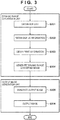
- Fig. 3 is a flowchart illustrating image processing according to this embodiment.
- the dynamic range conversion unit 201 obtains the RGB data of the HDR data.
- the HDR data according to this embodiment is stored in accordance with the above-described HLG method which defines the tone based on a relative luminance value.
- the tone is defined for each of R, G, and B elements based on a relative luminance value.
- the HLG method is employed in this embodiment, another method may be employed as long as the tone is defined relatively.
- the HDR data obtained in step S301 is also used in the display operation performed by the display apparatus 102 which is an HDR display.
- the dynamic range conversion unit 201 obtains the display information of the display apparatus 102.
- an image represented by HDR data is displayed on the display apparatus 102.
- the dynamic range conversion unit 201 obtains the display information storing the display state of the display apparatus 102 at that time via the display apparatus 102 or the PC 101. Also, in a case in which the display information is stored in the PC 101 at a suitable time in synchronization with the display, the dynamic range conversion unit 201 may obtain the display information from the PC 101.
- the display information will be obtained at the point of time in which the print application or the output apparatus 103 has been activated or reobtained at the timing at which the display setting has been changed on the side of the display apparatus 102. That is, it is sufficient as long as the display state of the display (the display apparatus 102) viewed by the user at the time of printing can be obtained.
- a single display is connected to the PC 101 in this embodiment, a plurality of displays may be simultaneously connected to a single PC and used in some cases. In a case in which extended display is performed by a plurality of displays (display performed across a plurality of displays), the display which is displaying the print preview of HDR data will be recognized and the display information of this play will be obtained.
- the user may select the display from which the display information is to be obtained or the display form which the display information is to be preferably obtained may be set in advance.
- dynamic range information and system gamma information of the display are obtained as display information.
- the dynamic range information includes a displayable maximum luminance value (maximum luminance value) when HDR data is displayed on the HDR display and the luminance value for displaying black on the display.
- maximum luminance value for example, 1,000 cd/m 2 and 0 cd/m 2 are obtained as the maximum luminance value and the luminance value of black, respectively, of the display.
- the dynamic range of the display changes when the display setting of the display apparatus 102 is changed, and the luminance dynamic range displayable by the display itself can change depending on the performance of the display.
- the dynamic range conversion unit 201 obtains the print information.
- the print information is information for specifying the dynamic range after the dynamic range conversion.
- print mode information is obtained as the print information, and whether an input to the output image generation unit 202 is SDR data of sRGB values will be specified based on the print mode information.
- a maximum luminance value of 100 cd/m 2 is specified as the luminance dynamic range after the conversion for the SDR data.
- the print information can be obtained by obtaining information which indicates the sheet type, and suffices to be information that can specify the reflection luminance which is specified from the sheet type. Another piece of information may be used as long as it is information from which the luminance dynamic range information at the time of printing can be obtained.
- a printed product may be irradiated with illumination of various kinds of illuminance depending on the observation environment. If the printed product is to be irradiated with illumination, the luminance dynamic range of a sheet will expand particularly due to the increase in the brightness of the whiteness of the paper. Hence, the reflection luminance of a sheet when the sheet is irradiated with illumination may be obtained as the luminance dynamic range information at the time of printing.
- step S304 the dynamic range conversion unit 201 generates, based on the display information obtained in step S302 and the print information obtained in step S303, image data obtained by converting the luminance dynamic range from the HDR data. That is, in this embodiment, dynamic range conversion processing is performed to convert a luminance dynamic range which has been obtained from the display information and has the maximum luminance value of 1,000 cd/m 2 based the obtained display information into a luminance dynamic range which has been obtained from the print information and has the maximum luminance value of 100 cd/m 2 . As described above, the luminance dynamic range after the dynamic range conversion becomes a luminance dynamic range expressed by the absolute luminance value specified by the print information.
- Hybrid Log Gamma (HLG) and Perceptual Quantization (PQ) are defined as two image transfer functions of HDR data in, for example, Recommendation ITU-R (International Telecommunication Union Radiocommunication Sector) BT.2100.
- the HDR data according to this embodiment is data converted by a transfer function OETF of the HLG method described above.
- EOTF an inverse function of OETF
- E' is an HLG method signal
- x is a signal normalized into a range between 0 and 1.
- ⁇ is a variable for a user gain
- Ys is a normalized luminance value
- E is a linear optical signal normalized into a range between 0 and 1.
- the dynamic range conversion unit 201 sets the data obtained from the OOTF processing as data whose maximum luminance value is 1,000 cd/m 2 , and performs dynamic range conversion processing to convert this data into data whose luminance dynamic range has a maximum luminance value of 100 cd/m 2 corresponding to the value obtained from the print information.
- the dynamic range conversion unit 201 performs the luminance dynamic range conversion to convert data of the converted luminance value Y into a luminance value Y' based on a conversion curve indicated by a solid line in a graph (the abscissa indicates an input luminance value and the ordinate indicates an output luminance value) shown in Fig. 4A .
- a short dashed line shown in Fig. 4A indicates a state in which the input and the output are linear.
- linear conversion is performed from a dark portion to a portion of a specific luminance, and conversion by a Log characteristic is performed in a highlight portion.
- Fig. 4A As shown in Fig.
- Fig. 4A it is preferable to perform dynamic range compression processing to maintain the contrast of the image while reproducing the highlight region of the HDR data.
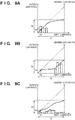
- Fig. 4B is a graph in which a dynamic range compression method similar to that of Fig. 4A has been employed, and shows the luminance relationship before and after the dynamic range conversion in a case in which the maximum luminance value of the display is 2,000 cd/m 2 .
- dynamic range conversion can be performed, in accordance with the displayable dynamic range of the display, based on the display information obtained in step S302 and the print information obtained in step S303.
- color gamut compression processing of converting the wide color gamut space of HDR data (for example, ITU-R BT.2020) into the color gamut of SDR data (for example, ITU-R BT.709) may be performed for the color gamut.
- the output image generation unit 202 generates output image data to be output to the printing unit 111.
- the output image generation unit 202 performs color conversion processing to convert the SDR data (RGB data), which was output in step S304, into device dependent RGB data.
- the output image generation unit 202 performs ink color resolution processing to convert the device dependent RGB data into ink color data, and performs tone correction processing to perform tone correction so that the ink color data will be linearly associated with the tone characteristic of the printing apparatus.
- the output image generation unit 202 performs halftone processing to convert the ink color data into ink dot ON/OFF information, masking data conversion processing which generates binary data to be printed in each print scan of the printhead, and the like.
- step S306 the output image generation unit 202 transmits the generated output image data to the printing unit 111, and an image is subsequently output on a print medium.
- HDR data of the HLG method is displayed differently depending on the performance of the display apparatus 102.
- the display information of the display apparatus 102 viewed by the user and the print information of the output apparatus 103 can be used at the time of printing of the HDR data of the HLG method so that dynamic range conversion corresponding to the display state of the display can be performed.
- a print output corresponding to the display of each of the plurality of the display apparatuses 102 with different performances can be obtained.
- HDR data (RGB data) obtained in step S301 of Fig. 3 is recorded in accordance with the PQ method which defines the tone in an absolute luminance value described above.
- PQ method which defines the tone in an absolute luminance value described above.
- a dynamic range conversion unit 201 obtains, as display information, the dynamic range information of a display and a luminance dynamic range conversion method.
- the description of the dynamic range information of the display is similar to that of the first embodiment.
- the luminance dynamic range conversion method is information related to the method of converting the luminance dynamic range of the PQ method defined by the maximum luminance value of 10,000 cd/m 2 into the luminance dynamic range of the display. This information suffices to be information that allows conversion to be executed in the process of step S304, and may be a conversion method name if the conversion is to be performed by a known method or may be information of a path in which a conversion module (for example, a conversion curve to be described later) is stored.
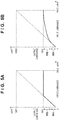
- Figs. 5A and 5B are graphs showing two kinds of conversion curves for luminance dynamic range conversion of a display.
- Fig. 5A shows a conversion method in which every data of a high luminance portion whose value is higher than 1,000 cd/m 2 and cannot be displayed on the display included in the HDR is displayed as 1,000 cd/m 2 .
- Fig. 5B shows a method similar to Figs. 4A and 4B in which data of a dark portion to a specific luminance portion is converted linearly and a highlight portion is converted by a Log characteristic.
- the HDR data is of the PQ method, although the conversion of Fig. 5A and the conversion of Fig.
- step S303 The print information obtainment process of step S303 is similar to that according to the first embodiment.
- step S304 the dynamic range conversion unit 201 generates, based on the display information obtained in step S302 and the print information obtained in step S303, data in which the luminance dynamic range has been converted from that of the HDR data.
- the dynamic range conversion unit 201 performs dynamic range conversion processing to convert information of a luminance dynamic range of the HDR data which has a maximum luminance value of 10,000 cd/m 2 into a luminance dynamic range obtained from the print information which has a maximum luminance value of 100 cd/m 2 .
- the HDR data according to this embodiment is data converted by a transfer function (an inverse function of EOTF) according to the PQ method described above.
- L B is 0.
- E' is a PQ method signal
- x is a signal normalized into a range between 0 and 1.
- the dynamic range conversion unit 201 sets the data converted from the EOTF processing as data whose maximum luminance value is 10,000 cd/m 2 , and performs dynamic range conversion processing to convert this data into data whose luminance dynamic range has a maximum luminance value of 100 cd/m 2 .
- the dynamic range conversion unit 201 converts RGB data obtained by the EOTF processing into data of a luminance value Y and color differences CbCr by equations (3), (4), and (5). Subsequently, the dynamic range conversion unit 201 performs conversion on the data of the converted luminance value Y by the conversion curve shown in Fig. 5A , and further performs conversion by the conversion curve shown in Fig.
- steps S305 and S306 are similar to those according to the first embodiment.
- the highlight portion of the data will be displayed differently depending on the performance of a display apparatus 102.
- the display information of the display apparatus 102 viewed by the user and the print information of an output apparatus 103 can be used at the time of printing of the HDR data of the PQ method so that dynamic range conversion corresponding to the display state of the display can be performed.
- a print output corresponding to the display of each of the plurality of the display apparatuses 102 with different performances can be obtained.
- This embodiment will describe a case in which HDR data of the PQ method is input and undergoes luminance dynamic range conversion on the side of a display apparatus 102 to be displayed on an SDR display.
- the display apparatus 102 is an SDR display.
- HDR data of the PQ method is obtained in step S301 of Fig. 3 .
- step S302 in a manner similar to the second embodiment, the dynamic range information and the luminance dynamic range conversion method of the display are obtained. Since the display apparatus 102 is an SDR display in this embodiment, 100 cd/m 2 and 0 cd/m 2 cm are obtained as a maximum luminance value and a luminance value of black, respectively, of the display. A description of the obtainment of the luminance dynamic range conversion method is similar to that according to the second embodiment.
- Fig. 6 is a graph showing a conversion curve of the luminance dynamic range conversion of the display according to this embodiment.
- Fig. 6 corresponds to a state in which the maximum luminance value of the luminance dynamic range of the display of Fig. 5B has been set to 100 cd/m 2 .
- luminance dynamic range conversion as shown in Fig. 6 will be performed in this embodiment, the dynamic range conversion method will change depending on the manufacturer or the model of the display as indicated by conversion curves 601 and 602.
- step S303 The obtainment of print information of step S303 is performed in a manner similar to that according to the first embodiment.
- a dynamic range conversion unit 201 generates, based on the display information obtained in step S302 and the print information obtained in step S303, image data obtained by converting the luminance dynamic range of the HDR data.
- the dynamic range conversion unit 201 performs dynamic range conversion processing to convert the information of the luminance dynamic range held by the HDR data into data whose luminance dynamic range has a maximum luminance value of 100 cd/m 2 corresponding to the value obtained from the print information.
- HDR data is converted into information corresponding to the luminance signal level of the display.
- dynamic range conversion processing is performed on the converted data to convert the luminance dynamic range into that corresponding to the luminance dynamic range whose maximum luminance value is 100 cd/m 2 obtained from the print information.
- the post-conversion luminance dynamic range of the display side and that of the printing side are equally 100 cd/m 2 .
- luminance dynamic range conversion is performed on the data of a converted luminance value Y by using the conversion curve shown in Fig. 6 , and the converted luminance and the color difference components are combined to perform conversion into RGB data of SDR by equations (6), (7), and (8).
- steps S305 and S306 are similar to those of the first embodiment.
- the display may differ depending on the fact that the luminance dynamic range conversion method will differ depending on the display apparatus 102.
- dynamic range conversion corresponding to the display state of the display can be performed.
- a print output corresponding to the display of each of the plurality of the SDR displays with different performances can be obtained.
- a dynamic range conversion unit 201 obtains, as display information, luminance dynamic range information of a display and data which has been converted into the luminance signal level of the display and in which the tone is defined by an absolute luminance value. That is, in a case in which HDR data of the HLG method is to be obtained, the RGB data which has undergone OOTF processing according to the first embodiment will be obtained. Also, in a case in which HDR data of the PQ method is to be obtained, RGB data that has been obtained by using the conversion curve of Fig. 5A to perform conversion on RGB data which has undergone the EOTF processing according to the second embodiment will be obtained.
- Data obtained by performing OETF processing (an inverse function of the EOTF) according to the PQ method on these data may also be obtained.
- These data can be generated by a display controller 114 in an image processing process of the display processing in a display apparatus 102, and be generated in the display apparatus 102 or in an apparatus outside the display apparatus 102 such as a PC 101 or the like.
- These data are stored in, for example, a storage unit of the display apparatus 102 or a storage unit of the apparatus outside the display apparatus 102 such as the PC 101 or the like.
- Data corresponding to the display state of the display at the point of time when the user has pressed a print button can be obtained from the storage unit.
- step S303 The print information obtainment process of step S303 is similar to that according to the first embodiment.
- step S304 the dynamic range conversion unit 201 generates, based on the display information obtained in step S302 and the print information obtained in step S303, image data in which the luminance dynamic range has been converted from that of the HDR data.
- the dynamic range conversion unit 201 will use the conversion curve of Fig. 4A to perform, based on the display information, luminance dynamic range conversion as described above on the HDR data obtained in step S301.
- the dynamic range conversion unit 201 will convert the information of the luminance dynamic range held by the data in which the maximum luminance value is 1,000 cd/m 2 into data whose luminance dynamic range has a maximum luminance value of 100 cd/m 2 corresponding to the value obtained from the print information.
- steps S305 and S306 are the similar to those of the first embodiment.
- the luminance dynamic range conversion may also be performed by using ICtCp.
- ICtCp is a color space which has a high dynamic range so as to target a wide color gamut signal.
- I be a luminance component
- CtCp be color difference components.
- the luminance component I is information which takes human vision characteristics in a wide luminance range into consideration.
- using the ICtCp color spaces allows luminance dynamic range conversion to be performed by taking the human vision characteristics into consideration.
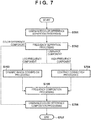
- the dynamic range conversion processing may be performed in accordance with the processing shown in the flowcharts of Figs. 7 and 8 .
- step S701 of Fig. 7 the dynamic range conversion unit 201 separates the RGB data obtained from the OOTF processing by equations (3), (4), and (5) into a luminance component and color difference components.
- the dynamic range conversion unit 201 performs processing to separate a low-frequency component and a high-frequency component of the data converted into the luminance component. This is because processing is changed between the low-frequency components and the high-frequency components based on the Retinex theory.
- the Retinex theory is a theory that models how the human brain perceives light and color. According to this theory, the intensity of light which enters the eye can be represented by a product of the reflectance of an object and illumination light illuminating the object, and the brightness and the color felt by a person depends more on the relative amount of change from the surroundings than an absolute optical amount.
- the absolute optical amount is the illumination light illuminating the object
- the relative amount of change is the reflectance of the object.
- the dynamic range conversion unit 201 extracts the low-frequency component of the image data as an illumination light component illuminating the object.
- a low pass filter is applied to create the low-frequency component.
- a spatial filter may be applied or a target frequency component may be temporarily converted into a spatial frequency by FFT and turned back into the frequency component by IFFT after undergoing filter processing.
- the frequency to be the target may be determined, in consideration of the human vision characteristics, based on the sheet size of the sheet on which the printed product is to be observed or an observation distance.
- a high pass filter which is the opposite of the low pass filter may be applied or the obtained low-frequency component may be subtracted from the original image.
- step S703 the dynamic range conversion unit 201 performs dynamic range conversion processing on the low-frequency component based on the input luminance dynamic range information and the output luminance dynamic range information.
- the processing of step S703 will be described in detail later with reference to Fig. 8 .
- step S704 the dynamic range conversion unit 201 performs contrast correction processing on the high-frequency component.
- the contrast correction processing is processing in which an obtained image is multiplied by a coefficient k.
- k approximately 1.
- a value equal to 1 or more is set as the coefficient k.
- step S705 the dynamic range conversion unit 201 combines the image data in which the dynamic range conversion has been performed on the low-frequency component and the image data in which contrast correction has been performed on the high-frequency component. As a result, the image data is compressed into a predetermined dynamic range, and a luminance image with a corrected contrast is obtained.
- step S706 the dynamic range conversion unit 201 combines the luminance component and the color difference component to perform conversion into RGB data by equations (6), (7), and (8). After the process of step S706, the processing of Fig. 7 ends.
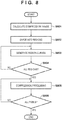
- step S703 The dynamic range conversion processing of step S703 will be described by using the flowchart of Fig. 8 .
- step S801 the dynamic range conversion unit 201 calculates a compression range.
- dynamic range conversion processing is performed to convert the luminance dynamic range which has been obtained from the display information and has a maximum luminance value of 1,000 cd/m 2 into the luminance dynamic range which has been obtained from the print information and has a maximum luminance value of 100 cd/m 2 .
- the dynamic range conversion unit 201 obtains an exposure luminance value Ya from the metadata of HDR data. This is the point where the user has set the exposure during an image capturing operation. Assume that the exposure luminance value Ya is 18 cd/m 2 in this embodiment.
- the dynamic range conversion unit 201 divides the image of the HDR data into regions.
- the region division of the image may be performed by dividing the image into predetermined rectangular size regions or by creating groups of similar luminance pixels based on the information of the luminance data. In the latter case, it is possible to restore the contrast of a specific luminance range that has undergone region division, and an image with better contrast can be obtained.
- Figs. 9A, 9B, and 9C are graphs each showing an example of a conversion curve.
- Fig. 9A is a graph representing the conversion curve of a given region.
- the abscissa indicates an input luminance value
- the ordinate indicates an output luminance value
- the thick line indicates the conversion curve.
- the bar graph shows the luminance distribution of the region, and the bars correspond to the degrees of a predetermined luminance range (corresponding to the ordinate on the right).
- Di denotes a pre-conversion luminance dynamic range
- Do denotes a post-conversion luminance dynamic range.
- the slope is 1, that is, 45°
- the input luminance value and the output luminance value will match, and image change will not occur in this portion. That is, the pre-conversion contrast of the dynamic range will be maintained.
- the post-conversion contrast degrades compared to the pre-conversion contrast.
- the contrast needs to be maintained to obtain a suitable post-conversion image, and it is preferable to set the slope to 1. Since a low-frequency component is being handled in this case, conversion needs to be performed, as much as possible, to set the slope to 1 to maintain the contrast of the low-frequency component.
- Fig. 9B represents the conversion curve of another region, but the luminance distribution is skewed toward the high-luminance side.
- a slope close to 1 is assigned to a high-degree luminance group in accordance with the degrees of the distribution.
- Fig. 9C represents a conversion curve of a region in which the luminance is distributed uniformly. In this case, the slope cannot be assigned to 1 even if a high-degree luminance group is present. This is because assigning a slope of 1 to a specific luminance group will cause the slope of another luminance group to be set closer to 0 due to the narrowness of the post-conversion luminance dynamic range Do.
- Figs. 9A to 9C representing different regions of the image have a common portion.
- This common portion is, for example, the exposure luminance value Ya obtained in step S801, and each conversion curve is created so that the luminance value after the conversion will constantly be a predetermined value Ya'.
- step S804 the dynamic range conversion unit 201 determines whether a conversion curve has been created for every divided region. If it is determined that the conversion curve has not been created for every divided region, the processing is repeated from step S803. Otherwise, the process advances to step S805.
- step S805 the dynamic range conversion unit 201 uses each created conversion curve to perform dynamic range compression procession on each pixel.
- the processing is performed in consideration of the information of the surrounding regions so as not to create locations where the tone becomes discontinuous between regions. More specifically, a window of the same degree as the region can be assigned so that weighting can be performed based on the area included in the window and the dynamic range compression processing can be performed based on this ratio. Also, since a simple area ratio can cause an image defect such as a halo to be generated on the boundary, the weight may be changed based on the average luminance value of the target region. That is, an image defect can be suppressed by reducing the weight compared to the target pixel in accordance with the increase in the variation of the average luminance values of the respective surrounding regions.
- step S806 the dynamic range conversion unit 201 determines whether the processing of step S805 has been performed on all of the pixels. If it is determined that the processing has not been performed on all of the pixels, the processing is repeated from step S805. Otherwise, the processing of Fig. 10 ends.
- Such cases may be, for example, a case in which the display information cannot be obtained from the display apparatus 102, a case in which the HDR data is directly input to the output apparatus 103 which does not have a display function, or the like.
- the processing performed in such cases is shown in Fig. 10 .
- determination as to whether the display information can be obtained is performed after the process of step S301. If it is determined that the display information cannot be obtained, the process of step S302 is skipped, and the image data is generated by luminance dynamic range conversion by using the HDR data and the print information in the process of step S304 following the process of step S303.
- the luminance dynamic range defined by the relative value held by the data is made to relatively correspond to the luminance dynamic range of the output apparatus 103.
- the conversion curves shown in Figs. 4A and 4B or the like will be used to convert the luminance dynamic range, of the data, which is defined by an absolute value into the luminance dynamic range at the time of printing. In this manner, the printing output can be adaptively changed in accordance with the presence/absence of the obtainment of the display information from the display apparatus 102.
- the user can select, via the UI, whether the luminance dynamic range compression is to be performed by using the display information or is to be performed without using the display information.
- the intention of the user can be reflected by allowing the user to select whether the print output is a print output corresponding to the display of the display apparatus 102 or a print output based on HDR data.
- the embodiments showed an example in which HDR data in compliance with the BT.2100 standard is to be displayed and printed.
- the present invention is not limited to the BT.2100 standard.
- Processing which is in compliance with another standard may be performed or only the transfer by OETF and EOTF may be performed.
- the HLG method and the PQ method have been exemplified as the transfer functions
- another method may be used as long as a transfer function that processes the HDR data by defining the tone by the relative luminance value or the absolute luminance value is used.
- the transfer functions and system gamma represented by equations (1) and (2) will be of a form that complies with the corresponding standard.
- a piece of conversion information unique to the display such as a gamma value of gamma conversion processing or the like may be obtained as the display information.
- Figs. 4A and 4B , 5A and 5B , and 6 were exemplified as luminance dynamic range conversion methods according to the embodiments, the present invention is not limited to these methods. Any kind of method can be used as long as it is a method that performs conversion of the luminance dynamic range.
- the input/output luminance dynamic ranges of the dynamic range conversion processing are not limited to the luminance dynamic ranges (1,000 cd/m 2 and the like) exemplified in each embodiment.
- the display apparatus 102 according to the embodiments may be an apparatus of any form, and is not limited to the display as long as it is an apparatus that can display information such as a panel or a touch panel attached to a smartphone or an apparatus.
- Embodiments) of the present invention can also be realized by a computer of a system or apparatus that reads out and executes computer executable instructions (e.g., one or more programs) recorded on a storage medium (which may also be referred to more fully as a 'non-transitory computer-readable storage medium') to perform the functions of one or more of the above-described embodiments) and/or that includes one or more circuits (e.g., application specific integrated circuit (ASIC)) for performing the functions of one or more of the above-described embodiments), and by a method performed by the computer of the system or apparatus by, for example, reading out and executing the computer executable instructions from the storage medium to perform the functions of one or more of the above-described embodiment(s) and/or controlling the one or more circuits to perform the functions of one or more of the above-described embodiments).
- computer executable instructions e.g., one or more programs
- a storage medium which may also be referred to more fully as a 'non
- the computer may comprise one or more processors (e.g., central processing unit (CPU), micro processing unit (MPU)) and may include a network of separate computers or separate processors to read out and execute the computer executable instructions.
- the computer executable instructions may be provided to the computer, for example, from a network or the storage medium.
- the storage medium may include, for example, one or more of a hard disk, a random-access memory (RAM), a read only memory (ROM), a storage of distributed computing systems, an optical disk (such as a compact disc (CD), digital versatile disc (DVD), or Blu-ray Disc (BD)TM), a flash memory device, a memory card, and the like.
- An image processing apparatus (103) comprises: first obtainment means configured to obtain HDR data which represents a high-dynamic range (HDR) image; second obtainment means configured to obtain print information to perform printing based on the HDR data obtained by the first obtainment means; third obtainment means configured to obtain display information of a display apparatus (102) which is to perform display based on the HDR data; and conversion means configured to convert, based on the display information obtained by the third obtainment means, a dynamic range of luminance of the HDR data obtained by the first obtainment means into a dynamic range by which printing is to be performed based on the print information obtained by the second obtainment means.
- HDR data which represents a high-dynamic range (HDR) image
- second obtainment means configured to obtain print information to perform printing based on the HDR data obtained by the first obtainment means
- third obtainment means configured to obtain display information of a display apparatus (102) which is to perform display based on the HDR data
- conversion means configured to convert, based on the display information obtained by the third obtainment means, a
Landscapes
- Engineering & Computer Science (AREA)
- Theoretical Computer Science (AREA)
- Multimedia (AREA)
- Signal Processing (AREA)
- Physics & Mathematics (AREA)
- General Physics & Mathematics (AREA)
- General Engineering & Computer Science (AREA)
- Human Computer Interaction (AREA)
- Computer Vision & Pattern Recognition (AREA)
- Quality & Reliability (AREA)
- Image Processing (AREA)
- Facsimile Image Signal Circuits (AREA)
Applications Claiming Priority (1)
| Application Number | Priority Date | Filing Date | Title |
|---|---|---|---|
| JP2020015535A JP7431595B2 (ja) | 2020-01-31 | 2020-01-31 | 画像処理装置、画像処理方法およびプログラム |
Publications (1)
| Publication Number | Publication Date |
|---|---|
| EP3860104A1 true EP3860104A1 (en) | 2021-08-04 |
Family
ID=74418212
Family Applications (1)
| Application Number | Title | Priority Date | Filing Date |
|---|---|---|---|
| EP21154213.9A Pending EP3860104A1 (en) | 2020-01-31 | 2021-01-29 | Image processing apparatus, image processing method, program, and non-transitory computer-readable storage medium storing program |
Country Status (5)
| Country | Link |
|---|---|
| US (1) | US12067304B2 (enExample) |
| EP (1) | EP3860104A1 (enExample) |
| JP (1) | JP7431595B2 (enExample) |
| KR (1) | KR20210098377A (enExample) |
| CN (1) | CN113205460B (enExample) |
Families Citing this family (4)
| Publication number | Priority date | Publication date | Assignee | Title |
|---|---|---|---|---|
| US20240078648A1 (en) * | 2022-09-06 | 2024-03-07 | Apple Inc. | Tone Mapping for Preserving Contrast of Fine Features in an Image |
| CN115293994B (zh) * | 2022-09-30 | 2022-12-16 | 腾讯科技(深圳)有限公司 | 图像处理方法、装置、计算机设备和存储介质 |
| JP2024098411A (ja) * | 2023-01-10 | 2024-07-23 | キヤノン株式会社 | 画像処理装置および画像処理方法 |
| EP4415343A1 (en) | 2023-02-08 | 2024-08-14 | Koninklijke Philips N.V. | Hdr out of gamut adjusted tone mapping |
Citations (4)
| Publication number | Priority date | Publication date | Assignee | Title |
|---|---|---|---|---|
| US20100053376A1 (en) * | 2008-09-01 | 2010-03-04 | Canon Kabushiki Kaisha | Image processing apparatus and method |
| WO2018092711A1 (ja) | 2016-11-17 | 2018-05-24 | パナソニックIpマネジメント株式会社 | 画像処理装置、画像処理方法、およびプログラム |
| EP3544280A1 (en) * | 2016-11-17 | 2019-09-25 | Panasonic Intellectual Property Management Co., Ltd. | Image processing device, image processing method, and program |
| US20200007717A1 (en) * | 2018-06-29 | 2020-01-02 | Canon Kabushiki Kaisha | Image processing apparatus, image processing method, and non-transitory computer-readable storage medium |
Family Cites Families (38)
| Publication number | Priority date | Publication date | Assignee | Title |
|---|---|---|---|---|
| US5012333A (en) * | 1989-01-05 | 1991-04-30 | Eastman Kodak Company | Interactive dynamic range adjustment system for printing digital images |
| JP2002016816A (ja) * | 2000-06-29 | 2002-01-18 | Seiko Epson Corp | 色補正方法および色補正装置 |
| US7941750B2 (en) * | 2001-10-11 | 2011-05-10 | Hewlett-Packard Development Company, L.P. | Method and system for defining separate print quality regions within a print job |
| WO2003061266A2 (en) | 2002-01-15 | 2003-07-24 | Yissum Research Development Company Of The Hebrew University Of Jerusalem | System and method for compressing the dynamic range of an image |
| US7672528B2 (en) | 2003-06-26 | 2010-03-02 | Eastman Kodak Company | Method of processing an image to form an image pyramid |
| US8218625B2 (en) | 2004-04-23 | 2012-07-10 | Dolby Laboratories Licensing Corporation | Encoding, decoding and representing high dynamic range images |
| US7426312B2 (en) | 2005-07-05 | 2008-09-16 | Xerox Corporation | Contrast enhancement of images |
| KR100739731B1 (ko) * | 2005-09-06 | 2007-07-13 | 삼성전자주식회사 | 표시된 화상의 인쇄를 위한 화상처리 방법 및 장치 |
| US7783121B1 (en) | 2005-11-29 | 2010-08-24 | Adobe Systems Incorporated | Method and apparatus for applying a filter to an image with a large range of pixel values |
| WO2008064349A1 (en) | 2006-11-22 | 2008-05-29 | Nik Software, Inc. | Method for dynamic range editing |
| US9830691B2 (en) | 2007-08-03 | 2017-11-28 | The University Of Akron | Method for real-time implementable local tone mapping for high dynamic range images |
| JP5489649B2 (ja) * | 2009-10-29 | 2014-05-14 | キヤノン株式会社 | 画像処理装置及び画像処理方法 |
| US9230312B2 (en) | 2010-01-27 | 2016-01-05 | Adobe Systems Incorporated | Methods and apparatus for performing tone mapping on high dynamic range images |
| US20110273731A1 (en) * | 2010-05-10 | 2011-11-10 | Canon Kabushiki Kaisha | Printer with attention based image customization |
| US9129388B2 (en) | 2012-11-21 | 2015-09-08 | Apple Inc. | Global approximation to spatially varying tone mapping operators |
| US9852499B2 (en) | 2013-12-13 | 2017-12-26 | Konica Minolta Laboratory U.S.A., Inc. | Automatic selection of optimum algorithms for high dynamic range image processing based on scene classification |
| CN105469375B (zh) | 2014-08-28 | 2021-09-07 | 北京三星通信技术研究有限公司 | 处理高动态范围全景图的方法和装置 |
| US10089960B2 (en) * | 2015-06-05 | 2018-10-02 | Apple Inc. | Rendering and displaying HDR content according to a perceptual model |
| KR102488954B1 (ko) * | 2016-05-16 | 2023-01-16 | 엘지전자 주식회사 | 영상 처리 장치 및 그의 영상 처리 방법 |
| US11184596B2 (en) | 2016-07-27 | 2021-11-23 | Panasonic Intellectual Property Management Co., Ltd. | Image processing device, reproduction device, image processing method, and reproduction method |
| US9883112B1 (en) | 2016-09-22 | 2018-01-30 | Pinnacle Imaging Corporation | High dynamic range imaging |
| US10567777B2 (en) | 2017-03-16 | 2020-02-18 | Intel Corporation | Contrast optimization and local adaptation approach for high dynamic range compression |
| JP6789877B2 (ja) * | 2017-04-28 | 2020-11-25 | キヤノン株式会社 | 情報処理装置、画像処理システム、制御システム及び情報処理方法 |
| CN107277399B (zh) * | 2017-06-09 | 2020-10-20 | 深圳Tcl新技术有限公司 | 电视终端及hdr图像转为sdr的方法和计算机可读存储介质 |
| JP2019080156A (ja) * | 2017-10-24 | 2019-05-23 | キヤノン株式会社 | 画像処理方法および画像処理装置 |
| JP7073191B2 (ja) | 2018-05-25 | 2022-05-23 | キヤノン株式会社 | 画像処理装置、画像処理方法及びプログラム |
| JP7117915B2 (ja) | 2018-06-29 | 2022-08-15 | キヤノン株式会社 | 画像処理装置、制御方法、及びプログラム |
| JP7104575B2 (ja) | 2018-06-29 | 2022-07-21 | キヤノン株式会社 | 画像処理装置、制御方法、及びプログラム |
| JP7105737B2 (ja) | 2018-06-29 | 2022-07-25 | キヤノン株式会社 | 画像処理装置、画像処理方法、及びプログラム |
| JP7212466B2 (ja) | 2018-07-06 | 2023-01-25 | キヤノン株式会社 | 画像処理装置、画像処理方法、プログラム、記憶媒体 |
| JP7280670B2 (ja) * | 2018-07-06 | 2023-05-24 | キヤノン株式会社 | 画像処理装置、制御方法、及びプログラム |
| JP7278096B2 (ja) * | 2019-02-20 | 2023-05-19 | キヤノン株式会社 | 画像処理装置、画像処理方法、およびプログラム |
| JP7301551B2 (ja) | 2019-02-21 | 2023-07-03 | キヤノン株式会社 | 画像処理装置、画像処理方法、表示装置、制御方法、およびプログラム |
| JP7296745B2 (ja) | 2019-03-05 | 2023-06-23 | キヤノン株式会社 | 画像処理装置、画像処理方法、及びプログラム |
| JP6921886B2 (ja) | 2019-03-19 | 2021-08-18 | キヤノン株式会社 | 情報処理装置および情報処理方法 |
| JP7388025B2 (ja) | 2019-07-19 | 2023-11-29 | セイコーエプソン株式会社 | 補正値設定方法、記録方法、及び記録装置 |
| US11295423B2 (en) | 2019-11-25 | 2022-04-05 | Intel Corportation | Unsupervised training of neural network for high dynamic range image compression |
| JP7431596B2 (ja) | 2020-01-31 | 2024-02-15 | キヤノン株式会社 | 画像処理装置、画像処理方法およびプログラム |
-
2020
- 2020-01-31 JP JP2020015535A patent/JP7431595B2/ja active Active
-
2021
- 2021-01-29 KR KR1020210013002A patent/KR20210098377A/ko not_active Ceased
- 2021-01-29 US US17/161,862 patent/US12067304B2/en active Active
- 2021-01-29 EP EP21154213.9A patent/EP3860104A1/en active Pending
- 2021-01-29 CN CN202110135015.9A patent/CN113205460B/zh active Active
Patent Citations (4)
| Publication number | Priority date | Publication date | Assignee | Title |
|---|---|---|---|---|
| US20100053376A1 (en) * | 2008-09-01 | 2010-03-04 | Canon Kabushiki Kaisha | Image processing apparatus and method |
| WO2018092711A1 (ja) | 2016-11-17 | 2018-05-24 | パナソニックIpマネジメント株式会社 | 画像処理装置、画像処理方法、およびプログラム |
| EP3544280A1 (en) * | 2016-11-17 | 2019-09-25 | Panasonic Intellectual Property Management Co., Ltd. | Image processing device, image processing method, and program |
| US20200007717A1 (en) * | 2018-06-29 | 2020-01-02 | Canon Kabushiki Kaisha | Image processing apparatus, image processing method, and non-transitory computer-readable storage medium |
Also Published As
| Publication number | Publication date |
|---|---|
| KR20210098377A (ko) | 2021-08-10 |
| US12067304B2 (en) | 2024-08-20 |
| JP7431595B2 (ja) | 2024-02-15 |
| CN113205460A (zh) | 2021-08-03 |
| JP2021124766A (ja) | 2021-08-30 |
| CN113205460B (zh) | 2025-02-11 |
| US20210241055A1 (en) | 2021-08-05 |
Similar Documents
| Publication | Publication Date | Title |
|---|---|---|
| EP3860105B1 (en) | Image processing apparatus, image processing method, program, and non-transitory computer-readable storage medium storing program | |
| US12067304B2 (en) | Image processing apparatus, image processing method, and non-transitory computer-readable storage medium storing a program that performs dynamic range conversion based on obtained display information | |
| US11146738B2 (en) | Image processing apparatus, control method, and non-transitory computer-readable storage medium | |
| US11182883B2 (en) | Image processing apparatus, image processing method, and non-transitory computer-readable storage medium that output a second image of which brightness values of pixels are output brightness values based on relationship information and an input brightness value of a first image | |
| US11323576B2 (en) | Image processing apparatus, image processing method, and non-transitory computer-readable medium | |
| US10582087B2 (en) | Image processing apparatus, control method, and non-transitory computer-readable storage medium | |
| US10848644B2 (en) | Image processing apparatus, image processing method, and non-transitory computer-readable storage medium | |
| US11435961B2 (en) | Image processing apparatus, image processing method, control apparatus, control method, and storage medium that display converted image data whose maximum luminance has been set according to an obtained lighting luminance | |
| US20190364171A1 (en) | Image processing apparatus, image processing method, and storage medium | |
| US12198315B2 (en) | Information processing apparatus, information processing method, and storage medium for storing program in which a minimum luminance value of display luminance information is greater than that of print luminance information | |
| US8781242B2 (en) | Image processing apparatus, image processing method, and program | |
| US10861137B2 (en) | Image processing apparatus, image processing method, and storage medium | |
| US11368606B1 (en) | Image processing apparatus and non-transitory computer readable medium | |
| JP2019053711A (ja) | 画像処理装置、画像処理方法、およびプログラム |
Legal Events
| Date | Code | Title | Description |
|---|---|---|---|
| PUAI | Public reference made under article 153(3) epc to a published international application that has entered the european phase |
Free format text: ORIGINAL CODE: 0009012 |
|
| STAA | Information on the status of an ep patent application or granted ep patent |
Free format text: STATUS: THE APPLICATION HAS BEEN PUBLISHED |
|
| AK | Designated contracting states |
Kind code of ref document: A1 Designated state(s): AL AT BE BG CH CY CZ DE DK EE ES FI FR GB GR HR HU IE IS IT LI LT LU LV MC MK MT NL NO PL PT RO RS SE SI SK SM TR |
|
| STAA | Information on the status of an ep patent application or granted ep patent |
Free format text: STATUS: REQUEST FOR EXAMINATION WAS MADE |
|
| 17P | Request for examination filed |
Effective date: 20220204 |
|
| RBV | Designated contracting states (corrected) |
Designated state(s): AL AT BE BG CH CY CZ DE DK EE ES FI FR GB GR HR HU IE IS IT LI LT LU LV MC MK MT NL NO PL PT RO RS SE SI SK SM TR |
|
| STAA | Information on the status of an ep patent application or granted ep patent |
Free format text: STATUS: EXAMINATION IS IN PROGRESS |
|
| 17Q | First examination report despatched |
Effective date: 20240213 |