EP3859312A1 - Verfahren zur beurteilung der oberfläche eines gleitkörpers und vorrichtung zur beurteilung der oberfläche eines gleitkörpers - Google Patents
Verfahren zur beurteilung der oberfläche eines gleitkörpers und vorrichtung zur beurteilung der oberfläche eines gleitkörpers Download PDFInfo
- Publication number
- EP3859312A1 EP3859312A1 EP19865096.2A EP19865096A EP3859312A1 EP 3859312 A1 EP3859312 A1 EP 3859312A1 EP 19865096 A EP19865096 A EP 19865096A EP 3859312 A1 EP3859312 A1 EP 3859312A1
- Authority
- EP
- European Patent Office
- Prior art keywords
- sliding
- sliding body
- surface evaluation
- electromagnetic wave
- sliding portion
- Prior art date
- Legal status (The legal status is an assumption and is not a legal conclusion. Google has not performed a legal analysis and makes no representation as to the accuracy of the status listed.)
- Pending
Links
- 238000011156 evaluation Methods 0.000 title claims abstract description 32
- 230000008859 change Effects 0.000 claims abstract description 29
- 230000001678 irradiating effect Effects 0.000 claims abstract description 6
- XLYOFNOQVPJJNP-UHFFFAOYSA-N water Substances O XLYOFNOQVPJJNP-UHFFFAOYSA-N 0.000 claims description 15
- 239000000314 lubricant Substances 0.000 claims description 8
- 230000035515 penetration Effects 0.000 claims description 4
- 238000000034 method Methods 0.000 abstract description 12
- 230000002123 temporal effect Effects 0.000 abstract description 5
- HBMJWWWQQXIZIP-UHFFFAOYSA-N silicon carbide Chemical compound [Si+]#[C-] HBMJWWWQQXIZIP-UHFFFAOYSA-N 0.000 description 26
- 229910010271 silicon carbide Inorganic materials 0.000 description 26
- 238000012360 testing method Methods 0.000 description 22
- 239000000463 material Substances 0.000 description 15
- 230000009467 reduction Effects 0.000 description 13
- 230000007423 decrease Effects 0.000 description 9
- 239000000843 powder Substances 0.000 description 8
- 238000002474 experimental method Methods 0.000 description 7
- 239000011148 porous material Substances 0.000 description 7
- 230000008569 process Effects 0.000 description 7
- 239000000126 substance Substances 0.000 description 6
- 239000012530 fluid Substances 0.000 description 4
- 230000009471 action Effects 0.000 description 3
- 239000000919 ceramic Substances 0.000 description 3
- 230000002349 favourable effect Effects 0.000 description 3
- 230000007246 mechanism Effects 0.000 description 3
- 239000003921 oil Substances 0.000 description 3
- 230000009466 transformation Effects 0.000 description 3
- 238000005280 amorphization Methods 0.000 description 2
- 230000003247 decreasing effect Effects 0.000 description 2
- 239000011521 glass Substances 0.000 description 2
- 238000007789 sealing Methods 0.000 description 2
- 230000035945 sensitivity Effects 0.000 description 2
- 238000007792 addition Methods 0.000 description 1
- 230000002411 adverse Effects 0.000 description 1
- PNEYBMLMFCGWSK-UHFFFAOYSA-N aluminium oxide Inorganic materials [O-2].[O-2].[O-2].[Al+3].[Al+3] PNEYBMLMFCGWSK-UHFFFAOYSA-N 0.000 description 1
- 238000013459 approach Methods 0.000 description 1
- 229910052593 corundum Inorganic materials 0.000 description 1
- 239000013078 crystal Substances 0.000 description 1
- 230000000694 effects Effects 0.000 description 1
- 230000005284 excitation Effects 0.000 description 1
- 239000012847 fine chemical Substances 0.000 description 1
- ZZUFCTLCJUWOSV-UHFFFAOYSA-N furosemide Chemical compound C1=C(Cl)C(S(=O)(=O)N)=CC(C(O)=O)=C1NCC1=CC=CO1 ZZUFCTLCJUWOSV-UHFFFAOYSA-N 0.000 description 1
- 229910003465 moissanite Inorganic materials 0.000 description 1
- 238000007254 oxidation reaction Methods 0.000 description 1
- 230000000149 penetrating effect Effects 0.000 description 1
- 230000002093 peripheral effect Effects 0.000 description 1
- 239000011295 pitch Substances 0.000 description 1
- 239000008213 purified water Substances 0.000 description 1
- 239000002904 solvent Substances 0.000 description 1
- 238000010183 spectrum analysis Methods 0.000 description 1
- 239000002344 surface layer Substances 0.000 description 1
- 229910001845 yogo sapphire Inorganic materials 0.000 description 1
Images


Classifications
-
- G—PHYSICS
- G01—MEASURING; TESTING
- G01N—INVESTIGATING OR ANALYSING MATERIALS BY DETERMINING THEIR CHEMICAL OR PHYSICAL PROPERTIES
- G01N21/00—Investigating or analysing materials by the use of optical means, i.e. using sub-millimetre waves, infrared, visible or ultraviolet light
- G01N21/62—Systems in which the material investigated is excited whereby it emits light or causes a change in wavelength of the incident light
- G01N21/63—Systems in which the material investigated is excited whereby it emits light or causes a change in wavelength of the incident light optically excited
- G01N21/64—Fluorescence; Phosphorescence
- G01N21/645—Specially adapted constructive features of fluorimeters
- G01N21/6456—Spatial resolved fluorescence measurements; Imaging
- G01N21/6458—Fluorescence microscopy
-
- G—PHYSICS
- G01—MEASURING; TESTING
- G01N—INVESTIGATING OR ANALYSING MATERIALS BY DETERMINING THEIR CHEMICAL OR PHYSICAL PROPERTIES
- G01N21/00—Investigating or analysing materials by the use of optical means, i.e. using sub-millimetre waves, infrared, visible or ultraviolet light
- G01N21/62—Systems in which the material investigated is excited whereby it emits light or causes a change in wavelength of the incident light
- G01N21/63—Systems in which the material investigated is excited whereby it emits light or causes a change in wavelength of the incident light optically excited
- G01N21/64—Fluorescence; Phosphorescence
- G01N21/645—Specially adapted constructive features of fluorimeters
- G01N21/6456—Spatial resolved fluorescence measurements; Imaging
- G01N2021/646—Detecting fluorescent inhomogeneities at a position, e.g. for detecting defects
-
- G—PHYSICS
- G01—MEASURING; TESTING
- G01N—INVESTIGATING OR ANALYSING MATERIALS BY DETERMINING THEIR CHEMICAL OR PHYSICAL PROPERTIES
- G01N21/00—Investigating or analysing materials by the use of optical means, i.e. using sub-millimetre waves, infrared, visible or ultraviolet light
- G01N21/62—Systems in which the material investigated is excited whereby it emits light or causes a change in wavelength of the incident light
- G01N21/63—Systems in which the material investigated is excited whereby it emits light or causes a change in wavelength of the incident light optically excited
- G01N21/64—Fluorescence; Phosphorescence
- G01N21/6489—Photoluminescence of semiconductors
-
- G—PHYSICS
- G01—MEASURING; TESTING
- G01N—INVESTIGATING OR ANALYSING MATERIALS BY DETERMINING THEIR CHEMICAL OR PHYSICAL PROPERTIES
- G01N2201/00—Features of devices classified in G01N21/00
- G01N2201/06—Illumination; Optics
- G01N2201/061—Sources
- G01N2201/06113—Coherent sources; lasers
Definitions
- the present invention relates to sliding body surface evaluation method and apparatus for observing a sliding portion of a sliding body.
- a sliding portion where separate members slide on each other to generate friction.
- a sliding body such as a rotating seal ring or a stationary seal ring forming an apparatus configured to seal a rotary shaft of a fluid machine, such as a mechanical seal
- a fluid machine such as a mechanical seal
- the sliding portion observation method includes an observation apparatus as described in Patent Citation 1.
- the observation apparatus of Patent Citation 1 includes a holding tool configured to hold a sliding body as a test piece and drive means configured to rotate a light-permeable sliding target body.
- the observation apparatus irradiates sliding surfaces of the sliding body and the sliding target body with light from a light source, receives light having reflected on the sliding surface and having penetrated the sliding target body by a digital camera, and obtains an image of the sliding surface.
- Patent Citation 1 Japanese Patent No. 5037444 (page 7, FIG. 2 )
- the sliding target body is light-permeable glass.
- the image of the sliding surface of the rotatably-driven sliding body can be obtained, and recessed and raised portions of the sliding surface and an oil film during sliding can be visually observed.
- an event influencing a decrease in the coefficient of friction of the sliding portion is not limited to the surface shape of the sliding surface and an interposed oil film state and a transformed portion of a base material due to friction of the sliding portion also provides influence.
- the technique of Patent Citation 1 is not intended to observe a temporal change in the transformed portion of the sliding portion, and fails to perform such observation.
- the present invention has been made in view of such a problem, and is intended to provide sliding body surface evaluation method and apparatus configured so that a temporal change in a transformed portion at a sliding portion of a sliding body can be observed.
- a sliding body surface evaluation method includes: a first step of irradiating, with an electromagnetic wave, a sliding portion of a sliding body sliding on a sliding target body; a second step of detecting light emitted from the sliding portion irradiated with the electromagnetic wave; and a third step of deriving a change in a light emission state of the sliding portion.
- the light emitted from the sliding portion is detected, and the change in the light emission state is derived.
- a transformed portion chemically and geometrically transformed from a surface of the sliding body due to friction can be visualized, and a temporal change in such a transformed portion can be observed.
- the first step includes a step of scanning the entire surface of the sliding portion with the electromagnetic wave. According to this preferable configuration, the change in the light emission state is observed across the entire surface of the sliding portion, and therefore, e.g., a region of the sliding portion where friction reduction is likely to occur can be evaluated.
- the first step includes a step of irradiating the sliding portion with the electromagnetic wave while rotatably driving the sliding body. According to this preferable configuration, the sliding body is rotated so that the entire surface of the sliding portion can be easily observed.
- the first step includes a step of deriving a light emission region of the sliding portion. According to this preferable configuration, the course of decreasing the coefficient of friction of the sliding portion can be observed based on a change in the light emission region.
- the third step includes a step of excluding a region with a luminance of equal to or higher than a predetermined luminance from the light emission region. According to this preferable configuration, influence of wear powder filling pores of a surface of the sliding portion can be excluded, and a substantially-formed transformed portion region can be accurately evaluated.
- the first step includes a step of performing scanning with the electromagnetic wave by a confocal scanning microscope.
- the confocal scanning microscope can detect the low-luminance sliding portion, particularly light emission from the transformed portion.
- the first step includes a step of finely moving the focal point of the confocal scanning microscope in a depth direction of the sliding portion.
- the sliding portion can be three-dimensionally analyzed, and a transformed portion light emission area can be observed according to, e.g., the thickness or depth of the formed transformed portion.
- a sliding body surface evaluation apparatus includes: a holding member configured to hold a sliding body; drive means configured to rotatably drive the sliding body; an irradiation device configured to irradiate a sliding portion of the sliding body with an electromagnetic wave; a detector configured to detect light emitted from the sliding portion irradiated with the electromagnetic wave; and an arithmetic device configured to derive a change in a light emission state of the sliding portion from the light detected by the detector.
- the light emitted from the sliding portion is detected, and the change in the light emission state is derived.
- a transformed portion chemically and geometrically transformed from a surface of the sliding body due to friction can be visualized, and a temporal change in such a transformed portion can be observed.
- the sliding body surface evaluation apparatus further includes a second holding member capable of holding a sliding target body sliding on the sliding body, the sliding target body allowing penetration of the electromagnetic wave and the light and the irradiation device being arranged at a position at which the sliding portion of the sliding body is irradiated with the electromagnetic wave through the sliding target body.
- the sliding portion of the sliding body can be irradiated with the electromagnetic wave through the sliding target body, and the light emitted from the sliding portion can be detected through the sliding target body.
- the course of changing the transformed portion of the sliding portion can be observed.
- the sliding body is polycrystal SiC
- the sliding target body is monocrystal SiC. According to this preferable configuration, it is configured such that the electromagnetic wave and the light penetrate the sliding target body and physical characteristics of the sliding body and the sliding target body approximate to each other. Thus, the course of changing the transformed portion of the surface of the sliding portion can be observed with favorable accuracy.
- water is, as a lubricant, supplied to between the sliding body and the sliding target body.
- the low-viscosity water is utilized as the lubricant for the sliding portion, and therefore, a running-in phenomenon progress status of the surface of the sliding portion can be observed with favorable accuracy.
- a phenomenon that due to initial sliding, the coefficient of friction of a sliding body rapidly decreases and becomes stable after the coefficient of friction of a sliding portion has temporarily increased, i.e., a so-called "running-in phenomenon,” has been known. It has been considered that in a running-in process, shear force, heat, pressure, etc. act on the sliding portion and a transformed portion formed due to a chemical and geometrical change in a surface of the sliding portion is dominant in friction reduction.
- a sliding body surface evaluation method and a sliding body surface evaluation apparatus according to a first embodiment of the present invention will be described with reference to FIGS. 1 to 7 .
- the inventor(s) has conducted an experiment to observe a surface of a sliding body.
- a surface evaluation apparatus hereinafter merely referred to as a test machine 30
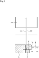
- a temperature-controllable ring-on-ring thrust friction wear test machine as illustrated in FIG. 1 was used for performing a test for sliding friction between end surfaces of silicon carbide (abbreviated as SiC) as ceramics.
- SiC silicon carbide
- a circular ring-shaped sliding body 3 made of polycrystal silicon carbide (hereinafter referred to as polycrystal SiC) and a circular ring-shaped sliding target body 4 made of monocrystal silicon carbide (hereinafter referred to as monocrystal SiC) were used as sliding bodies used as the test pieces.
- the polycrystal SiC forming the sliding body 3 has the same quality as those used for a rotating seal ring or a stationary seal ring of a mechanical seal used for, e.g., sealing of fluid equipment.
- the monocrystal SiC having hardness and friction coefficient characteristics equivalent to those of the polycrystal SiC but allowing, for penetration of later-described laser light 10 as excitation light, more light to penetrate the monocrystal SiC as compared to the polycrystal SiC was used.
- the sliding body 3 one with an outer diameter of 18 mm, an inner diameter of 8 mm, and a thickness of 8 mm was used.
- the sliding target body 4 one with an outer diameter of 16 mm, an inner diameter of 11 mm, and a thickness of 8 mm was used.
- the test machine 30 includes a housing 2 rotatably coupled to a base 1 and configured to hold the sliding body 3, and the sliding target body 4 is arranged above the sliding body 3 so as to contact the sliding body 3.
- the housing 2 has a discoid bottom portion 2a configured such that a through-hole 2b penetrating in an upper-lower direction is provided at a center portion, a cylindrical shaft portion 2c provided at a lower surface of the bottom portion 2a, and a cylindrical side portion 2d provided at an outer peripheral edge of the bottom portion 2a and extending upwardly.
- the housing 2 is rotatably coupled to the base 1 through a bearing 5 arranged at the outer periphery of the shaft portion 2c.
- the inside of the housing 2 houses water 8 with such a water level that at least opposing end surfaces of the sliding body 3 and the sliding target body 4 are immersed, and the water entering between these end surfaces functions as a lubricant in relative rotation sliding of the sliding body 3 and the sliding target body 4.
- the water 8 supplied to between the end surfaces of the sliding body 3 and the sliding target body 4 is purified water at 25°C, and circulates and is supplied at 60 ml/min.
- the sliding body 3 is held at an upper end opening of the through-hole 2b of the housing 2 in a state in which the end surface of the sliding body 3 faces up.
- the sliding target body 4 is arranged above the sliding body 3 so as to contact the sliding body 3 held in the housing 2.
- each of the sliding body 3 and the sliding target body 4 is held in a state in which a load is provided to between the sliding body 3 and the sliding target body 4 from above the sliding body 3 by a not-shown load motor.
- This load is measured by a not-shown load cell, and is equivalent to biasing force of elastic means such as a spring configured to cause the rotating seal ring and the stationary seal ring of the mechanical seal used for, e.g., sealing of the fluid equipment to approach each other.
- the sliding target body 4 is fixed to an upper end portion of a rotary shaft 6 inserted into the through-hole 2b of the housing 2, and the rotary shaft 6 is coupled to a rotary drive source 7 such as a motor and is rotatable by drive of the rotary drive source 7.
- a rotary drive source 7 such as a motor and is rotatable by drive of the rotary drive source 7.
- an annular seal 11 positioned on an outer diameter side of the rotary shaft 6 seals between the rotary shaft 6 and the through-hole 2b.
- the test machine 30 includes a confocal scanning microscope 16 (manufactured by Olympus Corporation).
- the confocal scanning microscope 16 has a light source 9 configured to emit the laser light 10, a field lens 18, a beam splitter 19, a detector 20, and a pinhole 12 configured to eliminate scattered light from fluorescence as light having entered the detector 20.
- the laser light 10 emitted from the light source 9 is reflected on the beam splitter 19 and passes through the field lens 18, and a sliding portion 3a of the sliding body 3 is irradiated with the laser light 10 through the sliding target body 4.
- the sliding portion 3a indicates a sliding portion 3a as a location where the sliding body 3 slides on the sliding target body 4, and as illustrated in FIG. 7 , means a surface layer portion of the sliding body 3 including a transformed portion 3p and an untransformed base material portion 3b.
- Fluorescence 17 as a target for observation with the laser light 10 and the laser light reflected on the observation target are collected again by the field lens 18 through the sliding target body 4.
- the reflected laser light is reflected on the beam splitter 19, and only the fluorescence 17 passes toward a detector 20 side. Scattered light is eliminated from the fluorescence 17 by the pinhole 12 before reaching the detector 20, and thereafter, the fluorescence 17 enters the detector 20. The incident fluorescence 17 is amplified in the detector 20.
- a filter configured to block the wavelength of the fluorescence emitted from the base material portion 3b is preferably provided between the beam splitter 19 and the pinhole 12.
- the beam splitter 19 is finely turned and driven by a not-shown drive mechanism so that the reflection angle thereof can be changed and an irradiation direction of the laser light 10 can be changed.
- a surface of the sliding portion 3a of the sliding body 3 can be scanned in a radial direction with the laser light 10.
- the incident light is converted into digital data so that a three-dimensional image of the observation target can be produced.
- the test machine 30 further includes housing rotation control means 23 configured to rotate and stop the housing at constant pitches.
- a servo motor 24 is used as the housing rotation control means 23.
- teeth of a gear may be provided at the outer periphery of the housing 2
- a ratchet mechanism may be provided on a base 1 side, and these teeth and the ratchet mechanism may be engaged with each other.
- Arithmetic analysis is performed for the image detected by the detector 20 in a not-shown arithmetic apparatus such as a personal computer, and in this manner, a fluorescence region of the sliding portion 3a, the ratio of the area of the fluorescence region to the entire surface of the sliding portion 3a, and luminance distribution can be evaluated.
- Friction force is converted using friction torque added to a test piece tool supported by the bearing.
- the load of the load motor providing the load to between the sliding body 3 and the sliding target body 4 was 32 N, 53 N, and 212 N.
- the rotational speed of the housing was 142 rpm, 284 rpm, 1420 rpm, and 2840 rpm.
- the initial roughness (hereinafter referred to as Ra) of the sliding body 3 before sliding was Ra ⁇ 0.1 and Ra ⁇ 0.01.
- the initial Ra of the sliding target body 4 before sliding was Ra ⁇ 0.01.
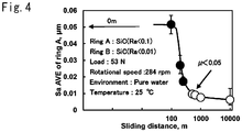
- FIG. 4 illustrates results of the arithmetic average height (Sa) of the sliding portion 3a of the sliding body 3. It was confirmed that a smooth sliding surface is rapidly formed in a running-in process and a nanometer-order change continues according to a sliding distance even after occurrence of friction reduction to form an ultra-smooth sliding surface.
- the present inventor(s) has found that the transformed portion chemically changed from SiC due to, e.g., amorphization shows fluorescence, and it has been found that a running-in process can be clarified by observation/evaluation of the transformed portion according to a fluorescence phenomenon. Detailed description will be made hereinafter.
- FIG. 6A illustrates an image of the surface of the sliding portion 3a captured by the confocal scanning microscope 16 when the sliding distance is 98 m, and a white portion indicates the fluorescence region.
- FIG. 6B illustrates the fluorescence region when the sliding distance is 200 m.
- the fluorescence region is the transformed portion 3p, and a black portion is the untransformed base material portion 3b. From FIGS. 6A, 6B , and 5 , it has been confirmed that Sa and the fluorescence region both show a significant change particularly in a range of 98 m to 200 m in which the coefficient of friction increases and the fluorescence region significantly increases.
- the wear powder filling the pores has a higher luminance than that of the transformed portion.
- the step of excluding a region with a luminance equal to or higher than a predetermined luminance from a light emission area is performed so that influence of the wear powder filling the pores of the surface of the sliding portion 3a can be excluded and the area of the formed transformed portion can be reliably evaluated.
- a nano interface having the transformed portion across a large portion and having a thickness of several nm was, unlike SiC of the base material, formed at any of the sliding surface (e.g., the sliding surface in the case of a sliding distance of 519 m) shortly after occurrence of friction reduction and the sliding surface (e.g., the sliding surface in the case of a sliding distance of 10 km) sufficiently slid after occurrence of friction reduction.
- the sliding surface e.g., the sliding surface in the case of a sliding distance of 10 km
- the sliding body surface evaluation method includes the first step of irradiating, between the sliding body 3 and the sliding target body 4 made of SiC, the sliding portion 3a of the sliding body 3 with the laser light 10, the second step of detecting the fluorescence as the light emitted from the transformed portion 3p irradiated with the laser light 10, and the third step of deriving a change in a light emission state of the sliding portion 3a.
- a running-in phenomenon progress status can be evaluated from the change in the light emission state in which a SiC plateau portion is formed, and a decrease in the coefficient of friction can be reliably evaluated.
- the entire surface of the sliding portion 3a is scanned with the laser light 10, and the light emission area is calculated across the entire surface of the sliding portion 3a.
- a region of the sliding portion 3a where friction reduction is likely to occur can be evaluated.
- a prominent "running-in phenomenon" in a specific region in the radial direction can be evaluated.
- the confocal scanning microscope is used for observation of the sliding portion 3a so that light emitted from the sliding portion 3a with a low luminance can be reliably detected.
- the water is supplied as the lubricant to between the sliding body 3 and the sliding target body 4.
- the low-viscosity water is utilized as the lubricant for the sliding portion, and therefore, the running-in phenomenon progress status of the surface of the sliding portion 3a can be observed with favorable accuracy.
- the test machine 30 may include a drive apparatus (not shown) capable of finely moving, in the upper-lower (Z-axis) direction, the height position of the field lens 18 of the confocal scanning microscope 16.
- a drive apparatus capable of finely moving, in the upper-lower (Z-axis) direction, the height position of the field lens 18 of the confocal scanning microscope 16.
- the focal point of the confocal scanning microscope 16 is finely moved in a depth direction of the sliding portion 3a so that the sliding portion 3a can be three-dimensionally analyzed and the thickness of the formed transformed portion 3p can be observed.
- the fluorescence region is observed for each depth so that a region where the transformed portion 3p is generated can be observed for each depth.
- the transformed portion 3p of the sliding portion 3a as described herein has a thickness of about several ⁇ m, and therefore, these types of observation are significant.
- the sliding body 3 one arranged on a lower side as the test piece observed with the confocal scanning microscope 16 has been described as the sliding body 3, and one arranged on an upper side as a sliding partner of the sliding body 3 has been described as the sliding target body 4.
- the observation target is not distinguished by phrases of the sliding body and the sliding target body, and may be a sliding portion of the sliding target body arranged on the upper side.
- a sliding body is a rod-shaped member 33 instead of a cylindrical member.
- a sliding portion of a sliding target body 4 is an observation target.
- FIGS. 9A and 9B a sliding body surface evaluation method and a sliding body surface evaluation apparatus according to a third embodiment will be described with reference to FIGS. 9A and 9B . Note that description of the same overlapping configurations as those of the above-described embodiments will be omitted.
- a sliding target body 40 is formed in a cylindrical shape from polycrystal SiC through which less laser light penetrates.
- the sliding target body 40 is detached, and a sliding portion 3a of the sliding body 3 is observed using a confocal scanning microscope 16 of a test machine 30.
- the sliding body 3 and the sliding target body 40 can be made of materials similar to those in the case of a rotating seal ring and a stationary seal ring of a mechanical seal to be actually used, and an accurate sliding portion observation result can be obtained.
- FIG. 9B is a variation of FIG. 9A , and a sliding target body 41 is a rod-shaped member instead of the cylindrical member.
- the sliding portion 3a of the sliding body 3 can be observed using the confocal scanning microscope 16 without the need for detaching the sliding target body 41.
- test machine utilized for the sliding body surface evaluation method is not limited to the above-described configuration of the test machine 30.
- the sliding target body may be made of another material allowing light penetration, such as glass, instead of the monocrystal SiC. In this case, those close to the sliding body in terms of physical characteristics are preferable.
- the light source configured to irradiate the sliding portion 3a with an electromagnetic wave may be, e.g., a lamp other than the laser light source, and is not limited to visible light.
- An electromagnetic wave of invisible light such as ultraviolet light or infrared light may be employed.
- those other than the above-described confocal scanning microscope may be used.
- the amorphous whose crystal structure has been transformed from the base material has been described as an example of the transformed portion 3p transformed from the base material.
- the transformed portion may be a portion whose material characteristics have been chemically, mechanically, or thermally transformed, and for example, includes a transformed portion due to oxidization.
- the sliding body 3 may be made of a material other than the ceramics, but ceramics such as SiC or Al 2 O 3 is preferable.
- the lubricant supplied to between the end surfaces of the sliding body 3 and the sliding target body 4 is not limited to the water, and for example, may be gas, a solvent, or oil.
- the water housed in the housing 2 is arranged only on the outer diameter side of the sliding body 3 and the sliding target body 4, but the present invention is not limited to above.
- the water may be arranged on an inner diameter side of the sliding body 3 and the sliding target body 4 or on both of the outer diameter side and the inner diameter side.
- different types of lubricants may be arranged on the outer diameter side and the inner diameter side.
- the change in the light emission state may be one or both of the light emission area and the luminance, and may be a light emission state other than the light emission area and the luminance.
Landscapes
- Health & Medical Sciences (AREA)
- Nuclear Medicine, Radiotherapy & Molecular Imaging (AREA)
- Physics & Mathematics (AREA)
- Life Sciences & Earth Sciences (AREA)
- Chemical & Material Sciences (AREA)
- Analytical Chemistry (AREA)
- Biochemistry (AREA)
- General Health & Medical Sciences (AREA)
- General Physics & Mathematics (AREA)
- Immunology (AREA)
- Pathology (AREA)
- Investigating, Analyzing Materials By Fluorescence Or Luminescence (AREA)
Applications Claiming Priority (2)
| Application Number | Priority Date | Filing Date | Title |
|---|---|---|---|
| JP2018184006 | 2018-09-28 | ||
| PCT/JP2019/037898 WO2020067306A1 (ja) | 2018-09-28 | 2019-09-26 | 摺動体の表面評価方法及び摺動体の表面評価装置 |
Publications (2)
| Publication Number | Publication Date |
|---|---|
| EP3859312A1 true EP3859312A1 (de) | 2021-08-04 |
| EP3859312A4 EP3859312A4 (de) | 2022-06-08 |
Family
ID=69953457
Family Applications (1)
| Application Number | Title | Priority Date | Filing Date |
|---|---|---|---|
| EP19865096.2A Pending EP3859312A4 (de) | 2018-09-28 | 2019-09-26 | Verfahren zur beurteilung der oberfläche eines gleitkörpers und vorrichtung zur beurteilung der oberfläche eines gleitkörpers |
Country Status (5)
| Country | Link |
|---|---|
| US (1) | US11719640B2 (de) |
| EP (1) | EP3859312A4 (de) |
| JP (1) | JP7383358B2 (de) |
| CN (1) | CN112740019A (de) |
| WO (1) | WO2020067306A1 (de) |
Family Cites Families (12)
| Publication number | Priority date | Publication date | Assignee | Title |
|---|---|---|---|---|
| JPS63314372A (ja) * | 1987-06-15 | 1988-12-22 | Hitachi Ltd | 水車の水潤滑軸受装置 |
| JP3476124B2 (ja) | 1998-11-27 | 2003-12-10 | トヨタ自動車株式会社 | 摩擦材の品質評価方法 |
| DE19982586B4 (de) * | 1998-12-22 | 2005-02-03 | Nsk Ltd. | Wälzlager |
| JP3525151B2 (ja) | 2001-02-15 | 2004-05-10 | 独立行政法人産業技術総合研究所 | 摩擦フォトン二次元分布計測方法及び装置 |
| DE102004011648A1 (de) * | 2004-03-10 | 2005-09-29 | Roche Diagnostics Gmbh | Testelement-Analysesystem mit hartstoffbeschichteten Kontaktflächen |
| JP4517946B2 (ja) | 2005-06-07 | 2010-08-04 | トヨタ自動車株式会社 | 時間分解分析装置 |
| JP4741421B2 (ja) * | 2006-05-30 | 2011-08-03 | 京セラ株式会社 | 摺動部材およびこれを用いたメカニカルシールリング |
| EP2090558B1 (de) | 2006-10-30 | 2017-01-11 | Kyocera Corporation | Gleitelement |
| JP2009281970A (ja) | 2008-05-26 | 2009-12-03 | Ihi Corp | 膜厚計測装置及び方法 |
| JP5037444B2 (ja) * | 2008-07-17 | 2012-09-26 | イーグル工業株式会社 | 流体膜厚測定装置 |
| DE202009008089U1 (de) | 2009-06-10 | 2009-08-20 | Burgmann Industries Gmbh & Co. Kg | Gleitringdichtung mit Reibungsüberwachungseinrichtung |
| JP5515991B2 (ja) * | 2010-04-06 | 2014-06-11 | 新日鐵住金株式会社 | 炭化珪素バルク単結晶基板の欠陥検査方法、及びこの方法を用いた炭化珪素バルク単結晶基板の欠陥検査システム |
-
2019
- 2019-09-26 WO PCT/JP2019/037898 patent/WO2020067306A1/ja unknown
- 2019-09-26 US US17/278,229 patent/US11719640B2/en active Active
- 2019-09-26 CN CN201980061432.4A patent/CN112740019A/zh active Pending
- 2019-09-26 JP JP2020549363A patent/JP7383358B2/ja active Active
- 2019-09-26 EP EP19865096.2A patent/EP3859312A4/de active Pending
Also Published As
| Publication number | Publication date |
|---|---|
| JP7383358B2 (ja) | 2023-11-20 |
| CN112740019A (zh) | 2021-04-30 |
| US20210349026A1 (en) | 2021-11-11 |
| US11719640B2 (en) | 2023-08-08 |
| WO2020067306A1 (ja) | 2020-04-02 |
| EP3859312A4 (de) | 2022-06-08 |
| JPWO2020067306A1 (ja) | 2021-08-30 |
Similar Documents
| Publication | Publication Date | Title |
|---|---|---|
| Gould et al. | The effect of lubricant composition on white etching crack failures | |
| JP5111961B2 (ja) | 摺動面構造 | |
| US11719640B2 (en) | Sliding body surface evaluation method and sliding body surface evaluation apparatus | |
| Hadfield | Failure of silicon nitride rolling elements with ring crack defects | |
| JP5655531B2 (ja) | 摩擦摩耗試験装置 | |
| Rumpf | A study on microstructural alterations in white etching cracks, dark etching region, and white etching bands in rolling contacts | |
| JP2008089091A (ja) | 摺動面構造 | |
| US20030144159A1 (en) | Fluorescent grease and bearings having the same therein | |
| US20020002121A1 (en) | Fluorescent grease and bearings having the same therein | |
| CN1381707A (zh) | 被测物的厚度测定方法及其装置 | |
| JP5730960B2 (ja) | 摺動部材 | |
| Sukumaran | Vision assisted tribography of rolling-sliding contact of polymer-steel pairs | |
| Rathmann et al. | On the use of LIPSS in single-and multi-scale laser-structured tool surfaces under lubricated conditions | |
| Kanematsu et al. | Rolling contact fatigue tests of ceramics by various methods: Comparison of suitability to the evaluation of silicon nitrides | |
| KR100968859B1 (ko) | 펨토초레이저를 이용한 미세 패턴이 형성된 직선 또는 회전베어링 및 이것의 특성을 측정하는 방법 | |
| Kumar et al. | Effect of laser surface texturing on tribological behaviour of grey cast iron | |
| WO2011161697A1 (en) | Method and apparatus for assessing lubricity of cutting fluids | |
| Tripathy | A new approach to ceramic lubrication: tribopolymerization | |
| US20230028962A1 (en) | Determination of a gemstone's composition | |
| Pape et al. | Tribologische Untersuchungen zur Entstehung von White Etching Cracks (WECs) | |
| Miller | PDA/PTFE Solid Lubricant Coating for 60NiTi Applications | |
| Singh | An Investigation of Material Properties and Tribological Performance of Magnetron Sputtered Thin Film Coatings | |
| Sahoo | Tribology measurements | |
| Abedi Esfahani | Development of an in-situ monitoring technique for hydrogen uptake evaluation from lubricated tribo-contacts | |
| Chandrasekaran et al. | Lubricated seizure of mild steel observed by X-ray imaging |
Legal Events
| Date | Code | Title | Description |
|---|---|---|---|
| STAA | Information on the status of an ep patent application or granted ep patent |
Free format text: STATUS: THE INTERNATIONAL PUBLICATION HAS BEEN MADE |
|
| PUAI | Public reference made under article 153(3) epc to a published international application that has entered the european phase |
Free format text: ORIGINAL CODE: 0009012 |
|
| STAA | Information on the status of an ep patent application or granted ep patent |
Free format text: STATUS: REQUEST FOR EXAMINATION WAS MADE |
|
| 17P | Request for examination filed |
Effective date: 20210319 |
|
| AK | Designated contracting states |
Kind code of ref document: A1 Designated state(s): AL AT BE BG CH CY CZ DE DK EE ES FI FR GB GR HR HU IE IS IT LI LT LU LV MC MK MT NL NO PL PT RO RS SE SI SK SM TR |
|
| DAV | Request for validation of the european patent (deleted) | ||
| DAX | Request for extension of the european patent (deleted) | ||
| A4 | Supplementary search report drawn up and despatched |
Effective date: 20220509 |
|
| RIC1 | Information provided on ipc code assigned before grant |
Ipc: G01N 21/64 20060101AFI20220502BHEP |
|
| STAA | Information on the status of an ep patent application or granted ep patent |
Free format text: STATUS: EXAMINATION IS IN PROGRESS |
|
| 17Q | First examination report despatched |
Effective date: 20240227 |