EP3858282A1 - Verfahren zur vorbereitung einer brachytherapie und brachytherapiesystem - Google Patents
Verfahren zur vorbereitung einer brachytherapie und brachytherapiesystem Download PDFInfo
- Publication number
- EP3858282A1 EP3858282A1 EP21154232.9A EP21154232A EP3858282A1 EP 3858282 A1 EP3858282 A1 EP 3858282A1 EP 21154232 A EP21154232 A EP 21154232A EP 3858282 A1 EP3858282 A1 EP 3858282A1
- Authority
- EP
- European Patent Office
- Prior art keywords
- applicator
- orientation
- guide
- graphic object
- applicator guide
- Prior art date
- Legal status (The legal status is an assumption and is not a legal conclusion. Google has not performed a legal analysis and makes no representation as to the accuracy of the status listed.)
- Withdrawn
Links
Images


Classifications
-
- A—HUMAN NECESSITIES
- A61—MEDICAL OR VETERINARY SCIENCE; HYGIENE
- A61N—ELECTROTHERAPY; MAGNETOTHERAPY; RADIATION THERAPY; ULTRASOUND THERAPY
- A61N5/00—Radiation therapy
- A61N5/10—X-ray therapy; Gamma-ray therapy; Particle-irradiation therapy
- A61N5/1001—X-ray therapy; Gamma-ray therapy; Particle-irradiation therapy using radiation sources introduced into or applied onto the body; brachytherapy
-
- A—HUMAN NECESSITIES
- A61—MEDICAL OR VETERINARY SCIENCE; HYGIENE
- A61N—ELECTROTHERAPY; MAGNETOTHERAPY; RADIATION THERAPY; ULTRASOUND THERAPY
- A61N5/00—Radiation therapy
- A61N5/10—X-ray therapy; Gamma-ray therapy; Particle-irradiation therapy
- A61N5/1001—X-ray therapy; Gamma-ray therapy; Particle-irradiation therapy using radiation sources introduced into or applied onto the body; brachytherapy
- A61N5/1007—Arrangements or means for the introduction of sources into the body
-
- G—PHYSICS
- G16—INFORMATION AND COMMUNICATION TECHNOLOGY [ICT] SPECIALLY ADAPTED FOR SPECIFIC APPLICATION FIELDS
- G16H—HEALTHCARE INFORMATICS, i.e. INFORMATION AND COMMUNICATION TECHNOLOGY [ICT] SPECIALLY ADAPTED FOR THE HANDLING OR PROCESSING OF MEDICAL OR HEALTHCARE DATA
- G16H20/00—ICT specially adapted for therapies or health-improving plans, e.g. for handling prescriptions, for steering therapy or for monitoring patient compliance
- G16H20/40—ICT specially adapted for therapies or health-improving plans, e.g. for handling prescriptions, for steering therapy or for monitoring patient compliance relating to mechanical, radiation or invasive therapies, e.g. surgery, laser therapy, dialysis or acupuncture
-
- A—HUMAN NECESSITIES
- A61—MEDICAL OR VETERINARY SCIENCE; HYGIENE
- A61B—DIAGNOSIS; SURGERY; IDENTIFICATION
- A61B34/00—Computer-aided surgery; Manipulators or robots specially adapted for use in surgery
- A61B34/10—Computer-aided planning, simulation or modelling of surgical operations
- A61B2034/101—Computer-aided simulation of surgical operations
- A61B2034/102—Modelling of surgical devices, implants or prosthesis
-
- A—HUMAN NECESSITIES
- A61—MEDICAL OR VETERINARY SCIENCE; HYGIENE
- A61B—DIAGNOSIS; SURGERY; IDENTIFICATION
- A61B34/00—Computer-aided surgery; Manipulators or robots specially adapted for use in surgery
- A61B34/20—Surgical navigation systems; Devices for tracking or guiding surgical instruments, e.g. for frameless stereotaxis
- A61B2034/2046—Tracking techniques
- A61B2034/2055—Optical tracking systems
-
- A—HUMAN NECESSITIES
- A61—MEDICAL OR VETERINARY SCIENCE; HYGIENE
- A61B—DIAGNOSIS; SURGERY; IDENTIFICATION
- A61B34/00—Computer-aided surgery; Manipulators or robots specially adapted for use in surgery
- A61B34/25—User interfaces for surgical systems
- A61B2034/252—User interfaces for surgical systems indicating steps of a surgical procedure
-
- A—HUMAN NECESSITIES
- A61—MEDICAL OR VETERINARY SCIENCE; HYGIENE
- A61B—DIAGNOSIS; SURGERY; IDENTIFICATION
- A61B90/00—Instruments, implements or accessories specially adapted for surgery or diagnosis and not covered by any of the groups A61B1/00 - A61B50/00, e.g. for luxation treatment or for protecting wound edges
- A61B90/36—Image-producing devices or illumination devices not otherwise provided for
- A61B2090/364—Correlation of different images or relation of image positions in respect to the body
- A61B2090/365—Correlation of different images or relation of image positions in respect to the body augmented reality, i.e. correlating a live optical image with another image
-
- A—HUMAN NECESSITIES
- A61—MEDICAL OR VETERINARY SCIENCE; HYGIENE
- A61B—DIAGNOSIS; SURGERY; IDENTIFICATION
- A61B90/00—Instruments, implements or accessories specially adapted for surgery or diagnosis and not covered by any of the groups A61B1/00 - A61B50/00, e.g. for luxation treatment or for protecting wound edges
- A61B90/36—Image-producing devices or illumination devices not otherwise provided for
- A61B90/37—Surgical systems with images on a monitor during operation
- A61B2090/372—Details of monitor hardware
-
- A—HUMAN NECESSITIES
- A61—MEDICAL OR VETERINARY SCIENCE; HYGIENE
- A61B—DIAGNOSIS; SURGERY; IDENTIFICATION
- A61B34/00—Computer-aided surgery; Manipulators or robots specially adapted for use in surgery
- A61B34/20—Surgical navigation systems; Devices for tracking or guiding surgical instruments, e.g. for frameless stereotaxis
-
- A—HUMAN NECESSITIES
- A61—MEDICAL OR VETERINARY SCIENCE; HYGIENE
- A61B—DIAGNOSIS; SURGERY; IDENTIFICATION
- A61B34/00—Computer-aided surgery; Manipulators or robots specially adapted for use in surgery
- A61B34/25—User interfaces for surgical systems
-
- A—HUMAN NECESSITIES
- A61—MEDICAL OR VETERINARY SCIENCE; HYGIENE
- A61N—ELECTROTHERAPY; MAGNETOTHERAPY; RADIATION THERAPY; ULTRASOUND THERAPY
- A61N5/00—Radiation therapy
- A61N5/10—X-ray therapy; Gamma-ray therapy; Particle-irradiation therapy
- A61N5/1001—X-ray therapy; Gamma-ray therapy; Particle-irradiation therapy using radiation sources introduced into or applied onto the body; brachytherapy
- A61N2005/1019—Sources therefor
- A61N2005/1022—Generators, e.g. X-ray tubes
-
- A—HUMAN NECESSITIES
- A61—MEDICAL OR VETERINARY SCIENCE; HYGIENE
- A61N—ELECTROTHERAPY; MAGNETOTHERAPY; RADIATION THERAPY; ULTRASOUND THERAPY
- A61N5/00—Radiation therapy
- A61N5/10—X-ray therapy; Gamma-ray therapy; Particle-irradiation therapy
- A61N5/1001—X-ray therapy; Gamma-ray therapy; Particle-irradiation therapy using radiation sources introduced into or applied onto the body; brachytherapy
- A61N2005/1019—Sources therefor
- A61N2005/1024—Seeds
-
- A—HUMAN NECESSITIES
- A61—MEDICAL OR VETERINARY SCIENCE; HYGIENE
- A61N—ELECTROTHERAPY; MAGNETOTHERAPY; RADIATION THERAPY; ULTRASOUND THERAPY
- A61N5/00—Radiation therapy
- A61N5/10—X-ray therapy; Gamma-ray therapy; Particle-irradiation therapy
- A61N5/1048—Monitoring, verifying, controlling systems and methods
- A61N2005/1074—Details of the control system, e.g. user interfaces
Definitions
- the present invention relates to a method for preparing a brachytherapy, a brachytherapy method and a brachytherapy system.
- the present invention relates to an aid for inserting an applicator, which can be placed on a radiation source, into an applicator guide which can be inserted into an object to be irradiated.
- X-ray radiation can be provided by an irradiation device.
- An exemplary irradiation device comprises a particle beam system which can generate a high-energy particle beam.
- the particle beam is directed through a tube of the radiation device, which is a few centimeters long, onto an X-ray material which is arranged at the end of the tube.
- the interaction of the particle beam with the X-ray material emits X-rays from the X-ray material. This X-ray radiation exits through the tube and hits the area to be irradiated.
- the tube is inserted into the object.
- the tube is surrounded by an applicator which, on the one hand, represents a sterile barrier and, on the other hand, protects the tube.
- An applicator guide is inserted into the object prior to inserting the tube into the object.
- the applicator guide comprises, for example, a tubular section which has an opening at one end for inserting the applicator.
- the irradiation device provided with the applicator can be inserted into the applicator guide through the opening of the tubular section.
- the X-ray material is arranged inside the object. The X-ray material can then generate the X-ray radiation inside the object by interacting with the particle beam.
- a first aspect of the invention relates to a method for preparing brachytherapy, the method comprising: providing an applicator and an applicator guide, the applicator guide being designed so that the applicator can be inserted into the applicator guide and the applicator guide the movement of the applicator during insertion the applicator leads into the applicator guide; Detection of a position and orientation of the Applicator guidance through a navigation system; Determination of a position and orientation of an introduction assistance graphic object in a graphic representation based on the detected position and orientation of the applicator guide by a data processing device; Displaying the insertion assistance graphic object in the graphic representation at the specific position in the specific orientation by a display device, the design of the insertion assistance graphic object being suitable for facilitating the insertion of the applicator into the applicator guide by a viewer.
- the position and orientation of the insertion assistance graphic object can be determined, for example, by calculation by the data processing device, the calculation using the detected position and orientation of the applicator guide. Since the position and orientation of the introductory assistant graphic object are determined as a function of the recorded position of the (real-world) applicator guide, the position and orientation of the introductory assistant graphic object change when the position and orientation of the (real-world) applicator guide changes.
- a graphic object denotes a virtual object that is only visible to a human observer through its visual representation.
- a graphic object does not have a solid body.
- a graphic object has a shape that can reproduce a shape of a real world object.
- the introductory assistant graphic object can have a shape that simulates the shape of the applicator.
- the shape of a real world object is given by its physical form.
- any or all of the steps in the process can be repeated.
- the detection of the position and orientation of the applicator guide, the Determining the position and orientation of the introductory assistance graphic object in the graphic representation and the display of the introductory assistance graphic object can be carried out repeatedly.
- a change in the position and orientation of the applicator guide affects the display of the insertion assistant graphic object to the effect that the insertion assistant graphic object is displayed at the newly determined position in the newly determined orientation.
- the above method has the effect that the insertion assistant graphic object is displayed at a specific position in a specific orientation and can thus be viewed visually by a viewer who wants to insert the applicator into the applicator guide. Due to its shape and its specific position and orientation, the introduction assistance graphic object is an aid to the viewer when introducing the applicator into the applicator guide, since it provides the viewer with instructions or instructions for moving the applicator.
- a second aspect of the invention relates to a method of brachytherapy.
- the brachytherapy method comprises the steps of the method for preparing a brachytherapy according to the first aspect, wherein the applicator guide is inserted into an object, in particular a human or animal body, before the position and orientation of the applicator guide is detected, and when the position and orientation are detected the applicator guide, the position and the orientation of the applicator guide inserted into the object can be detected.
- the brachytherapy method can in particular further comprise: inserting the applicator into the applicator guide using the illustrated insertion assistant graphic object; and / or generating x-rays in the interior of the applicator introduced into the applicator guide.
- a third aspect of the invention relates to a system, in particular a brachytherapy system, which is configured in such a way that the methods described herein can be carried out with it.
- the system comprises in particular an applicator, an applicator guide, a navigation system, a data processing device and a display device.
- Figure 1 shows a schematic representation of an irradiation device 1, an applicator 3 and an applicator guide 5.
- the irradiation device 1 comprises a tube 7 a few centimeters long, at one end of which an X-ray material 9 is arranged.
- the irradiation device 1 further comprises a particle beam system 11 which is configured to generate a particle beam and to direct it through the tube 7 onto the X-ray material 9.
- X-ray radiation is generated by the interaction of the particle beam with the X-ray material 9.
- the irradiation device 1 can be carried on a tripod, which makes handling (movement and orientation) of the irradiation device 1 easier for a user.
- the irradiation device 1 can be configured differently.
- the invention is applicable to all irradiation devices which have the tube 7 or a functionally similar elongated section.
- the applicator 3 has in the in Figure 1 Example shown has a cylindrical shape. However, the applicator 3 can also have other shapes.
- the applicator 3 has a cavity 13 in the interior of the applicator 3 that is adapted to the shape of the tube 7 of the irradiation device 1.
- the cavity 13 is shown schematically by dashed lines.
- the cavity 13 extends up to an opening 15 of the applicator 3.
- the opening 15 and the adjoining cavity 13 are designed so that the tube 7 of the irradiation device 1 can be inserted at least partially through the opening 15 into the cavity 13 of the applicator 3 .
- the tube 7 can be inserted a few centimeters into the cavity 13 in practice.
- the shape of the cavity 13 of the applicator 3 guides the tube 7 when the tube 7 is inserted into the cavity 13 of the applicator 3.
- the applicator 3 protects the tube 7 of the radiation device 1 against external influences.
- the applicator guide 5 has in the in Figure 1
- the example shown has a substantially cylindrical shape with a rounded end 17.
- the rounded end 17 serves for the simple introduction of the applicator guide 5 into an object.
- the applicator guide 5 has a cavity 19 in the interior, which extends as far as an opening 21.
- the opening 21 and the cavity 19 of the applicator guide 5 are designed such that the applicator 3 can be inserted at least partially through the opening 21 into the cavity 19 of the applicator guide 5.
- the applicator guide 5 can in practice be inserted a few centimeters into the object 31.
- the shape of the cavity 19 of the applicator guide 5 causes the applicator 3 to be guided when the applicator 3 is inserted into the cavity 19 of the applicator guide 5.
- FIG. 2 shows a schematic representation of a brachytherapy system 23 with which the methods described herein can be carried out.
- the brachytherapy system 23 comprises the applicator 3, the applicator guide 5, a navigation system 25, a data processing device 27 and a display device 29.
- the irradiation device 1 is inserted into the applicator 3. Furthermore, the applicator guide 5 is inserted into an object 31. Only a short section of the applicator guide 5, which has the opening 21, still protrudes from the object 31. This is a typical situation during a brachytherapy procedure. Here, the problem becomes clear that the orientation of the applicator guide 5 is difficult to recognize, since a large part of the applicator guide 5 is arranged in the object 31 and is therefore not visible.
- the navigation system 25 is configured to detect the position and the orientation of the applicator guide 5.
- the navigation system 25 can be configured in various ways.
- the navigation system 25 shown in the figures and described herein shows only one possible configuration.
- the navigation system 25 comprises a plurality of cameras 33 which are configured to record an image or a video of the applicator guide 5 (introduced into the object 31).
- the cameras 33 can be conventional color cameras, for example.
- the navigation system 25 further comprises a marking 35.
- the marking 35 can be connected to the applicator guide 5 in a known position and orientation with respect to the applicator guide 5.
- the orientation of the marker 35 changes according to the change in the orientation of the applicator guide 5. If the marker 35 is connected to the applicator guide 5 in the known position and orientation with respect to the applicator guide 5, the position and orientation of the applicator guide 5 can be based on the position and orientation of the marking 35 can be determined, since the spatial relationship is known.
- the marking 35 consists of three rods which are each oriented orthogonally to one another. At the ends of the bars there is a ball, a cube and a pyramid. This configuration of the marking 35 allows the position and orientation of the marking 35 to be determined on the basis of the images recorded by the cameras 33.
- Those related to Figure 2 The configuration of the marking 35 explained is only an example.
- the cube and the pyramid other distinguishable marking elements, for example three identical symbols with different colors or the like, can be used.
- the navigation system 25 further comprises a data processing section 37, which is provided, for example, in the data processing device 27.
- the data processing section 37 for the navigation system 25 receives the images recorded by the cameras 33 and uses them to determine the position and orientation of the marking 35 and, from this, the position and orientation of the applicator guide 5.
- the determination of the position and orientation of the applicator guide 5 is not described herein Example limited. Other techniques can be used for this purpose.
- a data processing section 39 of the data processing device 27 determines a position and orientation of an insertion assistance graphic object in a graphic representation which is displayed by means of the display device 29. This is explained below with reference to the Figures 3 and 4 explained in more detail.
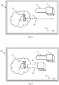
- FIG. 11 shows a schematic representation of a graphic representation 41 which is generated by the data processing device 27 and displayed in a visually perceptible manner by the display device 29.
- the graphic representation 41 can comprise a multiplicity of graphic objects.
- the display device 29 is, for example, "augmented reality" glasses (AR glasses), which simultaneously enable a user to directly view a real-world scene on the one hand and to view virtual objects of the augmented reality on the other.
- the display device 27 in the manner of AR glasses has a display area 55 which can be viewed by a viewer.
- the graphic representation 41 is displayed in a visually perceptible manner on the display area 55.
- the display area 55 is moreover transparent, so that the real-world scene can be viewed directly in the areas of the display area 55 in which the graphic representation 41 does not have any graphic objects.
- the graphic objects contained in the graphic representation 41 can therefore be viewed in the context of the real-world scene.
- the real-world scene is thus expanded by the AR glasses with graphic objects of the graphic representation 41 that are not contained in the real-world scene itself.
- Figure 3 shows a schematic representation of the graphic representation 41 in the environment of a real-world scene by a display device 27 in the manner of AR glasses.
- the real-world scene comprises the irradiation device 1, the applicator 3, the applicator guide 5 with marking 35 and the object 31.
- the graphic representation 41 comprises an introduction assistance graphic object 43.
- the introduction assistance graphic object 43 comprises a guideline 45.
- the guideline 45 is represented by a dashed line with diamonds at the ends.
- the graphical representation of guidelines is not limited to this.
- the display of the graphic representation 41 with the guideline 45 by the display device 29 in the vicinity of the real-world scene makes it easier for a viewer to introduce the applicator 3 into the applicator guide 5.
- the position and orientation of the insertion assistant graphic object 43 or the position and orientation of the guideline 45 in the graphic representation 41 are determined by the data processing section 39, for example, in such a way that the insertion assistant graphic object 43 or the guideline 45 is an extension of the cavity 19 of the applicator guide 5 appears.
- the guideline 45 can be positioned in the graphic representation 41 in such a way that it appears as if the guideline 45 would pass through the opening 21 of the applicator guide 5.
- the data processing section 39 determines the position and orientation of the insertion assistant graphic object 43 or the guideline 45 on the basis of the position and orientation of the applicator guide 5 previously recorded by means of the navigation system 25.
- the graphic display or the position and orientation of the graphic objects of the graphic display depends on the position and direction from which the viewer is viewing the real-world scene.
- the navigation system 25 can furthermore be configured to detect the position and orientation of the display device 29, and the data processing device 27 can be configured to furthermore based the position and orientation of the introductory assistance graphic object 43 in the graphic representation 41 on the detected position and orientation of the display device 29 to be determined.
- the data processing device 27 causes the display device 29 to display the introduction assistance graphic object 43 at the specific position in the specific orientation in the graphic representation 41. Due to its shape and its representation at the specific position in the specific orientation, the insertion assistance graphic object 43 is suitable for making it easier for a viewer to insert the applicator 3 into the applicator guide 5. This takes place in that the viewer looks at the displayed graphic representation 41 in the vicinity of the real-world scene and receives visual aid from the shape and position and orientation of the illustrated introductory assistance graphic object 43, which simplifies the positioning and orientation of the applicator 3.
- Figure 4 shows a schematic representation of a further graphic representation 47 in the vicinity of a real-world scene by a display device 27 in the manner of AR glasses.
- the graphic representation 47 is generated by the data processing device 27 and displayed by the display device 29.
- the introduction assistance graphic object 43 comprises a graphic object 49 which reproduces the shape of the applicator 3 (and of the irradiation device 1).
- the data processing section 39 determines the position and orientation of the graphic object 49 in the graphic representation 47, for example, in such a way that they represent a target position and a target orientation for the applicator 3, which is to be achieved by moving the applicator 3 in order to move the applicator 3 into the applicator guide 5 to be able to introduce.
- the position and orientation of the graphic object 49 in the graphic representation 47 are determined in such a way that the graphic object 49 appears as an extension of the cavity 19 of the applicator guide 5.
- the data processing device 27 comprises a data memory from which shape data can be obtained that represent the shape of the applicator 3.
- Shape data represent the spatial shape of a real world object. These shape data are used to display the graphic object 49 or to display the introduction assistance graphic object 43.
- the navigation system 25 can also be configured to determine the position and / or orientation of the applicator 3.
- the technology for capturing the position and / or orientation of the applicator 3 can be the same as the technology for capturing the position and orientation of the applicator guide 5.
- the position and / or orientation of the applicator 3 can be captured by the navigation system 25 using a different technology .
- the data processing section 39 can also be configured to determine an auxiliary variable based on the detected position and / or orientation of the applicator 3 and on the detected position and / or orientation of the applicator guide 5.
- the auxiliary variable is, for example, a distance between the applicator 3 and the applicator guide 5.
- the data processing section 39 uses, for example, the position of the applicator 3 and the position of the applicator guide 5 as well as shape data, which represent the shape of the applicator 3 and the shape of the applicator guide 5.
- the determination of the auxiliary variable is based on the detected position of the applicator 3 and / or on the detected orientation of the applicator 3 and / or on the detected position of the applicator guide 5 and / or on the detected orientation of the applicator guide 5 and / or Shape data about the applicator 3 and / or shape data about the applicator guide 5.
- the data processing section 39 is further configured to display the auxiliary variable as part of the introduction assistance graphic object 43.
- Figure 5 shows a schematic representation of a graphic representation 51 in the vicinity of a real-world scene by a display device 27 in the manner of AR glasses.
- the graphic representation 51 is generated by the data processing device 27 and displayed by the display device 29.
- the graphic representation 51 comprises an introduction assistance graphic object 43, which comprises an auxiliary variable 53.
- the auxiliary variable 53 is represented by a double arrow and represents the distance between the applicator 3 and the applicator guide 5 determined by the data processing section 39.
- Figure 6 shows a schematic representation of a graphic representation 57 which is generated by the data processing device 27 and displayed by the display device 29.
- the display device 29 is, for example, “virtual reality” glasses or a monitor. These devices display an image 59, which includes the graphic representation 57, to a viewer.
- the image area of the image 59 does not include any real-world objects, but only objects of virtual reality.
- a conventional photography is a Recording of a real-world scene and the visually visible reproduction of the recording, an image that only represents objects of virtual reality.
- the graphic representation 57 comprises a multiplicity of graphic objects which represent real-world objects.
- the graphic representation 57 comprises an image area 1 'which represents the reproduction of the recording of the irradiation device 1, an image area 3' which represents the reproduction of the recording of the applicator 3, an image area 5 'which represents the reproduction of the recording of the applicator guide 5 , and an image area 31 ′, which represents the reproduction of a picture of the object 31.
- the image areas 1 ', 3', 5 'and 31' are graphic objects of the graphic representation 57, which represent real-world objects.
- the graphic representation 57 also includes graphic objects that represent virtual objects.
- the graphic representation 57 includes, for example, the introduction assistance graphic object 43 which was added to the recording of the real-world scene by image processing by the data processing section 39.
- the insertion assistance graphic object 43 is suitable for making it easier for a viewer to insert the applicator 3 into the applicator guide 5. This takes place in that the viewer looks at the displayed graphic representation 57 and, through the shape and position and orientation of the illustrated introductory assistant graphic object 43, receives a visual aid that simplifies the positioning and orientation of the applicator 3.
Landscapes
- Health & Medical Sciences (AREA)
- Engineering & Computer Science (AREA)
- Biomedical Technology (AREA)
- Public Health (AREA)
- Nuclear Medicine, Radiotherapy & Molecular Imaging (AREA)
- General Health & Medical Sciences (AREA)
- Life Sciences & Earth Sciences (AREA)
- Veterinary Medicine (AREA)
- Animal Behavior & Ethology (AREA)
- Radiology & Medical Imaging (AREA)
- Pathology (AREA)
- Surgery (AREA)
- Medical Informatics (AREA)
- Urology & Nephrology (AREA)
- Epidemiology (AREA)
- Primary Health Care (AREA)
- Robotics (AREA)
- Heart & Thoracic Surgery (AREA)
- Molecular Biology (AREA)
- Radiation-Therapy Devices (AREA)
- Processing Or Creating Images (AREA)
Abstract
Description
- Die vorliegende Erfindung betrifft ein Verfahren zur Vorbereitung einer Brachytherapie, ein Brachytherapieverfahren und ein Brachytherapiesystem. Insbesondere betrifft die vorliegende Erfindung ein Hilfsmittel zum Einführen eines Applikators, der auf eine Strahlungsquelle aufgesetzt werden kann, in eine Applikatorführung, welche in einen zu bestrahlenden Gegenstand eingeführt werden kann.
- Im Bereich der Brachytherapie unter Verwendung von Röntgenstrahlung existieren Therapien, bei denen Röntgenstrahlung im Inneren eines Gegenstands, insbesondere eines menschlichen oder tierischen Körpers, in der Nähe eines zu bestrahlenden Bereichs, insbesondere in der Nähe von zu therapierendem Gewebe, erzeugt werden soll. Die Röntgenstrahlung kann hierbei durch ein Bestrahlungsgerät bereitgestellt werden. Ein beispielhaftes Bestrahlungsgerät umfasst ein Teilchenstrahlsystem, welches einen hochenergetischen Teilchenstrahl erzeugen kann. Der Teilchenstrahl wird durch ein einige Zentimeter langes Rohr des Bestrahlungsgeräts auf ein Röntgen-Material gerichtet, welches am Ende des Rohres angeordnet ist. Durch Wechselwirkung des Teilchenstrahls mit dem Röntgen-Material wird von dem Röntgen-Material Röntgenstrahlung emittiert. Diese Röntgenstrahlung tritt durch das Rohr aus und trifft auf den zu bestrahlenden Bereich.
- Damit die von dem Röntgen-Material an der Spitze des Rohres erzeugte Röntgenstrahlung im Inneren eines Gegenstands appliziert werden kann, wird das Rohr in den Gegenstand eingeführt. Hierzu ist das Rohr von einem Applikator umgeben, welcher einerseits eine sterile Barriere darstellt und andererseits das Rohr schützt.
- Vor dem Einführen des Rohres in den Gegenstand wird in den Gegenstand eine Applikatorführung eingeführt. Die Applikatorführung umfasst beispielsweise einen rohrförmigen Abschnitt, der an einem Ende eine Öffnung zum Einführen des Applikators aufweist. Nachdem die Applikatorführung in den Gegenstand eingeführt wurde, kann das mit dem Applikator versehene Bestrahlungsgerät durch die Öffnung des rohrförmigen Abschnitts in die Applikatorführung eingeführt werden. Auf diese Weise wird das Röntgen-Material im Inneren des Gegenstands angeordnet. Daraufhin kann das Röntgen-Material durch Wechselwirkung mit dem Teilchenstrahl die Röntgenstrahlung im Inneren des Gegenstands erzeugen.
- Bei dieser Vorgehensweise besteht jedoch das Problem, dass von der Applikatorführung nur noch ein kurzer Abschnitt zu sehen ist, sobald die Applikatorführung in den Gegenstand eingeführt wurde. Es kann daher schwierig sein, die Orientierung der Applikatorführung mit dem Auge zu erkennen. Beim Einführen des Applikators in die Applikatorführung muss der Applikator jedoch relativ genau zu der Applikatorführung ausgerichtet sein, damit der Applikator und das darin angeordnete Rohr des Bestrahlungsgeräts beim Einführen nicht verbogen werden. Wenn das Rohr verbogen ist, ist die Erzeugung der Röntgenstrahlung gestört.
- Es ist daher eine Aufgabe der vorliegenden Erfindung, ein Hilfsmittel bereitzustellen, welches das Einführen des Applikators in die Applikatorführung erleichtert.
- Ein erster Aspekt der Erfindung betrifft ein Verfahren zur Vorbereitung einer Brachytherapie, wobei das Verfahren umfasst: Bereitstellen eines Applikators und einer Applikatorführung, wobei die Applikatorführung so ausgebildet ist, dass der Applikator in die Applikatorführung eingeführt werden kann und die Applikatorführung die Bewegung des Applikators beim Einführen des Applikators in die Applikatorführung führt; Erfassen einer Position und Orientierung der Applikatorführung durch ein Navigationssystem; Bestimmen einer Position und Orientierung eines Einführungsassistenz-Grafikobjekts in einer grafischen Darstellung basierend auf der erfassten Position und Orientierung der Applikatorführung durch eine Datenverarbeitungsvorrichtung; Anzeigen des Einführungsassistenz-Grafikobjekts in der grafischen Darstellung an der bestimmten Position in der bestimmten Orientierung durch eine Anzeigevorrichtung, wobei das Einführungsassistenz-Grafikobjekt durch seine Gestalt dazu geeignet ist, das Einführen des Applikators in die Applikatorführung durch einen Betrachter zu erleichtern.
- Die Position und Orientierung des Einführungsassistenz-Grafikobjekts können beispielsweise durch Berechnung durch die Datenverarbeitungsvorrichtung bestimmt werden, wobei die Berechnung die erfasste Position und Orientierung der Applikatorführung verwendet. Da die Position und die Orientierung des Einführungsassistenz-Grafikobjekts in Abhängigkeit der erfassten Position der (realweltlichen) Applikatorführung bestimmt werden, ändern sich die Position und Orientierung des Einführungsassistenz-Grafikobjekts, wenn sich die Position und Orientierung der (realweltlichen) Applikatorführung ändert.
- Hierin bezeichnet ein Grafikobjekt ein virtuelles Objekt, das nur durch seine visuelle Darstellung einem menschlichen Beobachter sichtbar wird. Ein Grafikobjekt hat keinen massebehafteten Körper. Ein Grafikobjekt hat eine Gestalt, die eine Gestalt eines realweltlichen Objekts nachbilden kann. Beispielsweise kann das Einführungsassistenz-Grafikobjekt eine Gestalt haben, die die Gestalt des Applikators nachbildet. Die Gestalt eines realweltlichen Objekts ist durch seine körperliche Form gegeben.
- Einzelne oder alle Schritte des Verfahrens können wiederholt werden. Beispielsweise können das Erfassen der Position und Orientierung der Applikatorführung, das Bestimmen der Position und Orientierung des Einführungsassistenz-Grafikobjekt in der grafischen Darstellung und das Anzeigen des Einführungsassistenz-Grafikobjekts wiederholt durchgeführt werden. Hierdurch wirkt sich eine Änderung der Position und Orientierung der Applikatorführung auf die Darstellung des Einführungsassistenz-Grafikobjekts dahingehend aus, dass das Einführungsassistenz-Grafikobjekt an der neu bestimmten Position in der neu bestimmten Orientierung dargestellt wird.
- Das obige Verfahren bewirkt, dass das Einführungsassistenz-Grafikobjekt an einer bestimmten Position in einer bestimmen Orientierung dargestellt wird und somit durch einen Betrachter, der den Applikator in die Applikatorführung einführen möchte, visuell betrachtet werden kann. Das Einführungsassistenz-Grafikobjekt ist dem Betrachter durch seine Gestalt und seine bestimmte Position und Orientierung eine Hilfe beim Einführen des Applikators in die Applikatorführung, da es dem Betrachter eine Anleitung oder Anweisung zum Bewegen des Applikators bereitstellt.
- Ein zweiter Aspekt der Erfindung betrifft ein Brachytherapieverfahren. Das Brachytherapieverfahren umfasst die Schritte des Verfahrens zur Vorbereitung einer Brachytherapie gemäß dem ersten Aspekt, wobei vor dem Erfassen der Position und Orientierung der Applikatorführung die Applikatorführung in einen Gegenstand, insbesondere einen menschlichen oder tierischen Körper, eingeführt wird und wobei bei dem Erfassen der Position und Orientierung der Applikatorführung die Position und die Orientierung der in den Gegenstand eingeführten Applikatorführung erfasst werden. Das Brachytherapieverfahren kann insbesondere weiter umfassen: Einführen des Applikators in die Applikatorführung unter Verwendung des dargestellten Einführungsassistenz-Grafikobjekts; und/oder Erzeugen von Röntgenstrahlung im Inneren des in die Applikatorführung eingeführten Applikators.
- Ein dritter Aspekt der Erfindung betrifft ein System, insbesondere ein Brachytherapiesystem, welches so konfiguriert ist, dass damit die hierin beschriebenen Verfahren durchgeführt werden können. Das System umfasst insbesondere einen Applikator, eine Applikatorführung, ein Navigationssystem, eine Datenverarbeitungsvorrichtung und eine Anzeigevorrichtung.
- Ausführungsformen der Erfindung werden nachfolgend anhand von Figuren näher erläutert. Hierbei zeigt:
- Figur 1
- eine schematische Darstellung eines Bestrahlungsgeräts, eines Applikators und einer Applikatorführung;
- Figur 2
- eine schematische Darstellung eines Brachytherapiesystems;
- Figur 3
- eine schematische Darstellung einer grafischen Darstellung mit Objekten der erweiterten Realität zur Anzeige durch eine Anzeigevorrichtung;
- Figur 4
- eine schematische Darstellung einer weiteren grafischen Darstellung mit Objekten der erweiterten Realität zur Anzeige durch eine Anzeigevorrichtung;
- Figur 5
- eine schematische Darstellung einer weiteren grafischen Darstellung mit Objekten der erweiterten Realität zur Anzeige durch eine Anzeigevorrichtung; und
- Figur 6
- eine schematische Darstellung einer grafischen Darstellung mit Objekten der virtuellen Realität zur Anzeige durch eine Anzeigevorrichtung.
-
Figur 1 zeigt in schematischer Darstellung ein Bestrahlungsgerät 1, einen Applikator 3 und eine Applikatorführung 5. - Das Bestrahlungsgerät 1 umfasst ein einige Zentimeter langes Rohr 7, an dessen einem Ende ein Röntgen-Material 9 angeordnet ist. Das Bestrahlungsgerät 1 umfasst ferner ein Teilchenstrahlsystem 11, welches dazu konfiguriert ist, einen Teilchenstrahl zu erzeugen und durch das Rohr 7 auf das Röntgen-Material 9 zu richten. Hierdurch wird Röntgenstrahlung durch Wechselwirkung des Teilchenstrahls mit dem Röntgen-Material 9 erzeugt. Das Bestrahlungsgerät 1 kann von einem Stativ getragen werden, was die Handhabung (Bewegung und Orientierung) des Bestrahlungsgeräts 1 für einen Nutzer erleichtert. Das Bestrahlungsgerät 1 kann anders konfiguriert sein. Die Erfindung ist auf alle Bestrahlungsgeräte anwendbar, die das Rohr 7 oder einen funktionell ähnlichen länglichen Abschnitt aufweisen.
- Der Applikator 3 hat in dem in
Figur 1 gezeigten Beispiel eine zylinderförmige Gestalt. Der Applikator 3 kann jedoch auch andere Gestalten aufweisen. Der Applikator 3 weist einen auf die Gestalt des Rohres 7 des Bestrahlungsgeräts 1 angepassten Hohlraum 13 im Inneren des Applikators 3 auf. Der Hohlraum 13 ist durch gestrichelte Linien schematisch dargestellt. Der Hohlraum 13 erstreckt sich bis zu einer Öffnung 15 des Applikators 3. Die Öffnung 15 und der daran anschließende Hohlraum 13 sind so gestaltet, dass das Rohr 7 des Bestrahlungsgeräts 1 wenigstens teilweise durch die Öffnung 15 in den Hohlraum 13 des Applikators 3 eingeführt werden kann. Das Rohr 7 kann in der Praxis einige Zentimeter in den Hohlraum 13 eingeführt werden. Die Gestalt des Hohlraumes 13 des Applikators 3 bewirkt eine Führung des Rohres 7 beim Einführen des Rohres 7 in den Hohlraum 13 des Applikators 3. Wenn der Applikator 3 auf diese Weise auf das Bestrahlungsgerät 1 aufgesetzt ist, schützt der Applikator 3 das Rohr 7 des Bestrahlungsgeräts 1 vor äußeren Einflüssen. - Die Applikatorführung 5 weist in dem in
Figur 1 gezeigten Beispiel eine im Wesentlichen zylinderförmige Gestalt mit einem abgerundeten Ende 17 auf. Das abgerundete Ende 17 dient der einfachen Einführung der Applikatorführung 5 in einen Gegenstand. Die Applikatorführung 5 weist im Inneren einen Hohlraum 19 auf, der sich bis zu einer Öffnung 21 erstreckt. Die Öffnung 21 und der Hohlraum 19 der Applikatorführung 5 sind so gestaltet, dass der Applikator 3 wenigstens teilweise durch die Öffnung 21 in den Hohlraum 19 der Applikatorführung 5 eingeführt werden kann. Die Applikatorführung 5 kann in der Praxis einige Zentimeter in den Gegenstand 31 eingeführt werden. Die Gestalt des Hohlraumes 19 der Applikatorführung 5 bewirkt eine Führung des Applikators 3 beim Einführen des Applikators 3 in den Hohlraum 19 der Applikatorführung 5. -
Figur 2 zeigt in schematischer Darstellung ein Brachytherapiesystem 23, mit welchem die hierin beschriebenen Verfahren durchgeführt werden können. Das Brachytherapiesystem 23 umfasst den Applikator 3, die Applikatorführung 5, ein Navigationssystem 25, eine Datenverarbeitungsvorrichtung 27 und eine Anzeigevorrichtung 29. - In der in
Figur 2 dargestellten Situation ist das Bestrahlungsgerät 1 in den Applikator 3 eingeführt. Ferner ist die Applikatorführung 5 in einen Gegenstand 31 eingeführt. Lediglich ein kurzer Abschnitt der Applikatorführung 5, welcher die Öffnung 21 aufweist, ragt noch aus dem Gegenstand 31 heraus. Dies ist eine typische Situation während einem Brachytherapieverfahren. Hierbei wird das Problem deutlich, dass die Orientierung der Applikatorführung 5 schwer zu erkennen ist, da ein Großteil der Applikatorführung 5 in dem Gegenstand 31 angeordnet ist und daher nicht sichtbar ist. Es ist daher schwierig, den Applikator 3 in die Applikatorführung 5 einzuführen, da die Orientierung des Applikators 3 auf die Orientierung der Applikatorführung 5 auszurichten ist, was jedoch schwierig ist, wenn die Orientierung der Applikatorführung 5 selbst schwer zu erkennen ist. - Dieses Problem wird durch das Brachytherapiesystem 23 wie nachfolgend erläutert gelöst.
- Das Navigationssystem 25 ist dazu konfiguriert, die Position und die Orientierung der Applikatorführung 5 zu erfassen. Das Navigationssystem 25 kann auf diverse Weisen konfiguriert sein. Das in den Figuren dargestellte und hierin beschriebene Navigationssystem 25 zeigt lediglich eine mögliche Konfiguration.
- Das Navigationssystem 25 umfasst mehrere Kameras 33, welche dazu konfiguriert sind ein Bild bzw. ein Video der (in den Gegenstand 31 eingeführten) Applikatorführung 5 aufzunehmen. Die Kameras 33 können beispielsweise herkömmliche Farbbildkameras sein.
- Das Navigationssystem 25 umfasst ferner eine Markierung 35. Die Markierung 35 ist in einer bekannten Position und Orientierung bezüglich der Applikatorführung 5 mit der Applikatorführung 5 verbindbar. Wenn die Markierung 35 in der bekannten Position und Orientierung bezüglich der Applikatorführung 5 mit der Applikatorführung 5 verbunden ist, so wie dies in
Figur 2 gezeigt ist, ändert sich die Orientierung der Markierung 35 gemäß der Änderung der Orientierung der Applikatorführung 5. Wenn die Markierung 35 in der bekannten Position und Orientierung bezüglich der Applikatorführung 5 mit der Applikatorführung 5 verbunden ist, können die Position und Orientierung der Applikatorführung 5 basierend auf der Position und Orientierung der Markierung 35 bestimmt werden, da der räumliche Zusammenhang bekannt ist. - In dem in
Figur 2 gezeigten Beispiel besteht die Markierung 35 aus drei Stäben, die zueinander jeweils orthogonal orientiert sind. An den Enden der Stäbe befinden sich eine Kugel, ein Würfel und eine Pyramide. Diese Konfiguration der Markierung 35 erlaubt es, die Position und Orientierung der Markierung 35 auf Grundlage der Bilder zu bestimmen, die von den Kameras 33 aufgenommen werden. Die in Zusammenhang mitFigur 2 erläuterte Konfiguration der Markierung 35 ist lediglich beispielhaft. Beispielsweise können statt der Kugel, dem Würfel und der Pyramide andere unterscheidbare Markierungselemente, beispielsweise drei gleiche Symbole mit unterschiedlichen Farben oder dergleichen, verwendet werden. - Das Navigationssystem 25 umfasst ferner einen Datenverarbeitungsabschnitt 37, welcher beispielsweise in der Datenverarbeitungsvorrichtung 27 bereitgestellt ist. Der Datenverarbeitungsabschnitt 37 für das Navigationssystem 25 empfängt die von den Kameras 33 aufgenommenen Bilder und bestimmt daraus die Position und Orientierung der Markierung 35 und daraus die Position und Orientierung der Applikatorführung 5. Die Bestimmung der Position und Orientierung der Applikatorführung 5 ist nicht auf das hierin beschrieben Beispiel beschränkt. Andere Techniken können hierzu verwendet werden.
- Basierend auf der erfassten Position und Orientierung der Applikatorführung 5 bestimmt ein Datenverarbeitungsabschnitt 39 der Datenverarbeitungsvorrichtung 27 eine Position und Orientierung eines Einführungsassistenz-Grafikobjekts in einer grafischen Darstellung, welche mittels der Anzeigevorrichtung 29 angezeigt wird. Dies wird nachfolgend mit Bezug zu den
Figuren 3 und 4 näher erläutert. -
Figur 3 zeigt eine schematische Darstellung einer grafischen Darstellung 41, die durch die Datenverarbeitungsvorrichtung 27 erzeugt und durch die Anzeigevorrichtung 29 visuell wahrnehmbar angezeigt wird. Die grafische Darstellung 41 kann eine Vielzahl von Grafikobjekten umfassen. - Die Anzeigevorrichtung 29 ist beispielsweise eine "augmented reality"-Brille (AR-Brille), welche einem Nutzer gleichzeitig die direkte unmittelbare Betrachtung einer realweltlichen Szene einerseits und die Betrachtung von virtuellen Objekten der erweiterten Realität andererseits ermöglicht. Die Anzeigevorrichtung 27 nach Art der AR-Brille weist einen Anzeigebereich 55 auf, der von einem Betrachter betrachtet werden kann. Auf dem Anzeigebereich 55 wird die grafische Darstellung 41 visuell wahrnehmbar angezeigt. Der Anzeigebereich 55 ist im Übrigen transparent, sodass in den Bereichen des Anzeigebereichs 55, an denen die grafische Darstellung 41 keine Grafikobjekte aufweist, die realweltliche Szene unmittelbar betrachtet werden kann. Die in der grafischen Darstellung 41 enthaltenen Grafikobjekte können daher im Umfeld der realweltlichen Szene betrachtet werden. Somit wird durch die AR-Brille die realweltliche Szene mit Grafikobjekten der grafischen Darstellung 41 erweitert, die in der realweltlichen Szene selbst nicht enthalten sind.
-
Figur 3 zeigt in schematischer Darstellung die grafische Darstellung 41 im Umfeld einer realweltlichen Szene durch eine Anzeigevorrichtung 27 nach Art der AR-Brille. - Die realweltliche Szene umfasst das Bestrahlungsgerät 1, den Applikator 3, die Applikatorführung 5 mit Markierung 35 und den Gegenstand 31.
- Die grafische Darstellung 41 umfasst ein Einführungsassistenz-Grafikobjekt 43. In dem in
Figur 3 gezeigten Beispiel umfasst das Einführungsassistenz-Grafikobjekt 43 eine Leitlinie 45. Die Leitlinie 45 wird durch eine gestrichelte Linie mit Rauten an den Enden dargestellt. Die grafische Darstellung von Leitlinien ist darauf nicht beschränkt. Die Anzeige der grafischen Darstellung 41 mit der Leitlinie 45 durch die Anzeigevorrichtung 29 im Umfeld der realweltlichen Szene erleichtert einem Betrachter die Einführung des Applikators 3 in die Applikatorführung 5. - Durch den Datenverarbeitungsabschnitt 39 werden die Position und Orientierung des Einführungsassistenz-Grafikobjekts 43 bzw. die Position und Orientierung der Leitlinie 45 in der grafischen Darstellung 41 beispielsweise so bestimmt, dass das Einführungsassistenz-Grafikobjekt 43 bzw. die Leitlinie 45 in Verlängerung des Hohlraums 19 der Applikatorführung 5 erscheint. Das bedeutet beispielsweise, dass die Leitlinie 45 so angezeigt wird, als wäre sie im realweltlichen Raum parallel zu dem zylinderförmigen Hohlraum 19 der Applikatorführung 5 orientiert. Die Leitlinie 45 kann dabei in der grafischen Darstellung 41 so positioniert sein, dass sie so erscheint, als würde die Leitlinie 45 die Öffnung 21 der Applikatorführung 5 durchsetzen.
- Um die Position und Orientierung des Einführungsassistenz-Grafikobjekts 43 bzw. der Leitlinie 45 in der grafischen Darstellung 41 an der realweltlichen Position und Orientierung der Applikatorführung 5 ausrichten zu können, bestimmt der Datenverarbeitungsabschnitt 39 die Position und Orientierung des Einführungsassistenz-Grafikobjekts 43 bzw. der Leitlinie 45 auf Basis der zuvor mittels des Navigationssystems 25 erfassten Position und Orientierung der Applikatorführung 5.
- Bei der Anzeige durch eine AR-Brille hängt die grafische Darstellung bzw. die Position und Orientierung der Grafikobjekte der grafischen Darstellung von der Position und Richtung ab, aus welcher der Betrachter die realweltliche Szene betrachtet. Um dies berücksichtigen zu können, kann das Navigationssystem 25 ferner dazu konfiguriert sein, die Position und Orientierung der Anzeigevorrichtung 29 zu erfassen, und die Datenverarbeitungsvorrichtung 27 kann dazu konfiguriert sein, die Position und Orientierung des Einführungsassistenz-Grafikobjekts 43 in der grafischen Darstellung 41 ferner basierend auf der erfassten Position und Orientierung der Anzeigevorrichtung 29 zu bestimmen.
- Die Datenverarbeitungsvorrichtung 27 veranlasst die Anzeigevorrichtung 29, das Einführungsassistenz-Grafikobjekt 43 an der bestimmten Position in der bestimmten Orientierung in der grafischen Darstellung 41 anzuzeigen. Durch seine Gestalt und seine Darstellung an der bestimmten Position in der bestimmten Orientierung ist das Einführungsassistenz-Grafikobjekt 43 dazu geeignet, das Einführen des Applikators 3 in die Applikatorführung 5 durch einen Betrachter zu erleichtern. Dies geschieht, indem der Betrachter die angezeigte grafische Darstellung 41 im Umfeld der realweltlichen Szene betrachtet und durch die Gestalt und die Position und Orientierung des dargestellten Einführungsassistenz-Grafikobjekts 43 eine visuelle Hilfe erhält, die die Positionierung und Orientierung des Applikators 3 vereinfacht.
-
Figur 4 zeigt in schematischer Darstellung eine weitere grafische Darstellung 47 im Umfeld einer realweltlichen Szene durch eine Anzeigevorrichtung 27 nach Art der AR-Brille. Die grafische Darstellung 47 wird von der Datenverarbeitungsvorrichtung 27 erzeugt und durch die Anzeigevorrichtung 29 angezeigt. - In der in
Figur 4 gezeigten grafischen Darstellung 47 umfasst das Einführungsassistenz-Grafikobjekt 43 ein Grafikobjekt 49, welches die Gestalt des Applikators 3 (und des Bestrahlungsgeräts 1) wiedergibt. Der Datenverarbeitungsabschnitt 39 bestimmt die Position und Orientierung des Grafikobjekts 49 in der grafischen Darstellung 47 beispielsweise so, dass sie eine Zielposition und eine Zielorientierung für den Applikator 3 repräsentieren, die durch Bewegen des Applikators 3 erreicht werden soll, um den Applikator 3 in die Applikatorführung 5 einführen zu können. Beispielsweise werden die Position und Orientierung des Grafikobjekts 49 in der grafischen Darstellung 47 so bestimmt, dass das Grafikobjekt 49 in Verlängerung des Hohlraums 19 der Applikatorführung 5 erscheint. Zur Darstellung des Grafikobjekts 49 in Gestalt des Applikators 3 umfasst die Datenverarbeitungsvorrichtung 27 einen Datenspeicher, aus welchem Formdaten erhalten werden können, die die Gestalt des Applikators 3 repräsentieren. Formdaten repräsentieren die räumliche Gestalt eines realweltlichen Gegenstands. Diese Formdaten werden zur Darstellung des Grafikobjekts 49 bzw. zur Darstellung des Einführungsassistenz-Grafikobjekts 43 verwendet. - Eine weitere Ausführungsform wird mit Bezug zu
Figur 5 beschrieben. Das Navigationssystem 25 kann ferner dazu konfiguriert sein, die Position und/oder Orientierung des Applikators 3 zu bestimmen. Die Technik zum Erfassen der Position und/oder Orientierung des Applikators 3 kann gleich sein wie die Technik zum Erfassen der Position und Orientierung der Applikatorführung 5. Alternativ kann die Position und/oder Orientierung des Applikators 3 mit einer anderen Technik durch das Navigationssystem 25 erfasst werden. - Der Datenverarbeitungsabschnitt 39 kann ferner dazu konfiguriert sein, basierend auf der erfassten Position und/oder Orientierung des Applikators 3 und auf der erfassten Position und/oder Orientierung der Applikatorführung 5 eine Hilfsgröße zu bestimmen. Die Hilfsgröße ist beispielsweise ein Abstand zwischen dem Applikator 3 und der Applikatorführung 5. Zum Bestimmen des Abstands zwischen dem Applikator 3 und der Applikatorführung 5 verwendet der Datenverarbeitungsabschnitt 39 beispielsweise die mittels des Navigationssystems 25 erfasste Position des Applikators 3 und Position der Applikatorführung 5 sowie Formdaten, die die Gestalt des Applikators 3 und die Gestalt der Applikatorführung 5 repräsentieren. Je nach Art der Hilfsgröße basiert das Bestimmen der Hilfsgröße auf der erfassten Position des Applikators 3 und/oder auf der erfassten Orientierung des Applikators 3 und/oder auf der erfassten Position der Applikatorführung 5 und/oder auf der erfassten Orientierung der Applikatorführung 5 und/oder Formdaten über den Applikator 3 und/oder Formdaten über die Applikatorführung 5.
- Der Datenverarbeitungsabschnitt 39 ist ferner dazu konfiguriert, die Hilfsgröße als Teil des Einführungsassistenz-Grafikobjekts 43 darzustellen.
-
Figur 5 zeigt eine schematische Darstellung einer grafischen Darstellung 51 im Umfeld einer realweltlichen Szene durch eine Anzeigevorrichtung 27 nach Art der AR-Brille. - Die grafische Darstellung 51 wird durch die Datenverarbeitungsvorrichtung 27 erzeugt und durch die Anzeigevorrichtung 29 angezeigt. Die grafische Darstellung 51 umfasst ein Einführungsassistenz-Grafikobjekt 43, welches eine Hilfsgröße 53 umfasst. Die Hilfsgröße 53 ist durch einen Doppelpfeil dargestellt und repräsentiert den von dem Datenverarbeitungsabschnitt 39 bestimmten Abstand zwischen dem Applikator 3 und der Applikatorführung 5.
- Mit Bezug zu den
Figuren 3 bis 5 wurden Beispiele für grafische Darstellungen erläutert, die im Umfeld einer realweltlichen Szene durch eine Anzeigevorrichtung 27 nach Art der AR-Brille angezeigt werden. Die Art der Anzeige ist darauf nicht beschränkt. Nachfolgend wird mit Bezug zuFigur 6 ein Beispiel erläutert, bei welchem das Einführungsassistenz-Grafikobjekt 43 als Objekt der virtuellen Realität bzw. in einem Bild dargestellt wird. -
Figur 6 zeigt eine schematische Darstellung einer grafischen Darstellung 57, welche von der Datenverarbeitungsvorrichtung 27 erzeugt und durch die Anzeigevorrichtung 29 angezeigt wird. Die Anzeigevorrichtung 29 ist beispielsweise eine "virtual reality"-Brille oder ein Monitor. Diese Geräte zeigen einem Betrachter ein Bild 59 an, welches die grafische Darstellung 57 umfasst. Der Bildbereich des Bildes 59 umfasst keine realweltlichen Objekte, sondern ausschließlich Objekte der virtuellen Realität. In diesem Sinne ist eine konventionelle Fotografie, also eine Aufnahme einer realweltlichen Szene und die visuell sichtbare Wiedergabe der Aufnahme, ein Bild, welches ausschließlich Objekte der virtuellen Realität darstellt. - Die grafische Darstellung 57 umfasst eine Vielzahl von Grafikobjekten, die realweltliche Objekte repräsentieren. Beispielsweise umfasst die grafische Darstellung 57 einen Bildbereich 1', welcher die Wiedergabe der Aufnahme des Bestrahlungsgeräts 1 repräsentiert, einen Bildbereich 3', welcher die Wiedergabe der Aufnahme des Applikators 3 repräsentiert, einen Bildbereich 5', welcher die Wiedergabe der Aufnahme der Applikatorführung 5 repräsentiert, und einen Bildbereich 31', welcher die Wiedergabe einer Aufnahme des Gegenstands 31 repräsentiert. Die Bildbereiche 1', 3', 5' und 31' sind Grafikobjekte der grafischen Darstellung 57, die realweltliche Objekte repräsentieren.
- Die grafische Darstellung 57 umfasst ferner Grafikobjekte, die virtuelle Objekte repräsentieren. Die grafische Darstellung 57 umfasst beispielsweise das Einführungsassistenz-Grafikobjekt 43, welches der Aufnahme der realweltlichen Szene durch Bildbearbeitung durch den Datenverarbeitungsabschnitt 39 hinzugefügt wurde.
- Durch seine Gestalt und seine Darstellung an der bestimmten Position in der bestimmten Orientierung ist das Einführungsassistenz-Grafikobjekt 43 dazu geeignet, das Einführen des Applikators 3 in die Applikatorführung 5 durch einen Betrachter zu erleichtern. Dies geschieht, indem der Betrachter die angezeigte grafische Darstellung 57 betrachtet und durch die Gestalt und die Position und Orientierung des dargestellten Einführungsassistenz-Grafikobjekts 43 eine visuelle Hilfe erhält, die die Positionierung und Orientierung des Applikators 3 vereinfacht.
Claims (13)
- Verfahren zur Vorbereitung einer Brachytherapie, umfassend:Bereitstellen eines Applikators (3) und einer Applikatorführung (5), wobei die Applikatorführung (5) so ausgebildet ist, dass der Applikator (3) in die Applikatorführung (5) eingeführt werden kann und die Applikatorführung (5) die Bewegung des Applikators (3) beim Einführen des Applikators (3) in die Applikatorführung (5) führt;Erfassen einer Position und Orientierung der Applikatorführung (5) durch ein Navigationssystem (25);Bestimmen einer Position und Orientierung eines Einführungsassistenz-Grafikobjekts (43) in einer grafischen Darstellung (41, 47, 51, 57) basierend auf der erfassten Position und Orientierung der Applikatorführung (5) durch eine Datenverarbeitungsvorrichtung (27);Anzeigen des Einführungsassistenz-Grafikobjekts (43) an der bestimmten Position in der bestimmten Orientierung in der grafischen Darstellung (41, 47, 51, 57) durch eine Anzeigevorrichtung (29),wobei das Einführungsassistenz-Grafikobjekt (43) durch seine Gestalt dazu geeignet ist, das Einführen des Applikators (3) in die Applikatorführung (5) durch einen Betrachter zu erleichtern.
- Verfahren nach Anspruch 1, wobei das Einführungsassistenz-Grafikobjekt (43) ein Grafikobjekt (49) umfasst, welches die Gestalt des Applikators (3) wiedergibt.
- Verfahren nach Anspruch 2, ferner umfassend:Erhalten von Formdaten, die die Gestalt des Applikators (3) repräsentieren, aus einem Datenspeicher; undVerwenden der Formdaten bei dem Darstellen des Einführungsassistenz-Grafikobjekts (43).
- Verfahren einem der Ansprüche 1 bis 3, wobei das Einführungsassistenz-Grafikobjekt (43) mindestens eine Leitlinie (45) umfasst.
- Verfahren einem der Ansprüche 1 bis 4, wobei die Position und die Orientierung des Einführungsassistenz-Grafikobjekts (43) an der erfassten Position und Orientierung der Applikatorführung (5) ausgerichtet sind.
- Verfahren nach einem der Ansprüche 1 bis 5,
wobei die Applikatorführung (5) einen Hohlraum (19) umfasst, in welchen der Applikator (3) einzuführen ist, und
wobei die Position und Orientierung des Einführungsassistenz-Grafikobjekts (43) in der grafischen Darstellung (41, 47, 51, 57) so bestimmt werden, dass das Einführungsassistenz-Grafikobjekt (43) in Verlängerung des Hohlraums (19) erscheint. - Verfahren nach einem der Ansprüche 1 bis 6, wobei die Position und Orientierung des Einführungsassistenz-Grafikobjekts (43) so bestimmt werden, dass sie eine Zielposition und eine Zielorientierung für den Applikator (3) repräsentieren, die durch Bewegen des Applikators (3) erreicht werden soll, um den Applikator (3) in die Applikatorführung (5) einführen zu können.
- Verfahren nach einem der Ansprüche 1 bis 7, ferner umfassend:Erfassen einer Position und Orientierung des Applikators (3) durch das Navigationssystem (25);Bestimmen einer Hilfsgröße (53), insbesondere eines Abstands zwischen dem Applikator (3) und der Applikatorführung (5), basierend auf der erfassten Position und/oder Orientierung des Applikators (3) und auf der erfassten Position und/oder Orientierung der Applikatorführung (5); undDarstellen der Hilfsgröße (53) als Teil des Einführungsassistenz-Grafikobjekts (43).
- Verfahren nach einem der Ansprüche 1 bis 8, ferner umfassend:Erfassen einer Position und Orientierung der Anzeigevorrichtung (29);wobei die Position und die Orientierung des Einführungsassistenz-Grafikobjekts (43) in der grafischen Darstellung (41, 47, 51, 57) ferner basierend auf der erfassten Position und Orientierung der Anzeigevorrichtung (29) bestimmt werden.
- Verfahren nach einem der Ansprüche 1 bis 9,
wobei das Einführungsassistenz-Grafikobjekt (43) als Objekt der erweiterten Realität, als Objekt der virtuellen Realität und/oder in einem Bild (59) dargestellt wird. - Brachytherapieverfahren, umfassend:das Verfahren nach einem Ansprüche 1 bis 10,wobei vor dem Erfassen der Position und Orientierung der Applikatorführung (5) die Applikatorführung (5) in einen Gegenstand (31), insbesondere einen menschlichen oder tierischen Körper, eingeführt wird undwobei bei dem Erfassen der Position und Orientierung der Applikatorführung (5) die Position und die Orientierung der in den Gegenstand (31) eingeführten Applikatorführung (5) erfasst werden.
- Brachytherapieverfahren Anspruch 11, ferner umfassend:Einführen des Applikators (3) in die Applikatorführung (5) unter Verwendung des dargestellten Einführungsassistenz-Grafikobjekts (43); und/oderErzeugen von Röntgenstrahlung im Inneren des in die Applikatorführung (5) eingeführten Applikators (3).
- Brachytherapiesystem (23), umfassend:einen Applikator (3);eine Applikatorführung (5);ein Navigationssystem (25);eine Datenverarbeitungsvorrichtung (27); undeine Anzeigevorrichtung (29),wobei das Brachytherapiesystem (23) so konfiguriert ist, dass ein Verfahren gemäß einem der Ansprüche 1 bis 12 damit durchführbar ist.
Applications Claiming Priority (1)
| Application Number | Priority Date | Filing Date | Title |
|---|---|---|---|
| DE102020102213.1A DE102020102213A1 (de) | 2020-01-30 | 2020-01-30 | Verfahren zur Vorbereitung einer Brachytherapie, Brachytherapieverfahren und Brachytherapiesystem |
Publications (1)
| Publication Number | Publication Date |
|---|---|
| EP3858282A1 true EP3858282A1 (de) | 2021-08-04 |
Family
ID=74418225
Family Applications (1)
| Application Number | Title | Priority Date | Filing Date |
|---|---|---|---|
| EP21154232.9A Withdrawn EP3858282A1 (de) | 2020-01-30 | 2021-01-29 | Verfahren zur vorbereitung einer brachytherapie und brachytherapiesystem |
Country Status (4)
| Country | Link |
|---|---|
| US (1) | US20210236849A1 (de) |
| EP (1) | EP3858282A1 (de) |
| CN (1) | CN113198112A (de) |
| DE (1) | DE102020102213A1 (de) |
Citations (3)
| Publication number | Priority date | Publication date | Assignee | Title |
|---|---|---|---|---|
| US6311084B1 (en) * | 1998-05-04 | 2001-10-30 | Robert A. Cormack | Radiation seed implant method and apparatus |
| US20100016710A1 (en) * | 2008-07-11 | 2010-01-21 | Dinesh Kumar | Prostate treatment apparatus |
| US20170203128A1 (en) * | 2014-07-14 | 2017-07-20 | Koninklijke Philips N.V. | Grid calibration system for interventional procedures |
Family Cites Families (6)
| Publication number | Priority date | Publication date | Assignee | Title |
|---|---|---|---|---|
| CA2333583C (en) * | 1997-11-24 | 2005-11-08 | Everette C. Burdette | Real time brachytherapy spatial registration and visualization system |
| US9895135B2 (en) | 2009-05-20 | 2018-02-20 | Analogic Canada Corporation | Freehand ultrasound imaging systems and methods providing position quality feedback |
| US10245447B2 (en) | 2011-10-18 | 2019-04-02 | Koninklijke Philips N.V. | Magnetic resonance imaging guided brachytherapy with displaying the catheter placement position |
| US10549123B2 (en) * | 2012-12-11 | 2020-02-04 | Koninklijke Philips N.V. | Assisting apparatus for assisting in performing a brachytherapy |
| WO2015039995A1 (en) * | 2013-09-19 | 2015-03-26 | Koninklijke Philips N.V. | High-dose rate brachytherapy system |
| JP6526346B2 (ja) * | 2016-03-16 | 2019-06-05 | コーニンクレッカ フィリップス エヌ ヴェKoninklijke Philips N.V. | 近接照射療法システム及び方法 |
-
2020
- 2020-01-30 DE DE102020102213.1A patent/DE102020102213A1/de not_active Ceased
-
2021
- 2021-01-29 CN CN202110132811.7A patent/CN113198112A/zh active Pending
- 2021-01-29 EP EP21154232.9A patent/EP3858282A1/de not_active Withdrawn
- 2021-01-29 US US17/163,280 patent/US20210236849A1/en not_active Abandoned
Patent Citations (3)
| Publication number | Priority date | Publication date | Assignee | Title |
|---|---|---|---|---|
| US6311084B1 (en) * | 1998-05-04 | 2001-10-30 | Robert A. Cormack | Radiation seed implant method and apparatus |
| US20100016710A1 (en) * | 2008-07-11 | 2010-01-21 | Dinesh Kumar | Prostate treatment apparatus |
| US20170203128A1 (en) * | 2014-07-14 | 2017-07-20 | Koninklijke Philips N.V. | Grid calibration system for interventional procedures |
Also Published As
| Publication number | Publication date |
|---|---|
| DE102020102213A1 (de) | 2021-08-05 |
| US20210236849A1 (en) | 2021-08-05 |
| CN113198112A (zh) | 2021-08-03 |
Similar Documents
| Publication | Publication Date | Title |
|---|---|---|
| DE10114099B4 (de) | Verfahren zum Detektieren der dreidimensionalen Position eines in einen Körperbereich eingeführten medizinischen Untersuchungsinstruments, insbesondere eines in ein Gefäß eingeführten Katheters | |
| EP2082686B1 (de) | Orientierte Wiedergabe von Aufnahmen | |
| DE69922980T2 (de) | Verfahren und vorrichtung zur positionierung eines geräts in einem körper | |
| DE19950793B4 (de) | Röntgeneinrichtung und Verfahren zur Bestimmung von Abbildungsparametern | |
| EP1342488B1 (de) | Verfahren und Vorrichtung zur wiederholt gleichen Relativpositionierung eines Patienten | |
| EP1259185B1 (de) | Verfahren zum navigieren im körperinneren anhand dreidimensional visualisierter strukturen | |
| DE3717871C2 (de) | ||
| DE19843408C2 (de) | Verfahren zur Wiedergabe von Röntgenbildern beim Positionieren eines in ein Gefäß eingeführten Katheters und Vorrichtung zur Durchführung des Verfahrens | |
| DE10136160A1 (de) | Verfahren und Vorrichtung zur Registrierung zweier 3D-Bilddatensätze | |
| DE102004004451A1 (de) | Verfahren und Einrichtung zur medizinischen Bildgebung, wobei ein Objekt einer Röntgenaufnahme reorientiert wird | |
| EP2119397A1 (de) | Bestimmung einer Kalibrier-Information für ein Röntgengerät | |
| DE10240727A1 (de) | Bildgebendes System und Verfahren zur Optimierung einer Röntgenabbildung | |
| DE10160530B4 (de) | Verfahren und Anlage zur Magnetresonanz-Bildgebung | |
| DE102012008812A1 (de) | Röntgenquelle mit Modul und Detektor für optische Strahlung | |
| DE102008013615A1 (de) | Verfahren und Markierungsvorrichtung zur Markierung einer Führungslinie eines Eindringungsinstruments, Steuerungseinrichtung und Aufnahmesystem | |
| DE102005045602A1 (de) | Verfahren zum Unterstützen eines interventionellen medizinischen Eingriffs | |
| WO1993018426A1 (de) | Verfahren und vorrichtung zur darstellung eines arbeitsbereiches in einer dreidimensionalen struktur | |
| DE102005041602A1 (de) | Verfahren zur Darstellung eines medizinischen Implantats in einem Bild sowie medizinisches bildgebendes System | |
| DE102011078405A1 (de) | Verfahren zur Endoskopie mit magnetgeführter Endoskopkapsel sowie Einrichtung dazu | |
| DE10206193C1 (de) | Vorrichtung und Verfahren zur Ausrichtung eines Röntgengerätes und eines Therapiegerätes relativ zueinander | |
| DE102006006038B4 (de) | System zur bildlich dargestellten Verfolgung eines in ein Untersuchungsobjekt mindestens teilweise eingeführten, bewegten medizinischen Instruments | |
| DE102015119887B4 (de) | Behandlungsvorrichtung für eine subretinale Injektion und Verfahren zur Unterstützung bei einer subretinalen Injektion | |
| DE102011076929A1 (de) | Verfahren und Vorrichtung zur Darstellung von Volumendaten für eine Untersuchung von Dichteeigenschaften | |
| EP1795230B1 (de) | Medizinische Bestrahlungseinrichtung | |
| DE102012200686A1 (de) | Verfahren und Vorrichtung zur Positionierung einer Röntgenvorrichtung |
Legal Events
| Date | Code | Title | Description |
|---|---|---|---|
| PUAI | Public reference made under article 153(3) epc to a published international application that has entered the european phase |
Free format text: ORIGINAL CODE: 0009012 |
|
| STAA | Information on the status of an ep patent application or granted ep patent |
Free format text: STATUS: THE APPLICATION HAS BEEN PUBLISHED |
|
| AK | Designated contracting states |
Kind code of ref document: A1 Designated state(s): AL AT BE BG CH CY CZ DE DK EE ES FI FR GB GR HR HU IE IS IT LI LT LU LV MC MK MT NL NO PL PT RO RS SE SI SK SM TR |
|
| STAA | Information on the status of an ep patent application or granted ep patent |
Free format text: STATUS: REQUEST FOR EXAMINATION WAS MADE |
|
| 17P | Request for examination filed |
Effective date: 20220126 |
|
| RBV | Designated contracting states (corrected) |
Designated state(s): AL AT BE BG CH CY CZ DE DK EE ES FI FR GB GR HR HU IE IS IT LI LT LU LV MC MK MT NL NO PL PT RO RS SE SI SK SM TR |
|
| STAA | Information on the status of an ep patent application or granted ep patent |
Free format text: STATUS: EXAMINATION IS IN PROGRESS |
|
| 17Q | First examination report despatched |
Effective date: 20230905 |
|
| GRAP | Despatch of communication of intention to grant a patent |
Free format text: ORIGINAL CODE: EPIDOSNIGR1 |
|
| STAA | Information on the status of an ep patent application or granted ep patent |
Free format text: STATUS: GRANT OF PATENT IS INTENDED |
|
| INTG | Intention to grant announced |
Effective date: 20241203 |
|
| STAA | Information on the status of an ep patent application or granted ep patent |
Free format text: STATUS: THE APPLICATION IS DEEMED TO BE WITHDRAWN |
|
| 18D | Application deemed to be withdrawn |
Effective date: 20250404 |