EP3856535B1 - Dekorfolie, verfahren zum dekorieren eines kunststoffformteils sowie kunststoffformteil - Google Patents
Dekorfolie, verfahren zum dekorieren eines kunststoffformteils sowie kunststoffformteil Download PDFInfo
- Publication number
- EP3856535B1 EP3856535B1 EP19773015.3A EP19773015A EP3856535B1 EP 3856535 B1 EP3856535 B1 EP 3856535B1 EP 19773015 A EP19773015 A EP 19773015A EP 3856535 B1 EP3856535 B1 EP 3856535B1
- Authority
- EP
- European Patent Office
- Prior art keywords
- lacquer layer
- layer
- decorative film
- coloured
- transparent laser
- Prior art date
- Legal status (The legal status is an assumption and is not a legal conclusion. Google has not performed a legal analysis and makes no representation as to the accuracy of the status listed.)
- Active
Links
Images


Classifications
-
- B—PERFORMING OPERATIONS; TRANSPORTING
- B44—DECORATIVE ARTS
- B44C—PRODUCING DECORATIVE EFFECTS; MOSAICS; TARSIA WORK; PAPERHANGING
- B44C1/00—Processes, not specifically provided for elsewhere, for producing decorative surface effects
- B44C1/10—Applying flat materials, e.g. leaflets, pieces of fabrics
-
- B—PERFORMING OPERATIONS; TRANSPORTING
- B29—WORKING OF PLASTICS; WORKING OF SUBSTANCES IN A PLASTIC STATE IN GENERAL
- B29C—SHAPING OR JOINING OF PLASTICS; SHAPING OF MATERIAL IN A PLASTIC STATE, NOT OTHERWISE PROVIDED FOR; AFTER-TREATMENT OF THE SHAPED PRODUCTS, e.g. REPAIRING
- B29C37/00—Component parts, details, accessories or auxiliary operations, not covered by group B29C33/00 or B29C35/00
- B29C37/0025—Applying surface layers, e.g. coatings, decorative layers, printed layers, to articles during shaping, e.g. in-mould printing
- B29C37/0028—In-mould coating, e.g. by introducing the coating material into the mould after forming the article
-
- B—PERFORMING OPERATIONS; TRANSPORTING
- B32—LAYERED PRODUCTS
- B32B—LAYERED PRODUCTS, i.e. PRODUCTS BUILT-UP OF STRATA OF FLAT OR NON-FLAT, e.g. CELLULAR OR HONEYCOMB, FORM
- B32B15/00—Layered products comprising a layer of metal
- B32B15/04—Layered products comprising a layer of metal comprising metal as the main or only constituent of a layer, which is next to another layer of the same or of a different material
- B32B15/08—Layered products comprising a layer of metal comprising metal as the main or only constituent of a layer, which is next to another layer of the same or of a different material of synthetic resin
-
- B—PERFORMING OPERATIONS; TRANSPORTING
- B44—DECORATIVE ARTS
- B44C—PRODUCING DECORATIVE EFFECTS; MOSAICS; TARSIA WORK; PAPERHANGING
- B44C1/00—Processes, not specifically provided for elsewhere, for producing decorative surface effects
- B44C1/16—Processes, not specifically provided for elsewhere, for producing decorative surface effects for applying transfer pictures or the like
- B44C1/165—Processes, not specifically provided for elsewhere, for producing decorative surface effects for applying transfer pictures or the like for decalcomanias; sheet material therefor
- B44C1/17—Dry transfer
- B44C1/1704—Decalcomanias provided with a particular decorative layer, e.g. specially adapted to allow the formation of a metallic or dyestuff layer on a substrate unsuitable for direct deposition
-
- B—PERFORMING OPERATIONS; TRANSPORTING
- B44—DECORATIVE ARTS
- B44C—PRODUCING DECORATIVE EFFECTS; MOSAICS; TARSIA WORK; PAPERHANGING
- B44C3/00—Processes, not specifically provided for elsewhere, for producing ornamental structures
- B44C3/005—Removing selectively parts of at least the upper layer of a multi-layer article
-
- B—PERFORMING OPERATIONS; TRANSPORTING
- B44—DECORATIVE ARTS
- B44C—PRODUCING DECORATIVE EFFECTS; MOSAICS; TARSIA WORK; PAPERHANGING
- B44C3/00—Processes, not specifically provided for elsewhere, for producing ornamental structures
- B44C3/02—Superimposing layers
-
- B—PERFORMING OPERATIONS; TRANSPORTING
- B29—WORKING OF PLASTICS; WORKING OF SUBSTANCES IN A PLASTIC STATE IN GENERAL
- B29C—SHAPING OR JOINING OF PLASTICS; SHAPING OF MATERIAL IN A PLASTIC STATE, NOT OTHERWISE PROVIDED FOR; AFTER-TREATMENT OF THE SHAPED PRODUCTS, e.g. REPAIRING
- B29C37/00—Component parts, details, accessories or auxiliary operations, not covered by group B29C33/00 or B29C35/00
- B29C37/0025—Applying surface layers, e.g. coatings, decorative layers, printed layers, to articles during shaping, e.g. in-mould printing
- B29C37/0028—In-mould coating, e.g. by introducing the coating material into the mould after forming the article
- B29C2037/0046—In-mould printing, in-mould transfer printing
-
- B—PERFORMING OPERATIONS; TRANSPORTING
- B29—WORKING OF PLASTICS; WORKING OF SUBSTANCES IN A PLASTIC STATE IN GENERAL
- B29C—SHAPING OR JOINING OF PLASTICS; SHAPING OF MATERIAL IN A PLASTIC STATE, NOT OTHERWISE PROVIDED FOR; AFTER-TREATMENT OF THE SHAPED PRODUCTS, e.g. REPAIRING
- B29C45/00—Injection moulding, i.e. forcing the required volume of moulding material through a nozzle into a closed mould; Apparatus therefor
- B29C45/16—Making multilayered or multicoloured articles
- B29C45/1679—Making multilayered or multicoloured articles applying surface layers onto injection-moulded substrates inside the mould cavity, e.g. in-mould coating [IMC]
-
- B—PERFORMING OPERATIONS; TRANSPORTING
- B32—LAYERED PRODUCTS
- B32B—LAYERED PRODUCTS, i.e. PRODUCTS BUILT-UP OF STRATA OF FLAT OR NON-FLAT, e.g. CELLULAR OR HONEYCOMB, FORM
- B32B2457/00—Electrical equipment
- B32B2457/20—Displays, e.g. liquid crystal displays, plasma displays
- B32B2457/208—Touch screens
-
- B—PERFORMING OPERATIONS; TRANSPORTING
- B32—LAYERED PRODUCTS
- B32B—LAYERED PRODUCTS, i.e. PRODUCTS BUILT-UP OF STRATA OF FLAT OR NON-FLAT, e.g. CELLULAR OR HONEYCOMB, FORM
- B32B7/00—Layered products characterised by the relation between layers; Layered products characterised by the relative orientation of features between layers, or by the relative values of a measurable parameter between layers, i.e. products comprising layers having different physical, chemical or physicochemical properties; Layered products characterised by the interconnection of layers
- B32B7/04—Interconnection of layers
- B32B7/12—Interconnection of layers using interposed adhesives or interposed materials with bonding properties
-
- B—PERFORMING OPERATIONS; TRANSPORTING
- B44—DECORATIVE ARTS
- B44C—PRODUCING DECORATIVE EFFECTS; MOSAICS; TARSIA WORK; PAPERHANGING
- B44C1/00—Processes, not specifically provided for elsewhere, for producing decorative surface effects
- B44C1/16—Processes, not specifically provided for elsewhere, for producing decorative surface effects for applying transfer pictures or the like
- B44C1/165—Processes, not specifically provided for elsewhere, for producing decorative surface effects for applying transfer pictures or the like for decalcomanias; sheet material therefor
- B44C1/17—Dry transfer
- B44C1/1712—Decalcomanias applied under heat and pressure, e.g. provided with a heat activable adhesive
- B44C1/1729—Hot stamping techniques
Definitions
- the invention relates to a decorative film, a method for decorating a plastic molded part and a plastic molded part.
- Decorative films are often used to decorate surfaces, which are applied to a plastic molded part using an in-mold process, for example.
- High demands are placed on the surfaces of plastic molded parts decorated in this way.
- these surfaces should be resistant to mechanical, physical and chemical environmental influences that occur in daily use, for example fingerprints or substances on the skin, such as sunscreen creams.
- the decorative films often have a protective varnish layer on their surface, which should protect the underlying layers from environmental influences.
- these surfaces should be visually appealing and also contain decorative elements, such as Symbols or lettering.
- decorative elements are usually produced on the decorative film using printing technology. However, this results in some disadvantages. Both the positioning and the resolution of the decorative elements are limited by the printing process used.
- plastic molded parts decorated with individualized decorative films or correspondingly decorated plastic molded parts are to be produced in small quantities, this is associated with a high time and logistical effort and therefore also with high costs, since the printing tools such as printing plates have to be provided and set up accordingly for each individual decorative film.
- decorative elements such as symbols or lettering can also be produced in the decorative film using laser engraving, although the engraving also destroys a protective varnish layer on the surface of the decorative film, so that at least locally either the resistance to environmental influences is reduced or the surface of the decorated plastic molded part has to be provided with another protective varnish layer, which in particular entails additional costs.
- EP 0 537 668 A2 a process for decorating or labelling a surface by means of laser radiation and the use of an embossing foil in this process.
- the DE 42 12 423 A1 discloses a method for producing control elements with backlit symbols.
- the WO 2015/091383 A1 relates to a plastic molded part and a method for its production.
- the invention is based on the object of providing an improved decorative film and an improved method for decorating a plastic molded part.
- This object is achieved by a decorative film according to claim 1. This object is further achieved by a method for decorating a plastic molded part according to claim 12. Furthermore, this object is also achieved by a plastic molded part according to claim 15.
- the decorative film according to the invention the method for decorating the plastic molded part and the plastic molded part increase the durability of the decorative film or the durability of a plastic molded part decorated with the decorative film, while at the same time ensuring that the decorative film can be customized.
- the fact that the decorative film has a transparent laser protection varnish layer between the colored varnish layers means that even after a colored varnish layer and the protective varnish layer arranged on top of it have been removed, the colored varnish layer underneath is protected from mechanical, physical and chemical environmental influences without the customized plastic molded part having to be provided with a protective varnish layer again, for example.
- the transparent laser protection varnish layer also ensures that the colored varnish layer to be removed can be completely removed, i.e. in particular without residue, without damaging the colored varnish layer underneath.
- the transparent laser protective lacquer layer therefore fulfils a dual function: on the one hand, it protects the colour lacquer layer arranged underneath the transparent laser protective lacquer layer from environmental influences and, on the other hand, it serves as a spacer or buffer layer for the ablating laser.
- This makes it enables plastic molded parts to be individually provided with decorative elements, such as symbols or lettering, for example on a customer-specific basis at a later stage of the manufacturing process, while ensuring that the decorative film meets the required specifications in terms of durability without the need for complex and lengthy follow-up processes, such as the application of a new protective coating. This also enables greater tolerances in the focusing of the laser, which further simplifies production.
- the designations below and/or above are understood to mean in particular the arrangement of layers in relation to another layer when viewed by an observer from one viewing direction. It is therefore expedient if the designations below and/or above represent a reference system.
- the at least one second colored lacquer layer it is possible for the at least one second colored lacquer layer to be arranged below the transparent laser protection lacquer layer in the viewing direction.
- the at least one first colored lacquer layer is arranged on the side of the transparent laser protective lacquer layer facing a viewer and the at least one second colored lacquer layer is arranged on the side of the transparent laser protective lacquer layer facing away from the viewer.
- the at least one first colored lacquer layer forms the side facing a viewer.
- the at least one second colored lacquer layer is arranged below the transparent laser protective lacquer layer and below the at least first colored lacquer layer in the viewing direction.
- a transparent laser protective lacquer layer is preferably understood to mean a transparent protective lacquer layer, in particular a transparent intermediate protective lacquer layer, which protects the at least one second colored lacquer layer, in particular the layers lying below this transparent intermediate protective lacquer layer as seen by an observer, from mechanical, physical and/or chemical environmental influences and/or which is designed in such a way that it also serves as a spacer or buffer layer for the ablating laser. It is thus possible for the transparent laser protective lacquer layer to be a transparent protective lacquer layer, in particular a transparent intermediate protective lacquer layer.
- the term "region" is understood to mean in particular a defined area of a layer or ply which, when viewed perpendicular to a plane spanned by the decorative film, in particular by the at least one first colored lacquer layer, the transparent laser protection lacquer layer and/or the at least one second colored lacquer layer.
- the at least one first colored lacquer layer has one or more first regions, each of the regions occupies a defined area when viewed perpendicular to a plane spanned by the at least one first colored lacquer layer.
- Removing a layer is understood here as the partial and/or complete removal of a layer, in particular by means of laser cutting and/or laser ablation. If, for example, a layer is removed in an area, the corresponding layer in this area has been partially and/or completely removed. The removal is preferably carried out by means of laser cutting and/or laser ablation. Removing also includes partial and/or complete removal of a layer, in particular by means of mechanical or precision engineering methods, for example by milling and/or grinding and/or drilling.
- Partially removed is preferably understood to mean that the partially removed layer is changed or destroyed in such a way that it no longer fulfills its predetermined properties.
- a partially removed protective lacquer layer no longer fulfills its predetermined property of protecting layers arranged underneath from chemical, physical and/or mechanical environmental influences.
- Completely removed is preferably understood here to mean that the completely removed layers in the corresponding areas are removed and/or ablated and/or burned and/or vaporized without leaving any residue. If, for example, the at least one first colored lacquer layer is completely removed in the one or more first areas, in particular by means of laser cutting and/or laser ablation, the at least one first colored lacquer layer in the one or more first areas is removed without leaving any residue.
- the transparent laser protective lacquer layer has a layer thickness between 0.5 ⁇ m and 50 ⁇ m, preferably between 2.0 ⁇ m and 2.5 ⁇ m.
- the at least one first colored lacquer layer facing a viewer is removed in such a way that the transparent laser protective lacquer layer is exposed.
- the at least one first colored lacquer layer facing a viewer is completely removed. This makes it possible for the transparent laser protective lacquer layer and in particular layers arranged below the transparent laser protective lacquer layer in the viewing direction to become visible to a viewer, in particular when the decorative film is backlit using a backlighting means.
- the one or more first areas form decorative elements, such as symbols or lettering.
- the one or more first areas represent a logo and/or a symbol and/or a pattern and/or an alphanumeric character.
- the one or more first regions have a line thickness of at least 50 ⁇ m, preferably of at least 100 ⁇ m, when viewed perpendicular to the decorative film and/or if the one or more first regions have a line thickness of at most 2 mm, preferably of at most 1 mm, more preferably of at most 0.5 mm, when viewed perpendicular to the decorative film.
- the transparent laser protective lacquer layer is designed in such a way that the layer thickness of the transparent laser protective lacquer layer in the one or more first regions in which the at least one first colored lacquer layer is removed by means of a laser, is reduced by less than 25%, preferably by less than 15%, more preferably by less than 5%, compared to those areas in which the at least one first colored lacquer layer is not removed by means of the laser.
- the layer thickness of the transparent laser protective lacquer layer in one or more first regions in which the at least one first colored lacquer layer is removed by means of a laser essentially corresponds to the layer thickness of the transparent laser protective lacquer layer in those regions in which the at least one first colored lacquer layer is not removed by means of the laser.
- any slight superficial damage to the transparent laser protective lacquer layer during individualization is acceptable, preferably as long as the total thickness of the transparent laser protective lacquer layer is not reduced by more than 50%, preferably by no more than 30%.
- the transparent laser protective lacquer layer fulfils its protective function against environmental influences for the layers underneath and that the transparent laser protective lacquer layer also fulfils or has fulfilled its function as a spacer or buffer layer.
- the transparent laser protective lacquer layer has a transmission, in particular in the wavelength range between 380 nm and 780 nm, of at least 25%, preferably of at least 75%, more preferably of at least 85%. This makes it possible, among other things, for the layers arranged below the transparent laser protective lacquer layer in the viewing direction to be visible to an observer.
- the transparent laser protective lacquer layer has a transmission in the infrared range, preferably the near infrared range, more preferably in the wavelength range between 780 nm and 1400 nm, even more preferably for light with a wavelength of 1064 nm, of at least 25%, preferably of at least 75%, more preferably of at least 85%.
- the transparent laser protective lacquer layer is heat-resistant, in particular up to a temperature of 250 °C, preferably up to 650 °C, more preferably up to 1000 °C.
- the transparent laser protective lacquer layer diffusely scatters transmitted light, in particular light in the wavelength range between 380 nm and 780 nm, and/or if the transparent laser protective lacquer layer has a haze value of at most 50 haze units, in particular of at most 20 haze units.
- the haze value is determined in haze units in transmission according to the ASTM D 1003 standard.
- the haze value is determined using the measuring device "BYK haze-gard i" from Byk-Gardener, Geretsried, Germany.
- the layer or film to be measured is preferably held in the open sample space of the measuring device and, in particular for the haze value, placed on the so-called "haze port" of the device, with the measurement advantageously being carried out using standard light D65.
- the result of the measurement is then preferably displayed on the screen of the measuring device.
- the haze value is advantageously given in percent (%). It is therefore possible that the unit of the haze value in this case is percent (%).
- the value range of the haze value is therefore preferably 0-100%. It is therefore possible that the haze units are percentage values or that the haze units represent percentage values.
- the maximum value is preferably 100%. Any values higher than 100% that may occur can, for example, be caused by additional scattered light effects and/or reflection effects during the measurement, particularly depending on the measuring principle used.
- Haze is preferably understood here as diffuse scattering, in particular large-angle scattering, which in particular leads to a reduction in image quality.
- Particles or inhomogeneities in the material preferably act as scattering centers, at which the light in particular is scattered in all spatial directions, with only a low scattering intensity being advantageously allocated to each solid angle.
- This in particular causes a reduction in contrast and/or a milky, cloudy appearance, with this effect preferably being referred to as haze or turbidity.
- the haze value is therefore preferably a measure of the turbidity of transparent samples, for example plastic layers or films.
- the ratio of the light deflected by the transparent laser protective lacquer layer from the angle range of less than 2.5° from the direction of the incident light in transmission in relation to the total light transmitted by the transparent laser protective lacquer layer is less than 0.5, preferably less than 0.2.
- the transparent laser protective lacquer layer it is possible for the transparent laser protective lacquer layer to deflect less than 50%, preferably less than 20%, of the transmitted light, in particular from the wavelength range between 380 nm and 780 nm, by more than 2.5° from the direction of the incident light beam.
- the transparent laser protective lacquer layer may have a milky, cloudy appearance and/or for the transparent laser protective lacquer layer to deflect more than 30%, preferably more than 45%, more preferably more than 65%, of the transmitted light, in particular from the wavelength range between 380 nm and 780 nm, by more than 2.5° from the direction of the incident light beam.
- the transparent laser protective lacquer layer it is possible for the transparent laser protective lacquer layer to deflect less than 30%, preferably less than 45%, more preferably less than 65%, of the transmitted light, in particular from the wavelength range between 380 nm and 780 nm, by less than 2.5° from the direction of the incident light beam.
- the ratio of the light deflected by the transparent laser protective lacquer layer from the angular range of less than 2.5° from the direction of the incident light in transmission in relation to the total light transmitted by the transparent laser protective lacquer layer is greater than 0.3, preferably greater than 0.45, more preferably greater than 0.65.
- the transparent laser protective lacquer layer is colored, in particular for the transparent laser protective lacquer layer to be colored using dyes and/or color pigments.
- the degree of pigmentation of the transparent laser protective lacquer layer is preferably less than 15%, preferably less than 10%, more preferably less than 5%. This makes it possible in particular for the transparent laser protective lacquer layer to produce a special optical impression, such as a color mixing effect, in conjunction with layers arranged below the transparent laser protective lacquer layer, in particular in conjunction with the at least one second color lacquer layer.
- the transparent laser protective lacquer layer is colorless and/or clearly transparent and/or that the pigmentation level of the transparent laser protective lacquer layer is 0%.
- the transparent laser protective lacquer layer comprises a layer of monomers, oligomers, polymers and/or copolymers, preferably comprising polymethyl methacrylate (PMMA), polyester, polycarbonate (PC), polyamide (PA), polyurethanes (PU) and/or polyvinyl chloride (PVC), further preferably comprising PU and/or PVC, and/or that the transparent laser protective lacquer layer comprises polyacrylate as a binder.
- PMMA polymethyl methacrylate
- PC polycarbonate
- PA polyamide
- PU polyurethanes
- PVC polyvinyl chloride
- the transparent laser protective lacquer layer comprises polyetherimides (PEI) and/or polysulfones, such as poly(arylethersulfone)s (PAES).
- PEI polyetherimides
- PAES poly(arylethersulfone)s
- the transparent laser protective lacquer layer may harden or be hardened thermally and/or by high-energy radiation. Hardening preferably takes place before and/or after processing the decorative film and/or application of the decorative film to a substrate.
- compositions of the transparent laser protective lacquer layer make it possible for layers arranged beneath the transparent laser protective lacquer layer to be particularly well protected against mechanical, physical and/or chemical environmental influences.
- the transparent laser protective lacquer layer protects the at least one second colored lacquer layer, in particular the layers located below the transparent laser protective lacquer layer as seen by an observer, from mechanical, physical and/or chemical environmental influences.
- the at least one first color lacquer layer is opaque and/or the at least one first color lacquer layer has a transmission, in particular in the wavelength range between 380 nm and 780 nm, of a maximum of 50%, preferably of a maximum of 20%, more preferably of a maximum of 5 %, in particular when viewed from the side of the at least one first colored lacquer layer, the decorative film creates a dark optical impression, in particular which provides a dark-appearing background with regard to possible backlighting. In particular, this makes it possible to achieve a particularly high contrast between the backlighting and this background, and the backlighting can be perceived sufficiently well even at low backlighting light intensities.
- the at least one first colored lacquer layer has a layer thickness of between 0.1 ⁇ m and 50 ⁇ m, preferably between 0.5 ⁇ m and 5.0 ⁇ m. This ensures, on the one hand, the required opacity of the at least one first colored lacquer layer and, on the other hand, the production of a thin and optionally flexible plastic molded part using the decorative film.
- the at least one first colored lacquer layer is multi-layered, in particular that the at least one first colored lacquer layer is formed from two or more first partial layers, wherein the two or more first partial layers preferably each have a layer thickness between 0.1 ⁇ m and 50 ⁇ m, more preferably between 0.5 ⁇ m and 5.0 ⁇ m.
- the two or more first sub-layers have different colors, especially from the RGB color space or the CMYK color space.
- the at least one first colored lacquer layer is formed in regions, in particular that the at least one first colored lacquer layer is present in at least one second region and is not present in at least one third region.
- the at least one first colored lacquer layer is colored, in particular if the at least one first colored lacquer layer is colored using dyes and/or color pigments.
- the degree of pigmentation of the at least one first colored lacquer layer is preferably between 5% and 35%, preferably between 20% and 25%.
- the at least one first colored lacquer layer is colored dark, in particular black, and/or that the at least one first colored lacquer layer comprises light-absorbing particles, in particular soot.
- the at least one first color lacquer layer is made of polyethylene terephthalate (PET), PMMA, polyethylene naphthalate (PEN), PA and/or acrylonitrile-butadiene-styrene copolymer (ABS) and/or the at least one first color lacquer layer comprises acrylate as a binder.
- PET polyethylene terephthalate
- PEN polyethylene naphthalate
- ABS acrylonitrile-butadiene-styrene copolymer
- the at least one first color lacquer layer comprises acrylate as a binder.
- the at least one first color lacquer layer is a first metal layer, in particular an optically dense metal layer, which preferably has a lower transmission compared to the at least one second color lacquer layer, in particular in comparison to the second metal layer.
- the at least one second colored lacquer layer is also a second metal layer, in particular an optically thin metal layer, which preferably has a greater transmission compared to the at least one first colored lacquer layer, in particular compared to the first metal layer.
- the first metal layer has a transmission, in particular in the wavelength range between 380 nm and 780 nm, of a maximum of 30%, preferably a maximum of 10%, more preferably a maximum of 5%.
- the second metal layer preferably has a transmission, in particular in the wavelength range between 380 nm and 780 nm, of more than 10%, preferably more than 25%, more preferably more than 50%, even more preferably more than 75%, and even more preferably more than 90%.
- the layer thickness of the first metal layer is between 10 nm and 1 ⁇ m, preferably between 20 nm and 300 nm.
- the layer thickness of the second metal layer is preferably between 1 nm and 500 nm, more preferably between 10 nm and 80 nm.
- the transmission values are determined in particular in the wavelength range between 380 nm and 780 nm, i.e. in the wavelength range visible to the human eye.
- the optical density of a metal layer depends, among other things, on the layer thickness used and the metal used.
- the first metal layer and/or the second metal layer prefferably be made of aluminum, cobalt, copper, gold, iron, chromium, nickel, silver, platinum, palladium and/or titanium or alloys thereof.
- aluminum is used for the optically denser first metal layer due to its low penetration depth for light from the wavelength range visible to the human eye and gold, copper, chromium, silver and/or iron are used for the optically thinner second metal layer due to their large penetration depth for light from the wavelength range visible to the human eye.
- the at least one second color lacquer layer has a transmission, in particular in the wavelength range between 380 nm and 780 nm, of at least 10%. It is also advantageous that the at least one second color lacquer layer is transparent and/or that the at least a second color lacquer layer has a transmission, in particular in the wavelength range between 380 nm and 780 nm, of at least 25%, preferably of at least 75%, more preferably of at least 90%.
- the at least one second colored lacquer layer is translucent, in particular translucent by means of a backlighting means, and/or if the at least one second colored lacquer layer is designed such that more than 10%, preferably more than 25%, more preferably more than 75%, even more preferably more than 90% of the light emitted by a backlighting means arranged behind the at least one second colored lacquer layer in the viewing direction is transmitted.
- the at least one second color lacquer layer has a layer thickness between 0.1 ⁇ m and 50 ⁇ m, preferably between 1.0 ⁇ m and 5.0 ⁇ m.
- the at least one second color lacquer layer is multi-layered, in particular for the at least one second color lacquer layer to be formed from two or more second partial layers, wherein the two or more second partial layers preferably each have a layer thickness between 0.1 ⁇ m and 50 ⁇ m, more preferably between 1.0 ⁇ m and 5.0 ⁇ m.
- the at least one second colored lacquer layer is formed over the entire surface, in particular the at least one second colored lacquer layer takes up the entire surface when viewed perpendicular to the decorative film.
- the at least one second color lacquer layer diffusely scatters light, in particular in the wavelength range between 380 nm and 780 nm, and/or that the at least one second color lacquer layer has a haze value of at least 50 haze units, preferably of at least 75 haze units.
- the at least one second colored lacquer layer deflects more than 50% of the transmitted light, in particular from the wavelength range between 380 nm and 780 nm, by more than 2.5° from the direction of the incident light beam.
- the at least one second colored lacquer layer deflects less than 50% of the transmitted light, in particular from the wavelength range between 380 nm and 780 nm, by less than 2.5° from the direction of the incident light beam.
- the at least one second colored lacquer layer deflects more than 75%, preferably more than 85%, of the transmitted light, in particular from the wavelength range between 380 nm and 780 nm, by more than 2.5° from the direction of the incident light beam.
- the at least one second color lacquer layer deflect less than 75%, preferably less than 85%, of the transmitted light, in particular from the wavelength range between 380 nm and 780 nm, by less than 2.5° from the direction of the incident light beam.
- the at least one second colored lacquer layer forms a diffuser film and/or that the at least one second colored lacquer layer is a diffuser film.
- Diffuser film is understood here to be a particularly self-supporting, dry layer that can be applied, for example, by means of gluing or lamination or similar processes.
- Such a diffuser film preferably represents an alternative to a second color varnish layer printed or cast using a wet process.
- the at least one second colored lacquer layer is colored, in particular that the at least one second colored lacquer layer is colored by means of dyes and/or color pigments.
- the degree of pigmentation of the at least one second colored lacquer layer is preferably between 5% and 80%, preferably between 40% and 45%.
- the at least one second colour lacquer layer is expediently made of PET, PMMA, PEN, PA and/or ABS and/or has the at least one second layer of paint contains acrylate as a binding agent.
- the second colored lacquer layer or a layer adjacent to the second colored lacquer layer is designed as a light guide layer.
- This light guide layer preferably has at least one light coupling surface on one of its end faces, in particular into which light from a light source is radiated into the light guide layer. It is possible for this light source to be arranged in such a way that it is not arranged below the decorative film in the viewing direction, but rather offset laterally from it, for example. It is also useful if the light guide layer has at least one light coupling surface, which has a surface structure, for example, at least in certain areas on its surface facing the transparent laser protection lacquer layer. It is possible for the at least one light coupling surface to be designed in such a way that diffusely scattering light is coupled out, preferably evenly distributed over the at least one light coupling surface.
- a fluorescent dye preferably in the form of dye particles
- the material of the second color lacquer layer which in the embodiment as a light guide layer consists of polycarbonate or PVC, for example.
- the second color lacquer layer it is thus possible for the second color lacquer layer to have a fluorescent dye, preferably in the form of dye particles, particularly in the area of the at least one light output surface.
- the dye particles when light is irradiated into the light guide layer, the dye particles are excited to fluoresce and emit fluorescent light isotropically, i.e. also in the direction of the light guide layer. off or on. This makes it possible to determine the color of the light emitted when the light source is switched on, depending on the fluorescent dye in the plastic material.
- the second colored lacquer layer in the embodiment as a light guide layer is designed in particular as a self-supporting, dry layer, which is applied for example by means of gluing or lamination or similar processes. It is also possible that the second colored lacquer layer in the embodiment as a light guide layer is printed or cast using a wet process.
- the decorative film comprises a protective lacquer layer, wherein the protective lacquer layer is arranged on the side of the decorative film facing a viewer.
- the protective lacquer layer forms the layer facing a viewer and/or that the protective lacquer layer is located or arranged above the at least one first colored lacquer layer, the at least one second colored lacquer layer and the transparent laser protective lacquer layer in the viewing direction.
- the protective lacquer layer is arranged on the side of the at least one first colored lacquer layer facing away from the transparent laser protective lacquer layer.
- the protective lacquer layer covers the at least one first colour lacquer layer in regions or completely when viewed perpendicular to a plane spanned by the at least one first colour lacquer layer, the at least one second colour lacquer layer and/or the transparent laser protective lacquer layer.
- the protective lacquer layer protects the layers arranged below the protective lacquer layer in the viewing direction from mechanical, physical and/or chemical environmental influences, in particular at least in those areas in which the protective lacquer layer has not been removed.
- the protective lacquer layer is expediently transparent and/or the protective lacquer layer has a transmission, in particular in the wavelength range between 380 nm and 780 nm, of at least 25%, preferably of at least 35%, more preferably of at least 85%.
- the protective lacquer layer has a layer thickness between 0.5 ⁇ m and 50 ⁇ m, preferably between 4.0 ⁇ m and 4.5 ⁇ m.
- the protective lacquer layer is formed from monomers, oligomers, polymers and/or copolymers, preferably comprising polymethyl methacrylate (PMMA), polyester, polycarbonate (PC), polyamide (PA), polyurethanes (PU) and/or polyvinyl chloride (PVC), more preferably comprising PU and/or PVC, and/or if the protective lacquer layer has polyacrylate as a binder.
- PMMA polymethyl methacrylate
- PC polycarbonate
- PA polyamide
- PU polyurethanes
- PVC polyvinyl chloride
- the protective lacquer layer comprises polyetherimides (PEI) and/or polysulfones, such as poly(arylethersulfone)s (PAES).
- PEI polyetherimides
- PAES poly(arylethersulfone)s
- the protective lacquer layer hardens or is hardened thermally and/or by high-energy radiation.
- Curing takes place before and/or after processing the decorative film and/or application of the decorative film to a substrate.
- the protective lacquer layer may be colored, in particular for the protective lacquer layer to be colored using dyes and/or color pigments.
- the degree of pigmentation of the protective lacquer layer is preferably less than 15%, preferably less than 10%, more preferably less than 5%.
- the protective lacquer layer is colorless and/or clearly transparent and/or that the pigmentation level of the protective lacquer layer is 0%.
- the protective lacquer layer is or forms a clear lacquer layer, particularly an unpigmented one.
- the protective lacquer layer is clear, in particular the protective lacquer layer deflects transmitted light, in particular light in the wavelength range between 380 nm and 780 nm, by less than 8%, preferably by less than 4%, through scattering.
- the protective lacquer layer arranged above the at least one first colored lacquer layer in the viewing direction is also completely removed. It is possible that layers arranged below the protective lacquer layer in the one or more first regions, in particular the transparent laser protective lacquer layer and/or the at least one first colored lacquer layer, are no longer protected from chemical, physical and/or mechanical environmental influences.
- the decorative film further comprises an adhesive layer, in particular wherein the adhesive layer forms the side of the decorative film facing a viewer or the side facing away from a viewer.
- the decorative film comprises at least one adhesive layer, in particular that the decorative film comprises two or more adhesive layers, which preferably form opposite surfaces of the decorative film.
- the adhesive layer prefferably forms the layer or surface of the decorative film facing towards and/or away from a viewer and/or to be located or arranged above the at least one first colored lacquer layer, the at least one second colored lacquer layer and/or the transparent laser protection lacquer layer in the viewing direction and/or for the adhesive layer to be located or arranged below the at least one first colored lacquer layer, the at least one second colored lacquer layer and/or the transparent laser protection lacquer layer in the viewing direction.
- the adhesive layer covers the at least one first colored lacquer layer and/or the at least one second colored lacquer layer in regions or completely when viewed perpendicular to a plane spanned by the at least one first colored lacquer layer, the at least one second colored lacquer layer and/or the transparent laser protection lacquer layer.
- firmly connected is preferably understood to mean a permanent connection between two elements, so that they can no longer be mechanically separated without damaging at least one of the elements.
- the decorative film and a plastic molded part are firmly connected if there is a permanent connection between these two elements and the decorative film and/or the plastic molded part cannot be separated without damaging one of the two elements.
- the adhesive layer expediently has a layer thickness between 0.1 ⁇ m and 50 ⁇ m, preferably between 0.5 ⁇ m and 7 ⁇ m, more preferably between 2.5 ⁇ m and 3.0 ⁇ m.
- the adhesive layer is transparent and/or the adhesive layer has a transmission, in particular in the wavelength range between 380 nm and 780 nm, of at least 45%, preferably of at least 65%, more preferably of at least 95%.
- the adhesive layer consists of a material which is clearly transparent after application to the plastic molded part, in particular the adhesive layer consists of a material which, after application to the plastic molded part, deflects light in the wavelength range between 380 nm and 780 nm by less than 8%, preferably by less than 4%, through scattering.
- the adhesive layer is a layer of polymers and/or copolymers, in particular comprising PMMA, polyester, PU or PVC, and/or if the adhesive layer comprises acrylate as a binder.
- the adhesive layer is colored, in particular that the adhesive layer is colored using dyes and/or color pigments.
- the degree of pigmentation of the adhesive layer is preferably between 5% and 50%, preferably between 30% and 35%.
- the adhesive layer is colorless and/or clearly transparent and/or that the degree of pigmentation of the adhesive layer is 0%.
- the decorative film has one or more electrical functional layers with at least one electrical functional structure, wherein the at least one electrical functional structure forms a touch sensor field which provides a touch field functionality.
- a touch sensor field is understood here in particular to mean a touch-sensitive sensor that enables the control of an electrical functional element, for example a PDA or a control element marked with a symbol or lettering, for example a motor vehicle.
- a touch sensor field is also understood in particular to mean a multi-touch sensor field that can process several simultaneous touches.
- the at least one electrical functional structure forms a capacitive sensor field.
- the at least one electrical functional structure forms a resistive or inductive sensor field.
- the at least one electrical functional structure additionally has further functional elements, such as electrical supply lines, electrical and/or electronic components, such as integrated circuits.
- the at least one electrical functional structure is designed in one layer or in multiple layers. It is also possible for the at least one electrical functional structure to have a reinforcing layer at least in some areas, which is applied, for example, by means of electroplating and/or by printing with metal pigment layers and/or other conductive layers such as carbon.
- the decorative film forms a touch sensor and/or that the decorative film is a touch sensor.
- all layers arranged below the transparent laser protective lacquer layer in the viewing direction are transparent, in particular if all layers arranged below the transparent laser protective lacquer layer have a transmission of at least 25%, preferably of at least 45%.
- step b) the decorative film is applied to the plastic molded part in such a way that the at least one first colored lacquer layer forms the side facing the viewer and the at least one second colored lacquer layer forms the side facing away from the viewer.
- step b) the decorative film is applied by means of transfer processes, in particular hot and/or cold transfer processes, such as hot stamping, in-mould decoration, insert moulding, print mould design, in-mould labelling, lamination and/or gluing.
- transfer processes in particular hot and/or cold transfer processes, such as hot stamping, in-mould decoration, insert moulding, print mould design, in-mould labelling, lamination and/or gluing.
- step c) the at least one first color lacquer layer is removed according to the invention in the one or more first regions by means of the laser in such a way that the transparent laser protective lacquer layer is exposed.
- the at least one first colored lacquer layer in the one or more first areas is removed by means of a laser in such a way that the layer thickness of the transparent laser protective lacquer layer in the one or more first areas in which the at least one first colored lacquer layer was removed by means of the laser essentially corresponds to the layer thickness of the transparent laser protective lacquer layer in those areas in which the at least one first colored lacquer layer was not removed by means of the laser.
- any slight superficial damage to the transparent laser protective lacquer layer is acceptable, preferably as long as the total thickness of the transparent laser protective lacquer layer is not reduced by more than 50%, preferably by no more than 30%.
- the transparent Laser protective lacquer layer fulfils its protective function against environmental influences for the underlying layers and, on the other hand, that the transparent laser protective lacquer layer also fulfils or has fulfilled its function as a spacer or buffer layer.
- step c) the at least one first color lacquer layer is completely removed in the one or more first regions.
- step c) the protective lacquer layer of the decorative film arranged above the transparent laser protective lacquer layer and above the at least one first colored lacquer layer in the viewing direction is completely removed.
- step c) a protective lacquer layer arranged in the viewing direction above the at least one first colored lacquer layer is removed by means of the laser in the one or more first regions in such a way that layers arranged in the one or more first regions below the protective lacquer layer, in particular the transparent laser protective lacquer layer and/or the at least one first colored lacquer layer, are no longer protected from chemical, physical and/or mechanical environmental influences.
- step c) a protective lacquer layer arranged in the viewing direction above the at least one first colored lacquer layer is removed by means of the laser in the one or more first regions in such a way that it essentially no longer fulfils its function of protecting the layers lying beneath the protective lacquer layer from mechanical, physical and chemical influences.
- step c) in the one or more first regions, all layers arranged above the transparent laser protective lacquer layer in the viewing direction are removed, in particular completely removed.
- the method further comprises the following step, in particular which is carried out between steps a) and b): d) arranging one or more electrical functional layers with at least one electrical functional structure on the side of the at least one second color lacquer layer facing away from the viewer, wherein the at least one electrical functional structure forms a touch sensor field which provides a touch field functionality.
- the at least one electrical functional structure additionally has further functional elements, such as electrical supply lines, electrical and/or electronic components, such as integrated circuits.
- the at least one electrical functional structure is designed in one layer or in multiple layers. It is also possible for the at least one electrical functional structure to have a reinforcing layer at least in some areas, which is applied, for example, by means of electroplating and/or by printing with metal pigment layers and/or other conductive layers such as carbon.
- the one or more electrical functional layers with at least one electrical functional structure are provided between the decorative film and the plastic molded part. It is thus possible for the one or more electrical functional layers to be arranged on the side of the at least one second colored lacquer layer facing away from the transparent laser protective lacquer layer.
- the plastic molded part in particular the plastic molded part decorated with the decorative film, forms and/or is a touch sensor.
- step d) with at least one electrical functional structure are firmly connected to the decorative film and the plastic molded part in step b).
- the method further comprises the following step: e) arranging a backlighting device, in particular comprising organic light-emitting diodes (OLED), inorganic light-emitting diodes (LED), microLEDs (mLED) and/or quantum dot light-emitting diodes (QLED), wherein the backlighting device is preferably arranged on the side of the plastic molded part facing away from the decorative film.
- a backlighting device in particular comprising organic light-emitting diodes (OLED), inorganic light-emitting diodes (LED), microLEDs (mLED) and/or quantum dot light-emitting diodes (QLED)
- the backlighting device may comprise incandescent lamps, halogen lamps, gas discharge lamps and/or fluorescent lamps, in particular induction lamps.
- the backlighting device comprises lasers and/or chemical-physical illuminants, such as fluorescent paints or glow sticks.
- the backlighting device is expediently firmly attached, in particular glued or laminated or also mechanically fastened, for example screwed or riveted.
- step c) a laser with a beam diameter at the focal point of at least 50 ⁇ m, preferably at least 100 ⁇ m, is used.
- a laser in particular a fiber laser, is used in step c), wherein the laser emits coherent light from the infrared range, preferably the near infrared range, more preferably light from the wavelength range between 780 nm and 1400 nm, even more preferably light of the wavelength 1064 nm.
- the laser power is between 0.05 W and 100 W, preferably between 1 W and 20 W, more preferably between 5 W and 10 W.
- step c) the laser beam is guided along the one or more first regions by means of deflectable mirrors, in particular by means of a laser scanning module.
- the laser is operated at a writing speed of maximum 3000 mm/s, preferably with a Writing speed between 500 mm/s and 2500 mm/s, and/or the laser is operated with a pulse frequency between 1 Hz and 1000 kHz, preferably between 1 kHz and 200 kHz.
- plastic molded part in particular the plastic molded part decorated with the decorative film, is further processed with one of the following further steps selected from: painting with further layers, PU flooding, over-spraying or coating with another plastic component, milling, punching, deep drawing, polishing and/or embossing.
- the one or more first regions have a line thickness of at least 50 ⁇ m, preferably of at least 100 ⁇ m, when viewed perpendicular to the decorative film, and/or the one or more first regions have a line thickness of a maximum of 2 mm, preferably a maximum of 1 mm, more preferably a maximum of 0.5 mm, when viewed perpendicular to the decorative film.
- the plastic molded part prefferably has a layer thickness between 0.5 mm and 10 mm, preferably between 0.8 mm and 5 mm.
- the plastic molded part has at least one layer made of a thermoplastic material, which is arranged in particular on the side of the at least one second color lacquer layer facing away from the viewer.
- the at least one layer of a thermoplastic material is arranged on the at least one second color lacquer layer facing away from the viewer.
- the at least one layer made of a thermoplastic material is transparent, in particular the at least one layer made of a thermoplastic material has a transparency of between 5% and 98%, in particular in the wavelength range between 380 nm and 780 nm, and/or the at least one layer made of a thermoplastic material is formed from one of the following materials: ABS, PC, ABS/PC, PC/ABS, PMMA, polypropylene (PP), PA, thermoplastic polyurethane (TPU). This makes it possible to ensure good backlighting of the plastic molded part.
- the at least one first color lacquer layer is opaque and the one or more first areas have a line thickness of a maximum of 2 mm, preferably a maximum of 1 mm, more preferably a maximum of 0.5 mm when viewed perpendicular to the decorative film.
- the at least one second color lacquer layer is also transparent and both layers preferably have a transmission of, for example, more than 45%, more preferably more than 65%, and at least one of these layers is also designed to be diffusely scattering, then an observer, in particular when looking at the plastic molded part, will perceive the at least one layer made of a thermoplastic material and/or from the side of the at least one first colored lacquer layer, which creates the optical impression that the plastic molded part is opaque when the backlighting is deactivated.
- the one or more first areas are recognizable to the viewer and also appear homogeneously backlit due to the diffusely scattering properties of the transparent laser protection lacquer layer and/or the at least one second colored lacquer layer.
- an optical effect is also referred to as a "dead-front effect" since the decorative elements formed by the one or more first areas, such as symbols or patterns or lettering, only become visible when backlit.
- the at least one first color lacquer layer has a difference in transmission of at least 5%, more preferably from at least 10% to 95%, even more preferably from at least 15% to 85%, between the one or more first regions in which the at least one first color lacquer layer is removed and those regions in which the at least one first color lacquer layer is not removed.
- the transparency values of the at least one second color lacquer layer and/or the transparent Laser protection lacquer layer and/or the at least one layer made of a thermoplastic material to adjust or control the visibility of the one or more first areas for a viewer.
- a reduction in the transparency values of these layers leads to the visibility of the one or more first areas being reduced and at the same time the impression of a high opacity of the first color lacquer layer in the non-backlit state being created.
- the one or more first areas are then only recognizable to a viewer in the backlit state.
- the at least one layer made of a thermoplastic material is colored, in particular that the at least one layer made of a thermoplastic material is colored using dyes and/or color pigments.
- the degree of pigmentation of the at least one layer made of a thermoplastic material is preferably less than 15%, preferably less than 10%, more preferably less than 5%.
- the plastic molded part has one or more electrical functional layers with at least one electrical functional structure on the at least one second color lacquer layer facing away from the viewer, wherein the at least one electrical functional structure forms a touch sensor field which provides a touch field functionality.
- the at least one electrical functional structure additionally has further functional elements, such as electrical supply lines, electrical and/or electronic components, such as integrated circuits.
- the at least one electrical functional structure is designed in one layer or in multiple layers. It is also possible for the at least one electrical functional structure to have a reinforcing layer at least in some areas, which is applied, for example, by means of electroplating and/or by printing with metal pigment layers and/or other conductive layers such as carbon.
- the one or more electrical functional layers with at least one electrical functional structure are arranged between the decorative film and the at least one layer of thermoplastic material. It is thus possible for the one or more electrical functional layers to be arranged on the side of the at least one second colored lacquer layer facing away from the transparent laser protection lacquer layer.
- the plastic molded part has a backlighting device, in particular comprising organic light-emitting diodes (OLED), inorganic light-emitting diodes (LED), microLEDs (mLED) and/or quantum dot light-emitting diodes (QLED), wherein the backlighting device is preferably arranged on the side of the at least one layer of thermoplastic material facing away from the decorative film.
- OLED organic light-emitting diodes
- LED inorganic light-emitting diodes
- mLED microLEDs
- QLED quantum dot light-emitting diodes
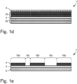
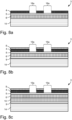
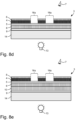
- Fig. 1a to Fig. 1g show schematic sectional views of decorative films 1.
- the decorative film 1 shown in particular for decorating a plastic molded part, comprises a colored lacquer layer 4, a colored lacquer layer 6 and a transparent laser protective lacquer layer 5, wherein the transparent laser protective lacquer layer 5 is arranged between the colored lacquer layer 4 and the colored lacquer layer 6.
- the colored lacquer layer 4 is the first colored lacquer layer and the colored lacquer layer 6 is the second colored lacquer layer in the above sense.
- the colored lacquer layer 4 represents the first colored lacquer layer and the colored lacquer layer 6 represents the second colored lacquer layer according to the above statements.
- the colored lacquer layer 4 is arranged on the side of the transparent laser protective lacquer layer 5 facing a viewer and the colored lacquer layer 6 is arranged on the side of the transparent laser protective lacquer layer 5 facing away from the viewer. It is thus provided that the colored lacquer layer 4 forms the side facing a viewer. It is also provided that the colored lacquer layer 6 is arranged below the transparent laser protective lacquer layer 5 and below the colored lacquer layer 4 in the viewing direction.
- a transparent laser protective lacquer layer 5 is understood to mean a transparent protective lacquer layer, in particular a transparent intermediate protective lacquer layer, which protects the colour lacquer layer 6, in particular the layers lying below the transparent intermediate protective lacquer layer as seen by an observer, from mechanical, physical and/or chemical environmental influences and/or which is designed in such a way that it continues to serve as a spacer or buffer layer for the ablating laser.
- the Fig. 1 shown transparent laser protective lacquer layer 5 is a transparent protective lacquer layer, in particular a transparent intermediate protective lacquer layer.
- the transparent laser protective lacquer layer 5 preferably has a layer thickness between 0.5 ⁇ m and 50 ⁇ m, preferably between 2.0 ⁇ m and 2.5 ⁇ m.
- Fig. 1a The transparent laser protective lacquer layer 5 shown has, for example, a layer thickness between 2.0 ⁇ m and 2.5 ⁇ m.
- the transparent laser protective lacquer layer 5 has a transmission, in particular in the wavelength range between 380 nm and 780 nm, of at least 25%, preferably of at least 75%, more preferably of at least 85%.
- Fig. 1a The transparent laser protective lacquer layer shown has, for example, a transmission of at least 75%, preferably of at least 85%.
- the transparent laser protective lacquer layer 5 has a transmission in the infrared range, preferably the near infrared range, more preferably in the wavelength range between 780 nm and 1400 nm, even more preferably for light of the wavelength of 1064 nm, of at least 25%, preferably of at least 75%, more preferably of at least 85%.
- the transparent laser protective lacquer layer 5 is heat-resistant, in particular up to a temperature of 250 °C, preferably up to 650 °C, more preferably up to 1000 °C.
- the transparent laser protective lacquer layer 5 diffusely scatters transmitted light, in particular light in the wavelength range between 380 nm and 780 nm, and/or the transparent laser protective lacquer layer 5 has a haze value of at most 50 haze units, preferably of at most 20 haze units.
- the haze value is preferably determined in haze units in transmission according to the ASTM D 1003 standard.
- the haze value is measured using the "BYK haze-gard i" measuring device from Byk-Gardener, Geretsried, Germany.
- the layer or film to be measured is preferably held in the open sample chamber of the measuring device and, in particular for the haze value, placed on the so-called "haze port" of the device, with the measurement advantageously being carried out using standard light D65.
- the result of the measurement is then preferably displayed on the screen of the measuring device.
- the haze value is advantageously given in percent (%). It is therefore possible that the unit of the haze value in this case is percent (%).
- the value range of the haze value is therefore preferably 0-100%. It is therefore possible that the haze units are percentage values or that the haze units represent percentage values.
- the maximum value is preferably 100%. Any values higher than 100% that may occur may, for example, be caused by additional scattered light effects and/or reflection effects during the measurement, particularly depending on the measuring principle used.
- Haze is preferably understood here as diffuse scattering, in particular large-angle scattering, which in particular leads to a reduction in image quality.
- Particles or inhomogeneities in the material preferably act as scattering centers, at which the light in particular is scattered in all spatial directions, with only a low scattering intensity being advantageously allocated to each solid angle.
- This in particular causes a reduction in contrast and/or a milky, cloudy appearance, with this effect preferably being referred to as haze or turbidity.
- the haze value is therefore preferably a measure of the turbidity of transparent samples, for example plastic layers or films.
- the ratio of the light deflected by the transparent laser protective lacquer layer 5 from the angle range of less than 2.5° from the direction of the incident light in transmission in relation to the total light transmitted by the transparent laser protective lacquer layer 5 is less than 0.5, preferably less than 0.2.
- the transparent laser protective lacquer layer 5 it is possible for the transparent laser protective lacquer layer 5 to deflect less than 50%, preferably less than 20%, of the transmitted light, in particular from the wavelength range between 380 nm and 780 nm, by more than 2.5° from the direction of the incident light beam.
- the transparent laser protective lacquer layer 5 has a milky, cloudy appearance and/or the transparent laser protective lacquer layer 5 deflects more than 30%, preferably more than 45%, more preferably more than 65%, of the transmitted light, in particular from the wavelength range between 380 nm and 780 nm, by more than 2.5° from the direction of the incident light beam.
- the transparent laser protective lacquer layer 5 deflects less than 30%, preferably less than 45%, more preferably less than 65%, of the transmitted light, in particular from the wavelength range between 380 nm and 780 nm, by less than 2.5° from the direction of the incident light beam.
- the ratio of the light deflected by the transparent laser protective lacquer layer 5 from the angular range of less than 2.5° from the direction of the incident light in transmission in relation to the total light transmitted by the transparent laser protective lacquer layer 5 is greater than 0.3, preferably greater than 0.45, more preferably greater than 0.65.
- the transparent laser protective lacquer layer 5 is colored, in particular for the transparent laser protective lacquer layer 5 to be colored using dyes and/or color pigments.
- the degree of pigmentation of the transparent laser protective lacquer layer 5 is preferably less than 15%, preferably less than 10%, more preferably less than 5%.
- the transparent laser protective lacquer layer 5 is colorless and/or clearly transparent and/or that the degree of pigmentation of the transparent laser protective lacquer layer 5 is 0%.
- the degree of pigmentation of the Fig. 1a the transparent laser protection lacquer layer 5 shown in Fig. 1a shown transparent laser protection lacquer layer 5 is in particular an unpigmented clear lacquer layer.
- the transparent laser protective lacquer layer 5 is preferably a layer of monomers, oligomers, polymers and/or copolymers, which preferably Polymethyl methacrylate (PMMA), polyester, polycarbonate (PC), polyamide (PA), polyurethane (PU) and/or polyvinyl chloride (PVC), more preferably PU and/or PVC. It is also possible that the transparent laser protective lacquer layer 5 comprises polyacrylate as a binder. For example, the Fig. 1a The transparent laser protection lacquer layer 5 shown contains polyacrylate as a binding agent.
- the transparent laser protective lacquer layer 5 comprises polyetherimides (PEI) and/or polysulfones, such as poly(arylethersulfone)s (PAES).
- PEI polyetherimides
- PAES poly(arylethersulfone)s
- the transparent laser protective lacquer layer 5 may harden or be hardened thermally and/or by high-energy radiation. Hardening preferably takes place before and/or after processing the decorative film or transfer film and/or application of the decorative film or transfer film to a substrate.
- the transparent laser protective lacquer layer 5 protects the colored lacquer layer 6, in particular the layers located below the transparent laser protective lacquer layer 5 as seen by an observer, from mechanical, physical and/or chemical environmental influences.
- the color lacquer layer 4 is preferably a layer made of polyethylene terephthalate (PET), PMMA, polyethylene naphthalate (PEN), PA and/or acrylonitrile-butadiene-styrene copolymer (ABS). It is also possible that the color lacquer layer 4 contains acrylate as a binder. For example, the Fig. 1a The color lacquer layer 4 shown contains acrylate as a binding agent.
- the color lacquer layer 4 has a layer thickness between 0.1 ⁇ m and 50 ⁇ m, preferably between 0.5 ⁇ m and 5.0 ⁇ m.
- Fig. 1a the color varnish layer shown has a layer thickness between 5.0 ⁇ m and 5.5 ⁇ m.
- the color lacquer layer 4 is preferably opaque and/or advantageously has a transmission, in particular in the wavelength range between 380 nm and 780 nm, of a maximum of 50%, preferably a maximum of 20%, more preferably a maximum of 5%.
- the Fig. 1a For example, the color lacquer layer 4 shown has a maximum transmission of 5%.
- the colored lacquer layer 4 is colored, in particular if the at least one colored lacquer layer 4 is colored by means of dyes and/or color pigments.
- the degree of pigmentation of the colored lacquer layer 4 is preferably between 5% and 35%, preferably between 20% and 25%.
- Fig. 1a The color lacquer layer 4 shown is colored, for example, by means of color pigments and further has, for example, a degree of pigmentation between 5% and 35%, preferably between 20% and 25%.
- the colored lacquer layer 4 is colored dark, in particular black, and/or that the colored lacquer layer 4 comprises light-absorbing particles, in particular soot.
- the color lacquer layer 6 is preferably made of PET, PMMA, PEN, PA and/or ABS and/or has acrylate as a binder.
- the Fig. 1a The color lacquer layer 6 shown contains, for example, acrylate as a binding agent.
- the color lacquer layer 6 preferably has a layer thickness between 0.1 ⁇ m and 50 ⁇ m, preferably between 1.0 ⁇ m and 5.0 ⁇ m.
- the Fig. 1a For example, the color lacquer layer 6 shown has a layer thickness between 6.0 ⁇ m and 7.0 ⁇ m.
- the colored lacquer layer 6 has a transmission, in particular in the wavelength range between 380 nm and 780 nm, of at least 10%. It is also advantageous that the colored lacquer layer 6 is transparent and/or that the colored lacquer layer 6 has a transmission, in particular in the wavelength range between 380 nm and 780 nm, of at least 25%, preferably of at least 75%, more preferably of at least 90%.
- the colored lacquer layer 6 has Fig. 1a
- the color lacquer layer shown has, for example, a transmission of at least 25%, preferably of at least 45%.
- the colored lacquer layer 6 is translucent, in particular translucent by means of a backlighting means, and/or if the colored lacquer layer 6 is designed such that more than 10%, preferably more than 25%, more preferably more than 75%, even more preferably more than 90% of the light emitted by a backlighting means arranged behind the colored lacquer layer 6 in the viewing direction is transmitted.
- the color lacquer layer 6 is as in Fig. 1a shown, formed over the entire surface, in particular the colored lacquer layer 6 takes up the entire surface when viewed perpendicular to the decorative film 1.
- the colored lacquer layer 6 diffusely scatters light, in particular light in the wavelength range between 380 nm and 780 nm, and/or that the colored lacquer layer 6 has a haze value of at least 50 haze units, preferably of at least 75 haze units.
- the colored lacquer layer 6 deflects more than 50% of the transmitted light, in particular from the wavelength range between 380 nm and 780 nm, by more than 2.5° from the direction of the incident light beam. In other words, the colored lacquer layer 6 deflects less than 50% of the transmitted light, in particular from the wavelength range between 380 nm and 780 nm, by less than 2.5° from the direction of the incident light beam. It is also advantageous if the colored lacquer layer 6 deflects more than 75%, preferably more than 85%, of the transmitted light, in particular from the wavelength range between 380 nm and 780 nm, by more than 2.5° from the direction of the incident light beam.
- the color lacquer layer 6 deflect less than 75%, preferably less than 85%, of the transmitted light, in particular from the wavelength range between 380 nm and 780 nm, by less than 2.5° from the direction of the incident light beam.
- the colored lacquer layer 6 forms a diffuser film and/or that the colored lacquer layer 6 is a diffuser film.
- Diffuser film is understood here to be a particularly self-supporting, dry layer that can be applied, for example, by means of lamination or similar processes.
- Such a diffuser film preferably represents an alternative to a second color varnish layer printed or cast using a wet process.
- the colored lacquer layer 6 is preferably also colored, in particular colored by means of dyes and/or colored pigments.
- the degree of pigmentation of the colored lacquer layer 6 is between 5% and 80%, preferably between 40% and 45%.
- the colour lacquer layer 6 shown is, for example, a layer coloured by means of colour pigments, the degree of pigmentation being, for example, between 40% and 45%.
- the color lacquer layer 6 or a layer adjacent to the second color lacquer layer 6 is designed as a light guide layer.
- This light guide layer preferably has a light coupling surface on one of its end faces, in particular into which light from a light source is radiated into the light guide layer. It is possible for this light source to be arranged in such a way that it is not arranged below the decorative film 1 in the viewing direction, but rather laterally offset from it, for example. It is also useful if the light guide layer has light coupling surfaces, which have a surface structure, for example, at least in certain areas on its surface facing the transparent laser protection lacquer layer 5. In this case it is possible that the light output surfaces are designed in such a way that diffusely scattered light is output preferably distributed over the light output surfaces.
- a fluorescent dye preferably in the form of dye particles
- the colored lacquer layer 6 which in the design as a light guide layer consists of polycarbonate or PVC, for example. It is thus possible for the colored lacquer layer 6 to have a fluorescent dye, preferably in the form of dye particles, particularly in the area of the light output surfaces.
- the dye particles are excited to fluoresce and emit fluorescent light isotropically, i.e. also in the direction of the light guide layer. This makes it possible to determine the color of the output light when the light source is switched on, depending on the fluorescent dye in the plastic material.
- the colored lacquer layer 6 in the embodiment as a light guide layer is designed in particular as a self-supporting, dry layer, which is applied for example by means of gluing or lamination or similar methods. Furthermore, it is also possible that the colored lacquer layer 6 in the embodiment as a light guide layer is printed or cast using a wet process.
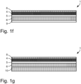
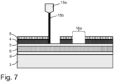
- the decorative film 1 shown in particular for decorating a plastic molded part, comprises a colored lacquer layer 4, a colored lacquer layer 6, a protective lacquer layer 8 and a transparent laser protective lacquer layer 5, wherein the transparent laser protection lacquer layer 5 is arranged between the color lacquer layer 4 and the color lacquer layer 6.
- the protective lacquer layer 8 is arranged above the colored lacquer layer 4.
- the colored lacquer layer 4 forms the side of the decorative film 1 facing a viewer.
- the protective lacquer layer 8 is thus arranged on the side of the decorative film 1 facing the viewer.
- the terms below and/or above are understood to mean in particular the arrangement of layers in relation to another layer when viewed by an observer from one viewing direction. It is therefore useful if the terms below and/or above represent a reference system.
- the color lacquer layer 6 is arranged below the transparent laser protection lacquer layer 5 in the viewing direction.
- the protective lacquer layer 8 forms the layer facing the viewer.
- the protective lacquer layer 8 is, as in Fig. 1b shown, arranged in the viewing direction above the color lacquer layer 4, the color lacquer layer 6 and the transparent laser protective lacquer layer 5.
- the protective lacquer layer 8 preferably completely covers the colored lacquer layer 4 when viewed perpendicular to a plane spanned by the colored lacquer layer 4, the colored lacquer layer 6 and/or the transparent laser protective lacquer layer 5. However, it is also possible that the protective lacquer layer 8 only covers the colour lacquer layer 4 in certain areas.
- the protective lacquer layer 8 advantageously protects the layers arranged below the protective lacquer layer 8 in the viewing direction from mechanical, physical and/or chemical environmental influences, in particular at least in those areas in which the protective lacquer layer 8 is not later removed or applied again.
- the protective lacquer layer 8 is expediently transparent and/or the protective lacquer layer 8 has a transmission, in particular in the wavelength range between 380 nm and 780 nm, of at least 25%, preferably of at least 35%, more preferably of at least 85%.
- the Fig. 1b shown protective lacquer layer 8 is a transparent protective lacquer layer 8 which, for example, has a transmission of at least 85%.
- the layer thickness of the protective lacquer layer 8 is preferably between 0.5 ⁇ m and 50 ⁇ m, more preferably between 4.0 ⁇ m and 4.5 ⁇ m.
- Fig. 1b The protective lacquer layer 8 shown, for example, has a layer thickness between 4.0 ⁇ m and 4.5 ⁇ m.
- the protective lacquer layer 8 is preferably a layer of monomers, oligomers, polymers and/or copolymers, preferably comprising polymethyl methacrylate (PMMA), polyester, polycarbonate (PC), polyamide (PA), polyurethanes (PU) and/or polyvinyl chloride (PVC), more preferably comprising PU and/or PVC. It is also possible for the protective lacquer layer 8 to have polyacrylate as a binder.
- the protective lacquer layer 8 comprises polyetherimides (PEI) and/or polysulfones, such as poly(arylethersulfone)s (PAES).
- PEI polyetherimides
- PAES poly(arylethersulfone)s
- the protective lacquer layer 8 may harden or be hardened thermally and/or by high-energy radiation. Hardening preferably takes place before and/or after processing the decorative film or transfer film and/or application of the decorative film or transfer film to a substrate.
- the protective lacquer layer shown contains, for example, acrylate, in particular reactively curing acrylates, as a binder, with curing preferably taking place thermally and/or by means of UV radiation.
- the protective lacquer layer 8 may be colored, in particular for the protective lacquer layer to be colored using dyes and/or color pigments.
- the degree of pigmentation of the protective lacquer layer 8 is preferably less than 15%, preferably less than 10%, more preferably less than 5%.
- the protective lacquer layer 8 is colorless and/or clearly transparent and/or that the degree of pigmentation of the protective lacquer layer is 0%.
- the protective lacquer layer 8 is clear, in particular the protective lacquer layer 8 directs transmitted light, in particular light in the Wavelength range between 380 nm and 780 nm, by less than 8%, preferably by less than 4%, due to scattering.
- the protective lacquer layer 8 shown is, for example, an unpigmented clear lacquer layer.
- Decorative film 1 shown corresponds to the one in Fig. 1b shown decorative film with the difference that the colored lacquer layer 4 is formed as a metal layer 4a and the colored lacquer layer 6 is formed as a metal layer 6a.
- the metal layer 4a is an optically dense metal layer, which preferably has a lower transmission compared to the metal layer 6a. It is equally advantageous if the metal layer 6a is an optically thin metal layer, which preferably has a greater transmission compared to the metal layer 4a.
- the metal layer 4a has a transmission, in particular in the wavelength range between 380 nm and 780 nm, of a maximum of 30%, preferably a maximum of 10%, more preferably a maximum of 5%.
- the metal layer 6a preferably has a transmission, in particular in the wavelength range between 380 nm and 780 nm, of more than 10%. preferably more than 25%, more preferably more than 50%, even more preferably more than 75%, and even more preferably more than 90%.
- the layer thickness of the first metal layer 4a is between 10 nm and 1 ⁇ m, preferably between 20 nm and 300 nm.
- the layer thickness of the second metal layer 6a is preferably between 1 nm and 500 nm, preferably between 10 nm and 80 nm.
- the transmission values are determined in particular in the wavelength range between 380 nm and 780 nm, i.e. in the wavelength range visible to the human eye.
- the optical density of a metal layer depends, among other things, on the layer thickness used and the metal used.
- the metal layer 4a and/or the metal layer 6a can be made of aluminium, cobalt, copper, gold, iron, chromium, nickel, silver, platinum, palladium and/or titanium or alloys thereof. Aluminium is preferably used for the optically denser metal layer 4a due to its low penetration depth for light from the wavelength range visible to the human eye and gold, copper, chromium, silver and/or iron are used for the optically thinner metal layer 6a due to their large penetration depth for light from the wavelength range visible to the human eye.
- Decorative film 1 shown corresponds to the one in Fig. 1b shown decorative film 1 with the difference that the colored lacquer layer 4b and the colored lacquer layer 6b are multi-layered.
- the colored lacquer layer 4b is shown to be formed from two partial layers, wherein the two partial layers each have a layer thickness of between 0.1 ⁇ m and 50 ⁇ m, preferably between 0.5 ⁇ m and 5.0 ⁇ m.
- the color lacquer layer 6b is also formed from two partial layers, wherein the two partial layers preferably each have a layer thickness between 0.1 ⁇ m and 50 ⁇ m, more preferably between 1.0 ⁇ m and 5.0 ⁇ m.
- the two sub-layers each have different colors, in particular from the RGB color space or the CMYK color space.
- Decorative film 1 shown corresponds to the one in Fig. 1a shown decorative film 1 with the difference that the colored lacquer layer 4 is formed in regions.
- the color lacquer layer 4 is present in the areas 16b and not present in the areas 16c.
- Such a color lacquer layer 4 formed in regions can be produced, for example, by means of printing processes such as letterpress printing, in particular flexographic printing, planographic printing, in particular offset printing, gravure printing, inkjet printing, and/or through-printing, in particular screen printing. Furthermore, it is also possible, in particular if the color lacquer layer 4 is formed as a metal layer 4a, for it to be produced by means of metallization processes such as CVD processes (chemical vapor deposition) and/or PVD processes ( physical vapor deposition), preferably using a mask, in particular a photolithographic mask.
- CVD processes chemical vapor deposition
- PVD processes physical vapor deposition
- the term “region” is understood to mean in particular a defined area of a layer or ply which, when viewed perpendicular to a plane spanned by the decorative film 1, in particular by the colored lacquer layer 4, the transparent laser protection lacquer layer 5 and/or the colored lacquer layer 6.
- the colored lacquer layer 4 has regions 16b in which the colored lacquer layer 4 is present and regions 16c in which the colored lacquer layer 4 is not present, with each of the regions 16b, 16c each occupying a defined area when viewed perpendicular to a plane spanned by the transparent laser protection lacquer layer 5.
- the in Fig. 1f The decorative foil shown corresponds to the one in Fig. 1b shown decorative film 1 with the difference that the decorative film 1 further comprises an adhesive layer 9.
- the adhesive layer 9 is shown arranged on the side of the colored lacquer layer 6 facing away from the transparent laser protection lacquer layer 5.
- the adhesive layer 9 is arranged on the side of the colored lacquer layer 4 and/or the protective lacquer layer 8 facing away from the transparent laser protective lacquer layer.
- the adhesive layer 9 it is thus possible for the adhesive layer 9 to form the layer or surface of the decorative film 1 facing towards and/or away from a viewer and/or to lie or be arranged above the colored lacquer layer 4, the colored lacquer layer 6 and/or the transparent laser protective lacquer layer 5 in the viewing direction and/or for the adhesive layer 9 to lie or be arranged below the colored lacquer layer 4, the colored lacquer layer 6 and/or the transparent laser protective lacquer layer 5 in the viewing direction.
- the adhesive layer 9 covers the colored lacquer layer 4 or the colored lacquer layer 6 in regions or completely when viewed perpendicular to a plane spanned by the colored lacquer layer 4, the colored lacquer layer 6 and/or the transparent laser protection lacquer layer 5.
- the decorative film 1 makes it possible for the decorative film 1 to be applied to a plastic molded part, in particular to be applied firmly, in particular to be applied in such a way that the decorative film 1 is firmly bonded to the plastic molded part. is connected.
- the term "firmly connected” is preferably understood to mean a permanent connection between two elements, so that they can no longer be mechanically separated without damaging at least one of the elements.
- the decorative film 1 and a plastic molded part are firmly connected if there is a permanent connection between these two elements and the decorative film 1 and/or the plastic molded part cannot be separated without damaging one of the two elements.
- the adhesive layer 9 expediently has a layer thickness between 0.1 ⁇ m and 50 ⁇ m, preferably between 0.5 ⁇ m and 7 ⁇ m, more preferably between 2.5 ⁇ m and 3.0 ⁇ m.
- Fig. 1f The adhesive layer 9 shown, for example, has a layer thickness between 2.5 ⁇ m and 3.0 ⁇ m.
- the adhesive layer 9 is transparent and/or has a transmission, in particular in the wavelength range between 380 nm and 780 nm, of at least 45%, preferably of at least 65%, more preferably of at least 95%.
- the Fig. 1f For example, the adhesive layer 9 shown has a transmission of at least 45%.
- the adhesive layer 9 consists of a material which is clearly transparent after application to the plastic molded part, in particular the adhesive layer 9 consists of a material which, after application to the plastic molded part, deflects light in the wavelength range between 380 nm and 780 nm by less than 8%, preferably by less than 4%, through scattering.
- the adhesive layer 9 is preferably a layer of polymers and/or copolymers, in particular comprising PMMA, polyester, PU or PVC. It is also possible for the adhesive layer 9 to contain acrylate as a binder. For example, the Fig. 1f The adhesive layer 9 shown contains acrylate as a binding agent.
- the adhesive layer 9 is colored, in particular that the adhesive layer 9 is colored by means of dyes and/or color pigments.
- the degree of pigmentation of the adhesive layer 9 is advantageously between 5% and 50%, preferably between 30% and 35%.
- the Fig. 1f The adhesive layer 9 shown has a pigmentation level of between 30% and 35%.
- the adhesive layer 9 is colorless and/or clearly transparent and/or that the degree of pigmentation of the adhesive layer 9 is 0%.
- the decorative film 1 shown in particular for decorating a plastic molded part, comprises a colored lacquer layer 4, a colored lacquer layer 6, a protective lacquer layer 8, an electrical functional layer 10 with an electrical functional structure and a transparent laser protective lacquer layer 5, wherein the transparent laser protective lacquer layer 5 is arranged between the colored lacquer layer 4 and the colored lacquer layer 6.
- the in Fig. 1g Decorative film 1 shown corresponds to the one in Fig. 1b shown decorative film 1 with the difference that the decorative film 1 further has an electrical functional layer 10 with at least one electrical functional structure.
- a touch sensor field forms the electrical functional structure, which provides a touch field functionality.
- a touch sensor field is understood here in particular to mean a touch-sensitive sensor that enables the control of an electrical functional element, for example a PDA or a control element marked with a symbol or lettering, for example a motor vehicle.
- a touch sensor field is also understood in particular to mean a multi-touch sensor field that can process several simultaneous touches.
- the at least one electrical functional structure forms a capacitive sensor field.
- the at least one electrical functional structure forms a resistive or inductive sensor field.
- the at least one electrical functional structure additionally has further functional elements, such as electrical supply lines, electrical and/or electronic components, such as integrated circuits.
- the at least one electrical functional structure is designed in one layer or in multiple layers. It is also possible for the at least one electrical functional structure to have a reinforcing layer at least in some areas, which is applied, for example, by means of electroplating and/or by printing with metal pigment layers and/or other conductive layers such as carbon.
- the decorative film 1 forms a touch sensor and/or that the decorative film 1 is a touch sensor.
- all layers arranged below the transparent laser protective lacquer layer 5 in the viewing direction are transparent, in particular if all layers arranged below the transparent laser protective lacquer layer 5 have a transmission of at least 25%, preferably of at least 45%.
- Fig. 2 shows a schematic of a diffusely scattering layer.
- the diffusely scattering layer can be, for example, the colored lacquer layer 6, which scatters transmitted light diffusely, preferably in a large solid angle range, more preferably in all spatial directions, so that light, in particular from a point light source, is scattered homogeneously, so that the colored lacquer layer 6 appears homogeneously illuminated to a viewer 7, in particular despite illumination with a point light source. It is thus possible for the colored lacquer layer 6 to form a diffuser film and/or for the colored lacquer layer 6 to be a diffuser film.
- incident light 17a is transmitted and scattered in particular by the color lacquer layer 6.
- light in the wavelength range between 380 nm and 780 nm is diffusely scattered by the color lacquer layer 6, and/or the color lacquer layer 6 preferably has a haze value of at least 50 haze units, preferably of at least 75 haze units.
- the colored lacquer layer 6 scatters the transmitted light over a large angular range, in particular a solid angle range. It is thus possible for the light 17b scattered by the colored lacquer layer 6 to be scattered over an angular range, in particular over a solid angle range, of at least 120°, preferably of at least 150°, even more preferably of at least 180°. In other words, it is possible for the colored lacquer layer 6 to scatter the transmitted light, in particular uniformly, spherically, preferably hemispherically, with preferably identical surface areas of the sphere, preferably the hemisphere, receiving essentially the same light proportion of the scattered light.
- the colored lacquer layer 6 deflects more than 50% of the transmitted light, in particular from the wavelength range between 380 nm and 780 nm, by more than 2.5° from the direction of the incident light beam. It is also possible, as already explained above, for the colored lacquer layer 6 to deflect more than 75%, preferably more than 85%, of the transmitted light, in particular from the wavelength range between 380 nm and 780 nm, by more than 2.5° from the direction of the incident light beam.
- the one diffusely scattering layer such as the colored lacquer layer 6 here
- a diffusely scattering layer preferably creates a uniformly illuminated surface for a viewer, even if, for example, several point light sources, such as LEDs, are arranged behind the diffusely scattering layer, such as the colored lacquer layer 6 here.
- Fig. 3 shows a schematic sectional view of a transfer film 2.
- the transfer film in particular hot stamping film and/or in-mold film, comprises a carrier film 11 and a decorative film 1 that can be detached from the carrier film 11.
- a carrier film 11 for example, hot stamping film and/or in-mold film
- a decorative film 1 that can be detached from the carrier film 11.
- the transfer film 2 comprises a carrier film 11 and in particular a transfer layer that can be detached from the carrier film 11, wherein the decorative film 1 preferably forms the transfer layer of the transfer film 2 and wherein the transfer layer is arranged on the carrier film 11 and can be detached from the carrier film.
- the transfer film 2 also includes Fig. 3 can be seen, advantageously further a release layer 12, which is arranged in particular between the carrier film 11 and the removable decorative film 1.
- the release layer 12 preferably has a layer thickness between 0.01 ⁇ m and 10 ⁇ m, preferably between 0.1 ⁇ m and 5 ⁇ m. Furthermore, the release layer 12 consists in particular of waxes, polyethylene (PE), polypropylene (PP), cellulose derivatives and/or poly(organo)siloxanes.
- the release layer 12 consists in particular of waxes, polyethylene (PE), polypropylene (PP), cellulose derivatives and/or poly(organo)siloxanes.
- the carrier film 11 is expediently a transparent carrier film, in particular made of PET, PMMA, PC, ABS or PU, and/or the carrier film 11 has a layer thickness between 2 ⁇ m and 250 ⁇ m, preferably between 20 ⁇ m and 125 ⁇ m.
- Such a transfer film 2 is also used in particular as a hot stamping film and/or in-mold film, in particular as an in-mold decoration film, insert molding film, in-mold labeling film and/or print mold design film.
- the transfer film 2 is used as a hot stamping film, wherein in particular the decorative film 1 is transferred to a target substrate, such as a plastic molded part, by means of a heated embossing stamp which exerts pressure on the transfer film 2 for a certain period of time.
- the carrier film 11 is then preferably removed.
- the transfer film 2 can be used as an in-mold film, in particular as an in-mold decoration film, insert molding film, in-mold labeling film and/or print mold design film, wherein the transfer film 2 is placed in an injection mold and then, preferably after the injection mold has been closed, the transfer film 2 is back-injected with a plastic compound in such a way that the decorative film bonds firmly to the plastic compound.
- the carrier film 11 is then preferably removed.
- Fig. 4a to Fig. 4d show schematically process steps for producing a transfer film 2.
- carrier film 11 is first provided. Then, optionally, a release layer 12 is applied to the carrier film 11.
- the release layer 12 is preferably applied by means of a printing process or by means of a vapor deposition process.
- the colored lacquer layer 4 is applied. With regard to the design of the colored lacquer layer 4, reference is made to the above statements.
- the colored lacquer layer 4 is preferably applied using a printing process and/or metallization process. With regard to possible printing processes and/or metallization processes, reference is also made to the above statements.
- a further step as in Fig.
- the transparent laser protective lacquer layer 5 is applied, in particular by means of a printing process.
- the transparent laser protective lacquer layer 5 is applied in a further step, as in Fig. 4d shown, the color lacquer layer 6 is applied.
- the application of the color lacquer layer 6 is carried out in particular by means of printing processes, metallization processes and/or hot or cold transfer processes. Again, reference is made to the above statements with regard to the printing, metallization and transfer processes.
- an adhesive layer 9 is applied, for example by means of a printing process.
- the protective lacquer layer 8 shown can be additionally applied before the application of the first colored lacquer layer 4, preferably by means of a printing process or a casting process.
- the applied layers are pre-cured and/or hardened thermally and/or by means of UV radiation.
- the layers, in particular the colored lacquer layer 4, the transparent laser protective lacquer layer 5 and/or the colored lacquer layer 6, are applied to one another directly, i.e. preferably without further layers being arranged between the layers, in particular between the colored lacquer layer 4, the transparent laser protective lacquer layer 5 and/or the colored lacquer layer 6, in accordance with the steps set out above.
- the decorative film 1 which can be detached from the carrier film 11 to comprise the colored lacquer layer 4, the colored lacquer layer 6 and the transparent laser protective lacquer layer 5, with the transparent laser protective lacquer layer 5 being arranged between the colored lacquer layer 4 and the colored lacquer layer 6.
- Fig. 5a to Fig. 5c show schematic process steps for decorating a plastic molded part 3.
- a decorative film 1 is provided, wherein the decorative film 1 comprises a colored lacquer layer 4, a colored lacquer layer 6 and a transparent laser protection lacquer layer 5, and wherein the transparent laser protection lacquer layer 5 is arranged between the colored lacquer layer 4 and the colored lacquer layer 6.
- the decorative film 1 as in Fig. 5b shown, applied to a plastic molded part 3.
- the decorative film is preferably applied using hot or cold transfer methods, more preferably using hot stamping and/or in-mold methods.
- a further step which is described in Fig. 5c is shown, which, in particular, a The color lacquer layer 4 facing the viewer is removed in the areas 16a by means of a laser.
- Removing a layer here means the partial and/or complete removal of a layer, in particular by means of laser cutting and/or laser ablation. If, for example, a layer is removed in an area, the corresponding layer in this area has been partially and/or completely removed. The removal is preferably carried out by means of laser cutting and/or laser ablation. Removing also means the partial and/or complete removal of a layer, in particular by means of mechanical or precision engineering methods, for example by means of milling and/or grinding and/or drilling.
- step b) the decorative film 1 is applied to the plastic molded part 3 in such a way that the colored lacquer layer 4 forms the side facing the viewer 7 and the colored lacquer layer 6 forms the side facing away from the viewer.
- the areas 16a form decorative elements, such as symbols or lettering. It is also possible for areas 16a to represent a logo and/or a symbol and/or a pattern and/or an alphanumeric character.
- the areas 16a, when viewed perpendicular to the decorative film 1 and/or the plastic molded part 3, have a line thickness of at least 50 ⁇ m, preferably at least 100 ⁇ m, and/or if the regions 16a, when viewed perpendicular to the decorative film 1 and/or the plastic molded part 3, have a line thickness of a maximum of 2 mm, preferably a maximum of 1 mm, more preferably a maximum of 0.5 mm.
- step c) the colored lacquer layer 4 in the areas 16a is removed according to the invention by means of the laser in such a way that the transparent laser protective lacquer layer 5 is exposed. It is thus possible that in step c) the colored lacquer layer 4 is completely removed in the areas 16a.
- the colored lacquer layer 4 is removed in the regions 16a by means of a laser in such a way that the layer thickness of the transparent laser protective lacquer layer 5 in the regions 16a in which the colored lacquer layer 4 was removed by means of the laser essentially corresponds to the layer thickness of the transparent laser protective lacquer layer 5 in those regions in which the colored lacquer layer 4 was not removed by means of the laser.
- any slight superficial damage to the transparent laser protective lacquer layer 5 is acceptable, preferably as long as the total thickness of the transparent laser protective lacquer layer 5 is not reduced by more than 50%, preferably by no more than 30%.
- the transparent laser protective lacquer layer 5 is designed in such a way that the layer thickness of the transparent laser protective lacquer layer 5 in the areas 16a in which the color lacquer layer 4 is removed by means of a laser in comparison to those areas in in which the colored lacquer layer 4 is not removed by means of the laser, is reduced by less than 25%, preferably by less than 15%, more preferably by less than 5%.
- the transparent laser protective lacquer layer 5 fulfills its protective function against environmental influences for the underlying layers and, on the other hand, that the transparent laser protective lacquer layer 5 also fulfills or has fulfilled its function as a spacer or buffer layer.
- step b) the decorative film 1 is applied by means of transfer processes, in particular hot and/or cold transfer processes, such as hot stamping, in-mold decoration, insert molding, print mold design, in-mold labeling, lamination and/or gluing.
- transfer processes in particular hot and/or cold transfer processes, such as hot stamping, in-mold decoration, insert molding, print mold design, in-mold labeling, lamination and/or gluing.
- Fig. 6a to Fig. 6c show schematic process steps for decorating a plastic molded part 3.
- a transfer film 2 comprising a decorative film 1
- the decorative film 1 comprises a protective lacquer layer 8, a colored lacquer layer 4, a transparent laser protective lacquer layer 5, a colored lacquer layer 6 and an adhesive layer 9 and wherein the transparent laser protective lacquer layer 5 is arranged between the colored lacquer layer 4 and the colored lacquer layer 6.
- the decorative film 1 is applied to the plastic molded part 3.
- Transfer processes in particular hot and/or cold transfer processes, such as hot stamping, in-mold decoration, insert molding, print mold design, in-mold labeling, laminating and/or gluing, are preferably used to apply the decorative film 1.
- hot and/or cold transfer processes such as hot stamping, in-mold decoration, insert molding, print mold design, in-mold labeling, laminating and/or gluing
- a step shown in Fig. 6c In the step shown, at least the color lacquer layer 4 in the areas 16a is then removed by means of a laser. As in Fig. 6c As shown, the color lacquer layer 4 is arranged on the side of the plastic molded part 3 facing the viewer.
- the protective lacquer layer 8 arranged above the at least one first color lacquer layer 4 in the viewing direction is completely removed.
- Partially removed is preferably understood here to mean that the partially removed layer is changed or destroyed in such a way that it no longer fulfills its predetermined properties.
- a partially removed protective lacquer layer 8 no longer fulfills its predetermined property of protecting the layer arranged underneath from chemical, physical and/or mechanical environmental influences.
- Completely removed is preferably understood here to mean that the completely removed layers in the corresponding areas are removed and/or ablated and/or burned and/or vaporized without leaving any residue. If, for example, the colored lacquer layer 4 is completely removed in the areas 16a, in particular by means of laser cutting and/or laser ablation, the colored lacquer layer 4 in the areas 16a is removed without leaving any residue.
- the protective lacquer layer 8 arranged above the at least one first colored lacquer layer 4 in the viewing direction is removed in such a way that layers arranged below the protective lacquer layer 8 in the areas 16a, in particular the transparent laser protective lacquer layer 5 and/or the colored lacquer layer 6, are no longer protected from chemical, physical and/or mechanical environmental influences.
- the transparent laser protective lacquer layer 5 and/or the colored lacquer layer 6 are exposed to chemical, mechanical and/or physical environmental influences, so that the transparent laser protective lacquer layer 5 now fulfills the function of protecting the layer arranged below it.
- step c) in the regions 16a all layers arranged above the transparent laser protective lacquer layer 5 in the viewing direction are completely removed.
- an electrical functional layer with an electrical functional structure is arranged on the side of the color lacquer layer 6 facing away from the viewer, wherein the electrical functional structure forms a touch sensor field which provides a touch field functionality.
- the electrical functional layer with the electrical functional structure is arranged between the decorative film 1 and the plastic molded part 3.
- the electrical functional layer is arranged on the side of the colored lacquer layer 6 facing away from the transparent laser protection lacquer layer 5.
- the electrical functional layer with the electrical functional structure is firmly connected to the decorative film 1 and the plastic molded part 3.
- a backlighting device in particular comprising organic light-emitting diodes (OLED), inorganic light-emitting diodes (LED), microLEDs (mLED) and/or quantum dot light-emitting diodes (QLED), to be arranged preferably on the side of the plastic molded part 3 facing away from the decorative film 1.
- OLED organic light-emitting diodes
- LED inorganic light-emitting diodes
- mLED microLEDs
- QLED quantum dot light-emitting diodes
- the backlighting device may alternatively or additionally also comprise incandescent lamps, halogen lamps, gas discharge lamps and/or fluorescent lamps, in particular induction lamps.
- the backlighting device comprises lasers and/or chemical-physical illuminants, such as fluorescent paints or glow sticks.
- plastic molded part 3 in particular after the above steps for decorating a plastic molded part, 3 further steps are carried out, in particular for Further processing of the plastic molded part 3 can be carried out.
- the plastic molded part 3, in particular the plastic molded part 3 decorated with the decorative film 1 is further processed with one of the further steps selected from: painting with further layers, PU flooding, over-spraying or coating with another plastic component, milling, punching, deep drawing, polishing and/or embossing.
- Fig. 7 shows schematically a process step which is carried out during the process for decorating a plastic molded part 3.
- the method step shown is a detailed view of the above-mentioned step of removing at least the colored lacquer layer 4 in the regions 16a by means of a laser 15a.
- the colored lacquer layer 4 is removed by means of a laser 15a. Furthermore, the protective lacquer layer 8 arranged on the colored lacquer layer 4 and forming the surface of the plastic molded part 3 is also completely removed, as explained above.
- a laser 15a with a beam diameter at the focal point of at least 50 ⁇ m, preferably at least 100 ⁇ m, is used.
- a laser 15a in particular a fiber laser, is used, wherein the laser 15a emits coherent light from the infrared range, preferably the near infrared range, more preferably light from the Wavelength range between 780 nm and 1400 nm, more preferably light of wavelength 1064 nm, is emitted.
- the laser power is between 0.05 W and 100 W, preferably between 1 W and 20 W, more preferably between 5 W and 10 W.
- the laser beam 15b is guided along the regions 16a by means of deflectable mirrors, in particular by means of a laser scanning module.
- the laser 15a is operated with a writing speed of maximum 3000 mm/s, preferably with a writing speed between 500 mm/s and 2500 mm/s, and/or the laser 15a is operated with a pulse frequency between 1 Hz and 1000 kHz, preferably between 1 kHz and 200 kHz.
- the laser 15a it is also possible for the laser 15a to be operated continuously.
- a pulsed laser is preferably used, since this reduces the thermal load on the plastic molded part 3 in particular compared to a continuously operated laser.
- the parameters of the laser 15a are selected in particular depending on the layers 4, 8 to be removed as well as the layers 5, 6, 9, 3 that are not to be removed. In particular, the parameters are selected depending on the layer thicknesses and the material of the layers 4, 8 to be removed and/or the layers 5, 6, 9, 3 that are not to be removed.
- the parameters of the laser 15a are also influenced by the material of the plastic molded part 3, since this is particularly dependent on the material removed by the laser. 15a or laser beam 15b. In order to prevent deformation of the plastic molded part 3 in particular, the material of the plastic molded part 3 must therefore also be taken into account when selecting the laser parameters.
- the penetration depth of the laser 15a or the laser beam 15b is influenced in particular by the parameters writing speed, pulse frequency and laser power.
- the laser parameters are advantageously also selected depending on the design of the areas 16a to be removed.
- the layout, layout size, line thickness and filling effects are to be mentioned here. These include, for example, the number and laser direction of fillings, repetitions of outlines and fillings and the order of the individual components of the layout.
- Fig. 8a to Fig. 8e show schematic sectional views of a plastic molded part 3.
- the in Fig. 8a The plastic molded part 3 shown comprises a decorative film 1.
- the decorative film 1 comprises the colored lacquer layer 4, the colored lacquer layer 6 and the transparent laser protective lacquer layer 5, wherein the transparent laser protective lacquer layer 5 is between the colored lacquer layer 4 and the Colored lacquer layer 6 is arranged. Furthermore, the colored lacquer layer 4 facing a viewer is removed in the areas 16a by means of a laser.
- the design of the layers 4, 5 and 6 reference is made to the above explanations.
- the plastic molded part as in Fig. 8a shown, has a layer of a thermoplastic material 14, which is arranged on the side of the colored lacquer layer 6 facing away from the viewer. It is thus possible for the at least one layer of a thermoplastic material 14 to be arranged on the colored lacquer layer 6 facing away from the viewer.
- the regions 16a preferably have a line thickness of at least 50 ⁇ m, preferably at least 100 ⁇ m, when viewed perpendicular to the decorative film 1. However, it is also possible for the regions 16a to have a line thickness of a maximum of 2 mm, preferably a maximum of 1 mm, more preferably a maximum of 0.5 mm, when viewed perpendicular to the decorative film 1.
- the plastic molded part 3 it is possible for the plastic molded part 3 to have a layer thickness between 0.5 mm and 10 mm, preferably between 0.8 mm and 5 mm.
- the layer of a thermoplastic material 14 is transparent, in particular the layer of a thermoplastic material Material 14 has a transparency between 5% and 98%, particularly in the wavelength range between 380 nm and 780 nm.
- the layer of a thermoplastic material 14 is preferably formed from one of the following materials: ABS, PC, ABS/PC, PC/ABS, PMMA, polypropylene (PP), PA, thermoplastic polyurethane (TPU).
- the layer made of a thermoplastic material 14 is colored, in particular that the layer made of a thermoplastic material 14 is colored by means of dyes and/or color pigments.
- the degree of pigmentation of the layer made of a thermoplastic material 14 is preferably less than 15%, preferably less than 10%, more preferably less than 5%.
- the plastic molded part 3 shown corresponds to the one in Fig. 8a shown plastic molded part 3 with the difference that the plastic molded part 3, in particular the decorative film 1 encompassed by the plastic molded part 3, further comprises the protective lacquer layer 8 and the adhesive layer 9, wherein the protective lacquer layer 8 is completely removed in the areas 16a, as explained above.
- the protective lacquer layer 8 and the adhesive layer 9 reference is made here to the above statements.
- the plastic molded part 3 shown corresponds to the one in Fig. 8b shown plastic molded part 3 with the difference that the plastic molded part 3, in particular the decorative film 1 encompassed by the plastic molded part 3, further comprises the electrical functional layer 10 with an electrical functional structure on the color lacquer layer 6 facing away from a viewer, wherein the Functional structure forms a touch sensor field which provides a touch field functionality.
- the functional layer 10 with the electrical functional structure is arranged between the decorative film 1 and the layer of thermoplastic material 14.
- the functional layer 10 is thus preferably arranged on the side of the colored lacquer layer 6 facing away from the transparent laser protection lacquer layer 5.
- Fig. 8c shown plastic molded part 3, in particular the plastic molded part 3 decorated with the decorative film 1, for example a touch sensor.
- the Fig. 8d Plastic molded part 3 shown also corresponds to the one in Fig. 8b shown plastic molded part with the difference that the plastic molded part 3 further comprises a backlighting device 13, in particular comprising organic light-emitting diodes (OLED), inorganic light-emitting diodes (LED), microLEDs (mLED) and/or quantum dot light-emitting diodes (QLED), wherein the backlighting device 13 is preferably arranged on the side of the layer of thermoplastic material 14 facing away from the decorative film 1.
- OLED organic light-emitting diodes
- LED inorganic light-emitting diodes
- mLED microLEDs
- QLED quantum dot light-emitting diodes
- the plastic molded part 3 shown corresponds to the one in Fig. 8c shown plastic molding with the difference that the plastic molding 3 continues, as in Fig. 8d shown plastic molded part 3, has a backlighting device 13, wherein the backlighting device 13 is preferably arranged on the side of the layer of thermoplastic material 14 facing away from the decorative film 1.
- Fig. 9 shows schematically a plan view of a decorative film 1 and/or of a plastic molded part 3 which comprises a decorative film 1.
- the decorative film 1 and/or the plastic molded part 3 comprising the decorative film 1 has areas 16a in which at least the colored lacquer layer 4, 4a, 4b has been removed by means of a laser.
- the areas 16a form, as in Fig. 9 shown, decorative elements, such as symbols or lettering.
- the areas 16a form, as shown in Fig. 9 shown, symbols.
- the areas represent patterns and/or logos and/or alphanumeric characters.
- the Fig. 9 represents, on the one hand, the top view of a decorative film 1, in which the color lacquer layer 4, 4a, 4b facing a viewer is removed, in particular completely removed, in the areas 16a, so that the transparent laser protection lacquer layer 5 is exposed, in particular in the areas 16a. Furthermore, the Fig. 9 also the top view of a plastic molded part 3, which comprises a decorative film 1, which, as explained above, is also applied to the Plastic molding is applied and is designed according to the above statements. It can therefore be Fig. 9 It can be both a top view of a decorative film 1 and a top view of a plastic molded part 3 decorated with a decorative film 1.
Landscapes
- Laminated Bodies (AREA)
- Decoration By Transfer Pictures (AREA)
- Thermal Transfer Or Thermal Recording In General (AREA)
Applications Claiming Priority (2)
| Application Number | Priority Date | Filing Date | Title |
|---|---|---|---|
| DE102018123473.2A DE102018123473A1 (de) | 2018-09-24 | 2018-09-24 | Dekorfolie, Transferfolie, Verwendung einer Transferfolie, Verfahren zur Herstellung einer Transferfolie, Verfahren zum Dekorieren eines Kunststoffformteils sowie Kunststoffformteil |
| PCT/EP2019/074724 WO2020064404A1 (de) | 2018-09-24 | 2019-09-16 | Dekorfolie, transferfolie, verwendung einer transferfolie, verfahren zur herstellung einer transferfolie, verfahren zum dekorieren eines kunststoffformteils sowie kunststoffformteil |
Publications (2)
| Publication Number | Publication Date |
|---|---|
| EP3856535A1 EP3856535A1 (de) | 2021-08-04 |
| EP3856535B1 true EP3856535B1 (de) | 2025-01-15 |
Family
ID=67999621
Family Applications (1)
| Application Number | Title | Priority Date | Filing Date |
|---|---|---|---|
| EP19773015.3A Active EP3856535B1 (de) | 2018-09-24 | 2019-09-16 | Dekorfolie, verfahren zum dekorieren eines kunststoffformteils sowie kunststoffformteil |
Country Status (10)
| Country | Link |
|---|---|
| US (1) | US12070970B2 (pl) |
| EP (1) | EP3856535B1 (pl) |
| JP (1) | JP7455818B2 (pl) |
| KR (1) | KR102802433B1 (pl) |
| CN (1) | CN112770915A (pl) |
| DE (1) | DE102018123473A1 (pl) |
| MX (1) | MX2021003252A (pl) |
| PL (1) | PL3856535T3 (pl) |
| TW (1) | TWI837177B (pl) |
| WO (1) | WO2020064404A1 (pl) |
Families Citing this family (11)
| Publication number | Priority date | Publication date | Assignee | Title |
|---|---|---|---|---|
| DE102019132787A1 (de) | 2019-12-03 | 2021-06-10 | Leonhard Kurz Stiftung & Co. Kg | Dekorfolie, Verfahren zur Herstellung einer Dekorfolie und Verfahren zur Dekoration eines Zielsubstrats |
| DE102021100143A1 (de) | 2021-01-07 | 2022-07-07 | Leonhard Kurz Stiftung & Co. Kg | Transferfolie, Verwendung einer Transferfolie, Verfahren zur Herstellung einer Transferfolie, Verfahren zum Dekorieren eines Kunststoffartikels sowie Kunststoffartikel |
| DE102021103599C5 (de) | 2021-02-16 | 2025-11-20 | Novem Car Interior Design Gmbh | Verfahren zur Herstellung eines Dekorteils für einen Fahrzeuginnenraum |
| DE102021104294A1 (de) * | 2021-02-23 | 2022-08-25 | Polyic Gmbh & Co. Kg | Schichtkörper mit Dekorationsschicht und Verfahren zur Herstellung |
| DE102021112416A1 (de) * | 2021-05-12 | 2022-11-17 | Leonhard Kurz Stiftung & Co. Kg | Verfahren zur Herstellung eines Kunststoffartikels, eine Vorrichtung zur Durchführung des Verfahrens und einen Kunststoffartikel |
| KR102389806B1 (ko) * | 2021-10-14 | 2022-04-25 | (주)성수기전 | 외측에는 iml 필름을 삽입하고 내측에는 led 소자가 부착된 회로를 삽입하여 동시에 사출하는 제조 공법 |
| DE102022102052A1 (de) * | 2022-01-28 | 2023-08-03 | Leonhard Kurz Stiftung & Co. Kg | Verfahren zur Herstellung eines Artikels, ein Modul und eine Vorrichtung |
| DE102022107643A1 (de) | 2022-03-31 | 2023-10-05 | Leonhard Kurz Stiftung & Co. Kg | Folie, folienbeschichteter Artikel und Verfahren zur Herstellung eines folienbeschichteten Artikels |
| DE102022119182A1 (de) | 2022-08-01 | 2024-02-01 | Dr. Ing. H.C. F. Porsche Aktiengesellschaft | Verfahren zur Herstellung einer beleuchtbaren Blende |
| US12204206B2 (en) | 2023-03-15 | 2025-01-21 | Samsung Electronics Co., Ltd. | Display panel for home appliances, method of manufacturing the same, and display device including the same |
| CN120363616B (zh) * | 2025-06-25 | 2025-09-12 | 慈溪市精彩汽车零部件有限公司 | 一种汽车旋钮发光件的制造方法、系统、终端及存储介质 |
Citations (1)
| Publication number | Priority date | Publication date | Assignee | Title |
|---|---|---|---|---|
| DE102004017093A1 (de) * | 2004-04-07 | 2005-11-03 | Leonhard Kurz Gmbh & Co. Kg | Prägefolie zur Herstellung fälschungssicherer Kraftfahrzeug-Nummernschilder und fälschungssicheres Kraftfahrzeug-Nummernschild mit einer solchen Prägefolie |
Family Cites Families (29)
| Publication number | Priority date | Publication date | Assignee | Title |
|---|---|---|---|---|
| DE413427C (de) | 1923-06-10 | 1925-05-09 | Idenia Akt Ges | Sportball |
| DE3925665A1 (de) * | 1989-08-03 | 1991-02-07 | Schock & Co Gmbh | Moebelplatte und verfahren zu ihrer herstellung |
| DE3926578C1 (pl) * | 1989-08-11 | 1990-07-26 | Leonhard Kurz Gmbh & Co, 8510 Fuerth, De | |
| JP2545616B2 (ja) * | 1989-09-29 | 1996-10-23 | 信越ポリマー株式会社 | 透光性表示物 |
| DE4134271C1 (pl) | 1991-10-17 | 1992-12-24 | Leonhard Kurz Gmbh & Co, 8510 Fuerth, De | |
| DE4212423C2 (de) | 1992-04-14 | 2001-08-30 | Bayer Ag | Verfahren zur Herstellung von Bedienelementen mit hinterleuchtbaren Symbolen |
| JP3727672B2 (ja) * | 1994-06-14 | 2005-12-14 | スリーエム カンパニー | 装飾シート |
| KR100442922B1 (ko) * | 2001-10-29 | 2004-08-02 | 주식회사 엘지화학 | 내화학성 및 투명성이 우수한아크릴로니트릴-부타디엔-스티렌계 공중합 투명수지 및그의 제조방법 |
| DE10222477A1 (de) * | 2002-05-22 | 2004-01-22 | Eissmann Gmbh | Plakette für einen Schaltknauf |
| WO2005044558A1 (en) * | 2003-10-28 | 2005-05-19 | 3M Innovative Properties Company | Decorative protective film |
| CN200957678Y (zh) * | 2004-01-08 | 2007-10-10 | 艾利丹尼森公司 | 复合制品及冲切标签 |
| DE102005006074B4 (de) | 2005-02-10 | 2009-12-10 | Leonhard Kurz Gmbh & Co. Kg | Dekorierter Spritzgussartikel und Verfahren zur Herstellung des dekorierten Spritzgussartikels |
| DE102006005089B4 (de) * | 2006-02-04 | 2015-04-16 | Preh Gmbh | Bedienelement |
| DE102008036670B3 (de) * | 2008-08-06 | 2009-11-26 | Leonhard Kurz Stiftung & Co. Kg | Folie, Verfahren zu deren Herstellung, sowie Verwendung |
| JP2010052277A (ja) | 2008-08-28 | 2010-03-11 | Nissha Printing Co Ltd | レーザエッチング用転写材および多色成形品の製造方法 |
| JP5880413B2 (ja) | 2012-12-05 | 2016-03-09 | 豊田合成株式会社 | タッチパネル装置およびタッチパネル装置の製造方法 |
| DE102013013598A1 (de) * | 2013-08-19 | 2015-02-19 | Mecoswiss Mechanische Componenten Gmbh & Co. Kg | "Heißgetränkesystem, Kapsel und Zubereitungsvorrichtung" |
| DE102013114276A1 (de) * | 2013-12-18 | 2015-06-18 | Leonhard Kurz Stiftung & Co. Kg | Kunststoffformteil und Verfahren zu dessen Herstellung |
| DE102014106585A1 (de) | 2014-05-09 | 2015-11-12 | Leonhard Kurz Stiftung & Co. Kg | Mehrschichtkörper und Verfahren zu dessen Herstellung |
| DE102015100208A1 (de) * | 2015-01-09 | 2016-07-14 | Leonhard Kurz Stiftung & Co. Kg | Verfahren zur Herstellung eines Verbundartikels sowie ein Verbundartikel |
| DE102015100520A1 (de) * | 2015-01-14 | 2016-07-28 | Leonhard Kurz Stiftung & Co. Kg | Mehrschichtkörper und Verfahren zu dessen Herstellung |
| DE102015106800B4 (de) | 2015-04-30 | 2021-12-30 | Leonhard Kurz Stiftung & Co. Kg | Verfahren zum Herstellen eines Mehrschichtkörpers |
| WO2016203304A1 (ja) * | 2015-06-15 | 2016-12-22 | 王子ホールディングス株式会社 | 粘着フィルム、積層体、及び加飾成形体 |
| DE102015109597A1 (de) | 2015-06-16 | 2017-01-05 | Bond-Laminates Gmbh | Verfahren zum Herstellen eines Kunststoffformkörpers, Kunststoffformkörper und Formwerkzeug |
| DE102015109642A1 (de) * | 2015-06-17 | 2016-12-22 | Leonhard Kurz Stiftung & Co. Kg | Folie, Verfahren zum Dekorieren eines Gegenstands und Gegenstand |
| PT3384368T (pt) | 2015-12-04 | 2025-04-04 | Leonhard Kurz Stiftung & Co Kg | Película, bem como processo para a produção de uma película |
| DE102015121195B4 (de) * | 2015-12-04 | 2020-11-19 | Leonhard Kurz Stiftung & Co. Kg | Folie sowie Verfahren zur Herstellung einer Folie |
| DE102017118579A1 (de) | 2017-08-15 | 2019-02-21 | Leonhard Kurz Stiftung & Co. Kg | Dokument, Verfahren zur Herstellung eines Dokuments sowie eine Vorrichtung zur Durchführung eines Verfahrens |
| DE102017216023A1 (de) * | 2017-09-12 | 2019-03-14 | Osram Gmbh | Flächige beleuchtungsvorrichtung mit lichtleitern |
-
2018
- 2018-09-24 DE DE102018123473.2A patent/DE102018123473A1/de active Pending
-
2019
- 2019-09-16 US US17/278,957 patent/US12070970B2/en active Active
- 2019-09-16 JP JP2021516594A patent/JP7455818B2/ja active Active
- 2019-09-16 MX MX2021003252A patent/MX2021003252A/es unknown
- 2019-09-16 PL PL19773015.3T patent/PL3856535T3/pl unknown
- 2019-09-16 KR KR1020217011889A patent/KR102802433B1/ko active Active
- 2019-09-16 CN CN201980062645.9A patent/CN112770915A/zh active Pending
- 2019-09-16 EP EP19773015.3A patent/EP3856535B1/de active Active
- 2019-09-16 WO PCT/EP2019/074724 patent/WO2020064404A1/de not_active Ceased
- 2019-09-17 TW TW108133405A patent/TWI837177B/zh active
Patent Citations (1)
| Publication number | Priority date | Publication date | Assignee | Title |
|---|---|---|---|---|
| DE102004017093A1 (de) * | 2004-04-07 | 2005-11-03 | Leonhard Kurz Gmbh & Co. Kg | Prägefolie zur Herstellung fälschungssicherer Kraftfahrzeug-Nummernschilder und fälschungssicheres Kraftfahrzeug-Nummernschild mit einer solchen Prägefolie |
Also Published As
| Publication number | Publication date |
|---|---|
| KR20210061419A (ko) | 2021-05-27 |
| WO2020064404A1 (de) | 2020-04-02 |
| JP7455818B2 (ja) | 2024-03-26 |
| US20220048315A1 (en) | 2022-02-17 |
| PL3856535T3 (pl) | 2025-03-24 |
| CN112770915A (zh) | 2021-05-07 |
| EP3856535A1 (de) | 2021-08-04 |
| TWI837177B (zh) | 2024-04-01 |
| JP2022502284A (ja) | 2022-01-11 |
| US12070970B2 (en) | 2024-08-27 |
| TW202033365A (zh) | 2020-09-16 |
| MX2021003252A (es) | 2021-05-12 |
| KR102802433B1 (ko) | 2025-05-02 |
| DE102018123473A1 (de) | 2020-03-26 |
Similar Documents
| Publication | Publication Date | Title |
|---|---|---|
| EP3856535B1 (de) | Dekorfolie, verfahren zum dekorieren eines kunststoffformteils sowie kunststoffformteil | |
| EP3140097B1 (de) | Mehrschichtkörper und verfahren zu dessen herstellung | |
| EP3083183B1 (de) | Kunststoffformteil und verfahren zu dessen herstellung | |
| EP4046153B1 (de) | Dekorfolie, dekorfolienkörper, displaykörper sowie verfahren zu dessen herstellung | |
| EP3013598B1 (de) | Verfahren zur herstellung eines mehrschichtkörpers sowie mehrschichtkörper | |
| DE102014112470B4 (de) | Ausstattungsteil mit leuchtender sichtseite | |
| EP3600907B1 (de) | Verfahren zum herstellen einer mehrschichtfolie und eine mehrschichtfolie sowie ein sicherheitselement und ein sicherheitsdokument | |
| DE112020007304T5 (de) | Dekorfolie und verfahren zum herstellen eines formkörpers | |
| DE102020105729B4 (de) | Verfahren zur Herstellung eines Abdeckpanels | |
| DE102019127108A1 (de) | Verfahren und Vorrichtung zur Herstellung eines Kunststoffbauteils sowie ein Kunststoffbauteil | |
| DE102021200335A1 (de) | Bedieneinheit für einen fahrzeuginnenraum sowie verfahren zum herstellen der bedieneinheit | |
| DE102015201261A1 (de) | Innenausstattungsteil für fahrzeuge sowie ein verfahren zum herstellen eines solchen innenausstattungsteils | |
| EP4337465B1 (de) | Verfahren zur herstellung eines kunststoffartikels | |
| DE102015121195B4 (de) | Folie sowie Verfahren zur Herstellung einer Folie | |
| DE102017102541A1 (de) | Verfahren zur Herstellung eines Kunststoffformteils mit einer dekorierten Oberfläche sowie ein Kunststoffformteil | |
| DE10118178C2 (de) | Verbundzierteil und Verfahren zu seiner Herstellung | |
| DE102020120754A1 (de) | Transferfolie, Kunststoffspritzgussteil und Verfahren zu deren Herstellung | |
| WO2022180020A1 (de) | Schichtkörper mit dekorationsschicht, verbund aus schichtkörper und formkörper sowie verfahren zur herstellung des schichtkörpers | |
| EP3339081B1 (de) | Dekorelement, modul und kraftfahrzeug-zierbauteil | |
| DE102016214805A1 (de) | Verfahren zum Herstellen eines Bauteils zur Verwendung in einem Fahrzeuginnenraum und Bauteil | |
| DE102022106410A1 (de) | Mehrschichtkörper, Verfahren zur Herstellung eines Mehrschichtkörpers, Verwendung eines Mehrschichtkörpers sowie Verwendung einer Wärmebeaufschlagungsvorrichtung | |
| DE102023116526A1 (de) | Verfahren zum Herstellen eines Dekorelements mit einer funktionellen Dekoroberfläche für ein Kraftfahrzeug, Dekorelement mit einer funktionellen Dekoroberfläche, sowie Kraftfahrzeug | |
| WO2021122350A1 (de) | Leuchtelement für ein fahrzeug und dessen herstellung | |
| DE102017123239A1 (de) | Retroreflektierendes, mikrostrukturiertes Schild, Verfahren zur Herstellung eines retroreflektierenden Schilds und Verwendung eines retroreflektierenden Schilds als Verkehrs- oder Kfz-Kennzeichenschild |
Legal Events
| Date | Code | Title | Description |
|---|---|---|---|
| STAA | Information on the status of an ep patent application or granted ep patent |
Free format text: STATUS: UNKNOWN |
|
| STAA | Information on the status of an ep patent application or granted ep patent |
Free format text: STATUS: THE INTERNATIONAL PUBLICATION HAS BEEN MADE |
|
| PUAI | Public reference made under article 153(3) epc to a published international application that has entered the european phase |
Free format text: ORIGINAL CODE: 0009012 |
|
| STAA | Information on the status of an ep patent application or granted ep patent |
Free format text: STATUS: REQUEST FOR EXAMINATION WAS MADE |
|
| 17P | Request for examination filed |
Effective date: 20210408 |
|
| AK | Designated contracting states |
Kind code of ref document: A1 Designated state(s): AL AT BE BG CH CY CZ DE DK EE ES FI FR GB GR HR HU IE IS IT LI LT LU LV MC MK MT NL NO PL PT RO RS SE SI SK SM TR |
|
| DAV | Request for validation of the european patent (deleted) | ||
| DAX | Request for extension of the european patent (deleted) | ||
| STAA | Information on the status of an ep patent application or granted ep patent |
Free format text: STATUS: EXAMINATION IS IN PROGRESS |
|
| 17Q | First examination report despatched |
Effective date: 20221114 |
|
| GRAP | Despatch of communication of intention to grant a patent |
Free format text: ORIGINAL CODE: EPIDOSNIGR1 |
|
| STAA | Information on the status of an ep patent application or granted ep patent |
Free format text: STATUS: GRANT OF PATENT IS INTENDED |
|
| INTG | Intention to grant announced |
Effective date: 20241030 |
|
| GRAS | Grant fee paid |
Free format text: ORIGINAL CODE: EPIDOSNIGR3 |
|
| GRAA | (expected) grant |
Free format text: ORIGINAL CODE: 0009210 |
|
| STAA | Information on the status of an ep patent application or granted ep patent |
Free format text: STATUS: THE PATENT HAS BEEN GRANTED |
|
| AK | Designated contracting states |
Kind code of ref document: B1 Designated state(s): AL AT BE BG CH CY CZ DE DK EE ES FI FR GB GR HR HU IE IS IT LI LT LU LV MC MK MT NL NO PL PT RO RS SE SI SK SM TR |
|
| REG | Reference to a national code |
Ref country code: CH Ref legal event code: EP Ref country code: GB Ref legal event code: FG4D Free format text: NOT ENGLISH |
|
| REG | Reference to a national code |
Ref country code: DE Ref legal event code: R096 Ref document number: 502019012823 Country of ref document: DE |
|
| REG | Reference to a national code |
Ref country code: IE Ref legal event code: FG4D Free format text: LANGUAGE OF EP DOCUMENT: GERMAN |
|
| REG | Reference to a national code |
Ref country code: NL Ref legal event code: MP Effective date: 20250115 |
|
| PG25 | Lapsed in a contracting state [announced via postgrant information from national office to epo] |
Ref country code: NL Free format text: LAPSE BECAUSE OF FAILURE TO SUBMIT A TRANSLATION OF THE DESCRIPTION OR TO PAY THE FEE WITHIN THE PRESCRIBED TIME-LIMIT Effective date: 20250115 |
|
| PG25 | Lapsed in a contracting state [announced via postgrant information from national office to epo] |
Ref country code: RS Free format text: LAPSE BECAUSE OF FAILURE TO SUBMIT A TRANSLATION OF THE DESCRIPTION OR TO PAY THE FEE WITHIN THE PRESCRIBED TIME-LIMIT Effective date: 20250415 |
|
| PG25 | Lapsed in a contracting state [announced via postgrant information from national office to epo] |
Ref country code: FI Free format text: LAPSE BECAUSE OF FAILURE TO SUBMIT A TRANSLATION OF THE DESCRIPTION OR TO PAY THE FEE WITHIN THE PRESCRIBED TIME-LIMIT Effective date: 20250115 |
|
| PG25 | Lapsed in a contracting state [announced via postgrant information from national office to epo] |
Ref country code: ES Free format text: LAPSE BECAUSE OF FAILURE TO SUBMIT A TRANSLATION OF THE DESCRIPTION OR TO PAY THE FEE WITHIN THE PRESCRIBED TIME-LIMIT Effective date: 20250115 |
|
| REG | Reference to a national code |
Ref country code: LT Ref legal event code: MG9D |
|
| PG25 | Lapsed in a contracting state [announced via postgrant information from national office to epo] |
Ref country code: NO Free format text: LAPSE BECAUSE OF FAILURE TO SUBMIT A TRANSLATION OF THE DESCRIPTION OR TO PAY THE FEE WITHIN THE PRESCRIBED TIME-LIMIT Effective date: 20250415 Ref country code: IS Free format text: LAPSE BECAUSE OF FAILURE TO SUBMIT A TRANSLATION OF THE DESCRIPTION OR TO PAY THE FEE WITHIN THE PRESCRIBED TIME-LIMIT Effective date: 20250515 |
|
| PG25 | Lapsed in a contracting state [announced via postgrant information from national office to epo] |
Ref country code: HR Free format text: LAPSE BECAUSE OF FAILURE TO SUBMIT A TRANSLATION OF THE DESCRIPTION OR TO PAY THE FEE WITHIN THE PRESCRIBED TIME-LIMIT Effective date: 20250115 |
|
| PG25 | Lapsed in a contracting state [announced via postgrant information from national office to epo] |
Ref country code: LV Free format text: LAPSE BECAUSE OF FAILURE TO SUBMIT A TRANSLATION OF THE DESCRIPTION OR TO PAY THE FEE WITHIN THE PRESCRIBED TIME-LIMIT Effective date: 20250115 Ref country code: PT Free format text: LAPSE BECAUSE OF FAILURE TO SUBMIT A TRANSLATION OF THE DESCRIPTION OR TO PAY THE FEE WITHIN THE PRESCRIBED TIME-LIMIT Effective date: 20250515 |
|
| PG25 | Lapsed in a contracting state [announced via postgrant information from national office to epo] |
Ref country code: GR Free format text: LAPSE BECAUSE OF FAILURE TO SUBMIT A TRANSLATION OF THE DESCRIPTION OR TO PAY THE FEE WITHIN THE PRESCRIBED TIME-LIMIT Effective date: 20250416 Ref country code: BG Free format text: LAPSE BECAUSE OF FAILURE TO SUBMIT A TRANSLATION OF THE DESCRIPTION OR TO PAY THE FEE WITHIN THE PRESCRIBED TIME-LIMIT Effective date: 20250115 |
|
| PG25 | Lapsed in a contracting state [announced via postgrant information from national office to epo] |
Ref country code: SE Free format text: LAPSE BECAUSE OF FAILURE TO SUBMIT A TRANSLATION OF THE DESCRIPTION OR TO PAY THE FEE WITHIN THE PRESCRIBED TIME-LIMIT Effective date: 20250115 |
|
| PG25 | Lapsed in a contracting state [announced via postgrant information from national office to epo] |
Ref country code: SM Free format text: LAPSE BECAUSE OF FAILURE TO SUBMIT A TRANSLATION OF THE DESCRIPTION OR TO PAY THE FEE WITHIN THE PRESCRIBED TIME-LIMIT Effective date: 20250115 |
|
| PG25 | Lapsed in a contracting state [announced via postgrant information from national office to epo] |
Ref country code: DK Free format text: LAPSE BECAUSE OF FAILURE TO SUBMIT A TRANSLATION OF THE DESCRIPTION OR TO PAY THE FEE WITHIN THE PRESCRIBED TIME-LIMIT Effective date: 20250115 |
|
| PGFP | Annual fee paid to national office [announced via postgrant information from national office to epo] |
Ref country code: PL Payment date: 20250730 Year of fee payment: 7 Ref country code: TR Payment date: 20250910 Year of fee payment: 7 |
|
| REG | Reference to a national code |
Ref country code: DE Ref legal event code: R097 Ref document number: 502019012823 Country of ref document: DE |
|
| PGFP | Annual fee paid to national office [announced via postgrant information from national office to epo] |
Ref country code: FR Payment date: 20250925 Year of fee payment: 7 |
|
| PG25 | Lapsed in a contracting state [announced via postgrant information from national office to epo] |
Ref country code: CZ Free format text: LAPSE BECAUSE OF FAILURE TO SUBMIT A TRANSLATION OF THE DESCRIPTION OR TO PAY THE FEE WITHIN THE PRESCRIBED TIME-LIMIT Effective date: 20250115 Ref country code: EE Free format text: LAPSE BECAUSE OF FAILURE TO SUBMIT A TRANSLATION OF THE DESCRIPTION OR TO PAY THE FEE WITHIN THE PRESCRIBED TIME-LIMIT Effective date: 20250115 |
|
| PG25 | Lapsed in a contracting state [announced via postgrant information from national office to epo] |
Ref country code: RO Free format text: LAPSE BECAUSE OF FAILURE TO SUBMIT A TRANSLATION OF THE DESCRIPTION OR TO PAY THE FEE WITHIN THE PRESCRIBED TIME-LIMIT Effective date: 20250115 |
|
| PG25 | Lapsed in a contracting state [announced via postgrant information from national office to epo] |
Ref country code: SK Free format text: LAPSE BECAUSE OF FAILURE TO SUBMIT A TRANSLATION OF THE DESCRIPTION OR TO PAY THE FEE WITHIN THE PRESCRIBED TIME-LIMIT Effective date: 20250115 |
|
| PLBE | No opposition filed within time limit |
Free format text: ORIGINAL CODE: 0009261 |
|
| STAA | Information on the status of an ep patent application or granted ep patent |
Free format text: STATUS: NO OPPOSITION FILED WITHIN TIME LIMIT |