EP3854635A1 - Rückspiegel für ein einspuriges kraftfahrzeug - Google Patents
Rückspiegel für ein einspuriges kraftfahrzeug Download PDFInfo
- Publication number
- EP3854635A1 EP3854635A1 EP20210979.9A EP20210979A EP3854635A1 EP 3854635 A1 EP3854635 A1 EP 3854635A1 EP 20210979 A EP20210979 A EP 20210979A EP 3854635 A1 EP3854635 A1 EP 3854635A1
- Authority
- EP
- European Patent Office
- Prior art keywords
- mirror
- motor vehicle
- lamp
- rearview mirror
- track motor
- Prior art date
- Legal status (The legal status is an assumption and is not a legal conclusion. Google has not performed a legal analysis and makes no representation as to the accuracy of the status listed.)
- Granted
Links
Images

Classifications
-
- B—PERFORMING OPERATIONS; TRANSPORTING
- B60—VEHICLES IN GENERAL
- B60R—VEHICLES, VEHICLE FITTINGS, OR VEHICLE PARTS, NOT OTHERWISE PROVIDED FOR
- B60R1/00—Optical viewing arrangements; Real-time viewing arrangements for drivers or passengers using optical image capturing systems, e.g. cameras or video systems specially adapted for use in or on vehicles
- B60R1/12—Mirror assemblies combined with other articles, e.g. clocks
- B60R1/1207—Mirror assemblies combined with other articles, e.g. clocks with lamps; with turn indicators
-
- B—PERFORMING OPERATIONS; TRANSPORTING
- B60—VEHICLES IN GENERAL
- B60R—VEHICLES, VEHICLE FITTINGS, OR VEHICLE PARTS, NOT OTHERWISE PROVIDED FOR
- B60R1/00—Optical viewing arrangements; Real-time viewing arrangements for drivers or passengers using optical image capturing systems, e.g. cameras or video systems specially adapted for use in or on vehicles
- B60R1/02—Rear-view mirror arrangements
- B60R1/06—Rear-view mirror arrangements mounted on vehicle exterior
-
- B—PERFORMING OPERATIONS; TRANSPORTING
- B62—LAND VEHICLES FOR TRAVELLING OTHERWISE THAN ON RAILS
- B62J—CYCLE SADDLES OR SEATS; AUXILIARY DEVICES OR ACCESSORIES SPECIALLY ADAPTED TO CYCLES AND NOT OTHERWISE PROVIDED FOR, e.g. ARTICLE CARRIERS OR CYCLE PROTECTORS
- B62J29/00—Adaptations or arrangements of mirrors for use on cycles
-
- B—PERFORMING OPERATIONS; TRANSPORTING
- B62—LAND VEHICLES FOR TRAVELLING OTHERWISE THAN ON RAILS
- B62J—CYCLE SADDLES OR SEATS; AUXILIARY DEVICES OR ACCESSORIES SPECIALLY ADAPTED TO CYCLES AND NOT OTHERWISE PROVIDED FOR, e.g. ARTICLE CARRIERS OR CYCLE PROTECTORS
- B62J6/00—Arrangement of optical signalling or lighting devices on cycles; Mounting or supporting thereof; Circuits therefor
- B62J6/22—Warning or information lights
- B62J6/24—Warning or information lights warning or informing the rider, e.g. low fuel warning lights
-
- B—PERFORMING OPERATIONS; TRANSPORTING
- B62—LAND VEHICLES FOR TRAVELLING OTHERWISE THAN ON RAILS
- B62J—CYCLE SADDLES OR SEATS; AUXILIARY DEVICES OR ACCESSORIES SPECIALLY ADAPTED TO CYCLES AND NOT OTHERWISE PROVIDED FOR, e.g. ARTICLE CARRIERS OR CYCLE PROTECTORS
- B62J6/00—Arrangement of optical signalling or lighting devices on cycles; Mounting or supporting thereof; Circuits therefor
- B62J6/22—Warning or information lights
- B62J6/26—Warning or information lights warning or informing other road users, e.g. police flash lights
Definitions
- the invention relates to a rearview mirror for a single-track motor vehicle with a mirror arm and a housing, as well as a single-track motor vehicle with the rearview mirror.
- a rearview mirror for a single-track motor vehicle with a mirror arm and a housing is proposed.
- a first free end of the mirror arm is designed for fastening the rearview mirror to a single-track motor vehicle and the housing is arranged on a second free end of the mirror arm.
- the rearview mirror is also electrified and includes a light.
- the case has a mirror.
- an interface for a control device of a single-track motor vehicle is provided on the rearview mirror and the light can be controlled by means of the control device.
- the mirror can be used as a make-up mirror at night, for example, to check the hairstyle or makeup after removing the helmet.
- the driver is not dependent on an additional external light source.
- the control or regulation of the light by means of the control device the light is automatically switched on and off without the driver having to intervene.
- a warning signal can be sent to the driver or to other road users by means of a suitable arrangement and alignment of the lamp.
- the lamp is designed to produce different colors. It is advantageous that the color of the lamp can be adapted to the respective application can.
- a make-up mirror for example, a bright / white light is used and a red or orange light is used when there is a warning signal.
- Light-emitting diodes are particularly suitable for this, since a light source with sufficient intensity is provided in a space-saving and energy-saving manner.
- the rearview mirror is preferably designed in such a way that various geometric shapes can be represented by means of the lamp, preferably a triangle, a square or a circle.
- the advantage of this is that the geometric shape shown enhances the effect of the lamp.
- a circular light is suitable, for example, when the rearview mirror is used as a make-up mirror, whereas a triangle is particularly useful for displaying a warning signal, since this shape reminds the driver of a warning sign. It is particularly advantageous to display the different geometries by means of a lamp that uses an LED arrangement to display different symbols depending on the application.
- the mirror arm is designed for mounting on a handlebar of a single-track motor vehicle. In this way, the variant of a handlebar-mounted rearview mirror can be implemented.
- an embodiment is favorable in which the lamp is arranged in the mirror arm.
- the mirror arm is a particularly suitable position for the arrangement of the lamp, since the current-carrying lines of the electrified rearview mirror run through the mirror arm and thus the connection of the lamp to a current-carrying line without changing the construction or the routing of the lines can be implemented.
- a slidable or foldable cover that covers the lamp can be attached to the mirror arm to protect the lamp from environmental influences.
- the lamp is arranged on an outer edge of the mirror or a mirror glass of the mirror and extends completely or partially around the mirror along the edge.
- This arrangement is particularly suitable for use as a make-up mirror, since a face or head of the driver can be optimally illuminated because the light source is located directly in the driver's line of sight to the mirror.
- the rearview mirror according to the invention is designed in a variant that the light is arranged in the housing and behind a reflective layer of the mirror.
- symbols can also be displayed on the mirror, which are used to display the warning signals.
- a single-track motor vehicle with a rearview mirror which is designed in accordance with the above features, and a control device is also proposed, in which data for controlling the light are stored.
- the data stored in the control unit include switch-on and switch-off conditions for the lamp.
- the advantage of this is that the driver does not have to operate the lamp, but can do this automatically.
- the switch-on and switch-off conditions for the luminaire can have a wide variety of parameters depending on the application. Basically, the essential parameters for a switch-on condition when used as a make-up mirror are the speed, the status of the ignition (on / off), the status of the steering wheel lock (on / off) and the time elapsed after the motorcycle was parked or the ignition was switched off Motorcycles.
- a switch-off condition is, for example, a specific time interval or a change in the aforementioned variables.
- switch-on conditions can be, for example, vehicles in a blind spot in the rearview mirror or the detection of an accident. If the conditions are met, the lamp switches on. As soon as the appropriate Parameter the condition is no longer met, the light is switched off by the control unit. In addition, it is favorable that either an additional control device is integrated into the single-track motor vehicle or that an existing control device, such as the engine control device or the ABS control device, is used.
- the data stored in the control device includes a color assigned to the respective switch-on or switch-off conditions.
- the luminaire shines in a color that is optimally suited to the respective application.
- a make-up mirror for example, a bright / white light is used and a red or orange light is used when there is a warning signal.
- the data stored in the control device includes a geometric shape assigned to the respective switch-on and switch-off conditions.
- the correspondingly selected geometric shape for the respective application enhances the effect of the luminaire.
- the data stored in the control device include a duration of the lighting of the lamp that is assigned to a respective switch-on or switch-off condition.
- the data stored in the control device is assigned an interval assigned to a respective switch-on or switch-off condition, the successive switching on and off of the lamp with regard to a duration and a number of repetitions regulates. It is advantageous that, for example, the light can flash if another road user is in a blind spot in the rearview mirror in order to warn the driver. Different combinations of lighting duration and number of repetitions are possible, whereby the effect of the light as a warning signal is increased.
- the rearview mirror is designed for mounting on a panel of the single-track motor vehicle and the light can be arranged on the panel. This enables a variant of a rearview mirror that is fixed to the fairing to be implemented.
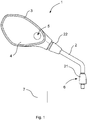
- FIG. 1 a perspective view of a rearview mirror 1 for a single-track motor vehicle with a mirror arm 2 and a housing 3 is shown.
- the rearview mirror 1 can be mounted on a handlebar of a single-track motor vehicle.
- the mirror arm 2 has a first free end 21 which is cylindrical and has a larger diameter than the tubular area.
- At the first free end 21 there is an interface 6 for a control device 7 single-track motor vehicle provided, via which the rearview mirror 1 is electrified.
- the tubular mirror arm 2 first extends the first free end 21, is then angled by approximately 30 ° and then extends in a straight line to a second free end 22 on which the housing 3 of the rearview mirror 1 is arranged.
- the housing 3 is oval and surrounds a mirror 4, which is received in the housing 3.
- a reflective layer of the mirror 4 faces away from the housing 1.
- the rearview mirror 1 comprises a light 5 which is arranged in the housing 3 and behind the reflective layer of the mirror 4.
- the lamp 5 comprises one or more light-emitting diodes for generating different colors and forms in Figure 1 make a circle.
- the alignment of the light 5 is adjusted in such a way that a driver who is standing next to a driver's seat of the parked motorcycle is illuminated. Should the lamp 5 not be aligned in this way, the alignment can be adjusted by means of a play designed for this purpose at the first and second free ends 21, 22.
- the lamp 5 can be automatically controlled by means of the control device 7 via the interface 6.
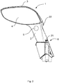
- Figure 2 and 3 show a perspective view of an alternative embodiment of a rearview mirror 1 for a single-track motor vehicle.
- a round housing 3 is arranged at the second free end 22 of the tubular mirror arm 2 and surrounds a likewise round mirror 4, which is accommodated in the housing 3.
- the luminaire 5 is arranged between an outer edge of the mirror 4 and an edge of the housing 3 and extends completely around the mirror 4 along the edge.
- the in Figure 3 The rearview mirror 1 shown has a triangular lamp 5, which is arranged in the mirror arm 2 and is designed according to a warning triangle.
- the luminaire 5 is aligned with respect to the mirror 4 by means of a corresponding play at the first free end 21.
- Another possibility is to change the arrangement of the mirror 4 in the housing 3.
- the mirror 4 is accommodated in the housing 3 in such a way that this has sufficient play in the housing 3 for alignment without impairing the function of the mirror while driving.
Landscapes
- Engineering & Computer Science (AREA)
- Mechanical Engineering (AREA)
- Multimedia (AREA)
- Rear-View Mirror Devices That Are Mounted On The Exterior Of The Vehicle (AREA)
- Lighting Device Outwards From Vehicle And Optical Signal (AREA)
Abstract
Description
- Die Erfindung betrifft einen Rückspiegel für ein einspuriges Kraftfahrzeug mit einem Spiegelarm und einem Gehäuse, sowie ein einspuriges Kraftfahrzeug mit dem Rückspiegel.
- Im Anschluss an eine Fahrt mit einem Motorrad oder einem Roller kann ein Fahrer das Bedürfnis empfinden in einen Spiegel zu sehen, um nach dem Abnehmen des Helms die Frisur oder das Makeup zu überprüfen. Insbesondere nach einer Nachtfahrt wird hierfür jedoch eine externe Lichtquelle zum Ausleuchten des Gesichts des Fahrers benötigt. Überdies weisen bekannte Lösungen mit einer zusätzlichen Lichtquelle eine Reihe von Nachteilen auf. Beispielsweise werden Lösungen offenbart, bei der eine zusätzliche Lichtquelle über einen zusätzlichen Schalter betätigt werden muss. Hierfür ist ein gesonderter Schalter für das Ein- und Ausschalten des Lichts nötig. Weitere Schalter im Bereich des Lenkers erhöhen jedoch die Komplexität des Lenkers bzw. der Schaltelemente in einem ungewünschten Maß und erscheinen an anderen Positionen unzweckmäßig/kompliziert.
- Darüber hinaus sind bei einem einspurigen Kraftfahrzeug die Möglichkeiten stark eingeschränkt, Warnsignale an einen Fahrer oder weitere Verkehrsteilnehmer zu senden.
- Es ist daher Aufgabe der vorliegenden Erfindung, einen Rückspiegel für ein einspuriges Kraftfahrzeug, sowie ein einspuriges Kraftfahrzeug mit dem Rückspiegel bereitzustellen, der bei Nacht/im Dunklen automatisch für ein Spiegelbild des Fahrers genutzt werden kann und Warnsignale an einen Fahrer oder weitere Verkehrsteilnehmer ermöglicht.
- Diese Aufgabe wird durch die Merkmalskombination gemäß Patentanspruch 1 gelöst.
- Erfindungsgemäß wird ein Rückspiegel für ein einspuriges Kraftfahrzeug mit einem Spiegelarm und einem Gehäuse vorgeschlagen. Ein erstes freies Ende des Spiegelarms ist zur Befestigung des Rückspiegels an einem einspurigen Kraftfahrzeug ausgebildet und das Gehäuse ist an einem zweiten freien Ende des Spiegelarms angeordnet. Ferner ist der Rückspiegel elektrifiziert und umfasst eine Leuchte. Das Gehäuse verfügt über einen Spiegel. Außerdem ist an dem Rückspiegel eine Schnittstelle für ein Steuergerät eines einspurigen Kraftfahrzeugs vorgesehen und die Leuchte ist mittels des Steuergeräts steuerbar.
- Auf diese Weise kann eine in einen oder beide Seitenspiegel eingebaute Beleuchtung umgesetzt werden, mit deren Hilfe der Spiegel nachts als beispielsweise Schminkspiegel genutzt werden kann, um z.B. nach dem Abnehmen des Helms die Frisur oder das Makeup zu prüfen. Dabei ist der Fahrer nicht auf eine zusätzliche externe Lichtquelle angewiesen. Aufgrund der Steuerung bzw. Regelung des Lichts mittels des Steuergeräts erfolgt ein automatisches Ein- bzw. Ausschalten des Lichts, ohne dass ein Eingreifen des Fahrers nötig ist. Darüber hinaus kann mittels einer geeigneten Anordnung und Ausrichtung der Leuchte ein Warnsignal an den Fahrer bzw. an weitere Verkehrsteilnehmer gesendet werden.
- In einer vorteilhaften Ausführungsvariante ist vorgesehen, dass die Leuchte zur Erzeugung verschiedener Farben ausgebildet ist. Dabei ist günstig, dass die Farbe der Leuchte an den jeweiligen Anwendungsfall angepasst werden kann. Bei der Verwendung als Schminkspiegel wird beispielsweise ein helles/weißes Licht genutzt und bei einem Warnsignal ein rotes oder orangenes Licht. Hierfür sind Leuchtdioden besonders geeignet, da auf eine bauraumsparende und energiesparende Weise eine Lichtquelle mit ausreichender Intensität bereitgestellt wird.
- Vorzugsweise ist der Rückspiegel derart ausgebildet, dass mittels der Leuchte verschiedene geometrische Formen darstellbar sind, vorzugsweise ein Dreieck, ein Viereck oder ein Kreis. Vorteilhaft daran ist, dass die dargestellte geometrische Form den Effekt der Leuchte verstärkt. Ein kreisförmiges Licht ist zum Beispiel bei der Verwendung des Rückspiegels als Schminkspiegel geeignet, wogegen ein Dreieck für die Darstellung eines Warnsignals besonders günstig ist, da diese Form den Fahrer an ein Warnschild erinnert. Besonders vorteilhaft ist die Darstellung der verschiedenen Geometrien mittels einer Leuchte, die mit einer LED-Anordnung je nach Anwendung unterschiedliche Symbole darstellt.
- In einem Ausführungsbeispiel der Erfindung ist vorgesehen, dass der Spiegelarm zur Montage an einem Lenker eines einspurigen Kraftfahrzeugs ausgebildet ist. Auf diese Weise lässt sich die Variante eines lenkerfesten Rückspiegels umsetzen.
- Ferner ist eine Ausführung günstig, bei der die Leuchte in dem Spiegelarm angeordnet ist. Vorteilhaft daran ist, dass der Spiegelarm eine besonders geeignete Position für die Anordnung der Leuchte ist, da die stromführenden Leitungen des elektrifizierten Rückspiegels durch den Spiegelarm verlaufen und somit der Anschluss der Leuchte an eine stromführende Leitung ohne einer Änderung der Konstruktion bzw. der Verläufe der Leitungen umgesetzt werden kann. Außerdem kann an dem Spiegelarm eine die Leuchte überdeckende und verschiebbare oder klappbare Abdeckung zum Schutz der Leuchte vor Umwelteinflüssen angebracht werden.
- In einer weiteren vorteilhaften Variante ist erfindungsgemäß vorgesehen, dass die Leuchte an einem Außenrand des Spiegels bzw. einem Spiegelglas des Spiegels angeordnet ist und sich entlang der Kante vollständig oder teilweise um den Spiegel erstreckt. Diese Anordnung ist besonders für eine Anwendung als Schminkspiegel geeignet, da ein Gesicht bzw. Kopf des Fahrers optimal ausgeleuchtet werden kann, weil sich die Lichtquelle direkt in einer Blickrichtung des Fahrers zum Spiegel befindet.
- Der erfindungsgemäße Rückspiegel ist in einer Ausführungsvariante ausgebildet, dass die Leuchte in dem Gehäuse und hinter einer reflektierenden Schicht des Spiegels angeordnet ist. Dadurch lassen sich neben einem Ausleuchten des Gesichts bzw. Kopfes eines Fahrers auch Symbole auf dem Spiegel darstellen, die zur Anzeige der Warnsignale dienen.
- Erfindungsgemäß wird ferner ein einspuriges Kraftfahrzeug mit einem Rückspiegel, der entsprechend der vorstehenden Merkmale ausgebildet ist, und einem Steuergerät vorgeschlagen, in dem Daten zur Steuerung der Leuchte hinterlegt sind. Die in dem Steuergerät hinterlegten Daten umfassen Ein- bzw. Ausschaltbedingungen für die Leuchte. Vorteilhaft daran ist, dass der Fahrer die Leuchte nicht betätigen muss, sondern dies automatisch erfolgen kann. Die Ein- bzw. Ausschaltbedingungen für die Leuchte können je nach Anwendungsfall verschiedenste Parameter aufweisen. Grundsätzlich sind die wesentlichen Größen für eine Einschaltbedingung bei einer Anwendung als Schminkspiegel die Geschwindigkeit, der Status der Zündung (an/aus), der Status der Lenkradsperre (an/aus) und die verstrichene Zeit nach einem Abstellen des Motorrads bzw. Ausschalten der Zündung des Motorrads. Eine Ausschaltbedingung ist dabei beispielsweise ein bestimmtes Zeitintervall bzw. eine Änderung der vorstehend genannten Größen. Bei der Nutzung für ein Warnsignal können Einschaltbedingungen beispielsweise Fahrzeuge in einem toten Winkel des Rückspiegels oder die Detektion eines Unfalls sein. Sind die Bedingungen erfüllt, schaltet sich die Leuchte ein. Sobald der entsprechende Parameter die Bedingung nicht mehr erfüllt ist, wird die Leuchte von dem Steuergerät ausgeschaltet. Darüber hinaus ist günstig, dass entweder ein zusätzliches Steuergerät in das einspurige Kraftfahrzeug integriert ist oder auf ein bereits vorhandenes Steuergerät, wie beispielsweise das Motorsteuergerät oder das ABS-Steuergerät, zurückgegriffen wird.
- Weiter vorteilhaft ist es, wenn die in dem Steuergerät hinterlegten Daten eine der jeweiligen Ein- bzw. Ausschaltbedingungen zugeordnete Farbe umfasst. Dadurch leuchtet die Leuchte in einer für den jeweiligen Anwendungsfall optimal geeigneten Farbe. Bei der Verwendung als Schminkspiegel wird beispielsweise ein helles/weißes Licht genutzt und bei einem Warnsignal ein rotes oder orangenes Licht.
- In einer alternativen Ausführung des vorliegenden einspurigen Kraftfahrzeugs ist ferner vorgesehen, dass die in dem Steuergerät hinterlegten Daten eine der jeweiligen Ein- bzw. Ausschaltbedingungen zugeordnete geometrische Form umfasst. Die entsprechend ausgewählte geometrische Form für den jeweiligen Anwendungsfall verstärkt die Wirkung der Leuchte.
- In einer bevorzugten Ausführungsform der Erfindung umfassen die in dem Steuergerät hinterlegten Daten eine einer jeweiligen Ein- bzw. Ausschaltbedingung zugeordnete Dauer des Leuchtens der Leuchte. Vorteilhaft daran ist, dass die Leuchte dem jeweiligen Anwendungsfall entsprechend mit einer bestimmten Dauer leuchtet, sodass auf der einen Seite eine ausreichende Dauer für beispielsweise den Anwendungsfall als Schminkspiegel gewährleistet ist und auf der anderen Seite ein dauerhaftes Leuchten der Leuchte vermieden wird.
- In einem vorteilhaften Ausführungsbeispiel ist vorgesehen, dass die in dem Steuergerät hinterlegten Daten ein einer jeweiligen Ein- bzw. Ausschaltbedingungen zugeordnetes Intervall, das ein aufeinanderfolgendes Ein- bzw. Ausschalten der Leuchte hinsichtlich einer Dauer und einer Anzahl an Wiederholungen regelt. Dabei ist günstig, dass beispielsweise ein Blinken der Leuchte umgesetzt werden kann, falls sich ein weiterer Verkehrsteilnehme in einem toten Winkel des Rückspiegels befindet, um den Fahrer zu warnen. Dabei sind verschiedene Kombinationen von Leuchtdauer und Anzahl an Wiederholungen möglich, wodurch die Wirkung der Leuchte als ein Warnsignal gesteigert wird.
- In einer Ausführungsvariante der Erfindung ist vorgesehen, dass der Rückspiegel zur Montage an einer Verkleidung des einspurigen Kraftfahrzeugs ausgebildet ist und die Leuchte an der Verkleidung anordenbar ist. Dadurch lässt sich eine Variante eines verkleidungsfesten Rückspiegels umsetzen.
- Andere vorteilhafte Weiterbildungen der Erfindung sind in den Unteransprüchen gekennzeichnet bzw. werden nachstehend zusammen mit der Beschreibung der bevorzugten Ausführung der Erfindung anhand der Figuren näher dargestellt. Es zeigen:
- Fig. 1
- eine perspektivische Ansicht eines Rückspiegels für ein Kraftfahrzeug,
- Fig. 2
- eine perspektivische Ansicht einer alternativen Ausführung eines Rückspiegels für ein einspuriges Kraftfahrzeug,
- Fig. 3
- eine perspektivische Ansicht einer weiteren alternativen Ausführung eines Rückspiegels für ein einspuriges Kraftfahrzeug.
- In
Figur 1 ist eine perspektivische Ansicht eines Rückspiegels 1 für ein einspuriges Kraftfahrzeug mit einem Spiegelarm 2 und einem Gehäuse 3 dargestellt. Mittels des rohrförmigen Spiegelarms 2 ist der Rückspiegel 1 an einem Lenker eines einspurigen Kraftfahrzeugs montierbar. Hierfür weist der Spiegelarm 2 ein erstes freies Ende 21 auf, das zylinderförmig ausgebildet ist und einen größeren Durchmesser besitzt als der rohrförmige Bereich. An dem ersten freien Ende 21 ist eine Schnittstelle 6 für ein Steuergerät 7 eines einspurigen Kraftfahrzeugs vorgesehen, über die der Rückspiegel 1 elektrifiziert ist. Der rohrförmige Spiegelarm 2 verlängert zunächst das erste freie Ende 21, ist dann um ungefähr 30 ° abgewinkelt und erstreckt sich anschließend geradlinig bis zu einem zweiten freien Ende 22, an dem das Gehäuse 3 der Rückspiegels 1 angeordnet ist. Das Gehäuse 3 ist oval ausgebildet und umrandet einen Spiegel 4, der in dem Gehäuse 3 aufgenommen ist. Dabei ist eine reflektierende Schicht des Spiegels 4 von dem Gehäuse 1 abgewandt. - Darüber hinaus umfasst der Rückspiegel 1 eine Leuchte 5, die in dem Gehäuse 3 und hinter der reflektierenden Schicht des Spiegels 4 angeordnet ist. Die Leuchte 5 umfasst eine oder mehrere Leuchtdioden zur Erzeugung verschiedener Farben und bildet in
Figur 1 einen Kreis ab. Die Ausrichtung der Leuchte 5 ist derart justiert, dass ein Fahrer, der neben einem Fahrersitz des parkenden Motorrads steht, ausgeleuchtet wird. Sollte die Leuchte 5 nicht auf diese Weise ausgerichtet sein, ist die Ausrichtung mittels einem entsprechend hierfür ausgelegten Spiel an dem ersten und dem zweiten freien Ende 21, 22 einstellbar. Ferner ist die Leuchte 5 mittels des Steuergeräts 7 über die Schnittstelle 6 automatisch steuerbar. -
Figur 2 und3 zeigen eine perspektivische Ansicht einer jeweils alternativen Ausführung eines Rückspiegels 1 für ein einspuriges Kraftfahrzeug. Nachdem die wesentlichen Merkmale der alternativen Ausführungen mit der inFigur 1 beschriebenen Ausführung übereinstimmen, wird im Folgenden lediglich auf die Unterschiede eingegangen. - In der in
Figur 2 dargestellten Ausführung des Rückspiegels 1 ist an dem zweiten freien Ende 22 des rohrförmigen Spiegelarms 2 ein rundes Gehäuse 3 angeordnet, das einen ebenfalls runden Spiegel 4 umrandet, der in dem Gehäuse 3 aufgenommen ist. Die Leuchte 5 ist zwischen einem Außenrand des Spiegels 4 und einer Kante des Gehäuses 3 angeordnet und erstreckt sich entlang der Kante vollständig um den Spiegel 4. - Der in
Figur 3 gezeigte Rückspiegel 1 weist eine dreieckige Leuchte 5 auf, die in dem Spiegelarm 2 angeordnet ist und entsprechend einem Warndreieckt ausgebildet ist. Die Ausrichtung der Leuchte 5 gegenüber dem Spiegel 4 erfolgt mittels eines entsprechenden Spiels an dem ersten freien Ende 21. Eine weitere Möglichkeit ist eine Änderung der Anordnung des Spiegels 4 in dem Gehäuse 3. Hierbei ist der Spiegel 4 derart in dem Gehäuse 3 aufgenommen, dass dieser ein für die Ausrichtung ausreichendes Spiel in dem Gehäuse 3 aufweist, ohne die Funktion des Spiegels während einer Fahrt zu beeinträchtigen.
Claims (13)
- Rückspiegel (1) für ein einspuriges Kraftfahrzeug mit einem Spiegelarm (2) und einem Gehäuse (3), wobei ein erstes freies Ende (21) des Spiegelarms (2) zur Befestigung des Rückspiegels (1) an einem einspurigen Kraftfahrzeug ausgebildet ist und das Gehäuse (3) an einem zweiten freien Ende (22) des Spiegelarms (2) angeordnet ist, wobei in dem Gehäuse (3) ein Spiegel (4) angeordnet ist und wobei der Rückspiegel (1) elektrifiziert ist und eine Leuchte (5) umfasst, dadurch gekennzeichnet, dass an dem Rückspiegel (1) eine Schnittstelle (6) für ein Steuergerät (7) eines einspurigen Kraftfahrzeugs vorgesehen ist, wobei die Leuchte (5) mittels des Steuergeräts (7) steuerbar ist.
- Rückspiegel (1) gemäß Anspruch 1, dadurch gekennzeichnet, dass die Leuchte (5) zur Erzeugung verschiedener Farben ausgebildet ist.
- Rückspiegel (1) gemäß Anspruch 1 oder 2, dadurch gekennzeichnet, dass mittels der Leuchte (5) verschiedene geometrische Formen darstellbar sind, vorzugsweise ein Dreieck, ein Viereck oder ein Kreis.
- Rückspiegel (1) gemäß einem der vorherigen Ansprüche, dadurch gekennzeichnet, dass der Spiegelarm (2) zur Montage an einem Lenker eines einspurigen Kraftfahrzeugs ausgebildet ist.
- Rückspiegel (1) gemäß Anspruch 4, dadurch gekennzeichnet, dass die Leuchte (5) in dem Spiegelarm (2) angeordnet ist.
- Rückspiegel (1) gemäß Anspruch 4, dadurch gekennzeichnet, dass die Leuchte (5) an einem Außenrand des Spiegels (4) angeordnet ist und sich entlang der Kante vollständig oder teilweise um den Spiegel (4) erstreckt.
- Rückspiegel (1) gemäß Anspruch 4, dadurch gekennzeichnet, dass die Leuchte (5) in dem Gehäuse (3) und hinter einer reflektierenden Schicht des Spiegels (4) angeordnet ist.
- Einspuriges Kraftfahrzeug mit einem Rückspiegel (1) gemäß einem der vorherigen Ansprüche und einem Steuergerät (7), in dem Daten (8) zur Steuerung der Leuchte (8) hinterlegt sind, wobei die in dem Steuergerät (7) hinterlegten Daten (8) Ein- bzw. Ausschaltbedingungen für die Leuchte (5) umfassen.
- Einspuriges Kraftfahrzeug gemäß den Ansprüchen 2 und 8, dadurch gekennzeichnet, dass die in dem Steuergerät (7) hinterlegten Daten (8) eine der jeweiligen Ein- bzw. Ausschaltbedingungen zugeordnete Farbe umfasst.
- Einspuriges Kraftfahrzeug gemäß den Ansprüchen 3 und 8 oder 9, dadurch gekennzeichnet, dass die in dem Steuergerät (7) hinterlegten Daten (8) eine der jeweiligen Ein- bzw. Ausschaltbedingungen zugeordnete geometrische Form umfasst.
- Einspuriges Kraftfahrzeug gemäß einem der Ansprüche 8 bis 10, dadurch gekennzeichnet, dass die in dem Steuergerät (7) hinterlegten Daten (8) eine einer jeweiligen Ein- bzw. Ausschaltbedingung zugeordnete Dauer des Leuchtens der Leuchte (5) umfassen.
- Einspuriges Kraftfahrzeug gemäß einem der Ansprüche 8 bis 11, dadurch gekennzeichnet, dass die in dem Steuergerät (7) hinterlegten Daten (8) ein einer jeweiligen Ein- bzw. Ausschaltbedingungen zugeordnetes Intervall umfassen, das ein aufeinanderfolgendes Ein- bzw. Ausschalten der Leuchte (5) hinsichtlich einer Dauer und einer Anzahl an Wiederholungen regelt.
- Einspuriges Kraftfahrzeug gemäß einem der Ansprüche 8 bis 11 und 1 bis 3, dadurch gekennzeichnet, dass der Rückspiegel (1) zur Montage an einer Verkleidung des einspurigen Kraftfahrzeugs ausgebildet ist und die Leuchte (5) an der Verkleidung anordenbar ist.
Applications Claiming Priority (1)
| Application Number | Priority Date | Filing Date | Title |
|---|---|---|---|
| DE102020101252.7A DE102020101252A1 (de) | 2020-01-21 | 2020-01-21 | Rückspiegel für ein einspuriges Kraftfahrzeug |
Publications (2)
| Publication Number | Publication Date |
|---|---|
| EP3854635A1 true EP3854635A1 (de) | 2021-07-28 |
| EP3854635B1 EP3854635B1 (de) | 2023-06-21 |
Family
ID=73654719
Family Applications (1)
| Application Number | Title | Priority Date | Filing Date |
|---|---|---|---|
| EP20210979.9A Active EP3854635B1 (de) | 2020-01-21 | 2020-12-01 | Rückspiegel für ein einspuriges kraftfahrzeug |
Country Status (2)
| Country | Link |
|---|---|
| EP (1) | EP3854635B1 (de) |
| DE (1) | DE102020101252A1 (de) |
Cited By (1)
| Publication number | Priority date | Publication date | Assignee | Title |
|---|---|---|---|---|
| CN117141627A (zh) * | 2022-05-24 | 2023-12-01 | 浙江春风动力股份有限公司 | 后视镜、摩托车及摩托车后视镜光源模组启动方法 |
Citations (9)
| Publication number | Priority date | Publication date | Assignee | Title |
|---|---|---|---|---|
| US20090073704A1 (en) * | 2007-09-19 | 2009-03-19 | Honda Motor Co., Ltd. | Blinker integrated rear-view mirror of saddle-ride type vehicle |
| US20090316285A1 (en) * | 2008-06-06 | 2009-12-24 | Selle Italia S.R.L. | Multifunctional device for vehicles |
| US7717596B1 (en) * | 2005-07-15 | 2010-05-18 | Alan Bell | Rearview mirror assembly with running lights |
| US20100195340A1 (en) * | 2009-01-29 | 2010-08-05 | Kazuyuki Maruyama | Vehicle lighting system |
| US20120099335A1 (en) * | 2010-10-20 | 2012-04-26 | Carl Freudenberg Kg | Light module |
| EP2463156A1 (de) * | 2010-12-10 | 2012-06-13 | SMR Patents S.à.r.l. | Beleuchtungs-Zwischenstück |
| US20120200428A1 (en) * | 2005-07-06 | 2012-08-09 | Donnelly Corporation | Vehicle exterior rearview mirror system with indicator module |
| DE102011015148A1 (de) * | 2011-03-25 | 2012-09-27 | Osram Opto Semiconductors Gmbh | Anordnung eines lichtemittierenden Halbleiterbauelementes und einer Lichtleiterschicht |
| WO2017084790A1 (de) * | 2015-11-17 | 2017-05-26 | Robert Bosch Gmbh | Rückspiegel für ein zweirad |
-
2020
- 2020-01-21 DE DE102020101252.7A patent/DE102020101252A1/de active Pending
- 2020-12-01 EP EP20210979.9A patent/EP3854635B1/de active Active
Patent Citations (9)
| Publication number | Priority date | Publication date | Assignee | Title |
|---|---|---|---|---|
| US20120200428A1 (en) * | 2005-07-06 | 2012-08-09 | Donnelly Corporation | Vehicle exterior rearview mirror system with indicator module |
| US7717596B1 (en) * | 2005-07-15 | 2010-05-18 | Alan Bell | Rearview mirror assembly with running lights |
| US20090073704A1 (en) * | 2007-09-19 | 2009-03-19 | Honda Motor Co., Ltd. | Blinker integrated rear-view mirror of saddle-ride type vehicle |
| US20090316285A1 (en) * | 2008-06-06 | 2009-12-24 | Selle Italia S.R.L. | Multifunctional device for vehicles |
| US20100195340A1 (en) * | 2009-01-29 | 2010-08-05 | Kazuyuki Maruyama | Vehicle lighting system |
| US20120099335A1 (en) * | 2010-10-20 | 2012-04-26 | Carl Freudenberg Kg | Light module |
| EP2463156A1 (de) * | 2010-12-10 | 2012-06-13 | SMR Patents S.à.r.l. | Beleuchtungs-Zwischenstück |
| DE102011015148A1 (de) * | 2011-03-25 | 2012-09-27 | Osram Opto Semiconductors Gmbh | Anordnung eines lichtemittierenden Halbleiterbauelementes und einer Lichtleiterschicht |
| WO2017084790A1 (de) * | 2015-11-17 | 2017-05-26 | Robert Bosch Gmbh | Rückspiegel für ein zweirad |
Cited By (1)
| Publication number | Priority date | Publication date | Assignee | Title |
|---|---|---|---|---|
| CN117141627A (zh) * | 2022-05-24 | 2023-12-01 | 浙江春风动力股份有限公司 | 后视镜、摩托车及摩托车后视镜光源模组启动方法 |
Also Published As
| Publication number | Publication date |
|---|---|
| DE102020101252A1 (de) | 2021-07-22 |
| EP3854635B1 (de) | 2023-06-21 |
Similar Documents
| Publication | Publication Date | Title |
|---|---|---|
| DE102007027529B3 (de) | Warneinrichtung für ein Kraftfahrzeug | |
| DE19538770A1 (de) | Außenrückblickspiegel für Fahrzeuge, vorzugsweise für Kraftfahrzeuge | |
| DE102019202020A1 (de) | Lenksteuervorrichtung mit einem Anzeigeleuchtensystem für ein Kraftfahrzeug und Verfahren zum Betreiben eines Anzeigeleuchtensystems einer Lenksteuervorrichtung | |
| EP1508476A2 (de) | Fahrerassistenzsystem für Kraftfahrzeuge | |
| DE202017105444U1 (de) | Kraftfahrzeugsteuereinheit sowie Kraftfahrzeuginformationssystem | |
| EP3854635B1 (de) | Rückspiegel für ein einspuriges kraftfahrzeug | |
| WO2012163670A1 (de) | Fahrzeugcomputer zur projektions eines betriebsparameters auf die fahrbahn | |
| DE102006008278A1 (de) | Vorrichtung zum Erkennenlassen eines Fahrzeugs | |
| DE102007045645A1 (de) | Verfahren zur Steuerung einer Nachtsichteinrichtung und eines Scheinwerfers eines Fahrzeugs | |
| DE19908734C1 (de) | Vorrichtung für Fahrzeugtüren | |
| DE19836526A1 (de) | Zusätzliche Bremsleuchte (vorne) | |
| DE102009005777A1 (de) | Beleuchtung für Fahrzeuge | |
| CH695857A5 (de) | Türöffnungswarnvorrichtung eines Motorfahrzeuges. | |
| DE102017119776A1 (de) | Verfahren zur Ansteuerung mindestens eines Hauptscheinwerfers, Beleuchtungseinheit, Computerprogrammprodukt und computerlesbares Medium | |
| DE102019119591A1 (de) | Betreiben eines Lichtprojektors eines Fahrzeugs | |
| DE202016104410U1 (de) | Signalvorrichtung zur Verwendung im Straßenverkehr | |
| DE102009009379B3 (de) | Spiegelanordnung für Fahrzeuge sowie Fahrzeug mit einer solchen Spiegelanordnung | |
| DE19741452C2 (de) | Blinkanlage für Fahrräder | |
| DE102006008279A1 (de) | Fahrzeugerkennungsvorrichtung | |
| DE10355023A1 (de) | Vorrichtung zum Abdecken einer Fahrzeugoberfläche | |
| CH681796A5 (en) | Front signalling lamps for road vehicle - uses front mounted braking lamps operated by brake contact to provide signal for pedestrian. | |
| DE816060C (de) | Rueckblickspiegel fuer Aussenbefestigung | |
| DE820388C (de) | Fahrtrichtungsanzeiger fuer Kraftraeder | |
| DE19648143A1 (de) | Bremssignalisierung an der Frontscheibe | |
| DE4021509A1 (de) | Motorfahrzeug mit lichttechnischer einrichtung, insbesondere blinkern |
Legal Events
| Date | Code | Title | Description |
|---|---|---|---|
| PUAI | Public reference made under article 153(3) epc to a published international application that has entered the european phase |
Free format text: ORIGINAL CODE: 0009012 |
|
| STAA | Information on the status of an ep patent application or granted ep patent |
Free format text: STATUS: THE APPLICATION HAS BEEN PUBLISHED |
|
| AK | Designated contracting states |
Kind code of ref document: A1 Designated state(s): AL AT BE BG CH CY CZ DE DK EE ES FI FR GB GR HR HU IE IS IT LI LT LU LV MC MK MT NL NO PL PT RO RS SE SI SK SM TR |
|
| STAA | Information on the status of an ep patent application or granted ep patent |
Free format text: STATUS: REQUEST FOR EXAMINATION WAS MADE |
|
| 17P | Request for examination filed |
Effective date: 20211122 |
|
| RBV | Designated contracting states (corrected) |
Designated state(s): AL AT BE BG CH CY CZ DE DK EE ES FI FR GB GR HR HU IE IS IT LI LT LU LV MC MK MT NL NO PL PT RO RS SE SI SK SM TR |
|
| GRAP | Despatch of communication of intention to grant a patent |
Free format text: ORIGINAL CODE: EPIDOSNIGR1 |
|
| STAA | Information on the status of an ep patent application or granted ep patent |
Free format text: STATUS: GRANT OF PATENT IS INTENDED |
|
| INTG | Intention to grant announced |
Effective date: 20230314 |
|
| GRAS | Grant fee paid |
Free format text: ORIGINAL CODE: EPIDOSNIGR3 |
|
| GRAA | (expected) grant |
Free format text: ORIGINAL CODE: 0009210 |
|
| STAA | Information on the status of an ep patent application or granted ep patent |
Free format text: STATUS: THE PATENT HAS BEEN GRANTED |
|
| P01 | Opt-out of the competence of the unified patent court (upc) registered |
Effective date: 20230502 |
|
| AK | Designated contracting states |
Kind code of ref document: B1 Designated state(s): AL AT BE BG CH CY CZ DE DK EE ES FI FR GB GR HR HU IE IS IT LI LT LU LV MC MK MT NL NO PL PT RO RS SE SI SK SM TR |
|
| REG | Reference to a national code |
Ref country code: CH Ref legal event code: EP |
|
| REG | Reference to a national code |
Ref country code: DE Ref legal event code: R096 Ref document number: 502020003853 Country of ref document: DE |
|
| REG | Reference to a national code |
Ref country code: AT Ref legal event code: REF Ref document number: 1580709 Country of ref document: AT Kind code of ref document: T Effective date: 20230715 |
|
| REG | Reference to a national code |
Ref country code: IE Ref legal event code: FG4D Free format text: LANGUAGE OF EP DOCUMENT: GERMAN |
|
| P02 | Opt-out of the competence of the unified patent court (upc) changed |
Effective date: 20230808 |
|
| REG | Reference to a national code |
Ref country code: LT Ref legal event code: MG9D |
|
| REG | Reference to a national code |
Ref country code: NL Ref legal event code: MP Effective date: 20230621 |
|
| PG25 | Lapsed in a contracting state [announced via postgrant information from national office to epo] |
Ref country code: SE Free format text: LAPSE BECAUSE OF FAILURE TO SUBMIT A TRANSLATION OF THE DESCRIPTION OR TO PAY THE FEE WITHIN THE PRESCRIBED TIME-LIMIT Effective date: 20230621 Ref country code: NO Free format text: LAPSE BECAUSE OF FAILURE TO SUBMIT A TRANSLATION OF THE DESCRIPTION OR TO PAY THE FEE WITHIN THE PRESCRIBED TIME-LIMIT Effective date: 20230921 |
|
| PG25 | Lapsed in a contracting state [announced via postgrant information from national office to epo] |
Ref country code: RS Free format text: LAPSE BECAUSE OF FAILURE TO SUBMIT A TRANSLATION OF THE DESCRIPTION OR TO PAY THE FEE WITHIN THE PRESCRIBED TIME-LIMIT Effective date: 20230621 Ref country code: NL Free format text: LAPSE BECAUSE OF FAILURE TO SUBMIT A TRANSLATION OF THE DESCRIPTION OR TO PAY THE FEE WITHIN THE PRESCRIBED TIME-LIMIT Effective date: 20230621 Ref country code: LV Free format text: LAPSE BECAUSE OF FAILURE TO SUBMIT A TRANSLATION OF THE DESCRIPTION OR TO PAY THE FEE WITHIN THE PRESCRIBED TIME-LIMIT Effective date: 20230621 Ref country code: LT Free format text: LAPSE BECAUSE OF FAILURE TO SUBMIT A TRANSLATION OF THE DESCRIPTION OR TO PAY THE FEE WITHIN THE PRESCRIBED TIME-LIMIT Effective date: 20230621 Ref country code: HR Free format text: LAPSE BECAUSE OF FAILURE TO SUBMIT A TRANSLATION OF THE DESCRIPTION OR TO PAY THE FEE WITHIN THE PRESCRIBED TIME-LIMIT Effective date: 20230621 Ref country code: GR Free format text: LAPSE BECAUSE OF FAILURE TO SUBMIT A TRANSLATION OF THE DESCRIPTION OR TO PAY THE FEE WITHIN THE PRESCRIBED TIME-LIMIT Effective date: 20230922 |
|
| PG25 | Lapsed in a contracting state [announced via postgrant information from national office to epo] |
Ref country code: FI Free format text: LAPSE BECAUSE OF FAILURE TO SUBMIT A TRANSLATION OF THE DESCRIPTION OR TO PAY THE FEE WITHIN THE PRESCRIBED TIME-LIMIT Effective date: 20230621 |
|
| PG25 | Lapsed in a contracting state [announced via postgrant information from national office to epo] |
Ref country code: SK Free format text: LAPSE BECAUSE OF FAILURE TO SUBMIT A TRANSLATION OF THE DESCRIPTION OR TO PAY THE FEE WITHIN THE PRESCRIBED TIME-LIMIT Effective date: 20230621 |
|
| PG25 | Lapsed in a contracting state [announced via postgrant information from national office to epo] |
Ref country code: ES Free format text: LAPSE BECAUSE OF FAILURE TO SUBMIT A TRANSLATION OF THE DESCRIPTION OR TO PAY THE FEE WITHIN THE PRESCRIBED TIME-LIMIT Effective date: 20230621 |
|
| PG25 | Lapsed in a contracting state [announced via postgrant information from national office to epo] |
Ref country code: IS Free format text: LAPSE BECAUSE OF FAILURE TO SUBMIT A TRANSLATION OF THE DESCRIPTION OR TO PAY THE FEE WITHIN THE PRESCRIBED TIME-LIMIT Effective date: 20231021 |
|
| PG25 | Lapsed in a contracting state [announced via postgrant information from national office to epo] |
Ref country code: SM Free format text: LAPSE BECAUSE OF FAILURE TO SUBMIT A TRANSLATION OF THE DESCRIPTION OR TO PAY THE FEE WITHIN THE PRESCRIBED TIME-LIMIT Effective date: 20230621 Ref country code: SK Free format text: LAPSE BECAUSE OF FAILURE TO SUBMIT A TRANSLATION OF THE DESCRIPTION OR TO PAY THE FEE WITHIN THE PRESCRIBED TIME-LIMIT Effective date: 20230621 Ref country code: RO Free format text: LAPSE BECAUSE OF FAILURE TO SUBMIT A TRANSLATION OF THE DESCRIPTION OR TO PAY THE FEE WITHIN THE PRESCRIBED TIME-LIMIT Effective date: 20230621 Ref country code: PT Free format text: LAPSE BECAUSE OF FAILURE TO SUBMIT A TRANSLATION OF THE DESCRIPTION OR TO PAY THE FEE WITHIN THE PRESCRIBED TIME-LIMIT Effective date: 20231023 Ref country code: IS Free format text: LAPSE BECAUSE OF FAILURE TO SUBMIT A TRANSLATION OF THE DESCRIPTION OR TO PAY THE FEE WITHIN THE PRESCRIBED TIME-LIMIT Effective date: 20231021 Ref country code: ES Free format text: LAPSE BECAUSE OF FAILURE TO SUBMIT A TRANSLATION OF THE DESCRIPTION OR TO PAY THE FEE WITHIN THE PRESCRIBED TIME-LIMIT Effective date: 20230621 Ref country code: EE Free format text: LAPSE BECAUSE OF FAILURE TO SUBMIT A TRANSLATION OF THE DESCRIPTION OR TO PAY THE FEE WITHIN THE PRESCRIBED TIME-LIMIT Effective date: 20230621 Ref country code: CZ Free format text: LAPSE BECAUSE OF FAILURE TO SUBMIT A TRANSLATION OF THE DESCRIPTION OR TO PAY THE FEE WITHIN THE PRESCRIBED TIME-LIMIT Effective date: 20230621 |
|
| PG25 | Lapsed in a contracting state [announced via postgrant information from national office to epo] |
Ref country code: PL Free format text: LAPSE BECAUSE OF FAILURE TO SUBMIT A TRANSLATION OF THE DESCRIPTION OR TO PAY THE FEE WITHIN THE PRESCRIBED TIME-LIMIT Effective date: 20230621 |
|
| REG | Reference to a national code |
Ref country code: DE Ref legal event code: R097 Ref document number: 502020003853 Country of ref document: DE |
|
| PLBE | No opposition filed within time limit |
Free format text: ORIGINAL CODE: 0009261 |
|
| STAA | Information on the status of an ep patent application or granted ep patent |
Free format text: STATUS: NO OPPOSITION FILED WITHIN TIME LIMIT |
|
| PG25 | Lapsed in a contracting state [announced via postgrant information from national office to epo] |
Ref country code: DK Free format text: LAPSE BECAUSE OF FAILURE TO SUBMIT A TRANSLATION OF THE DESCRIPTION OR TO PAY THE FEE WITHIN THE PRESCRIBED TIME-LIMIT Effective date: 20230621 |
|
| PG25 | Lapsed in a contracting state [announced via postgrant information from national office to epo] |
Ref country code: SI Free format text: LAPSE BECAUSE OF FAILURE TO SUBMIT A TRANSLATION OF THE DESCRIPTION OR TO PAY THE FEE WITHIN THE PRESCRIBED TIME-LIMIT Effective date: 20230621 |
|
| 26N | No opposition filed |
Effective date: 20240322 |
|
| PG25 | Lapsed in a contracting state [announced via postgrant information from national office to epo] |
Ref country code: SI Free format text: LAPSE BECAUSE OF FAILURE TO SUBMIT A TRANSLATION OF THE DESCRIPTION OR TO PAY THE FEE WITHIN THE PRESCRIBED TIME-LIMIT Effective date: 20230621 |
|
| REG | Reference to a national code |
Ref country code: CH Ref legal event code: PL |
|
| PG25 | Lapsed in a contracting state [announced via postgrant information from national office to epo] |
Ref country code: LU Free format text: LAPSE BECAUSE OF NON-PAYMENT OF DUE FEES Effective date: 20231201 |
|
| PG25 | Lapsed in a contracting state [announced via postgrant information from national office to epo] |
Ref country code: MC Free format text: LAPSE BECAUSE OF FAILURE TO SUBMIT A TRANSLATION OF THE DESCRIPTION OR TO PAY THE FEE WITHIN THE PRESCRIBED TIME-LIMIT Effective date: 20230621 |
|
| REG | Reference to a national code |
Ref country code: BE Ref legal event code: MM Effective date: 20231231 |
|
| PG25 | Lapsed in a contracting state [announced via postgrant information from national office to epo] |
Ref country code: MC Free format text: LAPSE BECAUSE OF FAILURE TO SUBMIT A TRANSLATION OF THE DESCRIPTION OR TO PAY THE FEE WITHIN THE PRESCRIBED TIME-LIMIT Effective date: 20230621 Ref country code: LU Free format text: LAPSE BECAUSE OF NON-PAYMENT OF DUE FEES Effective date: 20231201 |
|
| REG | Reference to a national code |
Ref country code: IE Ref legal event code: MM4A |
|
| PG25 | Lapsed in a contracting state [announced via postgrant information from national office to epo] |
Ref country code: IE Free format text: LAPSE BECAUSE OF NON-PAYMENT OF DUE FEES Effective date: 20231201 |
|
| PG25 | Lapsed in a contracting state [announced via postgrant information from national office to epo] |
Ref country code: BE Free format text: LAPSE BECAUSE OF NON-PAYMENT OF DUE FEES Effective date: 20231231 |
|
| PG25 | Lapsed in a contracting state [announced via postgrant information from national office to epo] |
Ref country code: CH Free format text: LAPSE BECAUSE OF NON-PAYMENT OF DUE FEES Effective date: 20231231 |
|
| PG25 | Lapsed in a contracting state [announced via postgrant information from national office to epo] |
Ref country code: IE Free format text: LAPSE BECAUSE OF NON-PAYMENT OF DUE FEES Effective date: 20231201 Ref country code: CH Free format text: LAPSE BECAUSE OF NON-PAYMENT OF DUE FEES Effective date: 20231231 Ref country code: BE Free format text: LAPSE BECAUSE OF NON-PAYMENT OF DUE FEES Effective date: 20231231 |
|
| PG25 | Lapsed in a contracting state [announced via postgrant information from national office to epo] |
Ref country code: BG Free format text: LAPSE BECAUSE OF FAILURE TO SUBMIT A TRANSLATION OF THE DESCRIPTION OR TO PAY THE FEE WITHIN THE PRESCRIBED TIME-LIMIT Effective date: 20230621 |
|
| PG25 | Lapsed in a contracting state [announced via postgrant information from national office to epo] |
Ref country code: BG Free format text: LAPSE BECAUSE OF FAILURE TO SUBMIT A TRANSLATION OF THE DESCRIPTION OR TO PAY THE FEE WITHIN THE PRESCRIBED TIME-LIMIT Effective date: 20230621 |
|
| PG25 | Lapsed in a contracting state [announced via postgrant information from national office to epo] |
Ref country code: CY Free format text: LAPSE BECAUSE OF FAILURE TO SUBMIT A TRANSLATION OF THE DESCRIPTION OR TO PAY THE FEE WITHIN THE PRESCRIBED TIME-LIMIT; INVALID AB INITIO Effective date: 20201201 |
|
| PG25 | Lapsed in a contracting state [announced via postgrant information from national office to epo] |
Ref country code: HU Free format text: LAPSE BECAUSE OF FAILURE TO SUBMIT A TRANSLATION OF THE DESCRIPTION OR TO PAY THE FEE WITHIN THE PRESCRIBED TIME-LIMIT; INVALID AB INITIO Effective date: 20201201 |
|
| PG25 | Lapsed in a contracting state [announced via postgrant information from national office to epo] |
Ref country code: TR Free format text: LAPSE BECAUSE OF FAILURE TO SUBMIT A TRANSLATION OF THE DESCRIPTION OR TO PAY THE FEE WITHIN THE PRESCRIBED TIME-LIMIT Effective date: 20230621 |
|
| PGFP | Annual fee paid to national office [announced via postgrant information from national office to epo] |
Ref country code: DE Payment date: 20251203 Year of fee payment: 6 |
|
| PGFP | Annual fee paid to national office [announced via postgrant information from national office to epo] |
Ref country code: GB Payment date: 20251218 Year of fee payment: 6 |
|
| PGFP | Annual fee paid to national office [announced via postgrant information from national office to epo] |
Ref country code: AT Payment date: 20260113 Year of fee payment: 5 |
|
| PGFP | Annual fee paid to national office [announced via postgrant information from national office to epo] |
Ref country code: FR Payment date: 20251217 Year of fee payment: 6 |
|
| PGFP | Annual fee paid to national office [announced via postgrant information from national office to epo] |
Ref country code: IT Payment date: 20251231 Year of fee payment: 6 |