EP3852299B1 - Referenzsignalkonfigurationsverfahren und -vorrichtung - Google Patents
Referenzsignalkonfigurationsverfahren und -vorrichtung Download PDFInfo
- Publication number
- EP3852299B1 EP3852299B1 EP20212106.7A EP20212106A EP3852299B1 EP 3852299 B1 EP3852299 B1 EP 3852299B1 EP 20212106 A EP20212106 A EP 20212106A EP 3852299 B1 EP3852299 B1 EP 3852299B1
- Authority
- EP
- European Patent Office
- Prior art keywords
- ptrs
- mcs
- domain density
- time domain
- correspondence
- Prior art date
- Legal status (The legal status is an assumption and is not a legal conclusion. Google has not performed a legal analysis and makes no representation as to the accuracy of the status listed.)
- Active
Links
Images


Classifications
-
- H—ELECTRICITY
- H04—ELECTRIC COMMUNICATION TECHNIQUE
- H04W—WIRELESS COMMUNICATION NETWORKS
- H04W72/00—Local resource management
- H04W72/20—Control channels or signalling for resource management
- H04W72/21—Control channels or signalling for resource management in the uplink direction of a wireless link, i.e. towards the network
-
- H—ELECTRICITY
- H04—ELECTRIC COMMUNICATION TECHNIQUE
- H04L—TRANSMISSION OF DIGITAL INFORMATION, e.g. TELEGRAPHIC COMMUNICATION
- H04L1/00—Arrangements for detecting or preventing errors in the information received
- H04L1/0001—Systems modifying transmission characteristics according to link quality, e.g. power backoff
- H04L1/0002—Systems modifying transmission characteristics according to link quality, e.g. power backoff by adapting the transmission rate
- H04L1/0003—Systems modifying transmission characteristics according to link quality, e.g. power backoff by adapting the transmission rate by switching between different modulation schemes
-
- H—ELECTRICITY
- H04—ELECTRIC COMMUNICATION TECHNIQUE
- H04L—TRANSMISSION OF DIGITAL INFORMATION, e.g. TELEGRAPHIC COMMUNICATION
- H04L27/00—Modulated-carrier systems
- H04L27/26—Systems using multi-frequency codes
- H04L27/2601—Multicarrier modulation systems
- H04L27/2602—Signal structure
- H04L27/261—Details of reference signals
- H04L27/2613—Structure of the reference signals
- H04L27/26134—Pilot insertion in the transmitter chain, e.g. pilot overlapping with data, insertion in time or frequency domain
-
- H—ELECTRICITY
- H04—ELECTRIC COMMUNICATION TECHNIQUE
- H04L—TRANSMISSION OF DIGITAL INFORMATION, e.g. TELEGRAPHIC COMMUNICATION
- H04L5/00—Arrangements affording multiple use of the transmission path
- H04L5/0001—Arrangements for dividing the transmission path
- H04L5/0003—Two-dimensional division
- H04L5/0005—Time-frequency
-
- H—ELECTRICITY
- H04—ELECTRIC COMMUNICATION TECHNIQUE
- H04L—TRANSMISSION OF DIGITAL INFORMATION, e.g. TELEGRAPHIC COMMUNICATION
- H04L5/00—Arrangements affording multiple use of the transmission path
- H04L5/003—Arrangements for allocating sub-channels of the transmission path
- H04L5/0048—Allocation of pilot signals, i.e. of signals known to the receiver
-
- H—ELECTRICITY
- H04—ELECTRIC COMMUNICATION TECHNIQUE
- H04L—TRANSMISSION OF DIGITAL INFORMATION, e.g. TELEGRAPHIC COMMUNICATION
- H04L5/00—Arrangements affording multiple use of the transmission path
- H04L5/0091—Signalling for the administration of the divided path, e.g. signalling of configuration information
- H04L5/0094—Indication of how sub-channels of the path are allocated
-
- H—ELECTRICITY
- H04—ELECTRIC COMMUNICATION TECHNIQUE
- H04L—TRANSMISSION OF DIGITAL INFORMATION, e.g. TELEGRAPHIC COMMUNICATION
- H04L5/00—Arrangements affording multiple use of the transmission path
- H04L5/0091—Signalling for the administration of the divided path, e.g. signalling of configuration information
- H04L5/0096—Indication of changes in allocation
- H04L5/0098—Signalling of the activation or deactivation of component carriers, subcarriers or frequency bands
-
- H—ELECTRICITY
- H04—ELECTRIC COMMUNICATION TECHNIQUE
- H04W—WIRELESS COMMUNICATION NETWORKS
- H04W72/00—Local resource management
- H04W72/04—Wireless resource allocation
-
- H—ELECTRICITY
- H04—ELECTRIC COMMUNICATION TECHNIQUE
- H04W—WIRELESS COMMUNICATION NETWORKS
- H04W72/00—Local resource management
- H04W72/20—Control channels or signalling for resource management
- H04W72/23—Control channels or signalling for resource management in the downlink direction of a wireless link, i.e. towards a terminal
-
- H—ELECTRICITY
- H04—ELECTRIC COMMUNICATION TECHNIQUE
- H04L—TRANSMISSION OF DIGITAL INFORMATION, e.g. TELEGRAPHIC COMMUNICATION
- H04L5/00—Arrangements affording multiple use of the transmission path
- H04L5/0001—Arrangements for dividing the transmission path
- H04L5/0003—Two-dimensional division
- H04L5/0005—Time-frequency
- H04L5/0007—Time-frequency the frequencies being orthogonal, e.g. OFDM(A) or DMT
-
- H—ELECTRICITY
- H04—ELECTRIC COMMUNICATION TECHNIQUE
- H04L—TRANSMISSION OF DIGITAL INFORMATION, e.g. TELEGRAPHIC COMMUNICATION
- H04L5/00—Arrangements affording multiple use of the transmission path
- H04L5/0091—Signalling for the administration of the divided path, e.g. signalling of configuration information
Definitions
- the present invention relates to the field of communications technologies, and in particular, to a reference signal configuration method, an apparatus, and a system.
- MIMO-OFDM Massive input massive output-Orthogonal Frequency Division Multiplexing
- FFT Fast Fourier Transform
- phase noise on OFDM performance mainly lies in two aspects: a common phase error (Common Phase Error, CPE) and inter-carrier interference (Inter-carrier Interference, ICI), and impact of the CFO on the OFDM performance mainly lies in the ICI.
- CPE Common Phase Error
- ICI Inter-carrier Interference
- impact of the CFO on the OFDM performance mainly lies in the ICI.
- the ICI has weaker impact on performance than the CPE. Therefore, usually the CPE is preferably compensated for in a phase noise compensation solution.
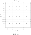
- Phase noise is used as an example. As a frequency band increases, a phase noise level decreases by 20*log(f1/f2). A 2 GHz frequency band and a 28 GHz frequency band are used as examples. A phase noise level of the 28 GHz frequency band is 23 dB higher than that of the 2 GHz frequency band. A higher phase noise level indicates stronger common phase error (Common Phase Error, CPE) impact and a larger phase error caused by a CPE, as shown in FIG. 1A to FIG. 1C .
- CPE Common Phase Error
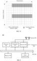
- phase noise reference signals Different subcarriers in a same OFDM symbol are under same impact of a CPE. Phase errors on different subcarriers are different because of impact of white Gaussian noise. Therefore, in frequency domain, a plurality of estimated phase noise values are obtained by using a specific quantity of phase noise reference signals, and the plurality of estimated phase noise values are averaged to obtain a CPE, to reduce the impact of the white Gaussian noise to a greatest extent. Theoretically, a larger quantity of phase noise reference signals indicates a better averaging effect and a more accurately estimated CPE. In time domain, because phase noise varies discontinuously, and there is no linear relationship between different symbols, performance is poorer if time domain pilots are sparser. In addition, a larger quantity of phase noise reference signals indicates more occupied time-frequency resources and higher overheads. Therefore, a compromise needs to be made between performance and overheads to determine the quantity of phase noise reference signals.
- phase tracking reference signal (the reference signal may also be referred to as a pilot) design solution, as shown in FIG. 2A-1 and FIG. 2A-2 and FIG. 2B-1 and FIG. 2B-2 .
- a demodulation reference signal (Demodulation Reference Signal, DMRS) and a phase compensation reference signal (Phase compensation Reference Signal, PCRS) (which may also be referred to as a phase tracking reference signal (Phase tracking Reference Signal, PTRS), and the PCRS and the PTRS are not uniformly named in the industry currently and are collectively referred to as the PTRS subsequently for ease of description in the present invention) are used to complete channel estimation, phase noise estimation, and data demodulation together for both uplink and downlink.
- DMRS Demodulation Reference Signal
- PCRS Phase compensation Reference Signal
- PTRS Phase tracking Reference Signal
- LG ELECTRONICS "Reference Signal for Frequency offset and Phase Tracking", vol. RAN WG1, no. Reno, USA; 20161114 - 20161118, (20161113), 3GPP DRAFT; R1-1611809, 3RD GENERATION PARTNERSHIP PROJECT (3GPP), MOBILE COMPETENCE CENTRE; 650, ROUTE DES LUCIOLES; F-06921 SOPHIA-ANTIPOLIS CEDEX; FRANCE, URL: http://www.3gpp.org/ftp/Meetings_3GPP_SYNC/RANl/Docs/, (20161113 ), mainly also generally discloses different time domain density (see patterns #1, #2 and #3 in Figure 1 ), patterns #2 can be taken into account for high MCS.
- PTRSs are consecutive in time domain, and a frequency division manner is used for a plurality of ports in frequency domain.
- a time domain density and a frequency domain density are fixed values, and a relatively large quantity of subcarriers are occupied and overheads are relatively high when a data bandwidth is large.
- the prior art is not flexible enough because the fixed time domain density and the fixed frequency domain density are used for different scenarios such as different phase noise levels and different moving speeds.
- Embodiments of the present invention provide a reference signal configuration method. This can reduce resource overheads, is more flexible, and better fits requirements of different future 5G scenarios in comparison with the prior art.
- a correspondence between the PTRS and the modulation and coding scheme and the bandwidth is used to implicitly indicate the time-frequency location of the PTRS.
- no explicit indication is required, and signaling overheads are reduced.
- the terminal 32 in the present invention may communicate with one or more core networks by using a radio access network (Radio Access Network, RAN).
- the terminal 32 may be an access terminal, a subscriber unit, a subscriber station, a mobile station, a mobile console, a remote station, a remote terminal, a mobile device, a user terminal, a terminal, a wireless communications device, a user agent, or a user apparatus.
- the access terminal may be a cellular phone, a cordless phone, a Session Initiation Protocol (Session Initiation Protocol, SIP for short) phone, a wireless local loop (Wireless Local Loop, WLL for short) station, a personal digital assistant (Personal Digital Assistant, PDA for short), a handheld device having a wireless communication function, a computing device, another processing device connected to a wireless modem, an in-vehicle device, a wearable device, a terminal in a 5G network, or the like.
- Session Initiation Protocol Session Initiation Protocol, SIP for short
- WLL Wireless Local Loop
- PDA Personal Digital Assistant
- the base station 31 in the present invention may be a Wireless Fidelity (Wireless Fidelity, Wi-Fi) station, an eNodeB in LTE, or a base station in next generation communication, for example, a 5G base station gNB, a small cell, a micro base station, or may be a relay node, an access point, an in-vehicle device, a wearable device, or the like operating on a high frequency band.
- a Wireless Fidelity Wireless Fidelity, Wi-Fi
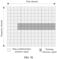
- a PTRS is mapped to one or more OFDM symbols at a specific time domain density and a specific frequency domain density.
- the PTRS is usually used to track a rapid channel change, for example, track changes of a carrier frequency offset (Carrier Frequency Offset, CFO), phase noise (Phase noise, PN), and a Doppler shift.
- CFO Carrier Frequency Offset
- PN phase noise
- an embodiment of the present invention provides a reference signal configuration method.
- the method includes the following steps.
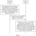
- a transmit device maps a PTRS to one or more OFDM symbols based on information about a correspondence between the PTRS and one or more of a modulation and coding scheme (MCS), a bandwidth (BW), and a subcarrier spacing (SC).
- MCS modulation and coding scheme
- BW bandwidth
- SC subcarrier spacing
- the transmit device sends the one or more OFDM symbols to which the PTRS is mapped to a receive device.
- the receive device receives the one or more OFDM symbols from the transmit device, and determines the PTRS from the one or more OFDM symbols based on the information about the correspondence between the PTRS and the one or more of the modulation and coding scheme (MCS), the bandwidth (BW), and the subcarrier spacing (SC).
- MCS modulation and coding scheme
- BW bandwidth
- SC subcarrier spacing
- the method further includes: S501: Determine whether to map the phase tracking reference signal (PTRS).
- PTRS phase tracking reference signal
- Step S501 of determining whether to map the phase tracking reference signal (PTRS) specifically includes the following implementations.
- MCS modulation and coding scheme
- PTRS phase tracking reference signal
- MCS index a value of the modulation and coding scheme
- the MCS is used to indicate a modulation order and a bit rate
- one MCS index corresponds to one modulation order and one bit rate.
- a 3GPP R14 protocol is used as an example.
- One MCS index corresponds to one modulation order and one transport block size (Transport Block Size, TBS), and a TBS index is a parameter corresponding to the bit rate, as shown in Table 2.
- TBS Transport Block Size
- M0 indicates a first threshold for determining whether to map the PTRS
- M1 indicates a second threshold for determining whether to map the PTRS
- B0 indicates a BW threshold for determining whether to map the PTRS.
- the thresholds M0, B0, and M1 mentioned above may be constants as specified in a standard, or may be dynamically adjusted. If the thresholds need to be dynamically adjusted, a base station side may actively initiate a threshold adjustment, or a terminal side may actively initiate an adjustment request.
- the base station may use higher layer signaling to instruct to adjust the MCS threshold M0, or instruct to adjust the MCS threshold M1 and the BW threshold B0, to adapt to different scenarios and conditions.
- the MCS threshold M0, or the MCS threshold M1 and the BW threshold B0 are adjusted by using signaling in the following two manners:
- a PTRS-related operation is terminated; or when the preset condition mentioned in the foregoing embodiment is met, a PTRS time domain density and a PTRS frequency domain density need to be determined based on information provided in the following embodiment.
- step S502 of mapping a PTRS to one or more OFDM symbols based on information about a correspondence between the PTRS and one or more of a modulation and coding scheme (MCS), a bandwidth (BW), and a subcarrier spacing (SC) it should be understood that before step S502, the transmit device needs to preconfigure or prestore the information about the correspondence between the PTRS and the one or more of the modulation and coding scheme (MCS), the bandwidth (BW), and the subcarrier spacing (SC).
- MCS modulation and coding scheme
- BW bandwidth
- SC subcarrier spacing
- the PTRS may occupy all OFDM symbols to which the PTRS is to be mapped, or occupy, at a specific interval, some OFDM symbols to which the PTRS may be mapped, or occupy some OFDM symbols according to a preset rule.
- Resource Block RB, including 12 resource elements (Resource Element, RE)
- resource Block RB
- resource elements Resource Element, RE
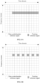
- one transmission slot is 14 OFDM symbols (numbered from 0 to 13), and OFDM symbols to which the PTRS may be mapped are numbered from 3 to 13.
- FIG. 6A and FIG. 6B two specific embodiments are provided in FIG. 6A and FIG. 6B , and respectively correspond to an example in which the PTRS is mapped to all the OFDM symbols to which the PTRS may be mapped in time domain and an example in which the PTRS occupies only about half the OFDM symbols.
- Embodiment 1 Establish a one-to-one correspondence between subcarrier spacings SCs and time domain densities.
- Density indicates the time domain density. For example, if a value of Density is 1/3, it indicates that one PTRS is mapped to every three OFDM symbols.
- SC indicates a current subcarrier spacing
- SC 0 is a reference subcarrier spacing
- ⁇ 0 is a constant
- ⁇ ⁇ and ⁇ ⁇ respectively indicate rounding down and rounding up.
- the time domain density is greater than or equal to 1/total quantity of symbols and less than or equal to 1.
- Density is directly set to 1, to be specific, the PTRS is mapped to all symbols.
- Density is less than 1/total quantity of symbols, Density is directly set to 1/total quantity of symbols, to be specific, the PTRS is mapped to only one of the symbols.
- the total quantity of symbols is a total quantity of symbols to which the PTRS may be mapped in one slot. Details are not described repeatedly below.
- the PTRS needs to be mapped to two OFDM symbols, and the PTRS may be mapped to two of the symbols according to a preset rule.
- the preset rule may be mapping the PTRS to first two symbols, or mapping the PTRS to a symbol 4 and a symbol 9, or mapping the PTRS based on an algorithm or a formula.
- the preset rule may be prestored on the transmit device and the receive device.
- the receive device may determine a specific time-frequency location of the PTRS according to the prestored rule.
- the time domain density may also be corrected based on the modulation and coding scheme (MCS). Specifically, the time domain density may be adjusted by correcting a value of ⁇ 0 .
- MCSs may be classified into x levels, and x is greater than or equal to 1.
- Each MCS level corresponds to one value of ⁇ , as shown in Table 4.
- a system may obtain a PTRS time domain density of the current slot based on the preset table of the correspondence between the SC and the time domain density with reference to the MCS level, as shown in Table 4.
- Table 4 MCS level 0 1 ... X MCS interval [MCS 0 , MCS 1 ) [MCS 1 , MCS 2 ) ... [MCS x-1 , MCS x ) Adjustment factor ⁇ 0 ⁇ 1 ... ⁇ x
- MCS interval classification in Table 4 is merely an example, and intervals may be (MCS 0 , MCS 1 ], (MCS 1 , MCS 2 ], (MCS 2 , MCS 3 ], and the like. This is not limited in the present invention.
- Embodiment 2 Establish a one-to-one correspondence between time domain densities and SCs.
- SCs may be classified into K levels, each level corresponds to one SC interval, and a subcarrier spacing interval corresponding to a level k is (SC k-1 , SC k ].
- one SC level corresponds to one time domain density.
- Table 5 provides a specific example for SC levels and time domain densities. Table 5 SC level 1 2 3 ... SC interval ⁇ 60 k [60 k, 120 k) [120 k, 240 k) ... Time domain density 1 1/2 1/4 ...
- a system may obtain a PTRS time domain density of the current slot based on the preset table of the correspondence between the SC and the time domain density with reference to the MCS level, as shown in Table 6.
- Table 6 MCS level -x ... 0 1 ... x MCS interval [MCS 0 , MCS 1 ) ... [MCS m , MCS m+1 ) [MCS m+1 , MCS m+2 ) ... [MCS x-1 , MCS x ) SC level correction amount -y ... 0 1 ... y
- higher layer signaling may also be used to instruct to adjust a correspondence, in a solution, between an MCS level and an MCS interval corresponding to the MCS level and/or to adjust a correspondence between an SC level and an SC interval corresponding to the SC level, to adapt to a new scenario and condition.
- quantities or a quantity of levels by which the MCS level and/or the SC level shown in Table 5 or Table 6 are/is increased or decreased may be directly adjusted by using higher layer signaling.
- the receive device may determine a time-frequency location of the PTRS in the one or more OFDM symbols in the following manner:
- mapping rules between a PTRS frequency domain mapping pattern and the MCS and/or the BW.
- the following uses a plurality of embodiments for description.
- Embodiment 3 Establish a correspondence between the BW and a quantity of PTRS frequency domains.
- the preset rule may be specified in the standard and preconfigured or prestored on the transmit device and the receive device.
- Embodiment 4 Establish a correspondence between the BW and a PTRS frequency domain density T.
- the frequency domain density is used to indicate a PTRS density or the quantity of PTRS frequency domains on each scheduled bandwidth.
- higher layer signaling may be used to instruct to adjust a correspondence, in a solution, between a BW level and a BW interval corresponding to the BW level.
- the BW level may be directly increased or decreased by x levels through adjustment by using higher layer signaling, where x is an integer less than or equal to K.
- BWs are classified into K levels (columns in Table 9), and MCSs are classified into M levels (rows in Table 9), to obtain a correspondence table of K*M dimensions, as shown in Table 9.
- T 23 indicates the quantity of PTRS frequency domains
- an integer obtained after T 23 is rounded up or rounded down indicates the quantity of PTRS frequency domains.
- T 23 may not be rounded.
- the preset rule may be mapping T 23 PTRSs at equal intervals starting from a first subcarrier, or consecutively mapping T 23 PTRSs starting from a fifth subcarrier, or mapping one PTRS every other subcarrier starting from a first subcarrier until all PTRSs are mapped.
- higher layer signaling may be used to instruct to adjust a correspondence, in a solution, between a BW level and a BW interval corresponding to the BW level, or instruct to adjust a correspondence, in a solution, between an MCS level and an MCS interval corresponding to the MCS level, or instruct to adjust both a correspondence between a BW level and a BW interval corresponding to the BW level and a correspondence between an MCS level and an MCS interval corresponding to the MCS level.
- the BW level and/or the MCS level may be directly increased or decreased by X or Y levels through configuration by using higher layer signaling. X and Y are integers greater than 0.
- the receive device may determine a time-frequency location of the PTRS in the one or more OFDM symbols in the following manner:
- the receive device may obtain PTRS-related configuration information by using information such as the MCS, the BW, and the SC. This can reduce signaling overheads in comparison with the prior art.
- the processor 810 controls an operation of the transmit device 800, and the processor may be a general-purpose processor, a digital signal processor, a dedicated integrated circuit, a field programmable gate array, or another programmable logic device.
- the bus 850 includes a power bus, a control bus, and a status signal bus.
- various buses are marked as the bus 850 in the figure. It should be noted that the foregoing descriptions about the transmit device structure may be applied to the embodiments of the present invention.
- the processor 810 is configured to map a PTRS to one or more OFDM symbols based on information about a correspondence between the PTRS and one or more of a modulation and coding scheme (MCS), a bandwidth (BW), and a subcarrier spacing (SC).
- MCS modulation and coding scheme
- BW bandwidth
- SC subcarrier spacing
- the processor 810 is further configured to determine to map the phase tracking reference signal (PTRS) to the one or more orthogonal frequency division multiplexing (OFDM) symbols.
- PTRS phase tracking reference signal
- OFDM orthogonal frequency division multiplexing
- the memory 820 is configured to prestore a correspondence between the bandwidth and a quantity of PTRS frequency domains or a PTRS frequency domain density.
- the transmit device shown in FIG. 8 may be a base station or a terminal.
- the transmit device shown in FIG. 8 corresponds to the transmit device in the foregoing method embodiment, and descriptions about all details of the method embodiment may be used to explain the apparatus embodiment of the transmit device.
- the transmit device and the receive device refer to the foregoing description. Details are not described again.
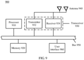
- the processor 910 controls an operation of the receive device 900, and the processor may be a general-purpose processor, a digital signal processor, a dedicated integrated circuit, a field programmable gate array, or another programmable logic device.
- the transceiver 930 includes a transmitter 932 and a receiver 934, the transmitter 932 is configured to transmit a signal, and the receiver 934 is configured to receive a signal. There may be one or more antennas 940.
- the receive device 900 may further include the user interface 960 such as a keyboard, a microphone, a loudspeaker, and/or a touchscreen. The user interface 960 may transfer content and a control operation to the receive device 900.
- the bus 950 includes a power bus, a control bus, and a status signal bus.
- various buses are marked as the bus 950 in the figure. It should be noted that the foregoing descriptions about a network element structure may be applied to the embodiments of the present invention.
- the memory 920 may include a read-only memory (Read-Only Memory, ROM), a random access memory (Random Access Memory, RAM), or another type of dynamic storage device that may store information and an instruction, or may be a magnetic disk storage.
- the memory 920 may be configured to store an instruction for implementing the related method provided in the embodiments of the present invention. It may be understood that an executable instruction is programmed or loaded into at least one of the processor 910, a cache, and a long term memory of the receive device 900.
- the memory is configured to store computer executable program code. When the program code includes an instruction, and the processor executes the instruction, the instruction enables the receive device to perform the following operations:
- the transceiver 930 is configured to receive one or more orthogonal frequency division multiplexing (OFDM) symbols from a transmit device.
- OFDM orthogonal frequency division multiplexing
- the processor 910 is configured to determine a phase tracking reference signal (PTRS) from the one or more OFDM symbols based on information about a correspondence between the PTRS and one or more of a modulation and coding scheme (MCS), a bandwidth (BW), and a subcarrier spacing (SC).
- PTRS phase tracking reference signal
- processor 910 is specifically configured to:
- the memory 920 is configured to prestore information about a correspondence between the subcarrier spacing (SC) or the modulation and coding scheme (MCS) and a PTRS time domain density, where the PTRS time domain density is used to indicate that one PTRS is mapped to every several OFDM symbols.
- SC subcarrier spacing
- MCS modulation and coding scheme
- processor 910 is specifically configured to:
- the memory 920 is configured to prestore a correspondence between the modulation and coding scheme (MCS) and a quantity of PTRS frequency domains or a PTRS frequency domain density.
- MCS modulation and coding scheme
- the memory 920 is further configured to prestore a correspondence between both the modulation and coding scheme (MCS) and the bandwidth (BW) and a quantity of PTRS frequency domains.
- MCS modulation and coding scheme
- BW bandwidth
- the receive device shown in FIG. 9 corresponds to the receive device in the foregoing method embodiment, and descriptions about all details of the method embodiment may be used to explain the apparatus embodiment of the receive device.
- the transmit device and the receive device refer to the foregoing description. Details are not described again.
- An embodiment of the present invention further provides a computer storage medium, configured to store a computer software instruction used by a transmit device.
- the computer software instruction includes a program designed for performing the foregoing embodiment.
- An embodiment of the present invention further provides a computer storage medium, configured to store a computer software instruction used by the foregoing receive device.
- the computer software instruction includes a program designed for performing the foregoing embodiment.
- the transmit device is configured to perform steps performed by the transmit device in the method embodiment.
- the subcarrier spacing or the modulation and coding scheme or the bandwidth is used to implicitly indicate the time-frequency location of the PTRS, so that no explicit DCI indication is required. In comparison with the prior art, signaling overheads are reduced.
- the usable medium may be a magnetic medium (for example, a floppy disk, a hard disk, or a magnetic tape), an optical medium (for example, a DVD), a semiconductor medium (for example, a solid state disk Solid State Disk, (SSD)), or the like.
- a magnetic medium for example, a floppy disk, a hard disk, or a magnetic tape
- an optical medium for example, a DVD
- a semiconductor medium for example, a solid state disk Solid State Disk, (SSD)
Landscapes
- Engineering & Computer Science (AREA)
- Signal Processing (AREA)
- Computer Networks & Wireless Communication (AREA)
- Quality & Reliability (AREA)
- Mobile Radio Communication Systems (AREA)
- Optical Communication System (AREA)
- Two-Way Televisions, Distribution Of Moving Picture Or The Like (AREA)
Claims (11)
- Referenzsignalübertragungsverfahren, durchgeführt durch eine Übertragungsvorrichtung, umfassend:Bestimmen einer Zeitbereichsdichte eines Phasenverfolgungsreferenzsignals bzw. PTRS basierend auf einem Modulations- und Codierungsschema bzw. MCS und einer Entsprechung zwischen MCS und PTRS-Zeitbereichsdichte;Bestimmen einer Frequenzbereichsdichte des PTRS basierend auf einer geplanten Bandbreite und einer Entsprechung zwischen geplanter Bandbreite und PTRS-Frequenzbereichsdichte;Abbilden (S502) des PTRS auf ein oder mehrere Orthogonalfrequenzmultiplex- bzw. OFDM-Symbole gemäß der Zeitbereichsdichte des PTRS und der Frequenzbereichsdichte des PTRS; undSenden (S504) des PTRS, das auf das eine oder die mehreren OFDM-Symbole abgebildet wird, an eine Empfangsvorrichtung;wobei die Entsprechung zwischen MCS und PTRS-Zeitbereichsdichte Folgendes umfasst:unterschiedliche MCS-Intervalle entsprechen unterschiedlichen PTRS-Zeitbereichsdichten;wobei die Entsprechung zwischen geplanter Bandbreite und PTRS-Frequenzbereichsdichte Folgendes umfasst:
unterschiedliche Intervalle geplanter Bandbreite entsprechen unterschiedlichen PTRS-Frequenzbereichsdichten. - Verfahren nach Anspruch 1, ferner umfassend:wenn das MCS kleiner als eine erste Schwelle ist, Nicht-Abbilden des PTRS; oderwenn die geplante Bandbreite kleiner als eine zweite Schwelle ist, Nicht-Abbilden des PTRS.
- Verfahren nach Anspruch 2, ferner umfassend:
Empfangen der ersten oder der zweiten Schwelle über eine Signalisierung höherer Schicht. - Verfahren nach Anspruch 1, wobei:
die Entsprechung zwischen MCS und PTRS-Zeitbereichsdichte und die Entsprechung zwischen geplanter Bandbreite und PTRS-Frequenzbereichsdichte vorkonfiguriert oder vorgespeichert sind. - Referenzsignalempfangsverfahren, durchgeführt durch eine Empfangsvorrichtung, umfassend:Empfangen (S506) eines oder mehrerer Orthogonalfrequenzmultiplex- bzw. OFDM-Symbole von einer Übertragungsvorrichtung;Bestimmen einer Zeitbereichsdichte eines Phasenverfolgungsreferenzsignals bzw. PTRS basierend auf einem Modulations- und Codierungsschema bzw. MCS und einer Entsprechung zwischen MCS und PTRS-Zeitbereichsdichte;Bestimmen einer Frequenzbereichsdichte des PTRS basierend auf einer geplanten Bandbreite und einer Entsprechung zwischen geplanter Bandbreite und PTRS-Frequenzbereichsdichte; undBestimmen (S506) des Phasenverfolgungsreferenzsignals bzw. PTRS anhand des einen oder der mehreren OFDM-Symbole basierend auf der Zeitbereichsdichte des PTRS und der Frequenzbereichsdichte des PTRS;wobei die Entsprechung zwischen MCS und PTRS-Zeitbereichsdichte Folgendes umfasst:unterschiedliche MCS-Intervalle entsprechen unterschiedlichen PTRS-Zeitbereichsdichten;wobei die Entsprechung zwischen geplanter Bandbreite und PTRS-Frequenzbereichsdichte Folgendes umfasst:
unterschiedliche Intervalle geplanter Bandbreite entsprechen unterschiedlichen PTRS-Frequenzbereichsdichten. - Verfahren nach Anspruch 5, wobei das Bestimmen des PTRS anhand des einen oder der mehreren OFDM-Symbole insbesondere Folgendes umfasst:
Bestimmen einer Zeit-Frequenz-Position des PTRS in dem einen oder den mehreren OFDM-Symbolen basierend auf der Zeitbereichsdichte des PTRS und der Frequenzbereichsdichte des PTRS. - Verfahren nach Anspruch 5, wobei:
die Entsprechung zwischen MCS und PTRS-Zeitbereichsdichte und die Entsprechung zwischen geplanter Bandbreite und PTRS-Frequenzbereichsdichte vorkonfiguriert oder vorgespeichert sind. - Übertragungsvorrichtung, ausgelegt zum Durchführen des Verfahrens nach einem der Ansprüche 1-4.
- Empfangsvorrichtung, ausgelegt zum Durchführen des Verfahrens nach einem der Ansprüche 5-7.
- Computerlesbares Speichermedium, wobei ein Computerprogramm in dem computerlesbaren Speichermedium gespeichert ist und bei Ausführung des Programms das Verfahren nach einem der Ansprüche 1 bis 4 oder 5-7 implementiert wird.
- Computerprogrammprodukt, das Anweisungen umfasst, wobei bei Ausführung der Anweisungen auf einer Rechenvorrichtung das Verfahren nach einem der Ansprüche 1 bis 4 oder 5-7 durch die Rechenvorrichtung durchgeführt wird.
Applications Claiming Priority (3)
| Application Number | Priority Date | Filing Date | Title |
|---|---|---|---|
| CN201710011404.4A CN108282877B (zh) | 2017-01-06 | 2017-01-06 | 一种参考信号的配置方法、装置及系统 |
| EP17889676.7A EP3407523B1 (de) | 2017-01-06 | 2017-10-20 | Referenzsignalkonfigurationsverfahren, -vorrichtung und -system |
| PCT/CN2017/107135 WO2018126763A1 (zh) | 2017-01-06 | 2017-10-20 | 一种参考信号的配置方法、装置及系统 |
Related Parent Applications (2)
| Application Number | Title | Priority Date | Filing Date |
|---|---|---|---|
| EP17889676.7A Division EP3407523B1 (de) | 2017-01-06 | 2017-10-20 | Referenzsignalkonfigurationsverfahren, -vorrichtung und -system |
| EP17889676.7A Division-Into EP3407523B1 (de) | 2017-01-06 | 2017-10-20 | Referenzsignalkonfigurationsverfahren, -vorrichtung und -system |
Publications (3)
| Publication Number | Publication Date |
|---|---|
| EP3852299A1 EP3852299A1 (de) | 2021-07-21 |
| EP3852299B1 true EP3852299B1 (de) | 2025-04-09 |
| EP3852299C0 EP3852299C0 (de) | 2025-04-09 |
Family
ID=62789064
Family Applications (2)
| Application Number | Title | Priority Date | Filing Date |
|---|---|---|---|
| EP20212106.7A Active EP3852299B1 (de) | 2017-01-06 | 2017-10-20 | Referenzsignalkonfigurationsverfahren und -vorrichtung |
| EP17889676.7A Active EP3407523B1 (de) | 2017-01-06 | 2017-10-20 | Referenzsignalkonfigurationsverfahren, -vorrichtung und -system |
Family Applications After (1)
| Application Number | Title | Priority Date | Filing Date |
|---|---|---|---|
| EP17889676.7A Active EP3407523B1 (de) | 2017-01-06 | 2017-10-20 | Referenzsignalkonfigurationsverfahren, -vorrichtung und -system |
Country Status (9)
| Country | Link |
|---|---|
| US (3) | US10727998B2 (de) |
| EP (2) | EP3852299B1 (de) |
| JP (1) | JP7055540B2 (de) |
| KR (1) | KR102392464B1 (de) |
| CN (3) | CN112654089B (de) |
| BR (1) | BR112019014145B8 (de) |
| CA (1) | CA3049495C (de) |
| ES (1) | ES3027675T3 (de) |
| WO (1) | WO2018126763A1 (de) |
Families Citing this family (41)
| Publication number | Priority date | Publication date | Assignee | Title |
|---|---|---|---|---|
| CN108289021B (zh) * | 2017-01-09 | 2021-10-01 | 华为技术有限公司 | 参考信号的传输方法和设备 |
| US10608800B2 (en) * | 2017-01-09 | 2020-03-31 | Lg Electronics Inc. | Method for transmitting reference signal and device therefor in wireless communication system |
| JP2020057827A (ja) * | 2017-02-02 | 2020-04-09 | シャープ株式会社 | 基地局装置、端末装置、通信方法、および、集積回路 |
| CN115622674B (zh) * | 2017-02-07 | 2024-12-24 | 中兴通讯股份有限公司 | 一种相位噪声导频的配置、确定方法及装置 |
| CN110169025B (zh) | 2017-03-08 | 2021-09-07 | 松下电器(美国)知识产权公司 | 发送装置、接收装置、发送方法及接收方法 |
| KR101980715B1 (ko) | 2017-03-25 | 2019-05-21 | 엘지전자 주식회사 | 무선 통신 시스템에서 단말의 위상 트래킹 참조 신호 수신 방법 및 이를 지원하는 장치 |
| US10554359B2 (en) * | 2017-03-25 | 2020-02-04 | Lg Electronics Inc. | Method of receiving phase tracking reference signal by user equipment in wireless communication system and device for supporting same |
| JP2020109882A (ja) * | 2017-04-27 | 2020-07-16 | シャープ株式会社 | 基地局装置、端末装置、通信方法、および、集積回路 |
| US11283557B2 (en) * | 2017-04-28 | 2022-03-22 | Panasonic Intellectual Property Corporation Of America | Measurement apparatus and measurement method |
| CN108809601B (zh) | 2017-05-04 | 2023-10-24 | 华为技术有限公司 | 无线通信方法及装置 |
| CN108809598B (zh) | 2017-05-05 | 2023-10-20 | 华为技术有限公司 | 一种通信方法及装置 |
| WO2018225927A1 (ko) * | 2017-06-09 | 2018-12-13 | 엘지전자(주) | 무선 통신 시스템에서 참조 신호를 송수신하기 위한 방법 및 이를 위한 장치 |
| KR102396952B1 (ko) | 2017-06-15 | 2022-05-13 | 삼성전자 주식회사 | 차세대 통신 시스템에서 ptrs를 할당하는 방법 및 장치 |
| WO2018230900A1 (en) * | 2017-06-15 | 2018-12-20 | Samsung Electronics Co., Ltd. | Method and apparatus for allocating ptrs in next generation communication system |
| US11641299B2 (en) * | 2017-09-07 | 2023-05-02 | Apple Inc. | Phase tracking reference signal (PT-RS) configuration |
| US10715369B2 (en) * | 2017-10-11 | 2020-07-14 | Qualcomm Incorporated | Phase tracking reference signal |
| JP7218756B2 (ja) * | 2017-11-09 | 2023-02-07 | 日本電気株式会社 | 端末、ネットワーク装置、及び方法 |
| CN110034904B (zh) * | 2018-01-11 | 2022-01-04 | 维沃移动通信有限公司 | 相位跟踪参考信号关联指示及发送方法、网络设备和终端 |
| CN110034891B (zh) | 2018-01-12 | 2020-10-20 | 电信科学技术研究院有限公司 | 一种系统信息配置方法和装置 |
| GB2573564A (en) | 2018-05-11 | 2019-11-13 | Samsung Electronics Co Ltd | Improvements in and relating to reference signals in a telecommunication network |
| US10863520B2 (en) * | 2018-05-11 | 2020-12-08 | Qualcomm Incorporated | Reference signal tone location shift |
| WO2020035956A1 (ja) * | 2018-08-17 | 2020-02-20 | 株式会社Nttドコモ | ユーザ端末及び無線通信方法 |
| CN110855406B (zh) * | 2018-08-20 | 2022-05-03 | 大唐移动通信设备有限公司 | 相位跟踪参考信号ptrs传输方法、网络设备及终端 |
| CN109257308B (zh) * | 2018-09-19 | 2021-01-05 | 中国联合网络通信集团有限公司 | 一种相位噪声估计方法及装置 |
| CN110536229B (zh) * | 2018-09-28 | 2023-03-28 | 中兴通讯股份有限公司 | 一种参考信号配置及定位方法、装置、存储介质 |
| CN111130728B (zh) * | 2018-10-31 | 2023-08-25 | 维沃移动通信有限公司 | 一种传输方法、终端及网络侧设备 |
| EP3903439A4 (de) | 2019-03-14 | 2022-10-05 | Apple Inc. | Systeme und verfahren zur phasennachführung einer referenzsignalübertragung für ofdm |
| WO2020237452A1 (en) * | 2019-05-27 | 2020-12-03 | Qualcomm Incorporated | Phase tracking reference signal configuration for a random access procedure |
| CN112566010B (zh) * | 2019-09-26 | 2022-03-29 | 大唐移动通信设备有限公司 | 一种信号发送、接收方法、网络设备及终端设备 |
| CN112583759B (zh) * | 2019-09-27 | 2022-04-22 | 华为技术有限公司 | 信息传输方法及通信装置 |
| WO2021066630A1 (ko) * | 2019-10-03 | 2021-04-08 | 엘지전자 주식회사 | 무선 통신 시스템에서 위상 추적 참조 신호의 송수신 방법 및 이에 대한 장치 |
| KR102553638B1 (ko) | 2019-10-03 | 2023-07-11 | 엘지전자 주식회사 | 무선 통신 시스템에서 위상 추적 참조 신호의 송수신 방법 및 이에 대한 장치 |
| US11924015B2 (en) | 2019-10-04 | 2024-03-05 | Qualcomm Incorporated | Phase tracking reference signal for multi-transmit/receive points |
| WO2021187637A1 (ko) * | 2020-03-18 | 2021-09-23 | 엘지전자 주식회사 | 위상 잡음 제거 방법 및 장치 |
| WO2021217374A1 (zh) * | 2020-04-27 | 2021-11-04 | 北京小米移动软件有限公司 | 链路自适应参数指示以及链路自适应参数确定方法和装置 |
| US12058066B2 (en) * | 2020-05-13 | 2024-08-06 | Qualcomm Incorporated | Phase tracking reference signal (PTRS) allocation for multi-symbol demodulation reference signals (DMRS) |
| CN114374483A (zh) * | 2020-10-14 | 2022-04-19 | 夏普株式会社 | 由用户设备执行的方法以及用户设备 |
| US11588597B2 (en) * | 2020-11-09 | 2023-02-21 | Qualcomm Incorporated | Determining a density of a phase tracking reference signal |
| WO2022216190A1 (en) * | 2021-04-07 | 2022-10-13 | Telefonaktiebolaget Lm Ericsson (Publ) | Phase tracking reference signalling |
| CN115913853A (zh) * | 2021-08-05 | 2023-04-04 | 华为技术有限公司 | 一种相位跟踪参考信号的传输方法及装置 |
| CN119496535A (zh) * | 2023-08-18 | 2025-02-21 | 华为技术有限公司 | 一种物理上行共享信道传输的预编码方法及装置 |
Family Cites Families (16)
| Publication number | Priority date | Publication date | Assignee | Title |
|---|---|---|---|---|
| JP4952607B2 (ja) | 2008-02-08 | 2012-06-13 | 三菱電機株式会社 | 衛星間基準信号同期システム、親衛星及び子衛星 |
| JP4930424B2 (ja) | 2008-03-24 | 2012-05-16 | 富士通株式会社 | 位相トラッキング回路、無線受信機、信号処理方法、及び信号処理に用いるプログラム |
| US8730850B2 (en) * | 2009-09-17 | 2014-05-20 | Lg Electronics Inc. | Method and apparatus for transmitting reference signal in time division duplex system |
| US9288096B2 (en) | 2009-12-07 | 2016-03-15 | Qualcomm Incorporated | Enabling phase tracking for a communication device |
| EP2343849B1 (de) | 2010-01-07 | 2019-05-29 | Samsung Electronics Co., Ltd. | Vorrichtung und Verfahren zur Erweiterung der Merkmale von Uplink-Referenzsignalen |
| US9025428B2 (en) * | 2010-04-14 | 2015-05-05 | Qualcomm Incorporated | Allocating and receiving tones for a frame |
| CN102739382A (zh) * | 2011-03-25 | 2012-10-17 | 北京新岸线无线技术有限公司 | 无线通信系统中解调导频的调整方法及系统 |
| CN108809364B (zh) * | 2011-09-30 | 2022-03-29 | 交互数字专利控股公司 | 用于无线通信系统中的多点传输的方法及装置 |
| US9179496B2 (en) | 2012-04-02 | 2015-11-03 | Qualcomm Incorporated | Tone scaling parameters in Sub-1 GHz networks |
| US9774481B2 (en) | 2012-04-05 | 2017-09-26 | Qualcomm, Incorporated | Systems and methods for transmitting pilot tones |
| US9461855B2 (en) | 2012-07-05 | 2016-10-04 | Intel Corporation | Methods and arrangements for selecting channel updates in wireless networks |
| US9313059B2 (en) | 2012-12-21 | 2016-04-12 | Qualcomm Incorporated | Data-modulated pilots for phase and gain detectors |
| EP2945443A4 (de) * | 2013-01-08 | 2016-07-06 | Fujitsu Ltd | Demodulationsreferenzsignalkonfiguration und mappingverfahren, kanalschätzungsverfahren und vorrichtung |
| US10367672B2 (en) * | 2016-09-28 | 2019-07-30 | Qualcomm Incorporated | Enhancements to phase-noise compensation reference signal design and scrambling |
| JP6640428B2 (ja) * | 2016-09-30 | 2020-02-05 | エルジー エレクトロニクス インコーポレイティド | 位相雑音推定に関連する参照信号のための制御情報を受信する方法及びそのための端末 |
| KR102272818B1 (ko) * | 2017-05-04 | 2021-07-05 | 삼성전자 주식회사 | 무선 통신 시스템에서 효율적인 ptrs 운영 및 지시에 관한 장치 및 방법 |
-
2017
- 2017-01-06 CN CN202011363402.XA patent/CN112654089B/zh active Active
- 2017-01-06 CN CN201710011404.4A patent/CN108282877B/zh active Active
- 2017-01-06 CN CN201810446511.4A patent/CN108737058B/zh active Active
- 2017-10-20 EP EP20212106.7A patent/EP3852299B1/de active Active
- 2017-10-20 ES ES20212106T patent/ES3027675T3/es active Active
- 2017-10-20 KR KR1020197022948A patent/KR102392464B1/ko active Active
- 2017-10-20 JP JP2019537060A patent/JP7055540B2/ja active Active
- 2017-10-20 BR BR112019014145A patent/BR112019014145B8/pt active Search and Examination
- 2017-10-20 CA CA3049495A patent/CA3049495C/en active Active
- 2017-10-20 EP EP17889676.7A patent/EP3407523B1/de active Active
- 2017-10-20 WO PCT/CN2017/107135 patent/WO2018126763A1/zh not_active Ceased
-
2018
- 2018-08-31 US US16/118,657 patent/US10727998B2/en active Active
-
2020
- 2020-03-03 US US16/808,341 patent/US11362781B2/en active Active
-
2022
- 2022-05-26 US US17/825,879 patent/US11764928B2/en active Active
Also Published As
| Publication number | Publication date |
|---|---|
| CN108282877A (zh) | 2018-07-13 |
| US20180367277A1 (en) | 2018-12-20 |
| KR102392464B1 (ko) | 2022-04-28 |
| JP7055540B2 (ja) | 2022-04-18 |
| CN108737058A (zh) | 2018-11-02 |
| CN112654089B (zh) | 2022-02-25 |
| ES3027675T3 (en) | 2025-06-16 |
| CN108282877B (zh) | 2023-12-01 |
| EP3407523A4 (de) | 2019-04-03 |
| EP3407523A1 (de) | 2018-11-28 |
| CA3049495C (en) | 2024-02-27 |
| US20200204321A1 (en) | 2020-06-25 |
| US11362781B2 (en) | 2022-06-14 |
| EP3852299C0 (de) | 2025-04-09 |
| CN108737058B (zh) | 2019-07-12 |
| US10727998B2 (en) | 2020-07-28 |
| WO2018126763A1 (zh) | 2018-07-12 |
| BR112019014145B1 (pt) | 2022-03-29 |
| KR20190101454A (ko) | 2019-08-30 |
| CN112654089A (zh) | 2021-04-13 |
| BR112019014145A2 (pt) | 2020-02-11 |
| BR112019014145B8 (pt) | 2022-07-12 |
| US20220393821A1 (en) | 2022-12-08 |
| JP2020504554A (ja) | 2020-02-06 |
| EP3852299A1 (de) | 2021-07-21 |
| US11764928B2 (en) | 2023-09-19 |
| CA3049495A1 (en) | 2018-07-12 |
| EP3407523B1 (de) | 2021-01-27 |
Similar Documents
| Publication | Publication Date | Title |
|---|---|---|
| EP3852299B1 (de) | Referenzsignalkonfigurationsverfahren und -vorrichtung | |
| US12057933B2 (en) | Scheduling in communication systems with multiple service types | |
| US11082150B2 (en) | Wireless communication method and apparatus for mapping a phase tracking reference signal based on a target modulation and coding scheme index | |
| US10390337B2 (en) | Aperiodic channel state information (CSI) reporting for carrier aggregation | |
| US11082179B2 (en) | Reference signal sending method and communications device | |
| US10904051B2 (en) | Method for sending carrier information, base station, and terminal | |
| US11330536B2 (en) | Apparatus and method for controlling gain of received signal in wireless communication system | |
| CN111435892B (zh) | 接收数据的方法和装置 | |
| EP4152811A1 (de) | Verfahren und vorrichtung zur cache-bestimmung | |
| EP4654729A1 (de) | Drahtloskommunikationsverfahren, endgerätevorrichtung und netzwerkvorrichtung | |
| EP3528446B1 (de) | Empfang von referenzsignalen in einem kommunikationssystem mit verschiedenen fft-längen | |
| US20250227689A1 (en) | Transport block size determination in communication networks | |
| US20250226954A1 (en) | Transport block size determination in communication networks | |
| US20250330282A1 (en) | Device and method for supporting communication using plurality of bandwidths in wireless local area network system | |
| KR20240047290A (ko) | Wlan 시스템에서 복수의 대역폭들을 이용한 통신을 지원하는 장치 및 방법 | |
| EP4672687A1 (de) | Informationsübertragungsverfahren und -vorrichtung |
Legal Events
| Date | Code | Title | Description |
|---|---|---|---|
| PUAI | Public reference made under article 153(3) epc to a published international application that has entered the european phase |
Free format text: ORIGINAL CODE: 0009012 |
|
| STAA | Information on the status of an ep patent application or granted ep patent |
Free format text: STATUS: REQUEST FOR EXAMINATION WAS MADE |
|
| 17P | Request for examination filed |
Effective date: 20201207 |
|
| AC | Divisional application: reference to earlier application |
Ref document number: 3407523 Country of ref document: EP Kind code of ref document: P |
|
| AK | Designated contracting states |
Kind code of ref document: A1 Designated state(s): AL AT BE BG CH CY CZ DE DK EE ES FI FR GB GR HR HU IE IS IT LI LT LU LV MC MK MT NL NO PL PT RO RS SE SI SK SM TR |
|
| GRAP | Despatch of communication of intention to grant a patent |
Free format text: ORIGINAL CODE: EPIDOSNIGR1 |
|
| STAA | Information on the status of an ep patent application or granted ep patent |
Free format text: STATUS: GRANT OF PATENT IS INTENDED |
|
| INTG | Intention to grant announced |
Effective date: 20241105 |
|
| GRAS | Grant fee paid |
Free format text: ORIGINAL CODE: EPIDOSNIGR3 |
|
| GRAA | (expected) grant |
Free format text: ORIGINAL CODE: 0009210 |
|
| STAA | Information on the status of an ep patent application or granted ep patent |
Free format text: STATUS: THE PATENT HAS BEEN GRANTED |
|
| AC | Divisional application: reference to earlier application |
Ref document number: 3407523 Country of ref document: EP Kind code of ref document: P |
|
| AK | Designated contracting states |
Kind code of ref document: B1 Designated state(s): AL AT BE BG CH CY CZ DE DK EE ES FI FR GB GR HR HU IE IS IT LI LT LU LV MC MK MT NL NO PL PT RO RS SE SI SK SM TR |
|
| REG | Reference to a national code |
Ref country code: GB Ref legal event code: FG4D |
|
| REG | Reference to a national code |
Ref country code: CH Ref legal event code: EP |
|
| REG | Reference to a national code |
Ref country code: IE Ref legal event code: FG4D |
|
| U01 | Request for unitary effect filed |
Effective date: 20250409 |
|
| U07 | Unitary effect registered |
Designated state(s): AT BE BG DE DK EE FI FR IT LT LU LV MT NL PT RO SE SI Effective date: 20250415 |
|
| REG | Reference to a national code |
Ref country code: ES Ref legal event code: FG2A Ref document number: 3027675 Country of ref document: ES Kind code of ref document: T3 Effective date: 20250616 |
|
| PG25 | Lapsed in a contracting state [announced via postgrant information from national office to epo] |
Ref country code: GR Free format text: LAPSE BECAUSE OF FAILURE TO SUBMIT A TRANSLATION OF THE DESCRIPTION OR TO PAY THE FEE WITHIN THE PRESCRIBED TIME-LIMIT Effective date: 20250710 Ref country code: NO Free format text: LAPSE BECAUSE OF FAILURE TO SUBMIT A TRANSLATION OF THE DESCRIPTION OR TO PAY THE FEE WITHIN THE PRESCRIBED TIME-LIMIT Effective date: 20250709 |
|
| PG25 | Lapsed in a contracting state [announced via postgrant information from national office to epo] |
Ref country code: PL Free format text: LAPSE BECAUSE OF FAILURE TO SUBMIT A TRANSLATION OF THE DESCRIPTION OR TO PAY THE FEE WITHIN THE PRESCRIBED TIME-LIMIT Effective date: 20250409 |
|
| PG25 | Lapsed in a contracting state [announced via postgrant information from national office to epo] |
Ref country code: HR Free format text: LAPSE BECAUSE OF FAILURE TO SUBMIT A TRANSLATION OF THE DESCRIPTION OR TO PAY THE FEE WITHIN THE PRESCRIBED TIME-LIMIT Effective date: 20250409 |
|
| PG25 | Lapsed in a contracting state [announced via postgrant information from national office to epo] |
Ref country code: RS Free format text: LAPSE BECAUSE OF FAILURE TO SUBMIT A TRANSLATION OF THE DESCRIPTION OR TO PAY THE FEE WITHIN THE PRESCRIBED TIME-LIMIT Effective date: 20250709 |
|
| PG25 | Lapsed in a contracting state [announced via postgrant information from national office to epo] |
Ref country code: IS Free format text: LAPSE BECAUSE OF FAILURE TO SUBMIT A TRANSLATION OF THE DESCRIPTION OR TO PAY THE FEE WITHIN THE PRESCRIBED TIME-LIMIT Effective date: 20250809 |
|
| U20 | Renewal fee for the european patent with unitary effect paid |
Year of fee payment: 9 Effective date: 20251031 |
|
| PG25 | Lapsed in a contracting state [announced via postgrant information from national office to epo] |
Ref country code: SM Free format text: LAPSE BECAUSE OF FAILURE TO SUBMIT A TRANSLATION OF THE DESCRIPTION OR TO PAY THE FEE WITHIN THE PRESCRIBED TIME-LIMIT Effective date: 20250409 |
|
| PG25 | Lapsed in a contracting state [announced via postgrant information from national office to epo] |
Ref country code: CZ Free format text: LAPSE BECAUSE OF FAILURE TO SUBMIT A TRANSLATION OF THE DESCRIPTION OR TO PAY THE FEE WITHIN THE PRESCRIBED TIME-LIMIT Effective date: 20250409 |
|
| PG25 | Lapsed in a contracting state [announced via postgrant information from national office to epo] |
Ref country code: SK Free format text: LAPSE BECAUSE OF FAILURE TO SUBMIT A TRANSLATION OF THE DESCRIPTION OR TO PAY THE FEE WITHIN THE PRESCRIBED TIME-LIMIT Effective date: 20250409 |
|
| PGFP | Annual fee paid to national office [announced via postgrant information from national office to epo] |
Ref country code: ES Payment date: 20251104 Year of fee payment: 9 |
|
| PLBE | No opposition filed within time limit |
Free format text: ORIGINAL CODE: 0009261 |
|
| STAA | Information on the status of an ep patent application or granted ep patent |
Free format text: STATUS: NO OPPOSITION FILED WITHIN TIME LIMIT |