EP3851746B1 - Gargerät zum erfassen der lastmenge - Google Patents
Gargerät zum erfassen der lastmenge Download PDFInfo
- Publication number
- EP3851746B1 EP3851746B1 EP21151828.7A EP21151828A EP3851746B1 EP 3851746 B1 EP3851746 B1 EP 3851746B1 EP 21151828 A EP21151828 A EP 21151828A EP 3851746 B1 EP3851746 B1 EP 3851746B1
- Authority
- EP
- European Patent Office
- Prior art keywords
- tray
- elastic member
- support
- disposed
- weight
- Prior art date
- Legal status (The legal status is an assumption and is not a legal conclusion. Google has not performed a legal analysis and makes no representation as to the accuracy of the status listed.)
- Active
Links
Images
Classifications
-
- F—MECHANICAL ENGINEERING; LIGHTING; HEATING; WEAPONS; BLASTING
- F24—HEATING; RANGES; VENTILATING
- F24C—DOMESTIC STOVES OR RANGES ; DETAILS OF DOMESTIC STOVES OR RANGES, OF GENERAL APPLICATION
- F24C15/00—Details
- F24C15/16—Shelves, racks or trays inside ovens; Supports therefor
-
- F—MECHANICAL ENGINEERING; LIGHTING; HEATING; WEAPONS; BLASTING
- F24—HEATING; RANGES; VENTILATING
- F24C—DOMESTIC STOVES OR RANGES ; DETAILS OF DOMESTIC STOVES OR RANGES, OF GENERAL APPLICATION
- F24C7/00—Stoves or ranges heated by electric energy
- F24C7/08—Arrangement or mounting of control or safety devices
- F24C7/082—Arrangement or mounting of control or safety devices on ranges, e.g. control panels, illumination
- F24C7/085—Arrangement or mounting of control or safety devices on ranges, e.g. control panels, illumination on baking ovens
Definitions
- the present invention relates to a cooking device for detecting the amount of load.
- the detection of the weight of the foodstuff, which is placed into the cooking chamber and which is desired to be cooked is critical in terms of enabling the user to see the weight of the foodstuff to be cooked, preventing any excessive load, adjusting the cooking time with respect to the weight of the foodstuff to be cooked or operating the programs suitable for the weight and thus increasing the cooking efficiency of the cooking device.
- determining the cooking method suitable for the weight by detecting the weight of the foodstuff to be cooked is also important in the energy efficiency of the cooking device.
- weight sensors positioned under the tray are used to detect the weight of the foodstuffs to be cooked. In these embodiments, the weight sensors can be damaged due to high temperatures in the cooking device.
- the aim of the present invention is the realization of a cooking device wherein the weight of the tray and the foodstuff placed into the tray to be cooked can be easily determined.
- the cooking device comprises a tray which is suitable for placing the ingredients to be cooked therein, a cooking chamber wherein the tray is placed, a casing which surrounds the cooking chamber, which has two side walls and which is in the form of a box with the front side being open, and at least one support which is provided on the side wall and which enables the tray to be placed into the cooking chamber.
- the cooking device of the present invention further comprises an elastic member which changes length by being squeezed by the weight of the tray upon placing the tray on the support and which is at least partially produced from a magnetic material so as to generate a magnetic field by interacting with the magnetic, at least one magnet which is placed onto the support so as to generate a magnetic field with the elastic member, and a magnetic sensor which is disposed on the side wall and which detects the changes in the magnetic field intensity generated between the elastic member and the magnet.
- the length of the elastic member decreases due to the weight of the tray placed on the support. When the force acting on the elastic member is removed, the length of the elastic member returns to the initial state. As the length of the elastic member decreases, the magnetic field intensity generated between the same and the magnet changes.
- the changing magnetic field intensity is detected by the magnetic sensor disposed on the side wall.
- the decrease in the length of the elastic member is determined.
- the length of the elastic member decreases in proportion to the weight of the tray or there is a certain correlation between the weight of the tray and the decrease in the length of the elastic member. Thus, the weight of the tray can be easily calculated.
- the cooking device comprises a control unit which regulates the operation.
- the control unit adjusts the cooking time and the suitable cooking method according to the data received from the magnetic sensor.
- a plurality of magnets are disposed on the support.
- the intensity of the magnetic field generated between the magnets and the elastic member is increased.
- a magnet and an elastic member are provided on each of the supports on both side walls, and a magnetic sensor is provided on each of the two side walls.
- a measurement performed at one side may cause erroneous results.
- a cut-out is formed on the part of the side wall remaining between the magnet and the magnetic sensor.
- the cooking device comprises a magnet which is placed onto the support so as to be positioned on the elastic member.
- the intensity of the magnetic field to be generated between the magnet and the elastic member is increased, and the detection of said magnetic field by the magnetic sensor is facilitated.
- a cooking device wherein the weight of the tray on which the foodstuff to be cooked is placed is detected by means of the elastic member which is squeezed with the weight of the tray placed on the support so as to decrease in length, the magnet which is placed on the support so as to generate a magnetic field between the magnet and the elastic member, and a magnetic sensor which detects the magnetic field generated.
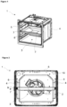
- the cooking device (1) comprises a tray (2) which is suitable for placing the ingredients to be cooked therein, a cooking chamber (3) wherein the tray (2) is placed, a casing (5) which surrounds the cooking chamber (3), which has two side walls (4) and which is in the form of a box with the front side being open, and at least one support (6) which is provided on the side wall (4) and which enables the tray (2) to be placed into the cooking chamber (3).
- the tray (2) is placed on the support (6).
- the support (6) can be in the form of a wire shelf disposed on the side wall (4) or in the form of a recess or protrusion formed on the side wall (4), suitable for the placement of the tray (2) thereon.
- the cooking device (1) of the present invention comprises an elastic member (7) which is disposed on the support (6) and which changes length by being squeezed by the weight of the tray (2) upon placing the tray (2) on the support (6), at least one magnet (8) which is placed onto the support (6) so as to generate a magnetic field with the elastic member (7), and a magnetic sensor (9) which is disposed on the side wall (4) and which detects the changes in the magnetic field intensity generated between the elastic member (7) and the magnet (8).
- the elastic member (7) comprises a material suitable for generating a magnetic field together with the magnet (8).
- the elastic member (7) can be a traditional spring or a spring steel.
- the elastic member (7) can be produced from an elastic material such as silicone resistant to high temperatures.
- the magnet (8) is a magnet (8) resistant to high temperatures, and is placed onto the support (6) so as to be positioned in the cooking chamber (3).
- the magnetic sensor (9) is disposed on the side wall (4) so as to be positioned outside the cooking chamber (3).
- the magnetic sensor (9) is disposed on the surface of the side wall (4) facing the outside so as to detect the magnetic field generated between the magnet (8) and the elastic member (7) and to be aligned with the magnet (8) which is disposed on the part of the side wall (4) facing the inner volume of the cooking chamber (3).
- the length of the elastic member (7) changes depending on the weight of the tray (2).
- the intensity of the magnetic field generated between the elastic member (7) and the magnet (8) also changes. Said change in the intensity of the magnetic field is detected by the magnetic sensor (9).
- the magnetic sensor (9) can determine the change in the length of the elastic member (7) depending on the change in the intensity of the magnetic field. Since the change in the length of the elastic member (7) is proportional to the weight of the tray (2), the weight of the ingredients in the tray (2) to be cooked can be determined.
- the cooking device (1) comprises a control unit (10) which processes the data received from the magnetic sensor (9) so as to perform the cooking program suitable for the weight of the tray (2).
- the control unit (10) regulates the operation of the cooking device (1). After the weight of the tray (2) placed into the cooking chamber (3) is determined by means of the data received from the magnetic sensor (9), the cooking program suitable for the determined weight is performed by the control unit (10).
- the control unit (10) determines the cooking time and the cooking method according to the weight of the foodstuff to be cooked. Thus, the efficiency of the cooking process is improved, providing savings in energy.
- the cooking device (1) comprises a plurality of magnets (8) which are disposed on the support (6).
- the intensity of the magnetic field generated between the magnets (8) and the elastic member (7) is also increased.
- the change in the length of the elastic member (7) causes the change in the intensity of the magnetic field to increase.
- the magnetic field is enabled to expand to the outside of the cooking chamber (3). Consequently, the detection of the change in the intensity of the magnetic field by the magnetic sensor (9) is facilitated.
- the cooking device (1) comprises two elastic members (7) each disposed on the support (6) on each of the two side walls (4), at least two magnets (8) with at least one being disposed on each of the supports (6), and two magnetic sensors (9) each disposed on each of the two side walls (4).
- One support (6) is provided on each of the two side walls (4).
- the tray (2) is placed onto the supports (6) in the cooking chamber (3).
- the weight of the tray (2) on the elastic member (7) is measured at the side of the two side walls (4).
- the cooking device (1) comprises a cut-out which is formed on the part of the side wall (4) aligned with the magnet (8).
- the magnet (8) is disposed on the support (6) provided on the part of the side wall (4) facing the inner volume of the cooking chamber (3), and a magnetic sensor (9) is disposed on the outer surface of the side wall (4).
- the intensity of the magnetic field generated between the magnet (8) and the elastic member (7) disposed on the support (6) decreases while passing through the side wall (4), and may get difficult to be detected by the magnetic sensor (9).
- a cut-out is formed on the part of the side wall (4) remaining between the magnet (8) and the magnetic sensor (9).
- the magnetic field generated in the cooking chamber (3) weakens less while passing through the side wall (4) and can be detected by the magnetic sensor (9) more easily.
- a material such as Teflon, silicone, etc. which is resistant to high temperatures and has a high magnetic permeability is filled into the formed cut-out.
- the cooking device (1) comprises the magnet (8) which is placed onto the support (6) so as to be positioned on the elastic member (7).
- a cooking device (1) is realized, wherein the weight of the tray (2) is efficiently detected by means of an elastic member (7) which changes in length depending on the weight of the tray (2) placed onto the support (6), a magnet (8), and a magnetic sensor (7) which is disposed on the side wall (4) so as to detect the changes in the magnetic field generated between the elastic member (7) and the magnet (8).
Landscapes
- Engineering & Computer Science (AREA)
- Chemical & Material Sciences (AREA)
- Combustion & Propulsion (AREA)
- Mechanical Engineering (AREA)
- General Engineering & Computer Science (AREA)
- Electric Ovens (AREA)
- Cookers (AREA)
Claims (5)
- Ein Kochgerät (1) umfasst eine Schale (2), die geeignet ist, die zu kochenden Zutaten darin zu platzieren, eine Garkammer (3), in der die Schale (2) platziert ist, ein Gehäuse (5), das die Garkammer (3) umgibt, das zwei Seitenwände (4) hat und das die Form eines Kastens hat, wobei die Vorderseite offen ist, und mindestens eine Stütze (6), die an der Seitenwand (4) vorgesehen ist und die es ermöglicht, die Schale (2) in die Garkammer (3) zu platzieren, gekennzeichnet ist es dadurch, dass- ein elastisches Element (7), das auf dem Träger (6) angeordnet ist und das seine Länge ändert, indem es durch das Gewicht des Tabletts (2) und der Bestandteile in dem Tablett (2) beim Aufsetzen des Tabletts (2) auf den Träger (6) zusammengedrückt wird, wobei die Abnahme der Länge des elastischen Elements proportional zu dem auf dem Träger (6) platzierten Gewicht ist oder eine bestimmte Korrelation mit diesem aufweist,- mindestens ein Magnet (8), der so auf der Unterlage (6) angeordnet ist, dass er mit dem elastischen Element (7) ein Magnetfeld erzeugt, und- ein Magnetsensor (9), der an der Seitenwand (4) angeordnet ist, die Änderungen der zwischen dem elastischen Element (7) und dem Magneten (8) erzeugten Magnetfeldstärke erfassen und die Längenänderung des elastischen Elements (7) auf der Grundlage der Änderung der Magnetfeldstärke bestimmen kann,- eine Steuereinheit (10), die die von dem Magnetsensor (9) empfangenen Daten verarbeitet, um das für das Gewicht des Tabletts (2) geeignete Garprogramm durchzuführen, wobei zwei elastische Elemente (7), die jeweils auf dem Träger (6) an jeder der beiden Seitenwände (4) angeordnet sind, mindestens zwei Magnete (8), von denen mindestens einer an jedem der Träger (6) angeordnet ist, und zwei Magnetsensoren (9), die jeweils an jeder der beiden Seitenwände (4) angeordnet sind.
- Ein Kochgerät (1), wie in Anspruch 1 aufgeführt, ist dadurch gekennzeichnet, dass eine Vielzahl von Magneten (8) auf dem Träger (6) angeordnet sind.
- Ein Kochgerät (1), wie in einem der vorherigen Ansprüchen aufgeführt, ist dadurch gekennzeichnet, dass eine Aussparung, die auf dem mit dem Magneten (8) ausgerichteten Teil der Seitenwand (4) ausgebildet ist.
- Ein Kochgerät (1), wie in einem der vorherigen Ansprüchen aufgeführt, ist dadurch gekennzeichnet, dass der Magnet (8), der auf dem Träger (6) angebracht ist, auf dem elastischen Element (7) positioniert wird.
- Ein Kochgerät (1), wie in einem der vorherigen Ansprüchen aufgeführt, ist dadurch gekennzeichnet, dass der Magnetsensor (9) an der Außenfläche der Seitenwand (4) angeordnet ist.
Applications Claiming Priority (1)
| Application Number | Priority Date | Filing Date | Title |
|---|---|---|---|
| TR2020/00745A TR202000745A1 (tr) | 2020-01-17 | 2020-01-17 | Yük mi̇ktari algilanan bi̇r pi̇şi̇ri̇ci̇ ci̇haz |
Publications (2)
| Publication Number | Publication Date |
|---|---|
| EP3851746A1 EP3851746A1 (de) | 2021-07-21 |
| EP3851746B1 true EP3851746B1 (de) | 2024-12-04 |
Family
ID=74186487
Family Applications (1)
| Application Number | Title | Priority Date | Filing Date |
|---|---|---|---|
| EP21151828.7A Active EP3851746B1 (de) | 2020-01-17 | 2021-01-15 | Gargerät zum erfassen der lastmenge |
Country Status (2)
| Country | Link |
|---|---|
| EP (1) | EP3851746B1 (de) |
| TR (1) | TR202000745A1 (de) |
Families Citing this family (1)
| Publication number | Priority date | Publication date | Assignee | Title |
|---|---|---|---|---|
| US12504175B2 (en) * | 2022-12-08 | 2025-12-23 | Whirlpool Corporation | Air-tight removable divider and thermal break |
Citations (1)
| Publication number | Priority date | Publication date | Assignee | Title |
|---|---|---|---|---|
| EP0173855B1 (de) * | 1984-07-30 | 1988-11-09 | Matsushita Electric Industrial Co., Ltd. | Heizapparat mit Detektor |
Family Cites Families (3)
| Publication number | Priority date | Publication date | Assignee | Title |
|---|---|---|---|---|
| KR970005758B1 (ko) | 1994-02-28 | 1997-04-19 | 엘지전자 주식회사 | 전자총의 전극간격 자동 측정장치 |
| KR20080037886A (ko) * | 2006-10-27 | 2008-05-02 | 삼성전자주식회사 | 열량정보 표시기능을 구비한 조리기기 및 열량정보표시방법 |
| DE102011010239B4 (de) * | 2011-02-03 | 2021-01-28 | Rational Aktiengesellschaft | Gargerät mit Einschuberkennung sowie Verfahren zur Einschuberkennung |
-
2020
- 2020-01-17 TR TR2020/00745A patent/TR202000745A1/tr unknown
-
2021
- 2021-01-15 EP EP21151828.7A patent/EP3851746B1/de active Active
Patent Citations (1)
| Publication number | Priority date | Publication date | Assignee | Title |
|---|---|---|---|---|
| EP0173855B1 (de) * | 1984-07-30 | 1988-11-09 | Matsushita Electric Industrial Co., Ltd. | Heizapparat mit Detektor |
Also Published As
| Publication number | Publication date |
|---|---|
| EP3851746A1 (de) | 2021-07-21 |
| TR202000745A1 (tr) | 2021-07-26 |
Similar Documents
| Publication | Publication Date | Title |
|---|---|---|
| EP2999301B1 (de) | Induktionskochfeld mit Siededetektion und Induktionsenergiesteuerung, Verfahren zum Erwärmen von Speisen mit einem Induktionskochfeld und Computerprogrammprodukt | |
| JP5043833B2 (ja) | 誘導加熱調理器、誘導加熱調理方法、誘導加熱調理プログラム、共振音検知装置、共振音検知方法及び共振音検知プログラム | |
| US6462316B1 (en) | Cooktop control and monitoring system including detecting properties of a utensil and its contents | |
| KR890006098A (ko) | 히터 에너지 계수기를 사용한 온도 감지 고장 검출 장치 | |
| EP3851746B1 (de) | Gargerät zum erfassen der lastmenge | |
| KR101345742B1 (ko) | 로드셀이 장착된 인덕션 레인지 | |
| WO2003014455A3 (de) | Wäschebehandlungsgerät mit unwuchtüberwachung, mit erkennung des niveaus oder mit erkennung der beladung | |
| CN107143893B (zh) | 一种电磁炉炊具的控制方法及其电磁炉炊具 | |
| EP1271061A2 (de) | Garofen mit Regeleinrichtung für eine Kerntemperaturprobe | |
| KR102120746B1 (ko) | 코팅면을 갖는 인덕션 레인지 | |
| CN111110018B (zh) | 烹饪器具和用于烹饪器具的压力控制方法 | |
| JP4206957B2 (ja) | 炊飯器 | |
| EP4127619B1 (de) | Sensormittel oder modul zur bestimmung einer verschiebung, durchbiegung oder biegung, haushaltsgerät und verfahren zur bestimmung des gewichts eines gegenstandes | |
| JP2005118318A (ja) | 炊飯器 | |
| US20250126685A1 (en) | Audible feedback system to guide pot centering on a cooktop | |
| KR960034872A (ko) | 가열조리기 | |
| EP4473884A1 (de) | Erfassung physikalischer parameter | |
| JP5887516B2 (ja) | 誘導加熱調理器 | |
| KR100204228B1 (ko) | 전자레인지의 조리제어시 커버유무 및 분량인식 방법 | |
| CN111122640A (zh) | 一种沸腾状态检测方法及应用该方法的烹饪系统 | |
| KR20040097856A (ko) | 전자레인지의 제어방법 | |
| KR100204227B1 (ko) | 전자레인지의 조리제어시 커버유무 및 분량인식 방법 | |
| KR100535686B1 (ko) | 압력 검출 장치 | |
| KR20230161858A (ko) | 유도 가열 장치 및 그 제어 방법 | |
| JP4134971B2 (ja) | 誘導加熱調理器 |
Legal Events
| Date | Code | Title | Description |
|---|---|---|---|
| PUAI | Public reference made under article 153(3) epc to a published international application that has entered the european phase |
Free format text: ORIGINAL CODE: 0009012 |
|
| STAA | Information on the status of an ep patent application or granted ep patent |
Free format text: STATUS: REQUEST FOR EXAMINATION WAS MADE |
|
| 17P | Request for examination filed |
Effective date: 20210115 |
|
| AK | Designated contracting states |
Kind code of ref document: A1 Designated state(s): AL AT BE BG CH CY CZ DE DK EE ES FI FR GB GR HR HU IE IS IT LI LT LU LV MC MK MT NL NO PL PT RO RS SE SI SK SM TR |
|
| STAA | Information on the status of an ep patent application or granted ep patent |
Free format text: STATUS: EXAMINATION IS IN PROGRESS |
|
| 17Q | First examination report despatched |
Effective date: 20240205 |
|
| GRAP | Despatch of communication of intention to grant a patent |
Free format text: ORIGINAL CODE: EPIDOSNIGR1 |
|
| STAA | Information on the status of an ep patent application or granted ep patent |
Free format text: STATUS: GRANT OF PATENT IS INTENDED |
|
| INTG | Intention to grant announced |
Effective date: 20240704 |
|
| GRAS | Grant fee paid |
Free format text: ORIGINAL CODE: EPIDOSNIGR3 |
|
| GRAA | (expected) grant |
Free format text: ORIGINAL CODE: 0009210 |
|
| STAA | Information on the status of an ep patent application or granted ep patent |
Free format text: STATUS: THE PATENT HAS BEEN GRANTED |
|
| AK | Designated contracting states |
Kind code of ref document: B1 Designated state(s): AL AT BE BG CH CY CZ DE DK EE ES FI FR GB GR HR HU IE IS IT LI LT LU LV MC MK MT NL NO PL PT RO RS SE SI SK SM TR |
|
| REG | Reference to a national code |
Ref country code: CH Ref legal event code: EP |
|
| REG | Reference to a national code |
Ref country code: DE Ref legal event code: R096 Ref document number: 602021022670 Country of ref document: DE |
|
| REG | Reference to a national code |
Ref country code: IE Ref legal event code: FG4D |
|
| REG | Reference to a national code |
Ref country code: LT Ref legal event code: MG9D |
|
| REG | Reference to a national code |
Ref country code: NL Ref legal event code: MP Effective date: 20241204 |
|
| PG25 | Lapsed in a contracting state [announced via postgrant information from national office to epo] |
Ref country code: HR Free format text: LAPSE BECAUSE OF FAILURE TO SUBMIT A TRANSLATION OF THE DESCRIPTION OR TO PAY THE FEE WITHIN THE PRESCRIBED TIME-LIMIT Effective date: 20241204 |
|
| PG25 | Lapsed in a contracting state [announced via postgrant information from national office to epo] |
Ref country code: FI Free format text: LAPSE BECAUSE OF FAILURE TO SUBMIT A TRANSLATION OF THE DESCRIPTION OR TO PAY THE FEE WITHIN THE PRESCRIBED TIME-LIMIT Effective date: 20241204 |
|
| PG25 | Lapsed in a contracting state [announced via postgrant information from national office to epo] |
Ref country code: BG Free format text: LAPSE BECAUSE OF FAILURE TO SUBMIT A TRANSLATION OF THE DESCRIPTION OR TO PAY THE FEE WITHIN THE PRESCRIBED TIME-LIMIT Effective date: 20241204 |
|
| PG25 | Lapsed in a contracting state [announced via postgrant information from national office to epo] |
Ref country code: ES Free format text: LAPSE BECAUSE OF FAILURE TO SUBMIT A TRANSLATION OF THE DESCRIPTION OR TO PAY THE FEE WITHIN THE PRESCRIBED TIME-LIMIT Effective date: 20241204 |
|
| PG25 | Lapsed in a contracting state [announced via postgrant information from national office to epo] |
Ref country code: NO Free format text: LAPSE BECAUSE OF FAILURE TO SUBMIT A TRANSLATION OF THE DESCRIPTION OR TO PAY THE FEE WITHIN THE PRESCRIBED TIME-LIMIT Effective date: 20250304 |
|
| PG25 | Lapsed in a contracting state [announced via postgrant information from national office to epo] |
Ref country code: LV Free format text: LAPSE BECAUSE OF FAILURE TO SUBMIT A TRANSLATION OF THE DESCRIPTION OR TO PAY THE FEE WITHIN THE PRESCRIBED TIME-LIMIT Effective date: 20241204 Ref country code: GR Free format text: LAPSE BECAUSE OF FAILURE TO SUBMIT A TRANSLATION OF THE DESCRIPTION OR TO PAY THE FEE WITHIN THE PRESCRIBED TIME-LIMIT Effective date: 20250305 |
|
| PG25 | Lapsed in a contracting state [announced via postgrant information from national office to epo] |
Ref country code: RS Free format text: LAPSE BECAUSE OF FAILURE TO SUBMIT A TRANSLATION OF THE DESCRIPTION OR TO PAY THE FEE WITHIN THE PRESCRIBED TIME-LIMIT Effective date: 20250304 |
|
| PG25 | Lapsed in a contracting state [announced via postgrant information from national office to epo] |
Ref country code: NL Free format text: LAPSE BECAUSE OF FAILURE TO SUBMIT A TRANSLATION OF THE DESCRIPTION OR TO PAY THE FEE WITHIN THE PRESCRIBED TIME-LIMIT Effective date: 20241204 |
|
| REG | Reference to a national code |
Ref country code: AT Ref legal event code: MK05 Ref document number: 1748544 Country of ref document: AT Kind code of ref document: T Effective date: 20241204 |
|
| PG25 | Lapsed in a contracting state [announced via postgrant information from national office to epo] |
Ref country code: SM Free format text: LAPSE BECAUSE OF FAILURE TO SUBMIT A TRANSLATION OF THE DESCRIPTION OR TO PAY THE FEE WITHIN THE PRESCRIBED TIME-LIMIT Effective date: 20241204 |
|
| PG25 | Lapsed in a contracting state [announced via postgrant information from national office to epo] |
Ref country code: PL Free format text: LAPSE BECAUSE OF FAILURE TO SUBMIT A TRANSLATION OF THE DESCRIPTION OR TO PAY THE FEE WITHIN THE PRESCRIBED TIME-LIMIT Effective date: 20241204 |
|
| PG25 | Lapsed in a contracting state [announced via postgrant information from national office to epo] |
Ref country code: IS Free format text: LAPSE BECAUSE OF FAILURE TO SUBMIT A TRANSLATION OF THE DESCRIPTION OR TO PAY THE FEE WITHIN THE PRESCRIBED TIME-LIMIT Effective date: 20250404 |
|
| PG25 | Lapsed in a contracting state [announced via postgrant information from national office to epo] |
Ref country code: PT Free format text: LAPSE BECAUSE OF FAILURE TO SUBMIT A TRANSLATION OF THE DESCRIPTION OR TO PAY THE FEE WITHIN THE PRESCRIBED TIME-LIMIT Effective date: 20250404 |
|
| PG25 | Lapsed in a contracting state [announced via postgrant information from national office to epo] |
Ref country code: EE Free format text: LAPSE BECAUSE OF FAILURE TO SUBMIT A TRANSLATION OF THE DESCRIPTION OR TO PAY THE FEE WITHIN THE PRESCRIBED TIME-LIMIT Effective date: 20241204 |
|
| PG25 | Lapsed in a contracting state [announced via postgrant information from national office to epo] |
Ref country code: AT Free format text: LAPSE BECAUSE OF FAILURE TO SUBMIT A TRANSLATION OF THE DESCRIPTION OR TO PAY THE FEE WITHIN THE PRESCRIBED TIME-LIMIT Effective date: 20241204 Ref country code: RO Free format text: LAPSE BECAUSE OF FAILURE TO SUBMIT A TRANSLATION OF THE DESCRIPTION OR TO PAY THE FEE WITHIN THE PRESCRIBED TIME-LIMIT Effective date: 20241204 |
|
| PG25 | Lapsed in a contracting state [announced via postgrant information from national office to epo] |
Ref country code: SK Free format text: LAPSE BECAUSE OF FAILURE TO SUBMIT A TRANSLATION OF THE DESCRIPTION OR TO PAY THE FEE WITHIN THE PRESCRIBED TIME-LIMIT Effective date: 20241204 |
|
| PG25 | Lapsed in a contracting state [announced via postgrant information from national office to epo] |
Ref country code: CZ Free format text: LAPSE BECAUSE OF FAILURE TO SUBMIT A TRANSLATION OF THE DESCRIPTION OR TO PAY THE FEE WITHIN THE PRESCRIBED TIME-LIMIT Effective date: 20241204 |
|
| REG | Reference to a national code |
Ref country code: CH Ref legal event code: PL |
|
| REG | Reference to a national code |
Ref country code: DE Ref legal event code: R097 Ref document number: 602021022670 Country of ref document: DE |
|
| PG25 | Lapsed in a contracting state [announced via postgrant information from national office to epo] |
Ref country code: SE Free format text: LAPSE BECAUSE OF FAILURE TO SUBMIT A TRANSLATION OF THE DESCRIPTION OR TO PAY THE FEE WITHIN THE PRESCRIBED TIME-LIMIT Effective date: 20241204 |
|
| PG25 | Lapsed in a contracting state [announced via postgrant information from national office to epo] |
Ref country code: LU Free format text: LAPSE BECAUSE OF NON-PAYMENT OF DUE FEES Effective date: 20250115 Ref country code: MC Free format text: LAPSE BECAUSE OF FAILURE TO SUBMIT A TRANSLATION OF THE DESCRIPTION OR TO PAY THE FEE WITHIN THE PRESCRIBED TIME-LIMIT Effective date: 20241204 |
|
| PG25 | Lapsed in a contracting state [announced via postgrant information from national office to epo] |
Ref country code: DK Free format text: LAPSE BECAUSE OF FAILURE TO SUBMIT A TRANSLATION OF THE DESCRIPTION OR TO PAY THE FEE WITHIN THE PRESCRIBED TIME-LIMIT Effective date: 20241204 |
|
| PLBE | No opposition filed within time limit |
Free format text: ORIGINAL CODE: 0009261 |
|
| STAA | Information on the status of an ep patent application or granted ep patent |
Free format text: STATUS: NO OPPOSITION FILED WITHIN TIME LIMIT |
|
| PG25 | Lapsed in a contracting state [announced via postgrant information from national office to epo] |
Ref country code: BE Free format text: LAPSE BECAUSE OF NON-PAYMENT OF DUE FEES Effective date: 20250131 |
|
| PG25 | Lapsed in a contracting state [announced via postgrant information from national office to epo] |
Ref country code: CH Free format text: LAPSE BECAUSE OF NON-PAYMENT OF DUE FEES Effective date: 20250131 |
|
| REG | Reference to a national code |
Ref country code: BE Ref legal event code: MM Effective date: 20250131 |
|
| 26N | No opposition filed |
Effective date: 20250905 |
|
| PG25 | Lapsed in a contracting state [announced via postgrant information from national office to epo] |
Ref country code: FR Free format text: LAPSE BECAUSE OF NON-PAYMENT OF DUE FEES Effective date: 20250204 |
|
| PG25 | Lapsed in a contracting state [announced via postgrant information from national office to epo] |
Ref country code: IE Free format text: LAPSE BECAUSE OF NON-PAYMENT OF DUE FEES Effective date: 20250115 |
|
| PGFP | Annual fee paid to national office [announced via postgrant information from national office to epo] |
Ref country code: GB Payment date: 20260123 Year of fee payment: 6 |
|
| PGFP | Annual fee paid to national office [announced via postgrant information from national office to epo] |
Ref country code: DE Payment date: 20260121 Year of fee payment: 6 |
|
| PGFP | Annual fee paid to national office [announced via postgrant information from national office to epo] |
Ref country code: IT Payment date: 20260126 Year of fee payment: 6 |
|
| PGFP | Annual fee paid to national office [announced via postgrant information from national office to epo] |
Ref country code: TR Payment date: 20260102 Year of fee payment: 6 |