EP3851407A2 - Beweglicher körper, station, bewegungssystem, bewegungsverfahren und programm - Google Patents
Beweglicher körper, station, bewegungssystem, bewegungsverfahren und programm Download PDFInfo
- Publication number
- EP3851407A2 EP3851407A2 EP20217017.1A EP20217017A EP3851407A2 EP 3851407 A2 EP3851407 A2 EP 3851407A2 EP 20217017 A EP20217017 A EP 20217017A EP 3851407 A2 EP3851407 A2 EP 3851407A2
- Authority
- EP
- European Patent Office
- Prior art keywords
- moving
- expansion
- engagement
- moving body
- control unit
- Prior art date
- Legal status (The legal status is an assumption and is not a legal conclusion. Google has not performed a legal analysis and makes no representation as to the accuracy of the status listed.)
- Withdrawn
Links
Images













Classifications
-
- B—PERFORMING OPERATIONS; TRANSPORTING
- B25—HAND TOOLS; PORTABLE POWER-DRIVEN TOOLS; MANIPULATORS
- B25J—MANIPULATORS; CHAMBERS PROVIDED WITH MANIPULATION DEVICES
- B25J5/00—Manipulators mounted on wheels or on carriages
- B25J5/007—Manipulators mounted on wheels or on carriages mounted on wheels
-
- B—PERFORMING OPERATIONS; TRANSPORTING
- B66—HOISTING; LIFTING; HAULING
- B66F—HOISTING, LIFTING, HAULING OR PUSHING, NOT OTHERWISE PROVIDED FOR, e.g. DEVICES WHICH APPLY A LIFTING OR PUSHING FORCE DIRECTLY TO THE SURFACE OF A LOAD
- B66F9/00—Devices for lifting or lowering bulky or heavy goods for loading or unloading purposes
- B66F9/06—Devices for lifting or lowering bulky or heavy goods for loading or unloading purposes movable, with their loads, on wheels or the like, e.g. fork-lift trucks
- B66F9/063—Automatically guided
-
- B—PERFORMING OPERATIONS; TRANSPORTING
- B62—LAND VEHICLES FOR TRAVELLING OTHERWISE THAN ON RAILS
- B62D—MOTOR VEHICLES; TRAILERS
- B62D63/00—Motor vehicles or trailers not otherwise provided for
- B62D63/02—Motor vehicles
-
- H—ELECTRICITY
- H02—GENERATION; CONVERSION OR DISTRIBUTION OF ELECTRIC POWER
- H02N—ELECTRIC MACHINES NOT OTHERWISE PROVIDED FOR
- H02N2/00—Electric machines in general using piezoelectric effect, electrostriction or magnetostriction
- H02N2/10—Electric machines in general using piezoelectric effect, electrostriction or magnetostriction producing rotary motion, e.g. rotary motors
- H02N2/101—Electric machines in general using piezoelectric effect, electrostriction or magnetostriction producing rotary motion, e.g. rotary motors using intermittent driving, e.g. step motors
-
- B—PERFORMING OPERATIONS; TRANSPORTING
- B25—HAND TOOLS; PORTABLE POWER-DRIVEN TOOLS; MANIPULATORS
- B25J—MANIPULATORS; CHAMBERS PROVIDED WITH MANIPULATION DEVICES
- B25J18/00—Arms
- B25J18/02—Arms extensible
-
- B—PERFORMING OPERATIONS; TRANSPORTING
- B25—HAND TOOLS; PORTABLE POWER-DRIVEN TOOLS; MANIPULATORS
- B25J—MANIPULATORS; CHAMBERS PROVIDED WITH MANIPULATION DEVICES
- B25J9/00—Program-controlled manipulators
- B25J9/0009—Constructional details, e.g. manipulator supports, bases
-
- B—PERFORMING OPERATIONS; TRANSPORTING
- B25—HAND TOOLS; PORTABLE POWER-DRIVEN TOOLS; MANIPULATORS
- B25J—MANIPULATORS; CHAMBERS PROVIDED WITH MANIPULATION DEVICES
- B25J9/00—Program-controlled manipulators
- B25J9/10—Program-controlled manipulators characterised by positioning means for manipulator elements
- B25J9/104—Program-controlled manipulators characterised by positioning means for manipulator elements with cables, chains or ribbons
-
- B—PERFORMING OPERATIONS; TRANSPORTING
- B25—HAND TOOLS; PORTABLE POWER-DRIVEN TOOLS; MANIPULATORS
- B25J—MANIPULATORS; CHAMBERS PROVIDED WITH MANIPULATION DEVICES
- B25J9/00—Program-controlled manipulators
- B25J9/16—Program controls
- B25J9/1602—Program controls characterised by the control system, structure, architecture
-
- B—PERFORMING OPERATIONS; TRANSPORTING
- B25—HAND TOOLS; PORTABLE POWER-DRIVEN TOOLS; MANIPULATORS
- B25J—MANIPULATORS; CHAMBERS PROVIDED WITH MANIPULATION DEVICES
- B25J9/00—Program-controlled manipulators
- B25J9/16—Program controls
- B25J9/1656—Program controls characterised by programming, planning systems for manipulators
- B25J9/1669—Program controls characterised by programming, planning systems for manipulators characterised by special application, e.g. multi-arm co-operation, assembly, grasping
-
- B—PERFORMING OPERATIONS; TRANSPORTING
- B25—HAND TOOLS; PORTABLE POWER-DRIVEN TOOLS; MANIPULATORS
- B25J—MANIPULATORS; CHAMBERS PROVIDED WITH MANIPULATION DEVICES
- B25J9/00—Program-controlled manipulators
- B25J9/16—Program controls
- B25J9/1679—Program controls characterised by the tasks executed
-
- B—PERFORMING OPERATIONS; TRANSPORTING
- B62—LAND VEHICLES FOR TRAVELLING OTHERWISE THAN ON RAILS
- B62D—MOTOR VEHICLES; TRAILERS
- B62D63/00—Motor vehicles or trailers not otherwise provided for
- B62D63/02—Motor vehicles
- B62D63/04—Component parts or accessories
-
- B—PERFORMING OPERATIONS; TRANSPORTING
- B66—HOISTING; LIFTING; HAULING
- B66B—ELEVATORS; ESCALATORS OR MOVING WALKWAYS
- B66B1/00—Control systems of elevators in general
- B66B1/02—Control systems without regulation, i.e. without retroactive action
- B66B1/06—Control systems without regulation, i.e. without retroactive action electric
-
- B—PERFORMING OPERATIONS; TRANSPORTING
- B66—HOISTING; LIFTING; HAULING
- B66F—HOISTING, LIFTING, HAULING OR PUSHING, NOT OTHERWISE PROVIDED FOR, e.g. DEVICES WHICH APPLY A LIFTING OR PUSHING FORCE DIRECTLY TO THE SURFACE OF A LOAD
- B66F13/00—Common constructional features or accessories
- B66F13/005—Thrust chain devices
-
- B—PERFORMING OPERATIONS; TRANSPORTING
- B66—HOISTING; LIFTING; HAULING
- B66F—HOISTING, LIFTING, HAULING OR PUSHING, NOT OTHERWISE PROVIDED FOR, e.g. DEVICES WHICH APPLY A LIFTING OR PUSHING FORCE DIRECTLY TO THE SURFACE OF A LOAD
- B66F3/00—Devices, e.g. jacks, adapted for uninterrupted lifting of loads
- B66F3/08—Devices, e.g. jacks, adapted for uninterrupted lifting of loads screw operated
-
- H—ELECTRICITY
- H02—GENERATION; CONVERSION OR DISTRIBUTION OF ELECTRIC POWER
- H02N—ELECTRIC MACHINES NOT OTHERWISE PROVIDED FOR
- H02N2/00—Electric machines in general using piezoelectric effect, electrostriction or magnetostriction
- H02N2/02—Electric machines in general using piezoelectric effect, electrostriction or magnetostriction producing linear motion, e.g. actuators; Linear positioners ; Linear motors
- H02N2/021—Electric machines in general using piezoelectric effect, electrostriction or magnetostriction producing linear motion, e.g. actuators; Linear positioners ; Linear motors using intermittent driving, e.g. step motors, piezoleg motors
- H02N2/025—Inertial sliding motors
-
- B—PERFORMING OPERATIONS; TRANSPORTING
- B65—CONVEYING; PACKING; STORING; HANDLING THIN OR FILAMENTARY MATERIAL
- B65G—TRANSPORT OR STORAGE DEVICES, e.g. CONVEYORS FOR LOADING OR TIPPING, SHOP CONVEYOR SYSTEMS OR PNEUMATIC TUBE CONVEYORS
- B65G1/00—Storing articles, individually or in orderly arrangement, in warehouses or magazines
- B65G1/02—Storage devices
- B65G1/04—Storage devices mechanical
- B65G1/0492—Storage devices mechanical with cars adapted to travel in storage aisles
Definitions
- the present disclosure relates to a moving body, a station, a movement system, and a moving method.
- a moving body equipped with a grasping mechanism for grasping a vertical member that vertically extends and connects level surfaces located at different heights, such as a lifting/lowering pole, is known (see, e.g., United States Patent No. 9,952,589 ).
- the moving body moves up and down along the lifting/lowering pole by vertically driving the grasping mechanism, and thereby moves between different level surfaces.
- the above-described moving body can move only between level surfaces that are connected by a vertical member. Therefore, there is a restriction that the moving body cannot move to a detached level surface that is not connected by the vertical member.
- the present disclosure has been made in order to solve the above-described problem and one of its main objects is to provide a moving body capable of freely moving between level surfaces located at different heights that are not connected by a vertical member, and provides a station, a movement system, and a moving method capable of freely moving such a moving body between such level surfaces.
- a first exemplary aspect is a moving body including:
- the moving body may further include a fixing part configured to fix the moving part when the expansion/contraction part is expanded or contracted.
- control unit when the control unit determines that the first engagement part has engaged with the member located at the target height position, the control unit may perform control so as to move the moving part to the target height position by expanding or contracting the expansion/contraction part.
- the expansion/contraction part may include a first belt including a first engagement mechanism and a second belt including a second engagement mechanism capable of engaging with and being disengaged from the first engagement mechanism, and the expansion/contraction part may form a columnar structure by spirally winding the first and second engagement mechanisms of the first and second belts around one and the same axis in a mutually overlapping state.
- a station including:
- another exemplary aspect is a movement system including the station and the moving body configured to move up and down in the station.
- the movement system may further include an object detection unit configured to detect an object located at a predetermined position below the through hole, and the control unit may move the moving part to the predetermined position and expand the expansion/contraction part when the object detection unit does not detect any object.
- an object detection unit configured to detect an object located at a predetermined position below the through hole
- the control unit may move the moving part to the predetermined position and expand the expansion/contraction part when the object detection unit does not detect any object.
- control unit may perform control so as to expand or contract the expansion/contraction part, to thereby engage the first engagement part with the second engagement part located at the target height position.
- control unit may perform control so as to, after engaging the first engagement part with the second engagement part, move the moving part to the target height position through the through hole by expanding or contracting the expansion/contraction part, close the opening/closing floor, and lower the moving part onto the opening/closing floor.
- another exemplary aspect may be a method for moving a moving body, the moving body including:
- a moving body capable of freely moving between level surfaces located at different heights that are not connected by a vertical member, and provides a station, a movement system, and a moving method capable of freely moving such a moving body between such level surfaces.
- Fig. 1 is a perspective view showing a schematic configuration of a moving body according to this embodiment.
- Fig. 2 is a side view showing a schematic configuration of the mobile body according to this embodiment.
- Fig. 3 is a block diagram showing a schematic system configuration of the mobile body according to this embodiment.
- a moving body 1 according to this embodiment can move between floor surfaces located at different heights in a moving environment such as a house, a facility, a warehouse, and a factory.
- the moving body 1 according to this embodiment includes a movable moving part 2, an expansion/contraction part 3 that expands and contracts in the vertical direction, a first engagement part 4 that engages with a member located in a surrounding environment, and a control unit 5 that controls the moving part 2 and the expansion/contraction part 3.
- the moving part 2 includes a moving body main body 21, a pair of left and right driving wheels 22 and a pair of front and rear driven wheels 23, all of which are rotatably mounted in the moving body main body 21, and a pair of motors 24 that rotationally drive the respective driving wheels 22.
- Each of the motors 24 rotates a respective one of the driving wheels 22 through a speed reducer or the like.
- Each of the motors 24 can rotate a respective one of the driving wheels 22 according to a control signal provided from the control unit 5, so that the moving body main body 21 can be moved to an arbitrary position.
- the above-described configuration of the moving part 2 is merely an example and is not limited to this example.
- the number of the driving wheels 22 of the moving part 2 and that of the driven wheels 23 thereof may be arbitrarily determined. That is, any configuration may be applied as long as the moving body main body 21 can be moved to an arbitrary position.
- the expansion/contraction part 3 may be configured as a telescopic type expanding/contracting mechanism that expands and contracts in the vertical direction.
- Fig. 4 shows an example of a columnar structure of the expansion/contraction part 3 (which will be described later).
- the expansion/contraction part 3 includes a first belt 32 including a first engagement mechanism 31, a second belt 34 including a second engagement mechanism 33 capable of engaging with and being disengaged from the first engagement mechanism 31, and a rotation apparatus 36 that rotates a columnar structure 35.
- the first and second belts 34 are made of a rigid material such as a metal plate or a hard synthetic resin plate, and have appropriate flexibility and elasticity.
- the expansion/contraction part 3 forms the columnar structure 35 by spirally winding the first and second engagement mechanisms 31 and 33 of the first and second belts 32 and 34 around one and the same axis in a mutually overlapping state.
- the first belt 32 is wound on the outer side of the second belt 34.
- a part on the upper-edge side of the first belt 32 overlaps (i.e., is placed over) a part on the lower-edge side of the second belt 34 that is disposed vertically above the first belt 32 from the outer side thereof, and a part on the upper-edge side of this second belt 34 overlaps (i.e., is placed under) a part on the lower-edge side of the first belt 32 that is disposed vertically above the second belt 34 from the inner side thereof. That is, the first and second belts 32 and 34, each of which is spirally wound, partially overlap each other in the axial direction in an alternative manner so that the columnar structure 35 is formed.
- the first and second engagement mechanisms 31 and 33 of the first and second belts 32 and 34 overlap each other.
- the first and second engagement mechanisms 31 and 33 are formed by, for example, an engagement pin and an engagement hole, and engage with each other. Since the overlapped parts of the surfaces of the first and second belts 32 and 34 are fixed to each other by the engagement of the first and second engagement mechanisms 31 and 33, the columnar structure 35 has high rigidity close to that of an integrally-formed columnar member.
- the rotation apparatus 36 includes a rotating mechanism for rotating the columnar structure 35 about the axis, a motor that drives the rotating mechanism, and so on.
- the rotation apparatus 36 By rotating the columnar structure 35, the rotation apparatus 36 winds up the housed first and second belts 32 and 34 along grooves or the like formed in a guide part 37, and spirally winds the first and second belts 32 and 34 around one and the same axis in a mutually overlapping state. By this spiral winding, the columnar structure 35 can be expanded in the axial direction. As described above, by winding the first and second belts 32 and 34, the columnar structure 35 can be expanded in the axial direction while maintaining high rigidity thereof.
- the rotation apparatus 36 rewinds the first and second belts 32 and 34 along grooves or the like formed in the guide part 37 and thereby separates them from the columnar structure 35, so that the columnar structure 35 can be contracted in the axial direction.
- the columnar structure 35 can be contracted (i.e., can be shorten) in the axial direction while housing the first and second belts 32 and 34 in a small space.
- the first engagement part 4 is disposed at the tip of the columnar structure 35 of the expansion/contraction part 3.
- the first engagement part 4 includes an engaging mechanism for engaging with a member located in the surrounding environment.
- the engaging mechanism is composed of, for example, a disk-shaped plate member 4 and functions as a hooking mechanism for being hooked on a level surface located at a different height.
- a flat placement part 41 on which an object such as baggage can be placed is provided on the top surface of the disk-shaped plate 4.
- the moving body 1 can transport an object placed on this placement part 41.
- the first engagement part 4 may be, for example, a sucking mechanism for sticking to a level surface located at a different height or a magnetically-sticking mechanism for magnetically sticking to a level surface located at a different height, or may be other arbitrary engaging mechanisms as long as they can engage with a member located in the surrounding environment.
- the control unit 5 controls the moving part 2 and the expansion/contraction part 3.
- the control unit 5 can control the rotation of each of the driving wheels 22 by transmitting a control signal to a respective one of the motors 24 of the moving part 2, and thereby can move the moving body main body 21 to an arbitrary position.
- the control unit 5 can expand and contract the columnar structure 35 in the axial direction by transmitting a control signal to the rotation apparatus 36 of the expansion/contraction part 3, and thereby can control the height position (i.e., the vertical position) of the first engagement part 4.
- the control unit 5 may control the movement of the moving body 1 by performing well-known control such as feedback control and robust control based on information about the rotations of the driving wheels 22 detected by a rotation sensor(s) provided in the driving wheels 22.
- the control unit 5 may autonomously move the moving body 1 by controlling the moving part 2 and the expansion/contraction part 3 based on information such as distance information detected by a range sensor such as a camera or an ultrasonic sensor provided in the moving body 1 and map information of the moving environment.
- control unit 5 may be formed by hardware mainly using a microcomputer including a CPU (Central Processing Unit) 51 that performs control processing, arithmetic processing, and so on, a memory 52 including a ROM (Read Only Memory) and/or a RAM (Random Access Memory) that stores a control program, an arithmetic program, and so on to be executed by the CPU 51, and an interface unit (I/F) 53 that externally receives and outputs signals.
- the CPU 51, the memory 52, and the interface unit 53 are connected with each other through a data bus or the like.
- a conventional moving body can move only between level surfaces that are connected by, for example, a vertical member such as a lifting/lowering pole. Therefore, there is a restriction that the moving body cannot move to a detached level surface that is not connected by a vertical member.
- the moving body 1 moves the moving part 2 to a target height position by engaging the first engagement part 4 with a member located at the target height position and then expanding or contracting the expansion/contraction part 3.
- the moving body 1 can move itself to the target height position and lower itself onto a floor surface located at that height position, without using any vertical member, by engaging the first engagement part 4 with a member located at the target height position and then expanding or contracting the expansion/contraction part 3. Therefore, the moving body 1 can freely move between level surfaces located at different heights that are not connected by a vertical member.
- the moving body 1 may further include a fixing part 6 that fixes the moving part 2 when the expansion/contraction part 3 is expanded or contracted.
- a fixing part 6 that fixes the moving part 2 when the expansion/contraction part 3 is expanded or contracted.
- the movement of the moving part 2 can be stabilized during the period in which the expansion/contraction part 3 of the moving body 1 is being expanded or contracted.
- the moving part 2 may become unstable due to the weight of the object placed on the placement part 41 of the first engagement part 4.
- the moving part 2 can be stabilized by fixing the moving part 2 by the fixing part 6.
- the fixing part 6 may be a fixing bar or the like that extends to the outside of the moving part 2 and lands on (i.e., comes into contact with) a road surface when the expansion/contraction part 3 is expanded or contracted. Further, the fixing part 6 may be a braking mechanism for putting a brake(s) on the driving wheels 22 and the driven wheels 23, or may be a combination of the above-described fixing bar and the braking mechanism.
- control unit 5 When the control unit 5 has determined that the first engagement part 4 has engaged with a member located at the target height position, the control unit 5 may perform control so as to move the moving part 2 to the target height position by expanding or contracting the expansion/contraction part 3. In this way, the moving part 2 can be stably moved to the target height position in a state where the first engagement part 4 is reliably engaged with the member located at the target height position.
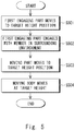
- Fig. 5 is a flowchart showing a flow of a moving method according to this embodiment.
- control unit 5 moves the first engagement part 4 to a target height position by controlling the expansion/contraction of the expansion/contraction part 3 (step S501).
- the control unit 5 engages the first engagement part 4 with a member located in the surrounding environment at the target height position (step S502).
- the control unit 5 moves the moving part 2 to the target height position and lowers it onto a floor surface located at that height position by controlling the expansion/contraction of the expansion/contraction part 3 (step S503).
- the control unit 5 contracts (i.e., shortens) the expansion/contraction part 3.
- the control unit 5 moves the moving body 1 on the floor surface located at the target height position by controlling the movement of the moving part 2 (step S504).
- the moving body 1 includes the movable moving part 2, the expansion/contraction part 3 disposed in the moving part 2 and configured to expand and contract in the vertical direction, the first engagement part 4 disposed at the tip of the expansion/contraction part 3 and configured to engage with a member located in the surrounding environment, and the control unit 5 configured to control the moving part 2 and the expansion/contraction part 3, in which the control unit 5 moves the moving part 2 to a target height position by engaging the first engagement part 4 with a member located at the target height position and then expanding or contracting the expansion/contraction part 3.
- the moving body 1 can move itself to the target height position and lower itself onto a floor surface located at that height position by engaging the first engagement part 4 with a member located at the target height position and then expanding or contracting the expansion/contraction part 3. Therefore, the moving body 1 can freely move between level surfaces located at different heights that are not connected by a vertical member.
- Fig. 6 is a block diagram showing a schematic system configuration of a movement system according to this embodiment.
- Fig. 7 shows a schematic configuration of a station according to this embodiment.
- the movement system 10 according to this embodiment includes a moving body 1 according to the above-described first embodiment and a station 11 in which the moving body 1 moves up and down.
- the station 11 is disposed in the moving environment of the moving body 1.
- the station 11 includes a second engagement part 12 that engages with the first engagement part 4 of the moving body 1, an engagement sliding part 13 that slides the second engagement part 12, an opening/closing floor 14 that slides on a floor surface, and a floor sliding part 15 that slides the opening/closing floor 14.
- the second engagement part 12 is formed in a fork-like shape.
- the second engagement part 12 is disposed so that it can slide in the horizontal direction in a place located above the opening/closing floor 14.
- the second engagement part 12 slides in the horizontal direction and is hooked (or caught) on the under surface of the disk-shaped first engagement part 4 of the moving body 1, so that the second engagement part 12 engages with the first engagement part 4.
- the control unit 5 of the moving body 1 can wirelessly communicate with the engagement sliding part 13 and the floor sliding part 15 by using, for example, a wireless LAN (Local Area Network).
- a wireless LAN Local Area Network
- the engagement sliding part 13 includes a sliding mechanism for horizontally sliding the second engagement part 12 at a predetermined height from the floor surface, a motor that drives the sliding mechanism, and so on.
- the engagement sliding part 13 slides the second engagement part 12 according to a control signal transmitted from the control unit 5 of the moving body 1.
- the engagement sliding part 13 engages the second engagement part 12 with the first engagement part 4 by sliding the second engagement part 12 in response to an engagement signal transmitted from the control unit 5 of the moving body 1.
- the engagement sliding part 13 disengages the second engagement part 12 from the first engagement part 4 by sliding the second engagement part 12 in response to a disengagement signal transmitted from the control unit 5 of the moving body 1.
- the opening/closing floor 14 horizontally slides above a through hole formed in the floor surface.
- the through hole in the floor surface is formed in such a size that the moving body 1 can vertically pass therethrough.
- the opening/closing floor 14 is formed in such a size that it can close the through hole when it is positioned over the through hole.
- the moving part 2 can get on the opening/closing floor 14 and travel thereon.
- the opening/closing floor 14 is in the closed state.
- the moving body 1 can vertically pass through the through hole.
- the floor sliding part 15 includes a sliding mechanism for horizontally sliding the opening/closing floor 14, a motor that drives the sliding mechanism, and so on.
- the floor sliding part 15 slides the opening/closing floor 14 according to a control signal transmitted from the control unit 5 of the moving body 1.
- the floor sliding part 15 slides the opening/closing floor 14 in response to a closing signal transmitted from the control unit 5 of the moving body 1 and thereby closes the through hole in the floor surface.
- the floor sliding part 15 slides the opening/closing floor 14 in response to an opening signal transmitted from the control unit 5 of the moving body 1 and thereby opens the through hole in the floor surface.
- the control unit 5 of the moving body 1 moves the moving body 1 to a predetermined position directly below the through hole in the second-floor surface by controlling the moving part 2 ( Fig. 8 ).
- control unit 5 can move the moving body 1 to the predetermined position based on image information acquired by the moving body 1 or a camera provided in the moving environment. Further, the control unit 5 may move the moving body 1 to the predetermined position when it has determined that there is no object such as an obstacle in the predetermined position based on image information acquired by a camera or information obtained by an ultrasonic sensor. In this way, it is possible, after it is confirmed that there is no obstructive object in the predetermined position, to reliably move the moving body 1 to the predetermined position and move it up or down.
- the camera and the ultrasonic sensor are specific examples of the object detection unit.
- control unit 5 of the moving body 1 determines that the moving part 2 has moved to the predetermined position directly below the through hole, it transmits an opening signal to the floor sliding part 15 of the station 11.
- the floor sliding part 15 slides the opening/closing floor 14 in response to the opening signal sent from the control unit 5 and thereby opens the through hole in the floor surface ( Fig. 9 ).
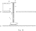
- control unit 5 When the control unit 5 has determined that the through hole in the floor surface has become the opened state, it moves the first engagement part 4 to the height position of the second engagement part 12 of the second-floor surface, i.e., to the target height position by expanding the expansion/contraction part 3 ( Fig. 10 ). Note that the control unit 5 may determine the opened/closed state of the opening/closing floor 14 based on image information acquired by the moving body 1 or a camera provided in the moving environment. The control unit 5 may determine the opened/closed state of the opening/closing floor 14 based on information obtained by a sensor provided in the opening/closing floor 14.
- control unit 5 When the control unit 5 has determined that the first engagement part 4 has moved to the height position of the second engagement part 12 of the second-floor surface, it transmits an engagement signal to the engagement sliding part 13.
- the engagement sliding part 13 slides the second engagement part 12 in response to the engagement signal transmitted from the control unit 5 and thereby engages it with the first engagement part 4 ( Fig. 11 ).
- the control unit 5 may determine that the first engagement part 4 has moved to the height position of the second engagement part 12 of the second-floor surface based on image information acquired by the moving body 1 or a camera provided in the moving environment.
- the control unit 5 may determine that the first engagement part 4 has moved to the height position of the second engagement part 12 of the second-floor surface based on information obtained by a sensor provided in the expansion/contraction part 3 or the like.
- control unit 5 When the control unit 5 has determined that the second engagement part 12 has engaged with the first engagement part 4, it pulls up (i.e., lifts) the moving part 2 to a position that is higher than the second-floor surface, i.e., the target position by a predetermined length by contracting (i.e., shortening) the expansion/contraction part 3 ( Fig. 12 ).
- the above-described predetermined length is stored in a memory or the like in advance.
- a length because of which the opening/closing floor 14 does not come into contact with any component located in the underside of the moving part 2 (such as a wheel) when the opening/closing floor 14 is opened or closed is set.
- the control unit 5 may determine that the second engagement part 12 has engaged with the first engagement part 4 based on image information acquired by the moving body 1 or a camera provided in the moving environment.
- the control unit 5 may determine that the second engagement part 12 has engaged with the first engagement part 4 based on information obtained by a sensor disposed in the first engagement part 4 or the second engagement part 12, or the like.
- control unit 5 When the control unit 5 has determined that the moving part 2 has been pulled up (i.e., lifted) to the position higher than the second-floor surface, i.e., the target position by the predetermined length, it transmits a closing signal to the floor sliding part 15.
- the floor sliding part 15 slides the opening/closing floor 14 in response to the closing signal sent from the control unit 5 and thereby closes the through hole in the floor surface ( Fig. 13 ).
- the control unit 5 may determine that the moving part 2 has been pulled up (i.e., lifted) to the position higher than the second-floor surface by the predetermined length based on information (such as a contraction length) obtained by a sensor provided in the expansion/contraction part 3.
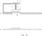
- control unit 5 When the control unit 5 has determined that the opening/closing floor 14 has become the closed state, it lowers the moving part 2 onto the opening/closing floor 14 by expanding the expansion/contraction part 3 ( Fig. 14 ).
- control unit 5 When the control unit 5 has determined that the moving part 2 has been placed on the opening/closing floor 14, it transmits a disengagement signal to the engagement sliding part 13. In response to the disengagement signal transmitted from the control unit 5, the engagement sliding part 13 slides the second engagement part 12 and thereby disengages it from the first engagement part 4 ( Fig. 15 ).
- the control unit 5 may determine that the moving part 2 has been lowered onto the opening/closing floor 14 based on information (such as a contraction length) obtained by a sensor provided in the expansion/contraction part 3.
- the control unit 5 contracts the expansion/contraction part 3 into its most contracted state (hereinafter simply referred to as a contracted state) ( Fig. 16 ).
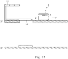
- control unit 5 When the control unit 5 has determined that the expansion/contraction part 3 has become the contracted state, it moves the moving body 1 to a desired position on the second floor by controlling the moving part 2 ( Fig. 17 ).
- the control unit 5 of the moving body 1 moves the moving body 1 to a position on the opening/closing floor 14 disposed on the second-floor surface by controlling the moving part 2 based on image information acquired by a camera or the like ( Fig. 18 ).
- the control unit 5 may move the moving body 1 to the position on the opening/closing floor 14 when it has determined that there is no object such as an obstacle on the opening/closing floor 14 based on image information acquired by a camera or information obtained by an ultrasonic sensor.
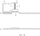
- control unit 5 When the control unit 5 has determined that the moving part 2 has moved to the position on the opening/closing floor 14, it moves the first engagement part 4 to the height position of the second engagement part 12 by expanding the expansion/contraction part 3 ( Fig. 19 ).
- control unit 5 When the control unit 5 has determined that the first engagement part 4 has moved to the height position of the second engagement part 12, it transmits an engagement signal to the engagement sliding part 13.
- the engagement sliding part 13 slides the second engagement part 12 in response to the engagement signal transmitted from the control unit 5 and thereby engages it with the first engagement part 4 ( Fig. 20 ).
- control unit 5 When the control unit 5 has determined that the second engagement part 12 has engaged with the first engagement part 4, it pulls up (i.e., lifts) the moving part 2 to a position that is higher than the second-floor surface by a predetermined length by contracting (i.e., shortening) the expansion/contraction part 3 ( Fig. 21 ).
- control unit 5 When the control unit 5 has determined that the moving part 2 has been pulled up (i.e., lifted) to the position higher than the second-floor surface by the predetermined length, it transmits an opening signal to the floor sliding part 15.
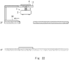
- the floor sliding part 15 slides the opening/closing floor 14 in response to the opening signal from the control unit 5 and thereby opens the through hole in the floor surface ( Fig. 22 ).
- control unit 5 When the control unit 5 has determined that the through hole in the floor surface has become the opened state, it lowers the moving part 2 onto a predetermined position on the first-floor surface, i.e., to the target position by expanding the expansion/contraction part 3 ( Fig. 23 ).
- control unit 5 When the control unit 5 has determined that the moving part 2 has been lowered onto the predetermined position on the first-floor surface, it transmits a disengagement signal to the engagement sliding part 13.
- the engagement sliding part 13 slides the second engagement part 12 in response to the disengagement signal transmitted from the control unit 5 and thereby disengages the second engagement part 12 from the first engagement part 4 ( Fig. 24 ).
- control unit 5 When the control unit 5 has determined that the first engagement part 4 has been disengaged from the second engagement part 12, it contracts (i.e., shortens) the expansion/contraction part 3 into the contracted state ( Fig. 25 ).
- control unit 5 When the control unit 5 has determined that the expansion/contraction part 3 has become the contracted state, it moves the moving body 1 to a desired position on the first floor by controlling the moving part 2 ( Fig. 26 ).
- a configuration in which a pair of the opening/closing floor 14 and the second engagement part 12 is provided in the second-floor surface is described.
- the present disclosure is not limited such a configuration.
- a configuration in which a plurality of pairs of opening/closing floors 14 and second engagement parts 12 may be provided in the second-floor surface may be adopted ( Fig. 27 ).
- the moving body 1 selects one of the plurality of pairs of opening/closing floors 14 and second engagement parts 12, and moves up or down by using the selected opening/closing floor 14 and the second engagement part 12 as described above.
- the moving body 1 is configured to move up and down between the first and second floors, but the present disclosure is not limited such a configuration.
- the moving body 1 may be configured to move up and down between the first floor and the third floor or a higher floor, or may be configured to move up and down between an arbitrary floor and another arbitrary floor.
- the through holes in all the floors are formed so that they are centered on one and the same axis.
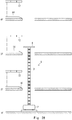
- an opening/closing floor 14 and a second engagement part 12 are provided for each of the through holes in all the floors ( Fig. 28 ).
- the control unit 5 of the moving body 1 can move to a target floor by operating the opening/closing floor 14 and the second engagement part 12 on the target floor in a manner similar to the above-described manner.
- control unit 5 moves the moving body 1 to a predetermined position directly below the through hole in the second-floor surface by controlling the moving part 2.
- control unit 5 of the moving body 1 When the control unit 5 of the moving body 1 has determined that the moving part 2 has moved to the predetermined position directly below the through hole, it transmits an opening signal to the floor sliding parts 15 on the second and third floors.
- the floor sliding parts 15 on the second and third floors slide the opening/closing floors 14 on the second and third floors in response to the opening signal sent from the control unit 5 and thereby open the through holes in the floor surfaces on the second and third floors.
- control unit 5 When the control unit 5 has determined that the through holes in the floor surfaces on the second and third floors have become the opened state, it moves the first engagement part 4 to the height position of the second engagement part 12 of the third-floor surface, i.e., to the target height position by expanding the expansion/contraction part 3.
- control unit 5 When the control unit 5 has determined that the first engagement part 4 has moved to the height position of the second engagement part 12 in the third-floor surface, it transmits an engagement signal to the engagement sliding part 13 on the third floor.
- the engagement sliding part 13 on the third floor slides the second engagement part 12 on the third floor in response to the engagement signal transmitted from the control unit 5 and thereby engages it with the first engagement part 4.
- control unit 5 When the control unit 5 has determined that the second engagement part 12 on the third floor has engaged with the first engagement part 4, it pulls up (i.e., lifts) the moving part 2 to a position that is higher than the third-floor surface, i.e., the target height position by a predetermined length by contracting (i.e., shortening) the expansion/contraction part 3.
- the control unit 5 When the control unit 5 has determined that the moving part 2 has been pulled up (i.e., lifted) to the position higher than the third-floor surface by the predetermined length, it transmits a closing signal to the floor sliding parts 15 on the second and third floors.
- the floor sliding parts 15 slide the opening/closing floors 14 on the second and third floors in response to the closing signal sent from the control unit 5 and thereby close the through holes in the floor surfaces on the second and third floors.
- control unit 5 When the control unit 5 has determined that the opening/closing floors 14 on the second and third floors have become the closed state, it lowers the moving part 2 onto the opening/closing floor 14 on the third floor by expanding the expansion/contraction part 3.
- control unit 5 When the control unit 5 has determined that the moving part 2 has been lowered onto the opening/closing floor 14 on the third floor, it transmits a disengagement signal to the engagement sliding part 13.
- the engagement sliding part 13 slides the second engagement part 12 on the third floor in response to the disengagement signal transmitted from the control unit 5 and thereby disengages it from the first engagement part 4.
- control unit 5 When the control unit 5 has determined that the first engagement part 4 has been disengaged from the second engagement part 12 on the third floor, it contracts (i.e., shortens) the expansion/contraction part 3 into the contracted state.
- control unit 5 When the control unit 5 has determined that the expansion/contraction part 3 has become the contracted state, it moves the moving body 1 to a desired position on the third floor by controlling the moving part 2.
- Fig. 5 can be implemented by having a CPU execute a computer program.
- Non-transitory computer readable media include any type of tangible storage media.
- Examples of non-transitory computer readable media include magnetic storage media (such as floppy disks, magnetic tapes, hard disk drives, etc.), optical magnetic storage media (e.g. magneto-optical disks), CD-ROM (compact disc read only memory), CD-R (compact disc recordable), CD-R/W (compact disc rewritable), and semiconductor memories (such as mask ROM, PROM (programmable ROM), EPROM (erasable PROM), flash ROM, RAM (random access memory), etc.).
- magnetic storage media such as floppy disks, magnetic tapes, hard disk drives, etc.
- optical magnetic storage media e.g. magneto-optical disks
- CD-ROM compact disc read only memory
- CD-R compact disc recordable
- CD-R/W compact disc rewritable
- semiconductor memories such as mask ROM, PROM (programmable ROM), EPROM (erasable PROM), flash ROM
- the program may be provided to a computer using any type of transitory computer readable media.
- Examples of transitory computer readable media include electric signals, optical signals, and electromagnetic waves.
- Transitory computer readable media can provide the program to a computer through a wired communication line (e.g. electric wires, and optical fibers) or a wireless communication line.
Landscapes
- Engineering & Computer Science (AREA)
- Mechanical Engineering (AREA)
- Robotics (AREA)
- Transportation (AREA)
- Structural Engineering (AREA)
- Automation & Control Theory (AREA)
- Life Sciences & Earth Sciences (AREA)
- Geology (AREA)
- Chemical & Material Sciences (AREA)
- Combustion & Propulsion (AREA)
- Civil Engineering (AREA)
- Manipulator (AREA)
- Control Of Position, Course, Altitude, Or Attitude Of Moving Bodies (AREA)
Applications Claiming Priority (1)
| Application Number | Priority Date | Filing Date | Title |
|---|---|---|---|
| JP2019231858A JP7327149B2 (ja) | 2019-12-23 | 2019-12-23 | 移動システム及びその移動方法 |
Publications (2)
| Publication Number | Publication Date |
|---|---|
| EP3851407A2 true EP3851407A2 (de) | 2021-07-21 |
| EP3851407A3 EP3851407A3 (de) | 2022-03-02 |
Family
ID=73857110
Family Applications (1)
| Application Number | Title | Priority Date | Filing Date |
|---|---|---|---|
| EP20217017.1A Withdrawn EP3851407A3 (de) | 2019-12-23 | 2020-12-23 | Beweglicher körper, station, bewegungssystem, bewegungsverfahren und programm |
Country Status (5)
| Country | Link |
|---|---|
| US (1) | US11509243B2 (de) |
| EP (1) | EP3851407A3 (de) |
| JP (1) | JP7327149B2 (de) |
| KR (1) | KR102421028B1 (de) |
| CN (1) | CN113086052B (de) |
Families Citing this family (8)
| Publication number | Priority date | Publication date | Assignee | Title |
|---|---|---|---|---|
| JP7552559B2 (ja) | 2021-11-15 | 2024-09-18 | トヨタ自動車株式会社 | 制御システム、制御方法、及びプログラム |
| JP7524882B2 (ja) | 2021-11-15 | 2024-07-30 | トヨタ自動車株式会社 | 制御システム、制御方法、及びプログラム |
| JP7632401B2 (ja) * | 2022-06-27 | 2025-02-19 | トヨタ自動車株式会社 | 伸展パイプおよび搬送ロボット |
| JP2024081904A (ja) * | 2022-12-07 | 2024-06-19 | トヨタ自動車株式会社 | 螺旋状進退作動装置、筒状伸縮体用帯材、及び筒状伸縮体用帯材の製造方法 |
| JP7816190B2 (ja) * | 2023-01-18 | 2026-02-18 | トヨタ自動車株式会社 | 伸縮装置 |
| JP7848724B2 (ja) * | 2023-02-27 | 2026-04-21 | トヨタ自動車株式会社 | 伸縮装置 |
| JP2024124784A (ja) * | 2023-03-03 | 2024-09-13 | トヨタ自動車株式会社 | 伸縮装置 |
| JP7827002B2 (ja) * | 2023-04-14 | 2026-03-10 | トヨタ自動車株式会社 | 螺旋状進退作動装置 |
Citations (2)
| Publication number | Priority date | Publication date | Assignee | Title |
|---|---|---|---|---|
| JP2007192257A (ja) | 2006-01-17 | 2007-08-02 | Namiki Denki Kogyosho:Kk | 螺旋状進退作動装置 |
| US9952589B1 (en) | 2017-03-30 | 2018-04-24 | Amazon Technologies, Inc. | Inventory system with swiveling vertically mobile drive units |
Family Cites Families (12)
| Publication number | Priority date | Publication date | Assignee | Title |
|---|---|---|---|---|
| JPS5521359A (en) * | 1978-07-31 | 1980-02-15 | Shin Meiwa Ind Co Ltd | Container transfer apparatus within building |
| JP2002285707A (ja) | 2001-03-26 | 2002-10-03 | Nittetsu Mining Co Ltd | 墜落防止装置 |
| US8721250B2 (en) * | 2012-07-11 | 2014-05-13 | Sergey N. Razumov | Robotic device movable in three mutually perpendicular directions |
| TWI594933B (zh) * | 2013-03-15 | 2017-08-11 | 辛波提克有限責任公司 | 自動化貯藏及取放系統 |
| US8721251B1 (en) * | 2013-04-01 | 2014-05-13 | Sergey N. Razumov | Self-lifting robotic device with movable carriages |
| US9920545B2 (en) | 2013-10-13 | 2018-03-20 | Maytronics Ltd. | Autonomous pool cleaning robot |
| JP6505442B2 (ja) * | 2015-01-14 | 2019-04-24 | サンナイス株式会社 | 無人車 |
| US10023434B2 (en) | 2016-09-19 | 2018-07-17 | Amazon Technologies, Inc. | Robotic enabled vertical lift |
| CN207523832U (zh) * | 2017-11-17 | 2018-06-22 | 西安优艾智合机器人科技有限公司 | 一种轮式自主移动机器人 |
| CN108000478B (zh) * | 2017-12-13 | 2023-08-08 | 北京极智嘉科技股份有限公司 | 柔性底座和搬运机器人 |
| CN208847255U (zh) * | 2018-10-31 | 2019-05-10 | 仲恺农业工程学院 | 设施蔬菜生长环境因子采集装置 |
| CN209650412U (zh) * | 2019-01-10 | 2019-11-19 | 先马智能科技(成都)有限公司 | 一种用于将料筒搬运至agv上的卡槽式机构 |
-
2019
- 2019-12-23 JP JP2019231858A patent/JP7327149B2/ja active Active
-
2020
- 2020-11-18 US US16/951,482 patent/US11509243B2/en active Active
- 2020-12-18 KR KR1020200178018A patent/KR102421028B1/ko active Active
- 2020-12-22 CN CN202011529106.2A patent/CN113086052B/zh active Active
- 2020-12-23 EP EP20217017.1A patent/EP3851407A3/de not_active Withdrawn
Patent Citations (2)
| Publication number | Priority date | Publication date | Assignee | Title |
|---|---|---|---|---|
| JP2007192257A (ja) | 2006-01-17 | 2007-08-02 | Namiki Denki Kogyosho:Kk | 螺旋状進退作動装置 |
| US9952589B1 (en) | 2017-03-30 | 2018-04-24 | Amazon Technologies, Inc. | Inventory system with swiveling vertically mobile drive units |
Also Published As
| Publication number | Publication date |
|---|---|
| JP7327149B2 (ja) | 2023-08-16 |
| KR20210081266A (ko) | 2021-07-01 |
| JP2021099724A (ja) | 2021-07-01 |
| EP3851407A3 (de) | 2022-03-02 |
| KR102421028B1 (ko) | 2022-07-14 |
| US11509243B2 (en) | 2022-11-22 |
| US20210194388A1 (en) | 2021-06-24 |
| CN113086052B (zh) | 2023-01-03 |
| CN113086052A (zh) | 2021-07-09 |
Similar Documents
| Publication | Publication Date | Title |
|---|---|---|
| US11509243B2 (en) | Moving body, station, movement system, moving method, and program | |
| EP3750839B1 (de) | Autonomer beweglicher körper, steuerungsprogramm eines autonomen beweglichen körpers, verfahren zur steuerung eines autonomen beweglichen körpers und systemserver zur steuerung eines autonomen beweglichen körpers von einem entfernten ort | |
| JP5784051B2 (ja) | エレベータシステム | |
| US8339086B2 (en) | System for syncronizing a plurality of roller shades using variable linear velocities | |
| CN114364859A (zh) | 具有智能卷边条的电动卷帘以及操作所述电动卷帘的方法 | |
| EP3449979A1 (de) | Artikelbeförderungseinrichtung | |
| US11851936B2 (en) | System and method for movable barrier monitoring | |
| US10472843B2 (en) | Vehicle vending machine | |
| JP2010134656A (ja) | 自律移動体および速度制御方法 | |
| US10519705B2 (en) | Intelligent safety door | |
| US20220258347A1 (en) | Transport system, moving method of operation target and storage medium | |
| JP7476819B2 (ja) | 搬送システム及び搬送方法 | |
| CN114852647A (zh) | 运输系统、运输方法和计算机可读记录介质 | |
| US20220234826A1 (en) | Opening-closing control device, opening-closing control system, task system, opening-closing control method, and computer-readable medium | |
| US10665101B2 (en) | Concept for controlling traffic inside a parking facility | |
| JP7613098B2 (ja) | タスクシステム | |
| JP2024154151A (ja) | 配送システム、配送方法、プログラム | |
| KR20240083199A (ko) | 자율주행로봇의 이동성을 확장하기 위한 장치, 방법 및 컴퓨터 판독가능 저장매체 | |
| US20210077328A1 (en) | Overhead subject lifts and methods for operating the same | |
| JP5671164B1 (ja) | 駐車装置 | |
| US11607813B2 (en) | Systems and methods for under-stair storage and retrieval | |
| KR102827110B1 (ko) | 자동문 끼임 감지 시스템 및 방법 | |
| JP2020070581A (ja) | 駐車装置 | |
| US20220227576A1 (en) | Trash box | |
| US20260010167A1 (en) | Parking Robot Safety Device and Method |
Legal Events
| Date | Code | Title | Description |
|---|---|---|---|
| PUAI | Public reference made under article 153(3) epc to a published international application that has entered the european phase |
Free format text: ORIGINAL CODE: 0009012 |
|
| STAA | Information on the status of an ep patent application or granted ep patent |
Free format text: STATUS: REQUEST FOR EXAMINATION WAS MADE |
|
| 17P | Request for examination filed |
Effective date: 20210109 |
|
| AK | Designated contracting states |
Kind code of ref document: A2 Designated state(s): AL AT BE BG CH CY CZ DE DK EE ES FI FR GB GR HR HU IE IS IT LI LT LU LV MC MK MT NL NO PL PT RO RS SE SI SK SM TR |
|
| PUAL | Search report despatched |
Free format text: ORIGINAL CODE: 0009013 |
|
| AK | Designated contracting states |
Kind code of ref document: A3 Designated state(s): AL AT BE BG CH CY CZ DE DK EE ES FI FR GB GR HR HU IE IS IT LI LT LU LV MC MK MT NL NO PL PT RO RS SE SI SK SM TR |
|
| RIC1 | Information provided on ipc code assigned before grant |
Ipc: B66F 13/00 20060101ALI20220127BHEP Ipc: B66F 3/08 20060101ALI20220127BHEP Ipc: B65G 1/04 20060101ALI20220127BHEP Ipc: B66F 9/06 20060101AFI20220127BHEP |
|
| STAA | Information on the status of an ep patent application or granted ep patent |
Free format text: STATUS: THE APPLICATION HAS BEEN WITHDRAWN |
|
| 18W | Application withdrawn |
Effective date: 20230706 |