EP3851355B1 - Portal axle for a bogie of a rail vehicle - Google Patents
Portal axle for a bogie of a rail vehicle Download PDFInfo
- Publication number
- EP3851355B1 EP3851355B1 EP20152390.9A EP20152390A EP3851355B1 EP 3851355 B1 EP3851355 B1 EP 3851355B1 EP 20152390 A EP20152390 A EP 20152390A EP 3851355 B1 EP3851355 B1 EP 3851355B1
- Authority
- EP
- European Patent Office
- Prior art keywords
- axle
- portal
- accordance
- bogie
- support
- Prior art date
- Legal status (The legal status is an assumption and is not a legal conclusion. Google has not performed a legal analysis and makes no representation as to the accuracy of the status listed.)
- Active
Links
- 229920001971 elastomer Polymers 0.000 claims description 8
- 239000000806 elastomer Substances 0.000 claims description 8
- 230000000712 assembly Effects 0.000 description 5
- 238000000429 assembly Methods 0.000 description 5
- 239000002184 metal Substances 0.000 description 3
- 238000007906 compression Methods 0.000 description 2
- 238000009434 installation Methods 0.000 description 2
- 239000007787 solid Substances 0.000 description 2
- 230000006835 compression Effects 0.000 description 1
- 230000001419 dependent effect Effects 0.000 description 1
- 230000005484 gravity Effects 0.000 description 1
Images


Classifications
-
- B—PERFORMING OPERATIONS; TRANSPORTING
- B61—RAILWAYS
- B61F—RAIL VEHICLE SUSPENSIONS, e.g. UNDERFRAMES, BOGIES OR ARRANGEMENTS OF WHEEL AXLES; RAIL VEHICLES FOR USE ON TRACKS OF DIFFERENT WIDTH; PREVENTING DERAILING OF RAIL VEHICLES; WHEEL GUARDS, OBSTRUCTION REMOVERS OR THE LIKE FOR RAIL VEHICLES
- B61F3/00—Types of bogies
- B61F3/16—Types of bogies with a separate axle for each wheel
-
- B—PERFORMING OPERATIONS; TRANSPORTING
- B61—RAILWAYS
- B61F—RAIL VEHICLE SUSPENSIONS, e.g. UNDERFRAMES, BOGIES OR ARRANGEMENTS OF WHEEL AXLES; RAIL VEHICLES FOR USE ON TRACKS OF DIFFERENT WIDTH; PREVENTING DERAILING OF RAIL VEHICLES; WHEEL GUARDS, OBSTRUCTION REMOVERS OR THE LIKE FOR RAIL VEHICLES
- B61F5/00—Constructional details of bogies; Connections between bogies and vehicle underframes; Arrangements or devices for adjusting or allowing self-adjustment of wheel axles or bogies when rounding curves
- B61F5/26—Mounting or securing axle-boxes in vehicle or bogie underframes
- B61F5/30—Axle-boxes mounted for movement under spring control in vehicle or bogie underframes
- B61F5/305—Axle-boxes mounted for movement under spring control in vehicle or bogie underframes incorporating rubber springs
Definitions
- the invention relates to the portal axle for a bogie of a rail vehicle, in particular a low-floor rail vehicle, with the features of the preamble of claim 1 and a bogie with such a portal axle.
- Portal axles of the type mentioned are well known from the prior art as parts of a bogie for a rail vehicle, in particular a low-floor rail vehicle.
- a portal axle of a bogie of a rail vehicle having a frame with support arms arranged at the ends of the frame.
- the support arm has a bridge which is pivotably arranged on the support arm, with primary spring assemblies being arranged on the inside of the bridge, which are fastened on the one hand to the bridge and on the other hand to the portal axle.
- the DE 2006 044 614 A1 discloses an axle with a swing arm solution in which the swing arms have gears that serve as wheel set bearings.
- the storage is thus designed as a so-called external storage, which is useful for rail vehicles that are operated on a so-called meter gauge. Steering knuckles with a respective axle shoulder are not disclosed, so that it can also be seen here that conventional solid axles only allow a small angle of rotation.
- one from the WO 2014/177417 A1 known bogie of a rail vehicle comprises a frame with a pivot bearing for the car body of the rail vehicle.
- Two portal axles are provided at a distance from one another on the frame, each of the portal axles having a spring arm at each of the two outwardly protruding ends.
- On the spring arm is a coil spring as the primary spring arranged on which the frame for receiving the pivot bearing is supported.
- the WO 2018/042326 A1 again shows a portal axle of a bogie, the portal axle having a steering knuckle at each end for receiving the wheel.
- the steering knuckle is approximately U-shaped with sloping flanks. Openings for receiving fastening means for fixing coil springs are provided in front of and behind the steering knuckle.
- a disadvantage of the design of the bogies with portal axles according to the three references mentioned above is that in the area of each wheel at least one, preferably two, vertically arranged primary springs are provided, on which the frame for accommodating the pivot bearing is supported, because the primary springs at least respective outer area of the rotary bearing limits the angle of rotation of the vehicle relative to the bogie.
- the DE 4 428 038 C1 also shows a bogie with a frame, the frame of the bogie having four individually suspended wheels to accommodate the pivot bearing for the car body.
- the wheels are each pivoted on the frame by a pivot arm.
- the frame is supported by frame supports on the swivel arm in the area of the wheel on a spring assembly, with the spring assembly sitting on the swivel arm at an angle.
- a portal axle in the true sense is not intended for this bogie.
- the object on which the invention is based is to provide a maximum angle of rotation while at the same time having a continuously level floor.
- the portal axle in order to support a frame of the bogie of the rail vehicle, on the one hand the portal axle has a swivel arm at both ends for the pivotable connection of the portal axle to the frame and on the other hand each of the two steering knuckles has a first axle shoulder with a spring device arranged thereon for resilient support of the frame on a support surface of the axle shoulder.
- the axle shoulder and the swivel arm are oriented to one another in such a way that a normal vector of the support surface and a longitudinal axis of the swivel arm enclose an angle of >0° but ⁇ 90°.
- the first shoulder of the steering knuckle is located locally above the pivot arm.
- the axle shoulder accommodates a spring device against which the frame of the bogie is supported.
- This spring device acts as a primary spring.
- the compact design of the portal axle with a steering knuckle arranged at each end on the portal axles with a first axle shoulder for accommodating the respective spring device means that the floor area can be designed flat throughout.
- the arrangement of the swivel arms on the portal axle is advantageously below the steering knuckle.
- the swivel arms are connected to a frame of the bogie.
- the first axle shoulder is to that Swivel arm immediately adjacent; or to put it another way, the first axle shoulder is located on the side of the steering knuckle facing the center of the bogie, on which in particular the swivel arm is also located.
- the arrangement of the inclined spring device at an angle of >0° but ⁇ 90°, and here in particular in an angular range of 30° to 60° and preferably of about 45°, ensures that the spring device is loaded evenly over its entire surface during compression becomes. This is because a circular arc section is described during the compression process.
- the portal axle has at least one support axle. This can be rectangular in cross section, for example. It is also conceivable to use several support axles that can run side by side.
- the at least one portal axle has a carrier at both ends for articulation on the at least one support axle.
- the carrier can be part of the carrying axle. If there are several support axles running parallel to one another, these are preferably accommodated by separate supports arranged at both ends.
- the steering knuckle is arranged on the support or is formed in one piece with it.
- the swivel arm can be arranged on the carrier or can be designed in one piece with it.
- a longitudinal axis of the steering knuckle is approximately parallel to the longitudinal axis of the swivel arm.
- the swivel arm has a bearing bush on the side of the bogie facing the frame.
- This bearing bush accommodates one end of a frame traverse, which shows a bearing block with two bearing flanges at both ends to be received by the respective bearing bush, the bearing flanges serving to accommodate an axle stub which is rotatably mounted in the bearing bush.
- the bearing block can be part of the frame.
- the frame traverse is part of the frame.
- the frame can optionally include a rotary bearing, by means of which a car body is rotatably accommodated on the frame, as a result of which greater angles of rotation of the car body can also be achieved.
- the stub axle has a second axle shoulder, which is designed to run obliquely towards the first axle shoulder.
- an end face of the second axle shoulder is—in a projection onto a plane transverse to the main direction of extent of the support axle—inclined to the support surface of the first axle shoulder.
- the steering knuckle is designed approximately in the manner of a trapezoid or triangle in the view, with the flanks of this steering knuckle, which are designed to run towards one another at an angle, forming the first and the second axle shoulder.
- the oblique course of the second axle shoulder in the direction of the first axle shoulder causes a relatively larger rotation angle of the bogie due to the free space created in this way behind the steering knuckle to the car body is made possible, which allows driving through tight curves.
- the steering knuckle can taper at least in sections starting from the axle shoulder in the direction of the longitudinal axis.
- first side surface of the steering knuckle is designed to run obliquely, increasing the distance from the second, opposite side surface. As already explained elsewhere, this provides the maximum possible space for the angle of rotation.
- the steering knuckle has a bearing element for bearingly receiving a wheel or wheel stub axle of the wheel.
- the bearing element can be a bearing journal or bolt.
- the steering knuckle accommodates a spring device on the first axle shoulder.
- This spring device is in particular formed from a plurality of elastomer spring assemblies which are arranged one above the other. This means that several elastomer cushions are provided in each case, which are separated from one another by a metal plate, so the spring device is designed similar to a rubber-metal bearing. It can be provided here that the stiffness of the elastomer spring assemblies or elastomer cushions is the same or different. This means that the spring characteristic can be influenced by selecting the elasticity of the individual elastomer spring assemblies.
- the invention also relates to a bogie of a rail vehicle, in particular a low-floor rail vehicle, with two portal axles according to the invention spaced apart from one another in the longitudinal direction of the vehicle, a frame for receiving the car body being provided between the portal axles of the bogie.
- the bogie may include a pivot bearing carried by a cradle on the frame. The pivot bearing means that the car body can be rotated relative to the frame, which means that the car body can also rotate at a larger angle.
- the frame can be connected to the respective swivel arms of the two portal axles by the respective frame traverses.
- the connection can be made by means of the bearing bushings provided at the ends of the swivel arms, which enable the swiveling connection of the frame traverse to the corresponding portal axle.
- the frame has a spring arm at each of its four ends, which is connected to the spring device on the first axle shoulder of the respective steering knuckle. It is clear from this that each portal axis can be pivoted about the two bearing bushes assigned to it on a circular path against the force of the respective spring device.
- the arrangement of the swivel arms on the portal axle, and here in particular the supports of the portal axle, takes place below the steering knuckle. In this respect, a relatively large level and low-floor floor is thereby provided.
- This in 1 Bogie designated 1 has a frame 3, the frame 3 being connected at both ends to a respective portal axle 20.
- the frame 3 itself has two frame supports 4 running parallel to one another, each with a spring arm 5 at the end.
- a pivot bearing traverse 7 is arranged, on which the pivot bearing 9 is shown schematically.
- the pivot bearing traverse 7 via in figure 1 secondary springs, not shown, may be supported on the frame support 4 .
- the pivot bearing 9 is used to rotatably accommodate the car body, not shown.
- a frame traverse 11 runs parallel to the respective portal axis and is articulated at the end to the frame supports 4 .
- the portal axle 20 comprises a cross-sectionally rectangular support axle 22, which extends in a main extension direction 22a and has a support 24 ( 4 ) having.
- a swivel arm 29 is arranged on the support 24 in the direction of a longitudinal axis 27 and is provided with a bearing bush 30 at the end.
- the steering knuckle 32 which receives the wheel 33 , is fastened to the carrier 24 .
- the two swivel arms 29 connect the portal axle 20 to the frame 3 of the bogie 1 .
- a bearing block 13 is provided on the frame traverse 11 in the area of each swivel arm 29, which comprises two bearing flanges 15 which accommodate an axle stub 16 which is located in the bearing bush 30 of the swivel arm 29 is rotatably mounted.
- the steering knuckle 32 includes a first axle shoulder 35 for accommodating a spring device 37 .
- the frame supports 4 each have the spring arm 5 at the end, which is connected to the spring device 37 .
- the spring arms 5 are thus resiliently supported on support surfaces 35a of the respectively associated first axle shoulder 35.
- the spring device 37 comprises individual elastomer spring assemblies 38 which are each separated from one another by metal plates 38a.
- the first axle shoulder 35 which serves to accommodate the spring device 37, and specifically the normal vector 35b of the support surface 35a runs at an angle ⁇ of approximately 45° to the longitudinal axis 27 of the swivel arm 29.
- a second axle shoulder 36 is provided, which runs obliquely towards the first axle shoulder 35, so that the steering knuckle 32 is approximately trapezoidal or triangular in the view.
- the oblique course of the second axle shoulder 36 in the direction of the first axle shoulder 35 creates a free space in the area of the second axle shoulder 36, which causes the angle of rotation of the car body relative to the bogie to be increased, with the result that such a vehicle can negotiate tight curves can drive through.
- the spring device 37 on the first axle shoulder 35 forms the primary spring device, without a further spring having to be provided in the region of the second axle shoulder, as is sometimes the case in the prior art.
- This also means that the space available in the area of the second axle shoulder benefits from a larger rotation angle.
- the stub axle 32 is designed to widen in the direction of the first axle shoulder 35 , specifically in that the side surface 32a of the stub axle running on the inside runs at an angle to the longitudinal axis 27 . This increases the available installation space in the direction of the ends of the bogie 1, with the result that the angle of rotation of the car body increases relative to the bogie.
Description
Die Erfindung betrifft die Portalachse für ein Drehgestell eines Schienenfahrzeugs, insbesondere eines Niederflurschienenfahrzeugs, mit den Merkmalen des Oberbegriffs von Anspruch 1 sowie ein Drehgestell mit einer solchen Portalachse.The invention relates to the portal axle for a bogie of a rail vehicle, in particular a low-floor rail vehicle, with the features of the preamble of claim 1 and a bogie with such a portal axle.
Portalachsen der eingangs genannten Art sind aus dem Stand der Technik als Teile eines Drehgestells für ein Schienenfahrzeug, insbesondere ein Niederflurschienenfahrzeug, hinreichend bekannt.Portal axles of the type mentioned are well known from the prior art as parts of a bogie for a rail vehicle, in particular a low-floor rail vehicle.
So ist zum Beispiel aus der
Aus der
Die
Ein aus der
Die
Nachteilig an der Ausbildung der Drehgestelle mit Portalachsen gemäß der zuvor genannten drei Literaturstellen ist, dass im Bereich eines jeden Rades zumindest eine vorzugsweise zwei senkrecht angeordnete Primärfedern vorgesehen sind, auf denen sich der Rahmen zur Aufnahme des Drehlagers abstützt, denn durch die Primärfedern wird zumindest im jeweiligen Außenbereich des Drehlagers der Drehwinkel des Fahrzeugs relativ zum Drehgestell begrenzt.A disadvantage of the design of the bogies with portal axles according to the three references mentioned above is that in the area of each wheel at least one, preferably two, vertically arranged primary springs are provided, on which the frame for accommodating the pivot bearing is supported, because the primary springs at least respective outer area of the rotary bearing limits the angle of rotation of the vehicle relative to the bogie.
Die
Nachteilig hierbei ist, dass der Boden im Bereich der schräg verlaufenden Primärfeder über dem Niederflurniveau liegt, das heißt, dass der Fußboden nicht durchgehend eben sein kann.The disadvantage here is that the floor in the area of the inclined primary spring lies above the low-floor level, which means that the floor cannot be flat throughout.
Die der Erfindung zugrunde liegende Aufgabe besteht darin, einen maximalen Drehwinkel bereitzustellen bei gleichzeitig durchgehend ebenem Boden.The object on which the invention is based is to provide a maximum angle of rotation while at the same time having a continuously level floor.
Zur Lösung der Aufgabe wird erfindungsgemäß vorgeschlagen, dass zum Abstützen eines Rahmens des Drehgestelles des Schienenfahrzeugs einerseits die Portalachse zu beiden Enden einen Schwenkarm zur schwenkbaren Verbindung der Portalachse mit dem Rahmen und andererseits jeder der beiden Achsschenkel eine erste Achsschulter mit einer darauf angeordneten Federeinrichtung zum federnden Abstützen des Rahmens an einer Stützfläche der Achsschulter aufweist. Dabei sind die Achsschulter und der Schwenkarm derart zueinander orientiert, dass ein Normalenvektor der Stützfläche und eine Längsachse des Schwenkarms einen Winkel von > 0° aber < 90° einschließen.In order to achieve the object, it is proposed according to the invention that, in order to support a frame of the bogie of the rail vehicle, on the one hand the portal axle has a swivel arm at both ends for the pivotable connection of the portal axle to the frame and on the other hand each of the two steering knuckles has a first axle shoulder with a spring device arranged thereon for resilient support of the frame on a support surface of the axle shoulder. The axle shoulder and the swivel arm are oriented to one another in such a way that a normal vector of the support surface and a longitudinal axis of the swivel arm enclose an angle of >0° but <90°.
Die erste Achsschulter des Achsschenkels befindet sich örtlich gesehen über dem Schwenkarm. Die Achsschulter nimmt eine Federeinrichtung auf, gegen die sich der Rahmen des Drehgestells abstützt. Diese Federeinrichtung fungiert als Primärfeder. Das heißt, dass die beispielsweise aus dem Stand der Technik gemäß
Die Anordnung der Schwenkarme an der Portalachse erfolgt vorteilhaft unterhalb der Achsschenkel. Die Schwenkarme stehen mit einem Rahmen des Drehgestells in Verbindung. Die erste Achsschulter ist zu dem Schwenkarm unmittelbar benachbart; oder anders ausgedrückt, befindet sich die erste Achsschulter auf der dem Zentrum des Drehgestells zugewandten Seite des Achsschenkels, auf der sich insbesondere auch der Schwenkarm befindet.The arrangement of the swivel arms on the portal axle is advantageously below the steering knuckle. The swivel arms are connected to a frame of the bogie. The first axle shoulder is to that Swivel arm immediately adjacent; or to put it another way, the first axle shoulder is located on the side of the steering knuckle facing the center of the bogie, on which in particular the swivel arm is also located.
Durch die Anordnung der schrägverlaufenden Federeinrichtung im Winkel von > 0° aber < 90°, und hier insbesondere in einem Winkelbereich von 30° bis 60° und bevorzugt von etwa 45°, wird erreicht, dass beim Einfedern die Federeinrichtung über ihre gesamte Fläche gleichmäßig belastet wird. Dies deshalb, weil beim Vorgang des Einfederns ein Kreisbogenabschnitt beschrieben wird.The arrangement of the inclined spring device at an angle of >0° but <90°, and here in particular in an angular range of 30° to 60° and preferably of about 45°, ensures that the spring device is loaded evenly over its entire surface during compression becomes. This is because a circular arc section is described during the compression process.
Vorteilhafte Merkmale und Ausgestaltungen der Erfindung ergeben sich aus den Unteransprüchen.Advantageous features and refinements of the invention result from the dependent claims.
Die Portalachse weist mindestens eine Tragachse auf. Diese kann beispielsweise im Querschnitt rechteckig sein. Denkbar ist auch der Einsatz mehrerer Tragachsen, die nebeneinander verlaufen können.The portal axle has at least one support axle. This can be rectangular in cross section, for example. It is also conceivable to use several support axles that can run side by side.
Vorteilhaft weist die mindestens eine Portalachse zu beiden Enden jeweils einen Träger zur Anlenkung an der mindestens einen Tragachse auf. Bei einer im Querschnitt rechteckförmigen Tragachse kann der Träger hierbei Bestandteil der Tragachse sein. Bei mehreren parallel zueinander verlaufenden Tragachsen werden diese vorzugsweise durch zu beiden Enden angeordnete gesonderte Träger aufgenommen.Advantageously, the at least one portal axle has a carrier at both ends for articulation on the at least one support axle. In the case of a carrying axle with a rectangular cross section, the carrier can be part of the carrying axle. If there are several support axles running parallel to one another, these are preferably accommodated by separate supports arranged at both ends.
Nach einem weiteren vorteilhaften Merkmal der Erfindung ist der Achsschenkel auf dem Träger angeordnet oder einstückig mit diesem ausgebildet. Alternativ oder zusätzlich kann der Schwenkarm an dem Träger angeordnet oder einstückig mit diesem ausgebildet sein. Vorteilhalft ist eine Längsachse des Achsschenkels in etwa parallel zu der Längsachse des Schwenkarms ausgerichtet. Hieraus wird deutlich, dass der Schwenkarm im Betrieb unterhalb des Achsschenkels verläuft, was einen niedrigen Schwerpunkt des Rahmens ermöglicht, was wiederum Vorteile in Bezug auf die Niederflurigkeit des Fahrzeugs im Bereich des Drehgestells mit sich bringt, sowie darüber hinaus auch einen ebenen Boden über eine größere Fläche ermöglicht.According to a further advantageous feature of the invention, the steering knuckle is arranged on the support or is formed in one piece with it. Alternatively or additionally, the swivel arm can be arranged on the carrier or can be designed in one piece with it. Advantageously, a longitudinal axis of the steering knuckle is approximately parallel to the longitudinal axis of the swivel arm. From this it is clear that the swivel arm runs under the steering knuckle during operation, which allows a low center of gravity of the frame, which in turn brings advantages in terms of the low floor of the vehicle in the area of the bogie, as well as a level floor over a larger one area allows.
Im Einzelnen kann in Bezug auf den Schwenkarm vorgesehen sein, dass der Schwenkarm an der dem Rahmen zugewandten Seite des Drehgestells eine Lagerbuchse aufweist. Diese Lagerbuchse nimmt das eine Ende einer Rahmentraverse auf, die zu beiden Enden zur Aufnahme durch die jeweilige Lagerbuchse einen Lagerbock mit zwei Lagerflanschen zeigt, wobei die Lagerflansche der Aufnahme eines Achsstummels dienen, der in der Lagerbuchse verdrehbar gelagert ist. Der Lagerbock kann hierbei Teil des Rahmens sein. Somit ist die Rahmentraverse Teil des Rahmens. Der Rahmen kann optional ein Drehlager umfassen, durch das ein Wagenkasten drehbar auf dem Rahmen aufgenommen ist, wodurch sich auch größere Drehwinkel des Wagenkastens erreichen lassen.In detail, it can be provided with regard to the swivel arm that the swivel arm has a bearing bush on the side of the bogie facing the frame. This bearing bush accommodates one end of a frame traverse, which shows a bearing block with two bearing flanges at both ends to be received by the respective bearing bush, the bearing flanges serving to accommodate an axle stub which is rotatably mounted in the bearing bush. The bearing block can be part of the frame. Thus, the frame traverse is part of the frame. The frame can optionally include a rotary bearing, by means of which a car body is rotatably accommodated on the frame, as a result of which greater angles of rotation of the car body can also be achieved.
Gemäß einer Ausführungsform der Erfindung ist vorgesehen, dass der Achsschenkel eine zweite Achsschulter aufweist, die in Richtung der ersten Achsschulter schräg auf diese zulaufend ausgebildet ist. Das heißt eine Stirnfläche der zweiten Achsschulter ist - in einer Projektion auf eine Ebene quer zu der Haupterstreckungsrichtung der Tragachse - geneigt zu der Stützfläche der ersten Achsschulter. Hieraus wird deutlich, dass der Achsschenkel in der Ansicht in etwa trapez- oder dreieckartig ausgebildet ist, wobei die Flanken dieses Achsschenkels, die schräg aufeinander zulaufend ausgebildet sind, die erste und die zweite Achsschulter bilden. Der schräge Verlauf der zweiten Achsschulter in Richtung auf die erste Achsschulter zu bewirkt, dass durch den hierdurch geschaffenen Freiraum hinter dem Achsschenkel ein größerer Drehwinkel des Drehgestells relativ zum Wagenkasten ermöglicht wird, was das Durchfahren enger Kurven erlaubt.According to one embodiment of the invention, it is provided that the stub axle has a second axle shoulder, which is designed to run obliquely towards the first axle shoulder. This means that an end face of the second axle shoulder is—in a projection onto a plane transverse to the main direction of extent of the support axle—inclined to the support surface of the first axle shoulder. It is clear from this that the steering knuckle is designed approximately in the manner of a trapezoid or triangle in the view, with the flanks of this steering knuckle, which are designed to run towards one another at an angle, forming the first and the second axle shoulder. The oblique course of the second axle shoulder in the direction of the first axle shoulder causes a relatively larger rotation angle of the bogie due to the free space created in this way behind the steering knuckle to the car body is made possible, which allows driving through tight curves.
Nach einem weiteren Merkmal der Erfindung kann sich der Achsschenkel ausgehend von der Achsschulter in Richtung der Längsachse zumindest abschnittsweise verjüngen. Dies hat zur Folge, dass sich in Richtung der Enden des Drehgestells ein vergrößerter Bauraum ergibt, was dem Ziel dient, einen maximal möglichen Drehwinkel des Drehgestells relativ zum Wagenkasten zu ermöglichen.According to a further feature of the invention, the steering knuckle can taper at least in sections starting from the axle shoulder in the direction of the longitudinal axis. The consequence of this is that there is an increased installation space in the direction of the ends of the bogie, which serves the purpose of enabling the maximum possible angle of rotation of the bogie relative to the car body.
In diesem Zusammenhang kann im Einzelnen vorgesehen sein, dass
- bei einer Projektion auf eine Ebene, die die Längsachse und eine Haupterstreckungsrichtung einer/der Tragachse der Portalachse enthält,
- eine in Richtung der Tragachse liegende erste Seitenfläche des Achsschenkels zu der Haupterstreckungsrichtung geneigt ist, und
- eine gegenüberliegende zweite Seitenfläche des Achsschenkels im Wesentlichen quer zur Haupterstreckungsrichtung orientiert.
- in a projection onto a plane that contains the longitudinal axis and a main direction of extension of a/the support axis of the portal axis,
- a first side surface of the steering knuckle lying in the direction of the support axis is inclined to the main direction of extension, and
- an opposite second side surface of the steering knuckle is oriented essentially transversely to the main direction of extension.
Hieraus wird deutlich, dass die erste Seitenfläche des Achsschenkels unter Vergrößerung des Abstandes zur zweiten, gegenüberliegenden Seitenfläche schräg verlaufend ausgebildet ist. Hierdurch wird, wie bereits an anderer Stelle erläutert, der maximal mögliche Bauraum für den Drehwinkel zur Verfügung gestellt.It is clear from this that the first side surface of the steering knuckle is designed to run obliquely, increasing the distance from the second, opposite side surface. As already explained elsewhere, this provides the maximum possible space for the angle of rotation.
Gleichzeitig erfolgt hierdurch eine Vergrößerung der Stützfläche der ersten Achsschulter für die Federeinrichtung.At the same time, this results in an increase in the support surface of the first axle shoulder for the spring device.
Gemäß einer Ausführungsform der Erfindung weist der Achsschenkel ein Lagerelement zum lagernden Aufnehmen eines Rads bzw. eines Achsstummels des Rads auf. Konkret kann das Lagerelement ein Lagerzapfen oder -bolzen sein.According to one embodiment of the invention, the steering knuckle has a bearing element for bearingly receiving a wheel or wheel stub axle of the wheel. In concrete terms, the bearing element can be a bearing journal or bolt.
Es wurde bereits darauf hingewiesen, dass der Achsschenkel auf der ersten Achsschulter eine Federeinrichtung aufnimmt. Diese Federeinrichtung ist insbesondere aus mehreren Elastomerfederpaketen ausgebildet, die übereinander angeordnet sind. Das heißt, es sind jeweils mehrere Elastomerkissen vorgesehen, die durch eine Metallplatte voneinander getrennt sind, somit ist die Federeinrichtung ähnlich einem Gummimetalllager ausgebildet. Hierbei kann vorgesehen sein, dass die Steifigkeit der Elastomerfederpakete oder Elastomerkissen gleich oder ungleich ist. Das heißt, durch die Wahl der Elastizität der einzelnen Elastomerfederpakete kann die Federkennlinie beeinflusst werden.It has already been pointed out that the steering knuckle accommodates a spring device on the first axle shoulder. This spring device is in particular formed from a plurality of elastomer spring assemblies which are arranged one above the other. This means that several elastomer cushions are provided in each case, which are separated from one another by a metal plate, so the spring device is designed similar to a rubber-metal bearing. It can be provided here that the stiffness of the elastomer spring assemblies or elastomer cushions is the same or different. This means that the spring characteristic can be influenced by selecting the elasticity of the individual elastomer spring assemblies.
Gegenstand der Erfindung ist ebenfalls ein Drehgestell eines Schienenfahrzeugs, insbesondere eines Niederflurschienenfahrzeugs, mit zwei in Längsrichtung des Fahrzeugs beabstandet zueinander angeordneten erfindungsgemäßen Portalachsen, wobei zwischen den Portalachsen des Drehgestells ein Rahmen zur Aufnahme des Wagenkastens vorgesehen ist. Optional kann das Drehgestell ein Drehlager umfassen, welches durch eine Wiege an dem Rahmen aufgenommen ist. Durch das Drehlager ist der Wagenkasten gegenüber dem Rahmen drehbar, wodurch sich auch größere Drehwinkel des Wagenkastens erreichen lassen.The invention also relates to a bogie of a rail vehicle, in particular a low-floor rail vehicle, with two portal axles according to the invention spaced apart from one another in the longitudinal direction of the vehicle, a frame for receiving the car body being provided between the portal axles of the bogie. Optionally, the bogie may include a pivot bearing carried by a cradle on the frame. The pivot bearing means that the car body can be rotated relative to the frame, which means that the car body can also rotate at a larger angle.
Der Rahmen kann durch die jeweiligen Rahmentraversen mit den jeweiligen Schwenkarmen der beiden Portalachsen verbunden sein. Konkret kann die Verbindung mittels der endseitig an den Schwenkarmen vorgesehenen Lagerbuchsen erfolgen, die die schwenkbare Verbindung der Rahmentraverse mit der entsprechenden Portalachse ermöglichen. Der Rahmen weist nach einem weiteren Merkmal der Erfindung zu jedem seiner vier Enden einen Federarm auf, der mit der Federeinrichtung auf der ersten Achsschulter des jeweiligen Achsschenkels in Verbindung steht. Hieraus wird deutlich, dass eine jede Portalachse um die ihr zugeordneten beiden Lagerbuchsen gegen die Kraft der jeweiligen Federeinrichtung auf einer Kreisbahn verschwenkbar ist.The frame can be connected to the respective swivel arms of the two portal axles by the respective frame traverses. In concrete terms, the connection can be made by means of the bearing bushings provided at the ends of the swivel arms, which enable the swiveling connection of the frame traverse to the corresponding portal axle. According to a further feature of the invention, the frame has a spring arm at each of its four ends, which is connected to the spring device on the first axle shoulder of the respective steering knuckle. It is clear from this that each portal axis can be pivoted about the two bearing bushes assigned to it on a circular path against the force of the respective spring device.
Die Anordnung der Schwenkarme an der Portalachse, und hier insbesondere den Trägern der Portalachse, erfolgt unterhalb der Achsschenkel. Insofern wird hierdurch ein verhältnismäßig großer ebener und niederfluriger Boden bereitgestellt.The arrangement of the swivel arms on the portal axle, and here in particular the supports of the portal axle, takes place below the steering knuckle. In this respect, a relatively large level and low-floor floor is thereby provided.
Anhand der Zeichnungen wird die Erfindung nachstehend beispielhaft näher erläutert.
- Fig. 1
- zeigt eine perspektivische Ansicht auf das Drehgestell, das lediglich schematisch dargestellt ist;
- Fig. 2
- zeigt eine perspektivische Ansicht auf eine Portalachse des Drehgestells;
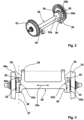
- Fig. 3
- zeigt eine weitere Ansicht auf die Portalachse des Drehgestells;
- Fig. 4
- zeigt eine Seitenansicht auf den Achsschenkel der Portalachse des Drehgestells.
- 1
- shows a perspective view of the bogie, which is shown only schematically;
- 2
- shows a perspective view of a portal axle of the bogie;
- 3
- shows another view of the portal axis of the bogie;
- 4
- shows a side view of the stub axle of the portal axle of the bogie.
Das in
Die Portalachse 20 umfasst eine im Querschnitt rechteckförmige Tragachse 22, die sich in einer Haupterstreckungsrichtung 22a erstreckt und endseitig jeweils einen Träger 24 (
Der Achsschenkel 32 umfasst eine erste Achsschulter 35 zur Aufnahme einer Federeinrichtung 37. Die Rahmenträger 4 weisen endseitig jeweils den Federarm 5 auf, der mit der Federeinrichtung 37 in Verbindung steht. Die Federarme 5 werden somit federnd an Stützflächen 35a der jeweils zugehörigen ersten Achsschulter 35 abgestützt. Die Federeinrichtung 37 umfasst einzelne Elastomerfederpakete 38, die jeweils durch Metallplatten 38a voneinander getrennt sind. Die erste Achsschulter 35, die der Aufnahme der Federeinrichtung 37 dient, und konkret der Normalenvektor 35b der Stützfläche 35a verläuft im Winkel α von etwa 45° zur Längsachse 27 des Schwenkarms 29.The
Gegenüberliegend zu der ersten Achsschulter 35 ist eine zweite Achsschulter 36 vorgesehen, die auf die erste Achsschulter 35 schräg zuläuft, sodass der Achsschenkel 32 in der Ansicht in etwa trapez- oder dreieckförmig ausgebildet ist. Durch den schrägen Verlauf der zweiten Achsschulter 36 in Richtung auf die erste Achsschulter 35 wird im Bereich der zweiten Achsschulter 36 ein Freiraum geschaffen, der bewirkt, dass der Drehwinkel des Wagenkastens relativ zum Drehgestell vergrößert wird, mit der Folge, dass ein solches Fahrzeug enge Kurven durchfahren kann.Opposite the
In diesem Zusammenhang bildet die Federeinrichtung 37 auf der ersten Achsschulter 35 die Primärfedereinrichtung, ohne dass, wie nach dem Stand der Technik teilweise vorgesehen, im Bereich der zweiten Achsschulter eine weitere Feder vorgesehen sein muss. Dies bewirkt ebenfalls, dass der zur Verfügung stehende Bauraum im Bereich der zweiten Achsschulter voll umfänglich einem größeren Drehwinkel zugutekommt.In this context, the
Aus
Bedingt durch die Anordnung des Schwenkarms 29 unter dem Achsschenkel 32 in Verbindung mit der schräg auf die erste Achsschulter 35 zulaufende zweite Achsschulter 36 wird somit nicht nur ein großer Drehwinkel zur Verfügung gestellt, sondern gleichfalls auch ein durchgehend ebener Boden, der aufgrund der geringen Höhe bedingt durch die Anordnung des Schwenkarmes 29 unterhalb des Achsschenkels 32, die niederflurige Ausgestaltung eines Fahrzeugs auch im Bodenbereich des Drehgestells 1 ermöglicht.Due to the arrangement of the
Claims (15)
- A portal axle (20) for a bogie (1) of a rail vehicle, in particular of a low floor rail vehicle, wherein the portal axle (20) has a respective axle journal (32) at both ends,
characterized in that
for the support of a frame (3) of the bogie of the rail vehicle• the portal axle (20) has a respective pivot arm (29) at both ends for the pivotable connection of the portal axle (20) to the frame (3); and• each of the two axle journals (32) has a first axle shoulder (35) having a spring device (37) arranged thereon for a resilient support of the frame (3) at a support surface (35a) of the axle shoulder (35),wherein the axle shoulder (35) and the pivot arm (29) are oriented toward one another such that a normal vector (35b) of the support surface (35a) and a longitudinal axis (27) of the pivot arm (20) include an angle (α) of > 0°, but < 90°. - A portal axle (20) in accordance with claim 1,
characterized in that
the portal axle (20) has at least one support axle (22) extending between the two axle journals (32). - A portal axle (20) in accordance with one of the preceding claims,
characterized in that
the pivot arm (29) has a bearing sleeve (30) for the supporting reception of the frame (3). - A portal axle (20) in accordance with one of the preceding claims,
characterized in that
the axle journal (32) tapers at least sectionally starting from the axle shoulder (35) in the direction of the longitudinal axis (27). - A portal axle (20) in accordance with claim 4,
characterized in that- on a projection onto a plane that includes the longitudinal axis (27) and a main direction of extent (22a) of a/the support axle (22) of the portal axle (20) -• a first side surface (32a) of the axle journal (32) disposed in the direction of the support axle (22) is inclined toward the main direction of extent (22a); and• an oppositely disposed second side surface (32b) of the axle journal (32) is oriented substantially transversely to the main direction of extent (22a) - A portal axle (20) in accordance with one of the preceding claims,
characterized in that
the at least one portal axle (20) has a respective support (24) at both ends for the linking of a/the support axle (22) of the portal axle (22). - A portal axle (20) in accordance with claim 6,
characterized in that
the axle journal (32) and/or the pivot art (29) is/are arranged on or at the support (24). - A portal axle (20) in accordance with one of the preceding claims,
characterized in that
the axle journal (32) has a second axle shoulder (36) whose front surface (36a) is inclined - in a projection onto a plane transverse to the main direction of extent (22a) of the support axle (22) - toward the support surface (35a) of the first axle shoulder (35). - A portal axle (20) in accordance with one of the preceding claims,
characterized in that
the axle journal (32) has a bearing element for the supporting reception of a wheel (33) of the portal axle (20). - A portal axle (20) in accordance with one of the preceding claims,
characterized in that
the spring device (37) has at least one, preferably a plurality of elastomer spring packages (38) arranged above one another. - A portal axle (20) in accordance with claim 10,
characterized in that
the stiffness of the elastomer spring packages (38) is similar or dissimilar. - A portal axle (20) in accordance with one of the preceding claims,
characterized in that
the angle (α) between the normal vector (35b) and the longitudinal axis (27) is in a range between 30° and 60°. - A bogie (1) for a rail vehicle, in particular a low floor rail vehicle, having two portal axles (20) in accordance with one of the preceding claims arranged spaced apart from one another in the longitudinal direction of the rail vehicle,
characterized in that
a frame (3) for the reception of a railcar body of the rail vehicle is provided between the portal axles (20) of the bogie (1), with a pivot bearing (9) optionally being provided for the rotatable reception of the railcar body. - A bogie (1) in accordance with claim 13,
characterized in that
the frame (3) is connected to the respective pivot arms (29) of the two portal axles (20), in particular by means of the bearing sleeves (30) of the pivot arms (29). - A bogie (1) in accordance with claim 13 or claim 14,
characterized in that
the frame (3) has two respective spring arms (5) at both ends that are connected to the respective spring device (37).
Priority Applications (1)
| Application Number | Priority Date | Filing Date | Title |
|---|---|---|---|
| EP20152390.9A EP3851355B1 (en) | 2020-01-17 | 2020-01-17 | Portal axle for a bogie of a rail vehicle |
Applications Claiming Priority (1)
| Application Number | Priority Date | Filing Date | Title |
|---|---|---|---|
| EP20152390.9A EP3851355B1 (en) | 2020-01-17 | 2020-01-17 | Portal axle for a bogie of a rail vehicle |
Publications (3)
| Publication Number | Publication Date |
|---|---|
| EP3851355A1 EP3851355A1 (en) | 2021-07-21 |
| EP3851355C0 EP3851355C0 (en) | 2023-06-07 |
| EP3851355B1 true EP3851355B1 (en) | 2023-06-07 |
Family
ID=69191857
Family Applications (1)
| Application Number | Title | Priority Date | Filing Date |
|---|---|---|---|
| EP20152390.9A Active EP3851355B1 (en) | 2020-01-17 | 2020-01-17 | Portal axle for a bogie of a rail vehicle |
Country Status (1)
| Country | Link |
|---|---|
| EP (1) | EP3851355B1 (en) |
Families Citing this family (1)
| Publication number | Priority date | Publication date | Assignee | Title |
|---|---|---|---|---|
| FR3129352B1 (en) * | 2021-11-25 | 2023-11-24 | Alstom Transp Tech | Compact rail vehicle bogie |
Family Cites Families (7)
| Publication number | Priority date | Publication date | Assignee | Title |
|---|---|---|---|---|
| DE4428038C1 (en) | 1994-08-08 | 1995-08-10 | Siemens Ag | Bogie truck for rail vehicle |
| DE102006044614A1 (en) * | 2006-09-19 | 2008-03-27 | Sames, Gerhold, Dipl.-Ing. | Wheel guiding unit for trailer and traction bogie of rail vehicles, particularly, for low-floor vehicles of regional and local traffic, has two connected transmission units, which are arranged on notional wheel axle |
| JP5322775B2 (en) * | 2009-05-26 | 2013-10-23 | 川崎重工業株式会社 | Low-floor railcar bogie, method for press-fitting and removing a fixed axle of the bogie |
| EP2669138B1 (en) * | 2012-05-30 | 2021-07-07 | Bombardier Transportation GmbH | Running gear frame for a rail vehicle |
| AT514373B1 (en) | 2013-05-02 | 2019-03-15 | Siemens Ag Oesterreich | Wheelset bearing for the wheelset of a rail vehicle with internally mounted bogie |
| IT201600088005A1 (en) | 2016-08-30 | 2018-03-02 | Lucchini Rs Spa | AXLE-AXLE OF RAILWAY AND RAILWAY VEHICLES WITH REDUCED FLOOR |
| DE102017128598B4 (en) | 2017-12-01 | 2019-10-31 | Andreas Fiedler | Arrangement for damping the roll and stabilizing a car body for land vehicles |
-
2020
- 2020-01-17 EP EP20152390.9A patent/EP3851355B1/en active Active
Also Published As
| Publication number | Publication date |
|---|---|
| EP3851355C0 (en) | 2023-06-07 |
| EP3851355A1 (en) | 2021-07-21 |
Similar Documents
| Publication | Publication Date | Title |
|---|---|---|
| DE2912533A1 (en) | AXLE SPRING | |
| EP3065958B1 (en) | Wheel suspension for a motor vehicle | |
| DE102005029641A1 (en) | Arm | |
| DE2246542B2 (en) | Suspension for vehicles | |
| EP1814746A1 (en) | Independent wheel suspension of a two-track vehicle | |
| DE202015008095U1 (en) | tandem axle | |
| EP3851355B1 (en) | Portal axle for a bogie of a rail vehicle | |
| DE1755070C3 (en) | Wheel suspension for automobiles | |
| DE102018207616B4 (en) | Wheel suspension for a motor vehicle | |
| DE10260060A1 (en) | Independent suspension with leaf spring for a motor vehicle | |
| DE102018005047A1 (en) | Suspension for a vehicle | |
| DE3442682C2 (en) | ||
| DE3221755A1 (en) | Bogie for a rail vehicle | |
| DE102012001377A1 (en) | Ballast wagon for a derrick crane | |
| WO2020221569A1 (en) | Independent wheel suspension for a two-track vehicle, axle and vehicle | |
| EP1118477A2 (en) | Wheel suspension | |
| DE102021121993B3 (en) | Wheel suspension for a motor vehicle and corresponding motor vehicle | |
| DE19853636B4 (en) | Arm | |
| EP1226058B1 (en) | Bogie for rail vehicles | |
| EP0697297A2 (en) | Twin axle unit of a utility vehicle with special leaf spring support member | |
| DE102013222443A1 (en) | Wheel suspension for a motor vehicle | |
| DE2127846C3 (en) | Bogie for rail vehicles | |
| DE102021131246A1 (en) | Active chassis | |
| DE102021125226A1 (en) | Wheel suspension with curved steering guide | |
| DE10025965A1 (en) | Suspension |
Legal Events
| Date | Code | Title | Description |
|---|---|---|---|
| PUAI | Public reference made under article 153(3) epc to a published international application that has entered the european phase |
Free format text: ORIGINAL CODE: 0009012 |
|
| STAA | Information on the status of an ep patent application or granted ep patent |
Free format text: STATUS: REQUEST FOR EXAMINATION WAS MADE |
|
| 17P | Request for examination filed |
Effective date: 20210128 |
|
| AK | Designated contracting states |
Kind code of ref document: A1 Designated state(s): AL AT BE BG CH CY CZ DE DK EE ES FI FR GB GR HR HU IE IS IT LI LT LU LV MC MK MT NL NO PL PT RO RS SE SI SK SM TR |
|
| GRAP | Despatch of communication of intention to grant a patent |
Free format text: ORIGINAL CODE: EPIDOSNIGR1 |
|
| STAA | Information on the status of an ep patent application or granted ep patent |
Free format text: STATUS: GRANT OF PATENT IS INTENDED |
|
| INTG | Intention to grant announced |
Effective date: 20221201 |
|
| GRAS | Grant fee paid |
Free format text: ORIGINAL CODE: EPIDOSNIGR3 |
|
| GRAA | (expected) grant |
Free format text: ORIGINAL CODE: 0009210 |
|
| STAA | Information on the status of an ep patent application or granted ep patent |
Free format text: STATUS: THE PATENT HAS BEEN GRANTED |
|
| AK | Designated contracting states |
Kind code of ref document: B1 Designated state(s): AL AT BE BG CH CY CZ DE DK EE ES FI FR GB GR HR HU IE IS IT LI LT LU LV MC MK MT NL NO PL PT RO RS SE SI SK SM TR |
|
| REG | Reference to a national code |
Ref country code: GB Ref legal event code: FG4D Free format text: NOT ENGLISH |
|
| REG | Reference to a national code |
Ref country code: CH Ref legal event code: EP Ref country code: AT Ref legal event code: REF Ref document number: 1574136 Country of ref document: AT Kind code of ref document: T Effective date: 20230615 Ref country code: DE Ref legal event code: R096 Ref document number: 502020003420 Country of ref document: DE |
|
| U01 | Request for unitary effect filed |
Effective date: 20230607 |
|
| U07 | Unitary effect registered |
Designated state(s): AT BE BG DE DK EE FI FR IT LT LU LV MT NL PT SE SI Effective date: 20230612 |
|
| REG | Reference to a national code |
Ref country code: LT Ref legal event code: MG9D |
|
| PG25 | Lapsed in a contracting state [announced via postgrant information from national office to epo] |
Ref country code: NO Free format text: LAPSE BECAUSE OF FAILURE TO SUBMIT A TRANSLATION OF THE DESCRIPTION OR TO PAY THE FEE WITHIN THE PRESCRIBED TIME-LIMIT Effective date: 20230907 Ref country code: ES Free format text: LAPSE BECAUSE OF FAILURE TO SUBMIT A TRANSLATION OF THE DESCRIPTION OR TO PAY THE FEE WITHIN THE PRESCRIBED TIME-LIMIT Effective date: 20230607 |
|
| PG25 | Lapsed in a contracting state [announced via postgrant information from national office to epo] |
Ref country code: RS Free format text: LAPSE BECAUSE OF FAILURE TO SUBMIT A TRANSLATION OF THE DESCRIPTION OR TO PAY THE FEE WITHIN THE PRESCRIBED TIME-LIMIT Effective date: 20230607 Ref country code: HR Free format text: LAPSE BECAUSE OF FAILURE TO SUBMIT A TRANSLATION OF THE DESCRIPTION OR TO PAY THE FEE WITHIN THE PRESCRIBED TIME-LIMIT Effective date: 20230607 Ref country code: GR Free format text: LAPSE BECAUSE OF FAILURE TO SUBMIT A TRANSLATION OF THE DESCRIPTION OR TO PAY THE FEE WITHIN THE PRESCRIBED TIME-LIMIT Effective date: 20230908 |
|
| PG25 | Lapsed in a contracting state [announced via postgrant information from national office to epo] |
Ref country code: SK Free format text: LAPSE BECAUSE OF FAILURE TO SUBMIT A TRANSLATION OF THE DESCRIPTION OR TO PAY THE FEE WITHIN THE PRESCRIBED TIME-LIMIT Effective date: 20230607 |
|
| PG25 | Lapsed in a contracting state [announced via postgrant information from national office to epo] |
Ref country code: IS Free format text: LAPSE BECAUSE OF FAILURE TO SUBMIT A TRANSLATION OF THE DESCRIPTION OR TO PAY THE FEE WITHIN THE PRESCRIBED TIME-LIMIT Effective date: 20231007 |
|
| PG25 | Lapsed in a contracting state [announced via postgrant information from national office to epo] |
Ref country code: SM Free format text: LAPSE BECAUSE OF FAILURE TO SUBMIT A TRANSLATION OF THE DESCRIPTION OR TO PAY THE FEE WITHIN THE PRESCRIBED TIME-LIMIT Effective date: 20230607 Ref country code: SK Free format text: LAPSE BECAUSE OF FAILURE TO SUBMIT A TRANSLATION OF THE DESCRIPTION OR TO PAY THE FEE WITHIN THE PRESCRIBED TIME-LIMIT Effective date: 20230607 Ref country code: RO Free format text: LAPSE BECAUSE OF FAILURE TO SUBMIT A TRANSLATION OF THE DESCRIPTION OR TO PAY THE FEE WITHIN THE PRESCRIBED TIME-LIMIT Effective date: 20230607 Ref country code: IS Free format text: LAPSE BECAUSE OF FAILURE TO SUBMIT A TRANSLATION OF THE DESCRIPTION OR TO PAY THE FEE WITHIN THE PRESCRIBED TIME-LIMIT Effective date: 20231007 Ref country code: CZ Free format text: LAPSE BECAUSE OF FAILURE TO SUBMIT A TRANSLATION OF THE DESCRIPTION OR TO PAY THE FEE WITHIN THE PRESCRIBED TIME-LIMIT Effective date: 20230607 |
|
| U20 | Renewal fee paid [unitary effect] |
Year of fee payment: 5 Effective date: 20240119 |
|
| PG25 | Lapsed in a contracting state [announced via postgrant information from national office to epo] |
Ref country code: PL Free format text: LAPSE BECAUSE OF FAILURE TO SUBMIT A TRANSLATION OF THE DESCRIPTION OR TO PAY THE FEE WITHIN THE PRESCRIBED TIME-LIMIT Effective date: 20230607 |
|
| PLBE | No opposition filed within time limit |
Free format text: ORIGINAL CODE: 0009261 |
|
| STAA | Information on the status of an ep patent application or granted ep patent |
Free format text: STATUS: NO OPPOSITION FILED WITHIN TIME LIMIT |