EP3849321B1 - Messvorrichtung und verfahren zur kontaktlosen analyse eines nahrungsmittelproduktes in einer produktionslinie - Google Patents
Messvorrichtung und verfahren zur kontaktlosen analyse eines nahrungsmittelproduktes in einer produktionslinie Download PDFInfo
- Publication number
- EP3849321B1 EP3849321B1 EP19782792.6A EP19782792A EP3849321B1 EP 3849321 B1 EP3849321 B1 EP 3849321B1 EP 19782792 A EP19782792 A EP 19782792A EP 3849321 B1 EP3849321 B1 EP 3849321B1
- Authority
- EP
- European Patent Office
- Prior art keywords
- dough
- jet
- lump
- fluid
- pressurized fluid
- Prior art date
- Legal status (The legal status is an assumption and is not a legal conclusion. Google has not performed a legal analysis and makes no representation as to the accuracy of the status listed.)
- Active
Links
Images





Classifications
-
- A—HUMAN NECESSITIES
- A21—BAKING; EDIBLE DOUGHS
- A21C—MACHINES OR EQUIPMENT FOR MAKING OR PROCESSING DOUGHS; HANDLING BAKED ARTICLES MADE FROM DOUGH
- A21C13/00—Provers, i.e. apparatus permitting dough to rise
-
- A—HUMAN NECESSITIES
- A21—BAKING; EDIBLE DOUGHS
- A21C—MACHINES OR EQUIPMENT FOR MAKING OR PROCESSING DOUGHS; HANDLING BAKED ARTICLES MADE FROM DOUGH
- A21C13/00—Provers, i.e. apparatus permitting dough to rise
- A21C13/02—Provers, i.e. apparatus permitting dough to rise with endless conveyors, e.g. for moving the dough pieces progressively through the prover
-
- G—PHYSICS
- G01—MEASURING; TESTING
- G01B—MEASURING LENGTH, THICKNESS OR SIMILAR LINEAR DIMENSIONS; MEASURING ANGLES; MEASURING AREAS; MEASURING IRREGULARITIES OF SURFACES OR CONTOURS
- G01B11/00—Measuring arrangements characterised by the use of optical techniques
- G01B11/14—Measuring arrangements characterised by the use of optical techniques for measuring distance or clearance between spaced objects or spaced apertures
-
- G—PHYSICS
- G01—MEASURING; TESTING
- G01B—MEASURING LENGTH, THICKNESS OR SIMILAR LINEAR DIMENSIONS; MEASURING ANGLES; MEASURING AREAS; MEASURING IRREGULARITIES OF SURFACES OR CONTOURS
- G01B13/00—Measuring arrangements characterised by the use of fluids
- G01B13/12—Measuring arrangements characterised by the use of fluids for measuring distance or clearance between spaced objects or spaced apertures
-
- G—PHYSICS
- G01—MEASURING; TESTING
- G01J—MEASUREMENT OF INTENSITY, VELOCITY, SPECTRAL CONTENT, POLARISATION, PHASE OR PULSE CHARACTERISTICS OF INFRARED, VISIBLE OR ULTRAVIOLET LIGHT; COLORIMETRY; RADIATION PYROMETRY
- G01J5/00—Radiation pyrometry, e.g. infrared or optical thermometry
-
- G—PHYSICS
- G01—MEASURING; TESTING
- G01N—INVESTIGATING OR ANALYSING MATERIALS BY DETERMINING THEIR CHEMICAL OR PHYSICAL PROPERTIES
- G01N11/00—Investigating flow properties of materials, e.g. viscosity, plasticity; Analysing materials by determining flow properties
-
- G—PHYSICS
- G01—MEASURING; TESTING
- G01N—INVESTIGATING OR ANALYSING MATERIALS BY DETERMINING THEIR CHEMICAL OR PHYSICAL PROPERTIES
- G01N33/00—Investigating or analysing materials by specific methods not covered by groups G01N1/00 - G01N31/00
- G01N33/02—Food
- G01N33/10—Starch-containing substances, e.g. dough
-
- G—PHYSICS
- G01—MEASURING; TESTING
- G01S—RADIO DIRECTION-FINDING; RADIO NAVIGATION; DETERMINING DISTANCE OR VELOCITY BY USE OF RADIO WAVES; LOCATING OR PRESENCE-DETECTING BY USE OF THE REFLECTION OR RERADIATION OF RADIO WAVES; ANALOGOUS ARRANGEMENTS USING OTHER WAVES
- G01S15/00—Systems using the reflection or reradiation of acoustic waves, e.g. sonar systems
- G01S15/02—Systems using the reflection or reradiation of acoustic waves, e.g. sonar systems using reflection of acoustic waves
- G01S15/06—Systems determining the position data of a target
- G01S15/08—Systems for measuring distance only
-
- G—PHYSICS
- G01—MEASURING; TESTING
- G01S—RADIO DIRECTION-FINDING; RADIO NAVIGATION; DETERMINING DISTANCE OR VELOCITY BY USE OF RADIO WAVES; LOCATING OR PRESENCE-DETECTING BY USE OF THE REFLECTION OR RERADIATION OF RADIO WAVES; ANALOGOUS ARRANGEMENTS USING OTHER WAVES
- G01S17/00—Systems using the reflection or reradiation of electromagnetic waves other than radio waves, e.g. lidar systems
- G01S17/02—Systems using the reflection of electromagnetic waves other than radio waves
- G01S17/06—Systems determining position data of a target
- G01S17/08—Systems determining position data of a target for measuring distance only
-
- G—PHYSICS
- G01—MEASURING; TESTING
- G01N—INVESTIGATING OR ANALYSING MATERIALS BY DETERMINING THEIR CHEMICAL OR PHYSICAL PROPERTIES
- G01N11/00—Investigating flow properties of materials, e.g. viscosity, plasticity; Analysing materials by determining flow properties
- G01N2011/0026—Investigating specific flow properties of non-Newtonian fluids
- G01N2011/004—Stress relaxation time
Definitions
- the invention relates to a measuring device which is configured for a contactless analysis of a lump of dough.
- the invention relates to a method for a contactless analysis of a 1ump of dough in a production line.
- US 2,147,024 describes a device for detecting the proofing condition of dough lumps, which are subjected to a proofing process in a proofing chamber. During the proofing process, the dough lumps experience an increase in volume.
- the device comprises an electrical switch which is provided on a framework which allows to adjust the position of the switch relative to a support surface for the dough lumps in the proofing chamber.
- the electrical switch is provided with a convex contact element which is adapted for engagement by dough raising there-below. When the dough has raised sufficiently to engage the contact element and deflect the electrical switch, the electrical switch actuates an alarm device signaling that the dough has raised to a desired height.
- EP 1 096 857 B1 describes a device comprising a distance sensor, associated with at least one of the dough lumps provided in the proofing chamber, which, at least when the thickness of the dough lump achieves a predetermined intended value, which is correlated with a desired degree of ripeness of the dough lump, produces a therefore characteristic output signal.
- the distance sensor is designed and/or arranged such that it detects the height of the dough lump above a support surface.
- the distance sensor is an ultra-sonic sensor which operates on the principle of the travel time lapse of ultra-sonic signals.
- the distance sensor is provided on a framework employable in the proofing chamber, which can be placed on the proofing sheet in the chamber.
- US 5,372,030 discloses a device and a method for determining a firmness or a ripeness of fruit.
- the device comprises a means to generate an impulsive jet of a fluid aimed at a surface of the object under test, a laser to generate a beam of coherent light aimed at the area on the surface of the object under test impacted by the fluid jet, a detector to sense the light reflected off of the surface of the object from the laser beam, an analyzer to determine the amount of deformation of the surface caused by the fluid jet based on the input to the detector, and a controller to coordinate the release of the impulsive jet with the analyzer.
- a disadvantage of the known device(s) is that they provide very limited information, in particular only information is obtained about the increase in volume of the dough lumps.
- the invention provides a device for performing an analysis of a lump of dough, as defined in claim 1.
- the device allows to apply a force to the position on the surface of a product by directing a jet of pressurized fluid to said position on the surface.
- the device comprises a distance sensor for measuring the distance between the device and the position of the surface, in particular at the position of the surface where the jet of pressurized fluid is directed to. Any deformation of the surface at said position where the jet of pressurized fluid is directed to can be measured by the distance sensor. In addition or alternatively, the decrease or removal of the deformation of the surface at said position where the jet of pressurized fluid had been directed to can be measured by the distance sensor.
- a dough is a visco-elastic material, which can be characterized by material parameters such as, inter alia , a viscosity and elasticity. This viscosity and elasticity is different for different types of dough and changes also during the production process due to the various treatments of the dough before the dough product is finally baked in an oven. In particular the structure of the dough may change during the mixing, kneading and proofing of the dough.
- the surface of the dough will develop a local deformation when a force is applied to said surface of the dough, and this deformation will at least partially disappear when the force is removed from said surface of the dough.
- This development and/or removal of the deformation can be monitored by means of the distance sensor.
- a measure of material properties such as viscosity and elasticity, can be determined, for example by analyzing the data with a mathematical deformation model.
- a device for contactless analysis is advantageous, in particular to substantially prevent contamination of and/or damage to the products.
- the device is spaced apart from the product and is not in contact with the product, and therefor also contamination of the device is at least substantially prevented.
- only the jet of pressurized fluid comes in contact with the product. Accordingly, it is preferred to use clean pressurized fluid and/or the filter the pressurized fluid before it is directed to the product.
- the distance sensor is configured for measuring the distance between the device and substantially a center of the position of the surface where the jet of pressurized fluid is directed to. This allows to measure the deformation of the surface of the product substantially in the center of the position where the jet of pressurized fluid applies a force to the surface of the product. In particular when analyzing dough products, the deformation of the surface of said dough product is substantially only at the position of the surface where the jet of pressurized fluid impinges on the dough product.
- the distance sensor is at least partially arranged in the nozzle, preferably substantially in the center of said nozzle.
- the distance sensor is at least partially arranged in the center of the jet of pressurized fluid coming out of the nozzle.
- the distance sensor can measure the distance between the device and the position where the jet of pressurized fluid impinges on the surface of the product, substantially independent from the distance between the product and the device.
- the distance sensor comprises an illuminating beam source for projecting a light beam to the position on the surface of the product, and a light collecting unit for receiving light reflected from said surface of the product, wherein the light collecting unit is configured for providing a measure of the distance between the light collecting unit and the position on the surface of the product where the light beam impinges on said surface.
- the device according to this embodiment comprises an optical distance sensor.
- the illuminating beam source is configured for projecting the light beam along a central axis of the jet of pressurized fluid from the nozzle.
- the illuminating beam source comprises a light delivering member which is arranged in the nozzle.
- the light delivering member may comprise a light source, such as a lamp, LED or Laser, or may comprise a optical fiber. Accordingly, the light beam travels along the central axis of the jet of pressurized fluid, and as a result the light beam is arranged substantially in the center of the position where the jet of pressurized fluid impinges on the surface of the product, independent from the distance between the product and the device.
- the light collecting unit comprises one or more lenses for projecting and/or imaging the light reflected from said surface of the product on a light sensor, preferably wherein the light sensor comprises a CCD sensor array.
- the light sensor comprises a CCD sensor array.
- the diameter of the light spot on the surface of the product will increase or decrease as a function of the distance between the device and the surface of the product.
- the one or more lenses are configured such that an optical axis of the one or more lenses is arranged at a sharp angle to the light beam.
- the optical axis is arranged to intersect the light beam at a distance from the device, preferably at or near a distance from the device where the surface of the product is expected. Accordingly, the position of the light spot in the image on the light sensor will move as a function of the distance between the device and the surface of the product.
- the device comprises a supply tube for supplying said fluid, wherein said supply tube comprises a first branch for providing at least part of said fluid in the supply tube to the light collecting unit.
- the device comprises a first supply tube for supplying said fluid, and a second supply tube for supplying a cleaning fluid to the light collecting unit.
- the cleaning fluid may be the same as the fluid used for the jet of pressurized fluid, or may be a different fluid.
- the later two embodiments are in particular advantageous in a dusty environment, because dust from said environment may accumulate on the optics of the sensor, such as the one or more lenses.
- the part of the fluid or cleaning fluid can be used for blowing dust away from the optics, and to clean the optics of the sensor.
- the distance sensor comprises an ultrasonic sensor comprising a transceiver or a combination of a transmitter and a receiver.
- ultrasonic sensors use sound rather than light for detection, they work in applications where light sensors may not.
- Ultrasonic sensors are advantageous for translucent products. Target color or reflectivity substantially does not affect ultrasonic sensors, which can also operate reliably in high-glare environments.
- ultrasonic sensors are not or to a lesser extend affected by dusty environments, for example as in a bread production line.
- At least the transmitter or the transceiver is at least partially arranged in the nozzle. In an embodiment, at least the transmitter or the transceiver is at least partially arranged substantially in the center of the nozzle. Accordingly, the sound or sound pulse from the transmitter or the transceiver travels substantially along the central axis of the jet of pressurized fluid, and as a result the sound or sound pulse is arranged for measuring the distance substantially in the center of the position where the jet of pressurized fluid impinges on the surface of the product, independent from the distance between the product and the device.
- the nozzle comprises one or more jet vectoring members, preferably wherein the one or more jet vectoring members are arranged inside said nozzle.
- the one or more jet vectoring members preferably comprises a series of separation walls which extend in a direction substantially parallel to a central axis of the jet or wherein the one or more jet vectoring members comprises a series of substantially parallel tubes which extend in a direction substantially parallel to a central axis of the jet.
- the vectoring members are arranged to provide a substantially parallel jet of pressurized air, at least in or near the measuring range. Such a substantially parallel jet of pressurized air, applies the same magnitude of force to the surface of the product, substantially independent of the distance between the device and the surface of the product, at least in said measuring range.
- the device comprises a temperature sensor, wherein the temperature sensor is configured for measuring a temperature of said product.
- the temperature sensor comprises a contactless temperature sensor.
- the temperature sensor comprises an infra-red temperature sensor.
- material properties of the products such as viscosity and elasticity, are temperature dependent. By also measuring the temperature of at least the surface of the product, the temperature of the product can be taken in consideration when determining the material properties.
- the device comprises a supply tube for supplying said fluid, wherein said supply tube comprises a second branch for providing at least part of said fluid in the supply tube to the temperature sensor.
- the device comprises a first supply tube for supplying said fluid, and a further supply tube for supplying a cleaning fluid to the temperature sensor.
- the later two embodiments are in particular advantageous in a dusty environment, because dust from said environment may accumulate on the temperature sensor.
- the part of the fluid or the cleaning fluid can be used for blowing dust away from the temperature sensor, and to clean the temperature sensor.
- the fluid comprises a gas, preferably wherein the fluid comprises nitrogen gas or air.
- the invention provides an assembly for processing a lump of dough, as defined in claim 10.
- the invention provides a method for a contactless analysis of a lump of dough, as defined in claim 11.
- the method according to the present invention applies a force to the position on the surface of a product by directing a jet of pressurized fluid to said position on the surface.
- the device comprises a distance sensor which measures the distance between the device and the position of the surface, in particular at the position of the surface where the jet of pressurized fluid impinges on the surface of the product. Any deformation of the surface at said position where the jet of pressurized fluid is directed to is measured by the distance sensor.
- Such a method is particularly advantageous for analyzing deformable products, such as dough products. Because of the viscosity and elasticity of dough, the surface of the dough will develop a deformation due to the applied force, and this deformation will at least partially disappear when the force is removed from said surface of the dough.
- the method of the present invention allows to monitor the development and/or removal of the deformation by means of the distance sensor. From said development and/or removal of the deformation of the surface by the jet or pressurized fluid, a measure of material properties such as viscosity and elasticity, can be determined, for example by fitting the data to a mathematical visco-elastic deformation model.
- the development and/or removal of the deformation of the surface of the product as measured by the distance sensor is analyzed by a real-time electronic processing system, which is configured for real-time fitting the data to said mathematical visco-elastic deformation model, and which provides a substantially real-time output of the material properties.
- the distance sensor measures the distance between the device and the position of the surface where the jet of pressurized fluid is directed to.
- the distance sensor acquires a series of measurements when said jet of pressurized fluid applies a force to the position on the surface of the product.
- the product such as a lump of dough
- the product comprises a deformable product, wherein the distance sensor measures the distance between the device and the position of the surface where the jet of pressurized fluid is directed to.
- the product is covered by a liquid coating, wherein the jet of pressurized fluid pushes away said liquid coating at the position on the surface of the product, wherein the distance sensor measures the distance between the device and the position of the surface where the jet of pressurized fluid is directed to, preferably before and during the jet of pressurized fluid pushes away said liquid coating.
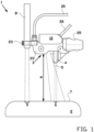
- Figure 1 shows a schematic side view of a first example of a device 1 for a contactless analysis of a product 2, in particular a food product such as a lump of dough.
- Said device 1 comprises a distance sensor 3 configured for measuring a distance d between the device 1 and the product 2.
- said device 1 comprises a nozzle 4 configured for directing a jet 5 of pressurized fluid to a position 6 on a surface 7 of said product 2.
- Said device 1 also comprises a temperature sensor 8, in particular an infra-red temperature sensor for sensing the temperature on a temperature measurement position 9 on the surface 7 of the product 2, which temperature measurement position 9 is arranged spaced apart from the position 6 where the jet 5 of pressurized fluid impinges on the surface 7
- the distance sensor 3 comprises a light collecting unit 12 for receiving light reflected from said surface 7 of the product 2.
- the light collecting unit 12 is configured for providing a measure of the distance d' between the light collecting unit 12 and the position 6 on the surface 7 of the product 2 where the light beam 11 impinges on said surface 7.
- the light collecting unit 12 comprises one or more lenses 13 for projecting and/or imaging a detection area 14 on said surface 7 of the product 2 on a light sensor 17 inside said light collecting unit 12.
- this light sensor 17 comprises a CCD sensor array.
- the one or more lenses 13 are configured such that an optical axis 15 of the one or more lenses 13 is arranged at a sharp angle ⁇ to an optical axis 16 of the light beam 11.
- the optical axis 15 is arranged to intersect the light beam 11 at a distance and spaced apart from the device 1. Accordingly, the position 6 of the light spot in the image on the light sensor 17 will move over the light sensor 17 as a function of the distance d between the device 1 and the surface 7 of the product 2.
- the device 1 further comprises a supply tube 20 for supplying said fluid to the device.
- the supply tube 20 is connected to the nozzle 4 to provide said pressurized fluid to the area inside the nozzle 4 and around the light delivering member 19.
- the pressurized fluid exits the nozzle 4 to provide the jet 5 of pressurized fluid towards the product 2.
- the device 1 is provided with a first branch for providing at least part of said fluid from the supply tube 20, via a first fluid output 21 to the light collecting unit 3, in particular to the lens 13.
- the pressurized fluid from the first fluid output 21 is arranged to blow away any dust from the lens 13, and substantially prevents contamination and/or the clogging up of the lens 13.
- the device 1 is further provided with a second branch for providing at least part of said fluid from the supply tube 20, via a second fluid output 22 to the temperature sensor 8.
- the pressurized fluid from the second fluid output 22 is arranged to blow away any dust from the temperature sensor 8, and substantially prevents contamination and/or the clogging up of the temperature sensor 8.
- first fluid output 21 and/or the second fluid output 22 may also be connected to a dedicated second supply tube (not shown) for providing a dedicated cleaning fluid.
- a dedicated second supply tube is, that the delivery of cleaning fluid can be independent of the delivery of fluid through the nozzle 4.
- the device 1 further comprises a mounting member 23 for holding the various components of the device 1.
- the mounting member 23 is provided with a connector 25 for mounting the device 1 to a frame of an assembly for processing products.
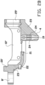
- FIG. 2B schematically shows the mounting member 23 which comprises a connector 20' for connecting the supply tube 20 and an integral tubing for providing a fluid connection between the connector 20' and the nozzle 4.
- the integral tubing also comprises said first and second branch for providing part of the fluid from the supply tube 20 to the first fluid output 21 and second fluid output 22.
- the mounting member 23 further comprises a distance sensor mounting position 12', a temperature sensor mounting position 8' and a connector mounting position 25'.
- the nozzle 4 is substantially integrally formed with the mounting member 23.
- the nozzle 4 can be provided with one or more jet vectoring members 24, which are arranged inside said nozzle 4 and surrounding said light delivery member 19.
- the one or more jet vectoring members 24 comprises a series of substantially parallel tubes which extend in a direction substantially parallel to a central axis of the jet.
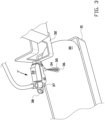
- Figure 3 shows the device 1 of figure 1 arranged in an assembly for the production of dough products, in particular for the production of bread.
- the lump of dough 30 for making the bread is arranged in a bread pan 31.
- multiple bread pans are arranged in a baking tray, and multiple baking trays are arranged in series to travel one behind the other through the various stations of the assembly.
- the device 1 is mounted to a frame 32 which frame 32 is arranged at a fix position along the assembly for producing dough products.
- the bread pans are temporarily held at a fixed position with respect to the device 1. This may be done by temporarily moving the device 1 substantially synchronous with the bread pan 31 or by temporarily stopping the bread pen 31 at the location of the device 1.
- the distance sensor 33 measures the distance between the device 1' and the surface of the dough 30.
- a light beam 34 is projected onto the surface of the dough 30.
- a light collecting unit inside said distance sensor 33 as describe with reference to figure 2A is configured for receiving light reflected from said surface of the dough 30.
- the light collecting unit is configured for providing a measure of the distance between the light collecting unit and the position on the surface of the product where the light beam impinges on said surface.
- a jet 35 of pressurized fluid in particular pressurized air, is activated to apply a force to an area 36 on the dough 30. Due to said force, the dough 30 will be slightly compressed in said area 36, which results in an increase in the distance between the dough 30 and the distance sensor 33.
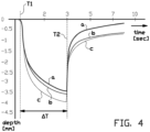
- Figure 4 schematically shows the development of the compression in the area 36 of the dough 30 as a function of time.
- the jet 35 of pressurized air is activated, and the graphs a, b, c show the development of a depression in the dough 30 as a function of time.
- the jet 35 of pressurized air is stopped, and the graphs a, b, c show the decrease or removal of the depression in the dough 30 as a function of time.
- the jet 35 of pressurized air acts on the dough 30 during a time interval ⁇ T of approximately 2 seconds (in this particular example).
- the distance sensor 33 measures the development of the deformation of the surface of the product 30 due to the applied force by the jet 35 and/or the removal of the deformation of the surface of the product 30 after the removal of said applied force.
- the various graphs a, b, c represent example measurements on different types of dough; in particular doughs with a different viscosity and/or elasticity. From these graphs a, b, c, and in particular from one or more measurement points of said graphs a, b, c, a measure for the viscosity and/or elasticity of the individual dough types can be determined.
- the depression in de dough 30 due to the jet 35 of air will decrease when the jet 35 of pressurized fluid is stopped, and in time the dough will substantially move back to its original shape. Accordingly, the position where the measurement has been performed is at least substantially invisible in the final product.
- the size of the depression in the dough 30 is small with respect to the size of the product.
- the depression has a diameter of about 5 or 6 mm and a depth of 3 to 5 mm.
- the device 1' comprises a second connector for connecting a supply tube for cleaning fluid (not shown), and a temperature sensor mounting position 38.
- FIG. 5 shows a schematic cross-section of a second example of a device according to the present invention.
- the device essentially uses the same mounting member 51 as shown in figure 2B (which is not essential for this embodiment) and comprises a connector 52 for connecting the supply tube and an integral tubing for providing a fluid connection between the connector 52 and the nozzle 53.
- the integral tubing also comprises a branch for providing part of the fluid from the connector 52 to the fluid output 54 for providing a cleaning fluid to a temperature sensor (not shown) which may be mounted in the temperature sensor mounting position 57.
- the mounting member 51 comprises a connector mounting position 59 for attaching a connector for connecting the mounting member 51.
- the device 50 comprises an ultrasonic sensor comprising at least a transmitter 55 and a receiver 56.
- the transmitter 55 is at least partially arranged in the nozzle 53, preferably substantially in the center of said nozzle 53.
- the nozzle 53 is substantially integrally formed with the mounting member 51.
- the nozzle 53 is provided with one or more jet vectoring members 58, which are arranged inside said nozzle 53 and surrounding said transmitter 55.
- the one or more jet vectoring members 58 comprises a series of substantially parallel tubes which extend in a direction substantially parallel to a central axis of the nozzle 53.
- Figure 6A shows a schematic view of a third example of a device 60 according to the present invention arranged in an assembly for processing products.
- the assembly comprises a conveying apparatus for conveying the products, in particular lumps of dough 61 in a baking pan 62, in a conveyance direction Y in the assembly, and wherein the device 60 comprises a nozzle 63 for producing a jet 64 of pressurized fluid with an elongated cross-section, as schematically indicated in figure 6 .
- the nozzle 63 is arranged such that a longitudinal direction L of said jet 64 with elongated cross-section is arranged substantially parallel to the conveyance direction Y.
- the distance sensor is arranged so that the light beam 65 is positioned at or near an upstream end 66 of the jet 64 with elongated cross-section, at least in the longitudinal direction of the jet 64 and with respect to the conveyance direction Y.
- the jet 64 with elongated cross-section is scanned over the surface of the dough 61.
- the part of the dough at the upstream end 66 experience the force of the jet 64 only for a short moment in time, whereas the part of the dough at the downstream end 67 travels along the conveyance direction Y and experiences the force of the jet 64 all the time this part is below the jet 64 with elongated cross-section.
- the deformation of the dough develops substantially similar as shown in the graphs in figure 4 .
- the development of the deformation of the surface of the dough 61 due to the jet 64 can be measured on a traveling product.
- Figure 6B shows a schematic view of an example of a device 60' according to the present invention arranged in an assembly for processing products.
- the assembly comprises a conveying apparatus for conveying the products, in particular lumps of dough 61' in a baking pan 62', in a conveyance direction Y in the assembly, and wherein the device 60' comprises a nozzle 63' for producing a jet 64' of pressurized fluid with an round cross-section, as schematically indicated in figure 6B .
- the distance sensor is arranged so that the light beam 65' is positioned downstream of the jet 64', at least in the longitudinal direction of the jet 64 and with respect to the conveyance direction Y.
- the jet 64' When the baking pan 62' with the dough 61' moves along the conveyance direction Y, and the device 60' is arranged substantially at a fixed position, the jet 64' provides a deformation of the surface of the dough 61 at said fixed position. Downstream of this position the jet 64' no longer deforms the surface of the dough 61' and the deformation decreases due to the elastic properties of the dough 61'. This decrease or removal of the deformation, downstream of the fixed position of the jet 64' is monitored by the distance sensor using the light beam 65' . Accordingly, during the travel of the dough 61' in the direction Y, the deformation of the dough decreases substantially similar as shown in the graphs in figure 4 after the time interval ⁇ T.
- the decrease or removal of the deformation of the surface of the dough 61' due to the jet 64' can be measured on a traveling product, in particular without the need of moving the device 60' along with the traveling product.
- the distance sensor in this example can also be separate and arranged downstream from the nozzle 63', for example configured to project a line shaped light beam 65' or a laserline on the surface of the dough 61' downstream of the position of the jet 64', and comprising a camera and an image analysis processor which is configured to analyze a deformation of said line of light due to the decrease or the removal of the deformation of the surface of said dough 61' by the jet 64' of compressed fluid.
- Figure 7 shows a schematic view of a fourth example of a device 70 according to the present invention arranged in an assembly for processing of said products.
- the assembly comprises a conveying apparatus for conveying the products, in particular lumps of dough 71 in a baking pan 72, in a conveyance direction Y in the assembly.
- the device 70 comprises a nozzle 73 for producing a jet 74 of pressurized fluid with an elongated cross-section, as schematically indicated in figure 7 .
- the nozzle 73 is arranged such that a longitudinal direction L of said jet 74 with elongated cross-section is arranged substantially parallel to the conveyance direction Y.
- the distance sensor is configured to provide an elongated light beam 75.
- the elongated light beam 75 is arranged such that a longitudinal direction L of said light beam 75 is arranged substantially parallel to the conveyance direction Y and substantially in the center of the jet 74 with elongated cross-section.
- the jet 74 with elongated cross-section is scanned over the surface of the dough 71.
- the part of the dough at the upstream end 76 experience the force of the jet 74 only for a short moment in time, whereas the part of the dough at the downstream end 77 travels along the conveyance direction Y and experiences the force of the jet 74 all the time this part is below the jet 74 with elongated cross-section.
- the deformation of the dough develops substantially similar as shown in the graphs in figure 4 .
- the deformation of the surface of the dough 71 represents the development of the deformation along the length of the jet 74; at the downstream end 77 the force starts to be applied and at the upstream end 78 the force has been applied during the time of traveling from the downstream end to the upstream end.
- the complete development of the deformation of the dough due to the jet 74 can be acquired with substantially one moment of measurement, for example by using a camera to image the elongated light beam 75 and using image analysis processor for retrieving distance information for the distortion of the light beam 75 due to the deformation of the surface of the dough 71. Accordingly, the development of the deformation of the surface of the dough 71 due to the jet 74 can be measured in one measurement and/or on a traveling product.
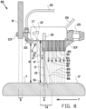
- Figure 8 shows a schematic view of a fifth example of a device 80 according to the present invention arranged in an assembly for processing of said products. It is noted that the device 80 is similar to the first example shown in figure 2A , but differs in that the device comprises a series of nozzles 4, 81, 82, 83, 84, 85 each one for producing a jet 5, 86, 87, 88, 89, 90 of pressurized fluid, wherein said series of nozzles are arranged on a line.
- the assembly comprises a conveying apparatus for conveying the products, in particular lumps of dough 2', in a conveyance direction Y in the assembly.
- the nozzles 4, 81, 82, 83, 84, 85 are arranged one behind the other is a longitudinal direction L substantially parallel to the conveyance direction Y.
- the distance sensor 12 is arranged so that the light beam 11 is positioned in the most upstream nozzle 4 with respect to the conveyance direction Y.
- the series of jets 5, 86, 87, 88, 89, 90 are scanned over the surface 7 of the dough 2'.
- the part of the dough at the upstream jet 5 experience the force of the jet 5 only for a short moment in time, whereas the part of the dough at the downstream jet 90 travels along the conveyance direction Y and experiences the accumulated force of the series of jets 5, 86, 87, 88, 89, 90.
- the deformation of the dough surface 7 develops substantially stepwise but in general similar as shown in the graphs in figure 4 .
- Figures 9A and 9B show a schematic view of an application of the device of figure 1 for analyzing liquid coatings 91 on a substantially solid carrier 2".
- the distance sensor 3 can measure the distance between the device 1 and the upper surface of the liquid coating 91, as schematically shown in figure 9A .
- the jet 5 of pressurized fluid is activated.
- the jet 5 of pressurized fluid is configured to push away said liquid coating 91 at the position 93 on the surface 7 of the carrier 2".
- the distance sensor 3 measures the distance between the device 1 and the surface 7 of the carrier 2", as schematically shown in figure 9B . Accordingly the thickness of the liquid coating 91 can be determined from the distance measurements before and during the jet 5 of pressurized fluid pushes away said liquid coating 91.
- the carrier 2" may be a solid carrier for measuring the properties of the liquid coating.
- the carrier 2" may also comprise a lump of dough with a coating of rice paste for the manufacturing of Tiger bread or Giraffe bread. In the latter case, the pressure of the jet 5 is carefully adjusted to push the rice past away, and not to provide an imprint on the dough.
- FIG 10 shows a schematic example of various steps in a production line for dough products.
- the industrial production of bread comprises the steps of mixing the components 100, kneading the dough 101, dividing the dough 102, forming or rounding the dough 103, proofing 104, baking the dough 105, de-panning the bread (in case the bread is baked in a baking pan) 106, cooling and/or freezing the bread 107, and packing the bread 108.
- the device of the present invention can be used to monitor a lump of dough at various process steps, in particular immediately after the various components have been mixed to form the dough, until just before the dough goes into the oven for baking the bread.
- the invention relates to a device and a method for a contactless analysis of a lump of dough as defined in claims 1 and 11.
Landscapes
- Physics & Mathematics (AREA)
- Engineering & Computer Science (AREA)
- General Physics & Mathematics (AREA)
- Life Sciences & Earth Sciences (AREA)
- Food Science & Technology (AREA)
- Health & Medical Sciences (AREA)
- Chemical & Material Sciences (AREA)
- Radar, Positioning & Navigation (AREA)
- Remote Sensing (AREA)
- Analytical Chemistry (AREA)
- Biochemistry (AREA)
- General Health & Medical Sciences (AREA)
- Immunology (AREA)
- Pathology (AREA)
- Computer Networks & Wireless Communication (AREA)
- Electromagnetism (AREA)
- Medicinal Chemistry (AREA)
- Acoustics & Sound (AREA)
- Spectroscopy & Molecular Physics (AREA)
- Perforating, Stamping-Out Or Severing By Means Other Than Cutting (AREA)
Claims (14)
- Eine Vorrichtung (1, 1`, 60, 60', 70, 80) zum Durchführen einer Analyse eines Teiglings (2, 2', 2", 30, 61, 61', 71), wobei die Vorrichtung umfasst:einen Abstandssensor (3, 12, 33), der konfiguriert ist zum kontaktlosen Messen eines Abstands (d, d') zwischen der Vorrichtung (1, 1`, 60, 60', 70, 80) und einer Oberfläche (7) des Teiglings (2, 2', 2", 30, 61, 61', 71) undeine Düse (4, 53, 63, 73, 81 - 85), die konfiguriert ist zum Richten eines Strahls (5, 35, 64, 74, 86 - 90) von mit Druck beaufschlagtem Fluid an eine Position (6, 93) auf der Oberfläche (7) des Teiglings (2, 2', 2", 30, 61, 61', 71), wobei der Strahl (5, 35, 64, 74, 86 - 90) von mit Druck beaufschlagtem Fluid konfiguriert ist einer Verformung der Oberfläche (7) des Teiglings (2, 2', 2", 30, 61, 61', 71) hervorzurufen,wobei der Abstandssensor (3, 12, 33) angeordnet ist zum Messen des Abstands (d, d') zwischen der Vorrichtung (1, 1', 60, 60', 70, 80) und der Position (6, 93) auf der Oberfläche (7) des Teiglings (2, 2', 2", 30, 61, 61', 71), an die der Strahl (5, 35, 64, 74, 86 - 90) von mit Druck beaufschlagtem Fluid gerichtet ist und/oder wurde, zum Überwachen einer Entwicklung und/oder einer Verringerung oder Entfernung der Verformung der Oberfläche (7) des Teiglings (2, 2', 2", 30, 61, 61', 71),wobei der Abstandssensor (3, 12, 33) umfasst:eine Beleuchtungsstrahlquelle (10) zum Projizieren eines Lichtstrahls (11) zumindest an die Position (6, 93) auf der Oberfläche (7) des Teiglings (2, 2', 2", 30, 61, 61', 71) undeine Lichtsammeleinheit (12) zum Empfangen von Licht, das von der Oberfläche (7) des Teiglings (2, 2', 2", 30, 61, 61', 71) reflektiert wird, wobei die Lichtsammeleinheit (12) konfiguriert ist zum Bereitstellen einer Messung des Abstands (d, d') zwischen der Lichtsammeleinheit (12) und der Position (6, 93) auf der Oberfläche (7) des Teiglings (2, 2', 2", 30, 61, 61', 71), wo der Lichtstrahl (11) auf die Oberfläche (7) auftrifft undwobei die Vorrichtung (1, 1', 60, 60', 70, 80) eine Zuführröhre (20) zum Zuführen des Fluids aufweist, wobei die Zuführröhre eine erste Verzweigung zum Bereitstellen zumindest eines Teils des Fluids in der Zuführröhre an die Lichtsammeleinheit (12) zum Wegblasen von Staub von der Lichtsammeleinheit (12) aufweist, oderwobei die Vorrichtung (1, 1`, 60, 60', 70, 80) eine erste Zuführröhre (20) zum Zuführen des Fluids und eine zweite Zuführröhre zum Zuführen eines Reinigungsfluids an die Lichtsammeleinheit (12) zum Wegblasen von Staub von der Lichtsammeleinheit (12) aufweist.
- Die Vorrichtung gemäß Anspruch 1, bei der der Abstandssensor (3, 12, 33) teilweise in der Düse (4, 53, 63, 73, 81 - 85) angeordnet ist, vorzugsweise im Wesentlichen in der Mitte der Düse (4, 53, 63, 73, 81 - 85).
- Die Vorrichtung gemäß Anspruch 1 oder 2, bei der die Lichtsammeleinheit (12) eine oder mehrere Linsen (13) aufweist zum Projizieren und/oder Abbilden des Lichts, das von der Oberfläche (7) des Teiglings (2, 2', 2", 30, 61, 61', 71) reflektiert wird, auf einen Lichtsensor (17), wobei der Lichtsensor (17) vorzugsweise ein CCD-Sensorarray aufweist, wobei die Beleuchtungsstrahlquelle (10) vorzugsweise konfiguriert ist zum Projizieren des Lichtstrahls (11) entlang einer Mittelachse (16) des Strahls (5, 35, 64, 74, 86 - 90) von mit Druck beaufschlagtem Fluid von der Düse (4, 53, 63, 73, 81 - 85), wobei die Beleuchtungsstrahlquelle (10) vorzugsweise ein Lichtzuführbauglied (19) aufweist, das in der Düse (4, 53, 63, 73, 81 - 85) angeordnet ist.
- Die Vorrichtung gemäß einem der Ansprüche 1 - 3, bei der die Düse (4, 53, 63, 73, 81 - 85) ein oder mehrere Strahlleitbauglieder (24, 58) aufweist, wobei das eine oder die mehreren Strahlleitbauglieder (24, 58) vorzugsweise in der Düse (4, 53, 63, 73, 81 - 85) angeordnet sind, wobei das eine oder die mehreren Strahlleitbauglieder (24, 58) vorzugsweise eine Reihe von Trennwänden aufweisen, die sich in einer Richtung im Wesentlichen parallel zu einer Mittelachse (16) des Strahls (5, 35, 64, 74, 86 - 90) erstrecken oder wobei das eine oder die mehreren Strahlleitbauglieder (24, 58) eine Reihe von im Wesentlichen parallelen Röhren aufweisen, die sich in einer Richtung im Wesentlichen parallel zu einer Mittelachse (16) des Strahls (5, 35, 64, 74, 86 - 90) erstrecken.
- Die Vorrichtung gemäß einem der Ansprüche 1 - 4, wobei die Vorrichtung (1, 1', 60, 60', 70, 80) einen Temperatursensor (8) aufweist, wobei der Temperatursensor (8) konfiguriert ist zum Messen einer Temperatur des Teiglings (2, 2', 2", 30, 61, 61', 71), wobei der Temperatursensor (8) vorzugsweise einen kontaktlosen Temperatursensor aufweist, wobei die Zuführröhre (20) vorzugsweise eine zweite Verzweigung zum Bereitstellen zumindest eines Teils des Fluids in der Zuführröhre (20) an den Temperatursensor (8) aufweist, oder wobei die Vorrichtung (1, 1', 60, 60', 70, 80) eine weitere Zuführröhre zum Zuführen eines Reinigungsfluids zu dem Temperatursensor (8) aufweist.
- Die Vorrichtung gemäß einem der Ansprüche 1 - 5, bei der das Fluid ein Gas aufweist, wobei das Fluid vorzugsweise Luft aufweist.
- Die Vorrichtung gemäß einem der Ansprüche 1 - 6, wobei die Vorrichtung (1, 1', 60, 60', 70, 80) eine Düse (4, 53, 63, 73, 81 - 85) zum Erzeugen eines Strahls (5, 35, 64, 74, 86 - 90) von mit Druck beaufschlagtem Fluid mit einem länglichen Querschnitt aufweist, wobei der längliche Querschnitt eine Längsrichtung (L) aufweist, wobei der Abstandssensor (3, 12, 33) vorzugsweise an oder nahe einem Ende des länglichen Querschnitts in der Längsrichtung (L) angeordnet ist.
- Die Vorrichtung gemäß einem der Ansprüche 1 - 6, wobei die Vorrichtung (1, 1`, 60, 60', 70, 80) eine Reihe von Düsen (4, 81 - 85) aufweist, jede zum Erzeugen eines Strahls (5, 35, 64, 74, 86 - 90) von mit Druck beaufschlagtem Fluid, wobei die Reihe von Düsen (4, 81 - 85) in einer im Wesentlichen linearen Reihe angeordnet sind, wobei der Abstandssensor (3, 12, 33) vorzugsweise in oder an der Düse (4, 81 - 85) angeordnet ist, die an einem Ende der Reihe von Düsen (4, 81 - 85) in der Reihe angeordnet ist.
- Die Vorrichtung gemäß einem der Ansprüche 1 - 6, wobei die Vorrichtung (1, 1', 60, 60', 70, 80) einen linienförmigen Beleuchtungsstrahl (75) aufweist, wobei der linienförmige Beleuchtungsstrahl (75) konfiguriert ist zum Bereitstellen einer Lichtlinie auf der Produktoberfläche (7), wobei der Abstandssensor (3, 12, 33) vorzugsweise eine Kamera und einen Bildanalyseprozessor aufweist, der dazu konfiguriert ist, eine Verformung der Lichtlinie (75) aufgrund der Entwicklung und/oder eine Entfernung der Verformung der Oberfläche (7) des Teiglings (2, 2', 2", 30, 61, 61', 71) durch den Strahl (5, 35, 64, 74, 86 - 90) von mit Druck beaufschlagtem Fluid zu analysieren.
- Eine Anordnung zum Verarbeiten von Teiglingen (2, 2', 2", 30, 61, 61', 71), wobei die Anordnung umfasst:eine Verarbeitungs- und/oder Fördervorrichtung für die Teiglinge (2, 2', 2", 30, 61, 61', 71) undeine Vorrichtung (1, 1', 60, 60', 70, 80) zum Durchführen einer Analyse eines Teiglings (2, 2', 2", 30, 61, 61', 71) gemäß einem der Ansprüche 1 - 9,wobei die Vorrichtung (1, 1', 60, 60', 70, 80) angeordnet ist zum Richten des Strahls (5, 35, 64, 74, 86 - 90) von mit Druck beaufschlagtem Fluid an eine Position (6, 93) auf einer Oberfläche (7) von einem der Teiglinge (2, 2', 2", 30, 61, 61', 71) in der Anordnung.
- Ein Verfahren für eine kontaktlose Analyse eines Teiglings (2, 2', 2", 30, 61, 61', 71), wobei das Verfahren folgende Schritte aufweist:Bereitstellen einer Vorrichtung (1, 1`, 60, 60', 70, 80), die einen Abstandssensor (3, 12, 33) aufweist,kontaktloses Messen eines Abstands (d, d') zwischen der Vorrichtung (1, 1`, 60, 60', 70, 80) und einer Oberfläche (7) des Teiglings (2, 2', 2", 30, 61, 61', 71) unter Verwendung des Abstandssensors (3, 12, 33),dadurch gekennzeichnet, dass das Verfahren ferner folgende Schritte aufweist:Richten eines Strahls (5, 35, 64, 74, 86 - 90) von mit Druck beaufschlagtem Fluid, um eine Kraft an eine Position (6, 93) auf der Oberfläche (7) des Teiglings (2, 2', 2", 30, 61, 61', 71) anzulegen, wobei der Strahl (5, 35, 64, 74, 86 - 90) von mit Druck beaufschlagtem Fluid dazu konfiguriert ist, eine Verformung der Oberfläche (7) des Teiglings (2, 2', 2", 30, 61, 61', 71) bereitzustellen, undwobei der Abstandssensor (3, 12, 33) den Abstand (d, d') zwischen der Vorrichtung (1, 1', 60, 60', 70, 80) und der Oberfläche (7) des Teiglings (2, 2', 2", 30, 61, 61', 71) an der Position (6, 93) der Verformung der Oberfläche (7) des Teiglings (2, 2', 2", 30, 61, 61', 71) aufgrund der angelegten Kraft und/oder aufgrund der Entfernung der angelegten Kraft misst.
- Das Verfahren gemäß Anspruch 11, bei dem der Teigling (2, 2', 2", 30, 61, 61', 71) mit einer flüssigen Beschichtung bedeckt ist, wobei der Strahl (5, 35, 64, 74, 86 - 90) von mit Druck beaufschlagtem Fluid die flüssige Beschichtung (91) an der Position (6, 93) auf der Oberfläche des Teiglings (2, 2', 2", 30, 61, 61', 71) wegdrückt, wobei der Abstandssensor (3, 12, 33) den Abstand (d, d') zwischen der Vorrichtung (1, 1', 60, 60', 70, 80) und der Position (6, 93) der Oberfläche (7) misst, an die der Strahl (5, 35, 64, 74, 86 - 90) von mit Druck beaufschlagtem Fluid gerichtet ist, vorzugsweise bevor und während der Strahl (5, 35, 64, 74, 86 - 90) von mit Druck beaufschlagtem Fluid die flüssige Beschichtung (91) wegdrückt.
- Das Verfahren gemäß Anspruch 11 oder Anspruch 12, wobei das Verfahren das Verwenden der Vorrichtung gemäß einem der Ansprüche 1 - 9 zum Durchführen der Analyse des Teiglings (2, 2', 2", 30, 61, 61', 71) aufweist.
- Das Verfahren gemäß einem der Ansprüche 11, 12 oder 13, bei dem das Verfahren ferner folgende Schritte aufweist:Überwachen der Entwicklung und/oder Entfernung der Verformung durch den Abstandssensor undBestimmen eines Maßes einer Viskosität und/oder Elastizität des Teigs von der Entwicklung und/oder Entfernung der Verformung der Oberfläche des Teiglings (2, 2', 2", 30, 61, 61', 71) durch den Strahl von mit Druck beaufschlagtem Fluid.
Applications Claiming Priority (2)
| Application Number | Priority Date | Filing Date | Title |
|---|---|---|---|
| NL2021642A NL2021642B1 (en) | 2018-09-14 | 2018-09-14 | Measuring device and method for a contactless analysis of a product in a production line |
| PCT/NL2019/050601 WO2020055258A1 (en) | 2018-09-14 | 2019-09-16 | Measuring device and method for a contactless analysis of a food product in a production line |
Publications (3)
| Publication Number | Publication Date |
|---|---|
| EP3849321A1 EP3849321A1 (de) | 2021-07-21 |
| EP3849321B1 true EP3849321B1 (de) | 2024-10-16 |
| EP3849321C0 EP3849321C0 (de) | 2024-10-16 |
Family
ID=63966037
Family Applications (1)
| Application Number | Title | Priority Date | Filing Date |
|---|---|---|---|
| EP19782792.6A Active EP3849321B1 (de) | 2018-09-14 | 2019-09-16 | Messvorrichtung und verfahren zur kontaktlosen analyse eines nahrungsmittelproduktes in einer produktionslinie |
Country Status (6)
| Country | Link |
|---|---|
| US (1) | US11927583B2 (de) |
| EP (1) | EP3849321B1 (de) |
| AU (1) | AU2019337344B2 (de) |
| CA (1) | CA3112797A1 (de) |
| NL (1) | NL2021642B1 (de) |
| WO (1) | WO2020055258A1 (de) |
Families Citing this family (3)
| Publication number | Priority date | Publication date | Assignee | Title |
|---|---|---|---|---|
| NL2021642B1 (en) * | 2018-09-14 | 2020-05-06 | Kaak Groep B V | Measuring device and method for a contactless analysis of a product in a production line |
| NL2025143B1 (en) * | 2020-03-16 | 2021-10-27 | Kaak Groep B V | Measuring device and method for a contactless analysis of a food product in a production line |
| CN111528247A (zh) * | 2020-05-13 | 2020-08-14 | 马奴海 | 一种发酵面制品研发检测用食品发酵箱 |
Family Cites Families (10)
| Publication number | Priority date | Publication date | Assignee | Title |
|---|---|---|---|---|
| US2147024A (en) | 1939-02-14 | Bread raising cabinet | ||
| EP0214100A1 (de) * | 1985-09-02 | 1987-03-11 | Alcan Rorschach AG | Verfahren zum berührungslosen Messen eines Abstandes, Abstandsmesselement, Verfahren zum kontinuierlichen Messen der Planheit von Folien, Element zum Messen der Planheit von Folien sowie Verfahren zum messen der Dicke eines starren Körpers |
| AT393914B (de) * | 1990-01-09 | 1992-01-10 | Haas Franz Waffelmasch | Verfahren und vorrichtung zum pruefen von elastischen gebaeckscheiben |
| DE9001451U1 (de) * | 1990-02-08 | 1991-07-18 | Kuka Schweissanlagen + Roboter Gmbh, 8900 Augsburg | Programmierhilfe für einen mehrachsigen Manipulator |
| US5372030A (en) * | 1993-09-15 | 1994-12-13 | The University Of Georgia Research Foundation, Inc. | Non-destructive firmness measuring device |
| DE19831635A1 (de) * | 1998-07-15 | 2000-01-20 | Thomas Atzinger | Einrichtung zur Erfassung des Gärungszustandes von Teiglingen |
| DE10048749A1 (de) * | 2000-09-29 | 2002-04-11 | Josef Schucker | Anordnung zum Aufbringen von Klebstoff auf ein Werkstück |
| CN108956376B (zh) * | 2018-05-08 | 2020-04-28 | 中国农业大学 | 一种食品流变特性检测系统 |
| CN108956377B (zh) * | 2018-05-08 | 2020-03-10 | 中国农业大学 | 一种食品流变特性检测方法 |
| NL2021642B1 (en) * | 2018-09-14 | 2020-05-06 | Kaak Groep B V | Measuring device and method for a contactless analysis of a product in a production line |
-
2018
- 2018-09-14 NL NL2021642A patent/NL2021642B1/en not_active IP Right Cessation
-
2019
- 2019-09-16 US US17/276,268 patent/US11927583B2/en active Active
- 2019-09-16 WO PCT/NL2019/050601 patent/WO2020055258A1/en not_active Ceased
- 2019-09-16 EP EP19782792.6A patent/EP3849321B1/de active Active
- 2019-09-16 AU AU2019337344A patent/AU2019337344B2/en active Active
- 2019-09-16 CA CA3112797A patent/CA3112797A1/en active Pending
Also Published As
| Publication number | Publication date |
|---|---|
| WO2020055258A1 (en) | 2020-03-19 |
| US11927583B2 (en) | 2024-03-12 |
| AU2019337344B2 (en) | 2024-12-19 |
| AU2019337344A1 (en) | 2021-04-08 |
| BR112021004773A2 (pt) | 2021-08-03 |
| EP3849321C0 (de) | 2024-10-16 |
| CA3112797A1 (en) | 2020-03-19 |
| EP3849321A1 (de) | 2021-07-21 |
| US20220026408A1 (en) | 2022-01-27 |
| NL2021642B1 (en) | 2020-05-06 |
Similar Documents
| Publication | Publication Date | Title |
|---|---|---|
| US11927583B2 (en) | Measuring device and method for a contactless analysis of a food product in a production line | |
| US6541757B2 (en) | Detection assembly for detecting dispensed material | |
| EP3823459B1 (de) | Positionskontrolle extrudierter produkte für speiseeisprodukte | |
| US5142648A (en) | Method and apparatus for paint inspection | |
| EP3457113B1 (de) | Fremdobjekt-prüfvorrichtung und fremdobjekt-prüfverfahren | |
| CA2171979A1 (en) | Non-destructive firmness measuring device | |
| KR20080011202A (ko) | 유리 절단 에너지의 온-라인 측정을 위한 음파방출 시스템및 방법 | |
| JPH11352021A (ja) | 噴射弁の噴霧パターン検査装置 | |
| US20140323843A1 (en) | Tonometer calibration tool | |
| JP2000014642A (ja) | 非接触式眼圧計 | |
| NL2025143B1 (en) | Measuring device and method for a contactless analysis of a food product in a production line | |
| BR112021004773B1 (pt) | Método para uma análise sem contato de um produto de massa | |
| WO2016203379A1 (en) | Improved plant for spraying skins and the like | |
| US12608789B2 (en) | Systems and methods for automated in-line plunger depth measurement | |
| EP4445118A1 (de) | Vorrichtung zur beleuchtung von materie | |
| CN119290574B (zh) | 一种座垫面套压痕检测装置及检测方法 | |
| JP2003294598A (ja) | 弾性特性の計測方法及び計測システム | |
| JP7742202B2 (ja) | 吐出状態検査方法、吐出状態検査装置および液滴検査システム | |
| JP2005164427A (ja) | 柔らかさ測定方法及び柔らかさ測定装置 | |
| JPH05312526A (ja) | レーザー計測器 | |
| WO1989003987A1 (en) | Apparatus for quality control of hypodermic needles | |
| JPH0716209A (ja) | 非接触眼圧計 | |
| TW201927421A (zh) | 水果檢測設備 | |
| JPH0737886B2 (ja) | 熱間ビレツト寸法測定装置 |
Legal Events
| Date | Code | Title | Description |
|---|---|---|---|
| STAA | Information on the status of an ep patent application or granted ep patent |
Free format text: STATUS: UNKNOWN |
|
| STAA | Information on the status of an ep patent application or granted ep patent |
Free format text: STATUS: THE INTERNATIONAL PUBLICATION HAS BEEN MADE |
|
| PUAI | Public reference made under article 153(3) epc to a published international application that has entered the european phase |
Free format text: ORIGINAL CODE: 0009012 |
|
| STAA | Information on the status of an ep patent application or granted ep patent |
Free format text: STATUS: REQUEST FOR EXAMINATION WAS MADE |
|
| 17P | Request for examination filed |
Effective date: 20210311 |
|
| AK | Designated contracting states |
Kind code of ref document: A1 Designated state(s): AL AT BE BG CH CY CZ DE DK EE ES FI FR GB GR HR HU IE IS IT LI LT LU LV MC MK MT NL NO PL PT RO RS SE SI SK SM TR |
|
| DAV | Request for validation of the european patent (deleted) | ||
| DAX | Request for extension of the european patent (deleted) | ||
| RIN1 | Information on inventor provided before grant (corrected) |
Inventor name: KOKOTTI. MARIA Inventor name: VAN DER BORG, LODEWIJK STEPHANUS MARGARETHA JOSEPH Inventor name: VEROUDEN, FRANCISCUS QUIRINUS FREDRIK Inventor name: RABEN, SJOERD GERARDUS JOHANNES Inventor name: VAN ZUTPHEN, PIETER PETRUS HENDRIKUS |
|
| RIN1 | Information on inventor provided before grant (corrected) |
Inventor name: KOKKOTI, MARIA Inventor name: VAN DER BORG, LODEWIJK STEPHANUS MARGARETHA JOSEPH Inventor name: VEROUDEN, FRANCISCUS QUIRINUS FREDRIK Inventor name: RABEN, SJOERD GERARDUS JOHANNES Inventor name: VAN ZUTPHEN, PIETER PETRUS HENDRIKUS |
|
| STAA | Information on the status of an ep patent application or granted ep patent |
Free format text: STATUS: EXAMINATION IS IN PROGRESS |
|
| 17Q | First examination report despatched |
Effective date: 20221115 |
|
| REG | Reference to a national code |
Ref country code: DE Ref legal event code: R079 Free format text: PREVIOUS MAIN CLASS: A21C0013000000 Ipc: G01N0033100000 Ref country code: DE Ref legal event code: R079 Ref document number: 602019060533 Country of ref document: DE Free format text: PREVIOUS MAIN CLASS: A21C0013000000 Ipc: G01N0033100000 |
|
| RIC1 | Information provided on ipc code assigned before grant |
Ipc: G01B 11/14 20060101ALI20231116BHEP Ipc: G01B 13/12 20060101ALI20231116BHEP Ipc: A21C 13/00 20060101ALI20231116BHEP Ipc: G01N 33/10 20060101AFI20231116BHEP |
|
| GRAP | Despatch of communication of intention to grant a patent |
Free format text: ORIGINAL CODE: EPIDOSNIGR1 |
|
| STAA | Information on the status of an ep patent application or granted ep patent |
Free format text: STATUS: GRANT OF PATENT IS INTENDED |
|
| INTG | Intention to grant announced |
Effective date: 20240104 |
|
| GRAJ | Information related to disapproval of communication of intention to grant by the applicant or resumption of examination proceedings by the epo deleted |
Free format text: ORIGINAL CODE: EPIDOSDIGR1 |
|
| STAA | Information on the status of an ep patent application or granted ep patent |
Free format text: STATUS: EXAMINATION IS IN PROGRESS |
|
| GRAP | Despatch of communication of intention to grant a patent |
Free format text: ORIGINAL CODE: EPIDOSNIGR1 |
|
| STAA | Information on the status of an ep patent application or granted ep patent |
Free format text: STATUS: GRANT OF PATENT IS INTENDED |
|
| INTC | Intention to grant announced (deleted) | ||
| INTG | Intention to grant announced |
Effective date: 20240412 |
|
| GRAJ | Information related to disapproval of communication of intention to grant by the applicant or resumption of examination proceedings by the epo deleted |
Free format text: ORIGINAL CODE: EPIDOSDIGR1 |
|
| STAA | Information on the status of an ep patent application or granted ep patent |
Free format text: STATUS: EXAMINATION IS IN PROGRESS |
|
| GRAS | Grant fee paid |
Free format text: ORIGINAL CODE: EPIDOSNIGR3 |
|
| STAA | Information on the status of an ep patent application or granted ep patent |
Free format text: STATUS: GRANT OF PATENT IS INTENDED |
|
| GRAP | Despatch of communication of intention to grant a patent |
Free format text: ORIGINAL CODE: EPIDOSNIGR1 |
|
| INTC | Intention to grant announced (deleted) | ||
| INTG | Intention to grant announced |
Effective date: 20240726 |
|
| GRAA | (expected) grant |
Free format text: ORIGINAL CODE: 0009210 |
|
| STAA | Information on the status of an ep patent application or granted ep patent |
Free format text: STATUS: THE PATENT HAS BEEN GRANTED |
|
| AK | Designated contracting states |
Kind code of ref document: B1 Designated state(s): AL AT BE BG CH CY CZ DE DK EE ES FI FR GB GR HR HU IE IS IT LI LT LU LV MC MK MT NL NO PL PT RO RS SE SI SK SM TR |
|
| REG | Reference to a national code |
Ref country code: GB Ref legal event code: FG4D |
|
| REG | Reference to a national code |
Ref country code: CH Ref legal event code: EP |
|
| REG | Reference to a national code |
Ref country code: IE Ref legal event code: FG4D |
|
| REG | Reference to a national code |
Ref country code: DE Ref legal event code: R096 Ref document number: 602019060533 Country of ref document: DE |
|
| U01 | Request for unitary effect filed |
Effective date: 20241023 |
|
| U07 | Unitary effect registered |
Designated state(s): AT BE BG DE DK EE FI FR IT LT LU LV MT NL PT RO SE SI Effective date: 20241106 |
|
| PG25 | Lapsed in a contracting state [announced via postgrant information from national office to epo] |
Ref country code: HR Free format text: LAPSE BECAUSE OF FAILURE TO SUBMIT A TRANSLATION OF THE DESCRIPTION OR TO PAY THE FEE WITHIN THE PRESCRIBED TIME-LIMIT Effective date: 20241016 Ref country code: IS Free format text: LAPSE BECAUSE OF FAILURE TO SUBMIT A TRANSLATION OF THE DESCRIPTION OR TO PAY THE FEE WITHIN THE PRESCRIBED TIME-LIMIT Effective date: 20250216 |
|
| PG25 | Lapsed in a contracting state [announced via postgrant information from national office to epo] |
Ref country code: ES Free format text: LAPSE BECAUSE OF FAILURE TO SUBMIT A TRANSLATION OF THE DESCRIPTION OR TO PAY THE FEE WITHIN THE PRESCRIBED TIME-LIMIT Effective date: 20241016 |
|
| PG25 | Lapsed in a contracting state [announced via postgrant information from national office to epo] |
Ref country code: NO Free format text: LAPSE BECAUSE OF FAILURE TO SUBMIT A TRANSLATION OF THE DESCRIPTION OR TO PAY THE FEE WITHIN THE PRESCRIBED TIME-LIMIT Effective date: 20250116 |
|
| PG25 | Lapsed in a contracting state [announced via postgrant information from national office to epo] |
Ref country code: GR Free format text: LAPSE BECAUSE OF FAILURE TO SUBMIT A TRANSLATION OF THE DESCRIPTION OR TO PAY THE FEE WITHIN THE PRESCRIBED TIME-LIMIT Effective date: 20250117 |
|
| PG25 | Lapsed in a contracting state [announced via postgrant information from national office to epo] |
Ref country code: PL Free format text: LAPSE BECAUSE OF FAILURE TO SUBMIT A TRANSLATION OF THE DESCRIPTION OR TO PAY THE FEE WITHIN THE PRESCRIBED TIME-LIMIT Effective date: 20241016 |
|
| PG25 | Lapsed in a contracting state [announced via postgrant information from national office to epo] |
Ref country code: RS Free format text: LAPSE BECAUSE OF FAILURE TO SUBMIT A TRANSLATION OF THE DESCRIPTION OR TO PAY THE FEE WITHIN THE PRESCRIBED TIME-LIMIT Effective date: 20250116 |
|
| PG25 | Lapsed in a contracting state [announced via postgrant information from national office to epo] |
Ref country code: SM Free format text: LAPSE BECAUSE OF FAILURE TO SUBMIT A TRANSLATION OF THE DESCRIPTION OR TO PAY THE FEE WITHIN THE PRESCRIBED TIME-LIMIT Effective date: 20241016 |
|
| PG25 | Lapsed in a contracting state [announced via postgrant information from national office to epo] |
Ref country code: SK Free format text: LAPSE BECAUSE OF FAILURE TO SUBMIT A TRANSLATION OF THE DESCRIPTION OR TO PAY THE FEE WITHIN THE PRESCRIBED TIME-LIMIT Effective date: 20241016 |
|
| PG25 | Lapsed in a contracting state [announced via postgrant information from national office to epo] |
Ref country code: CZ Free format text: LAPSE BECAUSE OF FAILURE TO SUBMIT A TRANSLATION OF THE DESCRIPTION OR TO PAY THE FEE WITHIN THE PRESCRIBED TIME-LIMIT Effective date: 20241016 |
|
| PLBE | No opposition filed within time limit |
Free format text: ORIGINAL CODE: 0009261 |
|
| STAA | Information on the status of an ep patent application or granted ep patent |
Free format text: STATUS: NO OPPOSITION FILED WITHIN TIME LIMIT |
|
| 26N | No opposition filed |
Effective date: 20250717 |
|
| U20 | Renewal fee for the european patent with unitary effect paid |
Year of fee payment: 7 Effective date: 20250924 |
|
| REG | Reference to a national code |
Ref country code: CH Ref legal event code: H13 Free format text: ST27 STATUS EVENT CODE: U-0-0-H10-H13 (AS PROVIDED BY THE NATIONAL OFFICE) Effective date: 20260504 |