EP3849072A1 - Leistungsumwandlungsvorrichtung und leistungsumwandlungsverfahren - Google Patents
Leistungsumwandlungsvorrichtung und leistungsumwandlungsverfahren Download PDFInfo
- Publication number
- EP3849072A1 EP3849072A1 EP19857156.4A EP19857156A EP3849072A1 EP 3849072 A1 EP3849072 A1 EP 3849072A1 EP 19857156 A EP19857156 A EP 19857156A EP 3849072 A1 EP3849072 A1 EP 3849072A1
- Authority
- EP
- European Patent Office
- Prior art keywords
- power
- power semiconductor
- terminal
- semiconductor elements
- conversion device
- Prior art date
- Legal status (The legal status is an assumption and is not a legal conclusion. Google has not performed a legal analysis and makes no representation as to the accuracy of the status listed.)
- Granted
Links
- 238000006243 chemical reaction Methods 0.000 title claims abstract description 64
- 238000000034 method Methods 0.000 title claims description 3
- 239000004065 semiconductor Substances 0.000 claims abstract description 61
- 230000003071 parasitic effect Effects 0.000 claims abstract description 10
- 239000003990 capacitor Substances 0.000 claims description 23
- 238000005096 rolling process Methods 0.000 claims description 10
- 230000007704 transition Effects 0.000 claims description 6
- 230000003247 decreasing effect Effects 0.000 claims description 4
- 230000015556 catabolic process Effects 0.000 abstract 1
- 238000006731 degradation reaction Methods 0.000 abstract 1
- 238000009499 grossing Methods 0.000 description 20
- 238000004804 winding Methods 0.000 description 9
- 238000010586 diagram Methods 0.000 description 8
- 230000007423 decrease Effects 0.000 description 5
- 230000002542 deteriorative effect Effects 0.000 description 5
- 230000005669 field effect Effects 0.000 description 3
- 238000005286 illumination Methods 0.000 description 3
- 230000004044 response Effects 0.000 description 3
- 229910052710 silicon Inorganic materials 0.000 description 3
- 239000010703 silicon Substances 0.000 description 3
- HBMJWWWQQXIZIP-UHFFFAOYSA-N silicon carbide Chemical compound [Si+]#[C-] HBMJWWWQQXIZIP-UHFFFAOYSA-N 0.000 description 3
- 229910010271 silicon carbide Inorganic materials 0.000 description 3
- 230000006866 deterioration Effects 0.000 description 2
- 238000012986 modification Methods 0.000 description 2
- 230000004048 modification Effects 0.000 description 2
- 238000005549 size reduction Methods 0.000 description 2
- 230000003068 static effect Effects 0.000 description 2
- 229910002601 GaN Inorganic materials 0.000 description 1
- JMASRVWKEDWRBT-UHFFFAOYSA-N Gallium nitride Chemical compound [Ga]#N JMASRVWKEDWRBT-UHFFFAOYSA-N 0.000 description 1
- 230000008901 benefit Effects 0.000 description 1
- 229910003460 diamond Inorganic materials 0.000 description 1
- 239000010432 diamond Substances 0.000 description 1
- 230000000694 effects Effects 0.000 description 1
- 230000001141 propulsive effect Effects 0.000 description 1
- 230000009467 reduction Effects 0.000 description 1
Images


Classifications
-
- H—ELECTRICITY
- H02—GENERATION; CONVERSION OR DISTRIBUTION OF ELECTRIC POWER
- H02M—APPARATUS FOR CONVERSION BETWEEN AC AND AC, BETWEEN AC AND DC, OR BETWEEN DC AND DC, AND FOR USE WITH MAINS OR SIMILAR POWER SUPPLY SYSTEMS; CONVERSION OF DC OR AC INPUT POWER INTO SURGE OUTPUT POWER; CONTROL OR REGULATION THEREOF
- H02M7/00—Conversion of ac power input into dc power output; Conversion of dc power input into ac power output
- H02M7/02—Conversion of ac power input into dc power output without possibility of reversal
- H02M7/04—Conversion of ac power input into dc power output without possibility of reversal by static converters
- H02M7/12—Conversion of ac power input into dc power output without possibility of reversal by static converters using discharge tubes with control electrode or semiconductor devices with control electrode
- H02M7/21—Conversion of ac power input into dc power output without possibility of reversal by static converters using discharge tubes with control electrode or semiconductor devices with control electrode using devices of a triode or transistor type requiring continuous application of a control signal
- H02M7/217—Conversion of ac power input into dc power output without possibility of reversal by static converters using discharge tubes with control electrode or semiconductor devices with control electrode using devices of a triode or transistor type requiring continuous application of a control signal using semiconductor devices only
- H02M7/219—Conversion of ac power input into dc power output without possibility of reversal by static converters using discharge tubes with control electrode or semiconductor devices with control electrode using devices of a triode or transistor type requiring continuous application of a control signal using semiconductor devices only in a bridge configuration
-
- B—PERFORMING OPERATIONS; TRANSPORTING
- B60—VEHICLES IN GENERAL
- B60L—PROPULSION OF ELECTRICALLY-PROPELLED VEHICLES; SUPPLYING ELECTRIC POWER FOR AUXILIARY EQUIPMENT OF ELECTRICALLY-PROPELLED VEHICLES; ELECTRODYNAMIC BRAKE SYSTEMS FOR VEHICLES IN GENERAL; MAGNETIC SUSPENSION OR LEVITATION FOR VEHICLES; MONITORING OPERATING VARIABLES OF ELECTRICALLY-PROPELLED VEHICLES; ELECTRIC SAFETY DEVICES FOR ELECTRICALLY-PROPELLED VEHICLES
- B60L1/00—Supplying electric power to auxiliary equipment of vehicles
-
- B—PERFORMING OPERATIONS; TRANSPORTING
- B60—VEHICLES IN GENERAL
- B60L—PROPULSION OF ELECTRICALLY-PROPELLED VEHICLES; SUPPLYING ELECTRIC POWER FOR AUXILIARY EQUIPMENT OF ELECTRICALLY-PROPELLED VEHICLES; ELECTRODYNAMIC BRAKE SYSTEMS FOR VEHICLES IN GENERAL; MAGNETIC SUSPENSION OR LEVITATION FOR VEHICLES; MONITORING OPERATING VARIABLES OF ELECTRICALLY-PROPELLED VEHICLES; ELECTRIC SAFETY DEVICES FOR ELECTRICALLY-PROPELLED VEHICLES
- B60L3/00—Electric devices on electrically-propelled vehicles for safety purposes; Monitoring operating variables, e.g. speed, deceleration or energy consumption
- B60L3/0023—Detecting, eliminating, remedying or compensating for drive train abnormalities, e.g. failures within the drive train
- B60L3/003—Detecting, eliminating, remedying or compensating for drive train abnormalities, e.g. failures within the drive train relating to inverters
-
- B—PERFORMING OPERATIONS; TRANSPORTING
- B60—VEHICLES IN GENERAL
- B60L—PROPULSION OF ELECTRICALLY-PROPELLED VEHICLES; SUPPLYING ELECTRIC POWER FOR AUXILIARY EQUIPMENT OF ELECTRICALLY-PROPELLED VEHICLES; ELECTRODYNAMIC BRAKE SYSTEMS FOR VEHICLES IN GENERAL; MAGNETIC SUSPENSION OR LEVITATION FOR VEHICLES; MONITORING OPERATING VARIABLES OF ELECTRICALLY-PROPELLED VEHICLES; ELECTRIC SAFETY DEVICES FOR ELECTRICALLY-PROPELLED VEHICLES
- B60L9/00—Electric propulsion with power supply external to the vehicle
- B60L9/16—Electric propulsion with power supply external to the vehicle using ac induction motors
- B60L9/24—Electric propulsion with power supply external to the vehicle using ac induction motors fed from ac supply lines
- B60L9/26—Electric propulsion with power supply external to the vehicle using ac induction motors fed from ac supply lines single-phase motors
-
- B—PERFORMING OPERATIONS; TRANSPORTING
- B60—VEHICLES IN GENERAL
- B60L—PROPULSION OF ELECTRICALLY-PROPELLED VEHICLES; SUPPLYING ELECTRIC POWER FOR AUXILIARY EQUIPMENT OF ELECTRICALLY-PROPELLED VEHICLES; ELECTRODYNAMIC BRAKE SYSTEMS FOR VEHICLES IN GENERAL; MAGNETIC SUSPENSION OR LEVITATION FOR VEHICLES; MONITORING OPERATING VARIABLES OF ELECTRICALLY-PROPELLED VEHICLES; ELECTRIC SAFETY DEVICES FOR ELECTRICALLY-PROPELLED VEHICLES
- B60L9/00—Electric propulsion with power supply external to the vehicle
- B60L9/16—Electric propulsion with power supply external to the vehicle using ac induction motors
- B60L9/24—Electric propulsion with power supply external to the vehicle using ac induction motors fed from ac supply lines
- B60L9/28—Electric propulsion with power supply external to the vehicle using ac induction motors fed from ac supply lines polyphase motors
-
- H—ELECTRICITY
- H02—GENERATION; CONVERSION OR DISTRIBUTION OF ELECTRIC POWER
- H02M—APPARATUS FOR CONVERSION BETWEEN AC AND AC, BETWEEN AC AND DC, OR BETWEEN DC AND DC, AND FOR USE WITH MAINS OR SIMILAR POWER SUPPLY SYSTEMS; CONVERSION OF DC OR AC INPUT POWER INTO SURGE OUTPUT POWER; CONTROL OR REGULATION THEREOF
- H02M1/00—Details of apparatus for conversion
- H02M1/0048—Circuits or arrangements for reducing losses
-
- H—ELECTRICITY
- H02—GENERATION; CONVERSION OR DISTRIBUTION OF ELECTRIC POWER
- H02M—APPARATUS FOR CONVERSION BETWEEN AC AND AC, BETWEEN AC AND DC, OR BETWEEN DC AND DC, AND FOR USE WITH MAINS OR SIMILAR POWER SUPPLY SYSTEMS; CONVERSION OF DC OR AC INPUT POWER INTO SURGE OUTPUT POWER; CONTROL OR REGULATION THEREOF
- H02M5/00—Conversion of ac power input into ac power output, e.g. for change of voltage, for change of frequency, for change of number of phases
- H02M5/40—Conversion of ac power input into ac power output, e.g. for change of voltage, for change of frequency, for change of number of phases with intermediate conversion into dc
- H02M5/42—Conversion of ac power input into ac power output, e.g. for change of voltage, for change of frequency, for change of number of phases with intermediate conversion into dc by static converters
- H02M5/44—Conversion of ac power input into ac power output, e.g. for change of voltage, for change of frequency, for change of number of phases with intermediate conversion into dc by static converters using discharge tubes or semiconductor devices to convert the intermediate dc into ac
- H02M5/453—Conversion of ac power input into ac power output, e.g. for change of voltage, for change of frequency, for change of number of phases with intermediate conversion into dc by static converters using discharge tubes or semiconductor devices to convert the intermediate dc into ac using devices of a triode or transistor type requiring continuous application of a control signal
- H02M5/458—Conversion of ac power input into ac power output, e.g. for change of voltage, for change of frequency, for change of number of phases with intermediate conversion into dc by static converters using discharge tubes or semiconductor devices to convert the intermediate dc into ac using devices of a triode or transistor type requiring continuous application of a control signal using semiconductor devices only
- H02M5/4585—Conversion of ac power input into ac power output, e.g. for change of voltage, for change of frequency, for change of number of phases with intermediate conversion into dc by static converters using discharge tubes or semiconductor devices to convert the intermediate dc into ac using devices of a triode or transistor type requiring continuous application of a control signal using semiconductor devices only having a rectifier with controlled elements
-
- H—ELECTRICITY
- H02—GENERATION; CONVERSION OR DISTRIBUTION OF ELECTRIC POWER
- H02M—APPARATUS FOR CONVERSION BETWEEN AC AND AC, BETWEEN AC AND DC, OR BETWEEN DC AND DC, AND FOR USE WITH MAINS OR SIMILAR POWER SUPPLY SYSTEMS; CONVERSION OF DC OR AC INPUT POWER INTO SURGE OUTPUT POWER; CONTROL OR REGULATION THEREOF
- H02M7/00—Conversion of ac power input into dc power output; Conversion of dc power input into ac power output
- H02M7/42—Conversion of dc power input into ac power output without possibility of reversal
- H02M7/44—Conversion of dc power input into ac power output without possibility of reversal by static converters
- H02M7/48—Conversion of dc power input into ac power output without possibility of reversal by static converters using discharge tubes with control electrode or semiconductor devices with control electrode
- H02M7/483—Converters with outputs that each can have more than two voltages levels
- H02M7/487—Neutral point clamped inverters
-
- B—PERFORMING OPERATIONS; TRANSPORTING
- B60—VEHICLES IN GENERAL
- B60L—PROPULSION OF ELECTRICALLY-PROPELLED VEHICLES; SUPPLYING ELECTRIC POWER FOR AUXILIARY EQUIPMENT OF ELECTRICALLY-PROPELLED VEHICLES; ELECTRODYNAMIC BRAKE SYSTEMS FOR VEHICLES IN GENERAL; MAGNETIC SUSPENSION OR LEVITATION FOR VEHICLES; MONITORING OPERATING VARIABLES OF ELECTRICALLY-PROPELLED VEHICLES; ELECTRIC SAFETY DEVICES FOR ELECTRICALLY-PROPELLED VEHICLES
- B60L2200/00—Type of vehicles
- B60L2200/26—Rail vehicles
-
- B—PERFORMING OPERATIONS; TRANSPORTING
- B60—VEHICLES IN GENERAL
- B60L—PROPULSION OF ELECTRICALLY-PROPELLED VEHICLES; SUPPLYING ELECTRIC POWER FOR AUXILIARY EQUIPMENT OF ELECTRICALLY-PROPELLED VEHICLES; ELECTRODYNAMIC BRAKE SYSTEMS FOR VEHICLES IN GENERAL; MAGNETIC SUSPENSION OR LEVITATION FOR VEHICLES; MONITORING OPERATING VARIABLES OF ELECTRICALLY-PROPELLED VEHICLES; ELECTRIC SAFETY DEVICES FOR ELECTRICALLY-PROPELLED VEHICLES
- B60L2210/00—Converter types
- B60L2210/20—AC to AC converters
-
- H—ELECTRICITY
- H02—GENERATION; CONVERSION OR DISTRIBUTION OF ELECTRIC POWER
- H02M—APPARATUS FOR CONVERSION BETWEEN AC AND AC, BETWEEN AC AND DC, OR BETWEEN DC AND DC, AND FOR USE WITH MAINS OR SIMILAR POWER SUPPLY SYSTEMS; CONVERSION OF DC OR AC INPUT POWER INTO SURGE OUTPUT POWER; CONTROL OR REGULATION THEREOF
- H02M1/00—Details of apparatus for conversion
- H02M1/32—Means for protecting converters other than automatic disconnection
-
- H—ELECTRICITY
- H02—GENERATION; CONVERSION OR DISTRIBUTION OF ELECTRIC POWER
- H02M—APPARATUS FOR CONVERSION BETWEEN AC AND AC, BETWEEN AC AND DC, OR BETWEEN DC AND DC, AND FOR USE WITH MAINS OR SIMILAR POWER SUPPLY SYSTEMS; CONVERSION OF DC OR AC INPUT POWER INTO SURGE OUTPUT POWER; CONTROL OR REGULATION THEREOF
- H02M7/00—Conversion of ac power input into dc power output; Conversion of dc power input into ac power output
- H02M7/02—Conversion of ac power input into dc power output without possibility of reversal
- H02M7/04—Conversion of ac power input into dc power output without possibility of reversal by static converters
- H02M7/12—Conversion of ac power input into dc power output without possibility of reversal by static converters using discharge tubes with control electrode or semiconductor devices with control electrode
- H02M7/21—Conversion of ac power input into dc power output without possibility of reversal by static converters using discharge tubes with control electrode or semiconductor devices with control electrode using devices of a triode or transistor type requiring continuous application of a control signal
- H02M7/217—Conversion of ac power input into dc power output without possibility of reversal by static converters using discharge tubes with control electrode or semiconductor devices with control electrode using devices of a triode or transistor type requiring continuous application of a control signal using semiconductor devices only
- H02M7/219—Conversion of ac power input into dc power output without possibility of reversal by static converters using discharge tubes with control electrode or semiconductor devices with control electrode using devices of a triode or transistor type requiring continuous application of a control signal using semiconductor devices only in a bridge configuration
- H02M7/2195—Conversion of ac power input into dc power output without possibility of reversal by static converters using discharge tubes with control electrode or semiconductor devices with control electrode using devices of a triode or transistor type requiring continuous application of a control signal using semiconductor devices only in a bridge configuration the switches being synchronously commutated at the same frequency of the AC input voltage
-
- Y—GENERAL TAGGING OF NEW TECHNOLOGICAL DEVELOPMENTS; GENERAL TAGGING OF CROSS-SECTIONAL TECHNOLOGIES SPANNING OVER SEVERAL SECTIONS OF THE IPC; TECHNICAL SUBJECTS COVERED BY FORMER USPC CROSS-REFERENCE ART COLLECTIONS [XRACs] AND DIGESTS
- Y02—TECHNOLOGIES OR APPLICATIONS FOR MITIGATION OR ADAPTATION AGAINST CLIMATE CHANGE
- Y02T—CLIMATE CHANGE MITIGATION TECHNOLOGIES RELATED TO TRANSPORTATION
- Y02T10/00—Road transport of goods or passengers
- Y02T10/60—Other road transportation technologies with climate change mitigation effect
- Y02T10/72—Electric energy management in electromobility
Definitions
- the present invention relates to a power conversion device and a power conversion method.
- a power conversion device converts electric power taken from overhead contact lines to electric power suitable for driving a motor and supplies such power to the motor to get propulsive force.
- Electric power that is taken from overhead contact lines is broadly divided into alternating-current (AC) power and direct-current (DC) power.
- IGBTs Insulated Gate Bipolar Transistors which are simply referred to as IGBTs hereinafter
- IGBTs Insulated Gate Bipolar Transistors which are simply referred to as IGBTs hereinafter
- the IGBTs being serially driven by gate drivers that are actuated by a command from a host controller, and a DC smoothing capacitor located at an output side of the converter is charged with the DC power.
- an output voltage of a traction transformer is increased by inductance of the traction transformer and the switching operation of the converter and a voltage across the DC smoothing capacitor (this voltage is hereinafter referred to as a DC stage voltage) becomes higher than the output voltage of the traction transformer.
- An inverter converts the DC power supplied to this DC stage to three-phase AC power by switching of inverter IGBTs in an appropriate order, the IGBTs being serially driven by gate drivers that are actuated by a command from the host controller, and the motor is driven by the three-phase AC power.
- auxiliary power supply equipment that supplies electric power to interior illumination, air-conditioners, etc. inside railway vehicles
- such equipment is hereinafter referred to as an APS (Auxiliary Power Supply System) and is also called an SIV (Static InVerter)
- the APS prevailing in Japanese railway vehicles is configured such that AC power supplied from a secondary winding of the traction transformer, provided separately from its primary winding, after being rectified by a rectification circuit, is converted to optional three-phase AC by an inverter for auxiliary power supply and the three-phase AC is supplied to a load such as the above-mentioned air-conditioners.
- SiC-MOSFETs Metal-Oxide-Semiconductor Field-Effect Transistors
- SiC-MOSFETs Metal-Oxide-Semiconductor Field-Effect Transistors
- SiC-MOSFETs do not need to have a bipolar device structure in which charge is stored inside a device to decrease resistance to conduction as in IGBTs even when such elements are used that are resistant to high voltage, e.g., 3.3 kV, as a rated voltage for railway vehicles among others and can be configured to have a unipolar device structure like MOSFETs and JFETs (Function Field Effect Transistors).
- unipolar devices In comparison with bipolar devices, unipolar devices have reduced switching loss because they store no charge and can contribute to further energy saving of an inverter system.
- the SiC-MOSFETs allow current to flow in a reverse direction by turning their gates on, the SiC-MOSFETs dispense with antiparallel diodes (free wheel diodes) that are required for circulation of current in the IGBTs and this makes it possible to further downsize a power conversion device (refer to, e.g., Patent Literature 1).
- Patent Literature 1 Japanese Patent Application Laid-Open No. 2011-036020
- the converter in the power conversion device may be deactivated if needed as long as the APS operates properly.
- the converter to supply electric power to the inverter is also deactivated.
- the present invention has been developed, taking the foregoing into consideration, and is intended to prevent deterioration of the SiC-MOSFETs occurring when electric power is supplied to the APS in an inactive state of the converter that applied SiC-MOSFETs in railway vehicles.
- a power conversion device for use in an electric rolling stock to convert AC power taken from a contact line system and decreased in voltage by a transformer to DC power by controlling switching of multiple power semiconductor elements in which a parasitic diode is used as a circulation diode includes a control unit to control driving of the multiple power semiconductor elements and is characterized in that, when the electric rolling stock is stopping, the control unit applies a predetermined voltage pulse causing the power semiconductor elements to conduct current in a reverse direction for conversion of the AC current to DC current to the power semiconductor elements, without exerting control of the switching.
- the present invention it is possible to prevent deterioration of the SiC-MOSFETs occurring when electric power is supplied to the APS in an inactive state of the converter that applied SiC-MOSFETs in railway vehicles.
- railway vehicles and vehicles are electric rolling stocks.
- Fig. 4 is a diagram depicting an example of a configuration of a power conversion device of first prior art.
- the power conversion device 4S depicted in Fig. 4 is a power conversion device for railway vehicles to take AC power and drive a motor.
- the power conversion device 4S includes a power collector 401, a primary winding 402 of a traction transformer 406, a secondary winding 403 of the traction transformer 406, wheels 404, a circuit breaker 405, the traction transformer 406, a converter 410, converter IGBTs 411 to 414, converter free wheel diodes 415 to 418, converter gate drivers 419 to 422, a DC smoothing capacitor 423, an inverter 430, inverter IGBTs 431 to 436, inverter free wheel diodes 437 to 442, inverter gate drivers 443 to 448, a motor 450, a rectification circuit 451, a DC smoothing capacitor 452 for auxiliary power supply, an inverter 453 for auxiliary power supply, auxiliary power supply three-phase outputs 454, and a controller 460.
- AC power taken from a contact line system such as overhead contact lines via the power collector 401 such as a pantograph is decreased in voltage through the primary winding 402 of the traction transformer 406, passes through the circuit breaker 405, and is supplied to the converter 410.
- switching of the converter IGBTs 411 to 414 that are serially driven by the converter gate drivers 419 to 422 is controlled to occur in an appropriate order.
- the converter gate drivers 419 to 422 are actuated by a command that is output from the controller 460 and transferred through gate control lines 462 according to a driving operation command that is input from a driver via a cab 461.
- the converter 410 converts AC power that is input to the converter 410 to DC power and charges the DC smoothing capacitor 423 with the DC power. Meanwhile, an output voltage of the traction transformer 406 is increased by inductance of the traction transformer 406 and the switching operation of the converter 410 and a voltage across the DC smoothing capacitor 423 (this voltage is hereinafter referred to as a DC stage voltage) becomes higher than the output voltage of the traction transformer 406.
- inverter 430 switching of the inverter IGBTs 431 to 436 that are sequentially driven by the inverter gate drivers 431 to 436 is controlled to occur in an appropriate order, thereby, the DC power after the conversion is reconverted to three-phase AC power to drive the motor 450.
- the inverter gate drivers 431 to 436 are actuated by a command that is output from the controller 460 and transferred through gate control lines 462 according to a driving operation command that is input from the driver via the cab 461.
- auxiliary power supply equipment that supplies electric power to interior illumination, air-conditioners, etc. inside railway vehicles (such equipment is hereinafter referred to as an APS (Auxiliary Power Supply System) and is also called an SIV (Static InVerter)) is supplied with electric power from the secondary winding 403 of the traction transformer 406, provided separately from the primary winding 402.
- APS Advanced Power Supply System
- SIV Static InVerter
- the inverter 453 for auxiliary power supply is converted by the inverter 453 for auxiliary power supply to optional three-phase AC that is supplied to a load such as the above-mentioned air-conditioners.
- the rectification circuit 451, the DC smoothing capacitor 452 for auxiliary power supply, the inverter 453 for auxiliary power supply, and the auxiliary power supply three-phase outputs 454 are included in the APS.
- Fig. 5 is a diagram depicting an example of a configuration of a power conversion device of second prior art.
- the power conversion device 5S depicted in Fig. 4 is also a power conversion device for railway vehicles to take AC power and drive a motor.
- the power conversion device 5S depicted in Fig. 5 has a circuit breaker 501 for APS, a reactor 502, a backflow preventing diode 503, an inverter 453 for auxiliary power supply, and auxiliary power supply three-phase outputs 454.
- the circuit breaker 501 for APS, the reactor 502, the backflow preventing diode 503, the inverter 453 for auxiliary power supply, and the auxiliary power supply three-phase outputs 454 are included in the APS.
- the configuration of the power conversion device 5S is featured in that electric power that is supplied to the inverter 453 for auxiliary power supply is taken from the DC stage; thereby, the secondary winding 403 of the traction transformer 406 and the rectification circuit 451 can be removed in comparison with the power conversion device 4S depicted in Fig. 4 .
- the rectification circuit 451 only for APS is dispensed with, since the converter 410 is used as the rectification circuit for APS; this is advantageous in enabling system size reduction.
- This manner is referred to as the APS supplied with DC power and a configuration using this APS supplied with DC power is fundamental in examples of embodiment that will be described below.
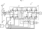
- Fig. 1 is a diagram depicting an example of a configuration of a power conversion device of Example 1 of embodiment.
- the power conversion device 1S includes an input current sensor 101, an input voltage sensor 102, a DC voltage sensor 103, a converter 110, converter SiC-MOSFETs 111 to 114, converter gate drivers 119 to 122, an inverter 130, inverter SiC-MOSFETs 131 to 136, inverter gate drivers 143 to 148, a DC smoothing capacitor 423, a motor 450, an inverter 453 for auxiliary power supply, auxiliary power supply three-phase outputs 454, a circuit breaker 501 for APS, a reactor 502, a backflow preventing diode 503, and a controller 460.
- the SiC-MOSFETs Metal-Oxide-Semiconductor Field-Effect Transistors
- a parasitic diode body diode
- a circulation diode freewheel diode
- the present Example is featured as follows: when supplying electric power to the APS while an electric rolling stock equipped with the power conversion device 1S is at a stop and the converter system is inactive, a turn-on signal is input to the gates of the full SiC-MOSFETs through which current is allowed to flow in a reverse direction; by turning the SiC-MOSFETs on, the current flowing through the parasitic diode of each of the SiC-MOSFETs is reduced; and the power conversion device performs a rectification operation, while preventing the SiC-MOSFET elements from deteriorating.
- the controller 460 When the vehicles come to a stop at a station, the controller 460 is notified of the stop of the vehicles from the cab 164 and deactivates the inverter 130 by turning all the inverter SiC-MOSFETs 131 to 136 off. In turn, the controller 460 deactivates the converter 110 by turning all the converter SiC-MOSFETs 111 to 114 off. Then, the controller 460 causes the mode of the converter 110 to make a transition from "converter mode" to "rectification mode". When the vehicles start to move, the controller 460 is notified of moving of the vehicle from the cab 461 and a transition occurs from "rectification mode" to "converter mode". When a mode transition takes place between "converter mode” to "rectification mode", the power conversion device 1S including the converter 110 may be turned off once before the mode transition to ensure safety.
- converter mode refers to a mode in which AC power is converted to DC power by PWM (Pulse Width Modulation) switching control of the converter SiC-MOSFETs 111 to 114.
- Rectification mode refers to a mode in which AC power is converted to DC power by bridge rectification of the converter SiC-MOSFETs 111 to 114 without exerting switching control of the converter SiC-MOSFETs 111 to 114.
- Formula (2) above can be rewritten as expressed in Formula (3) blow depending on the positive or negative output voltage Es.
- the controller 460 in the present Example controls the converter gate drivers 119 to 122 to turn the SiC-MOSFETs 111 and 114 on and turn the SiC-MOSFETs 112 and 113 off and allows a reverse current to flow through the SiC-MOSFETs 111 and 114.
- the controller 460 controls the converter gate drivers 119 to 122 to turn the SiC-MOSFETs 112 and 113 on and turn the SiC-MOSFETs 111 and 114 off and allows a reverse current to flow through the SiC-MOSFETs 112 and 113.
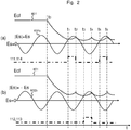
- Fig. 2 is a timing chart representing a relationship between changing of Es and Ecf and gate pulses in Example 1.
- the abscissa of Fig. 2 plots time t and the ordinate plots voltage.
- a label "111, 114" denotes a voltage pulse (gate pulse) that is applied to the gates of the SiC-MOSFETs 111 and 114 and a label "112, 113” denotes a voltage pulse that is applied to the gates of the SiC-MOSFETs 112 and 113.
- which is presented in Fig.
- the DC stage voltage Ecf decreases over time from timing to at which the vehicles come to a stop and the converter has entered "rectification mode" to timing t 1 . Then, as can be seen in Fig. 2(a) , at timing t 1 , Es is ⁇ 0 and Es becomes higher than Ecf, Es > Ecf; therefore, one of the conditions of Formula (3) above is true. Accordingly, the controller 460 controls the converter gate drivers 119 to 122 to turn the SiC-MOSFETs 111 and 114 on and turn the SiC-MOSFETs 112 and 113 off, as can be seen in Fig. 2(a) and Fig. 2(b) .
- the DC stage voltage Ecf decreases again over time from timing t 2 to t 3 .
- Es is ⁇ 0 and -Es becomes higher than Ecf, -Es > Ecf; therefore, one of the conditions of Formula (3) above is true.
- the controller 460 controls the converter gate drivers 119 to 122 to turn the SiC-MOSFETs 112 and 113 on and turn the SiC-MOSFETs 111 and 114 off, as can be seen in Fig. 2(a) and Fig. 2(b) .
- the DC stage voltage Ecf decreases again over time from timing t 4 to t 5 .
- Es is ⁇ 0 and Es becomes higher than Ecf, Es > Ecf; therefore, one of the conditions of Formula (3) above is true.
- the controller 460 controls the converter gate drivers 119 to 122 to turn the SiC-MOSFETs 111 and 114 on and turn the SiC-MOSFETs 112 and 113 off, as can be seen in Fig. 2(a) and Fig. 2(b) .
- the SiC-MOSFETs 111 to 114 can be prevented from deteriorating by conducting current to their parasitic diodes. Also, because the converter can be deactivated when the vehicles are stopping at a station, noise reduction can also be effected. Moreover, because the SiC-MOSFETs can be prevented from deteriorating, there is also an advantage in which system reliability can be improved. Besides, it is possible to realize a power conversion device including a converter that applied SiC-MOSFETs and achieve energy saving of railway vehicles, while achieving it to make the power conversion device smaller and lighter.
- Fig. 3 is a diagram depicting a configuration of a power conversion device of Example 2 of embodiment.
- the same components as those in Fig. 1 and Fig. 5 are assigned the same reference signs.
- the power conversion device 2S of Example 2 includes a converter 210, converter SiC-MOSFETs 201 to 208, clamp diodes 209 to 212, converter gate drivers 213 to 220, DC smoothing capacitors 230 and 231, and DC voltage sensors 232 and 233.
- Converter SiC-MOSFETs 201 and 202 are a set of power semiconductor elements forming a pair of arms.
- Converter SiC-MOSFETs 203 and 204 are also a set of power semiconductor elements forming a pair of arms.
- Converter SiC-MOSFETs 205 and 206 are also a set of power semiconductor elements forming a pair of arms.
- Converter SiC-MOSFETs 207 and 208 are also a set of power semiconductor elements forming a pair of arms.
- the present Example is featured in that the present invention was applied to a three-level converter.
- the output voltage Es of the traction transformer 406 is detected by the input voltage sensor 102.
- the DC stage voltage Ecf is detected by the DC voltage sensors 232 and 233.
- Example 2 As with Example 1, in Example 2, with the converter being placed in "rectification mode", when Es > Ecf is true if the output voltage Es ⁇ 0, as expressed in Formula (3) above, the condition of Formula (2) above is true. Under this situation, by turning the SiC-MOSFETs 201 and 202 and the SiC-MOSFETs 207 and 208 on and turning the SiC-MOSFETs 203 and 204 and the SiC-MOSFETs 205 and 206 off, a reverse current is allowed to flow through the SiC-MOSFETs 201 and 202 and the SiC-MOSFETs 207 and 208.
- the converter may be a multiple-level converter more than three levels.
- the present Example is such that the present invention was applied to a charging current of the DC stage that is generated at startup of the power conversion device 1S or 2S of Example 1 or 2.
- a startup sequence of the power conversion device 1S in Fig. 1 is described below.
- the power collector 401 Before startup of the power conversion device 1S when the vehicles are stopping, the power collector 401 is non-contact with the contact line system and the circuit breaker 405 located at the secondary side of the traction transformer 406 is open.
- the circuit breaker 405 closes and a secondary voltage of the traction transformer 406 is applied to the converter 410.
- the DC stage voltage Ecf is lower than the output voltage Es of the traction transformer 406, the condition of Formula (2) above and one of the conditions of Formula (3) above are true and a reverse current comes to flow through the SiC-MOSFETs.
- power semiconductor elements are SiC-MOSFETs in the foregoing Examples, no limitation to this is intended.
- Those elements may be other wide-gap semiconductor elements having a band gap at or wider than a given value, in which a parasitic diode can be used as a circulation diode, namely, power semiconductor elements using a silicon, gallium nitride, or diamond wafer among others.
- the present invention is not limited to Examples of embodiment described hereinbefore and various modifications are included therein.
- the foregoing Examples are those described in detail to explain the present invention clearly and the invention is not necessarily limited to those including all components described.
- a subset of the components of an Example may be replaced by components of another Example and components of another Example may be added to the components of an Example.
- other components may be added to the subset or the subset may be removed or replaced by other components, and the subset may be united with another Example or separated and deployed to different Examples.
- respective processing steps set forth in an Example may be redeployed or united appropriately based on processing efficiency or implementation efficiency.
- 1S, 2S, 3S, 4S power conversion device
- 102 input voltage sensor
- 401 power collector
- 406 traction transformer
- 453 inverter for auxiliary power supply
- 460 controller
Applications Claiming Priority (2)
| Application Number | Priority Date | Filing Date | Title |
|---|---|---|---|
| JP2018165525 | 2018-09-04 | ||
| PCT/JP2019/012271 WO2020049782A1 (ja) | 2018-09-04 | 2019-03-22 | 電力変換装置及び電力変換方法 |
Publications (3)
| Publication Number | Publication Date |
|---|---|
| EP3849072A1 true EP3849072A1 (de) | 2021-07-14 |
| EP3849072A4 EP3849072A4 (de) | 2022-05-18 |
| EP3849072B1 EP3849072B1 (de) | 2024-03-20 |
Family
ID=69721907
Family Applications (1)
| Application Number | Title | Priority Date | Filing Date |
|---|---|---|---|
| EP19857156.4A Active EP3849072B1 (de) | 2018-09-04 | 2019-03-22 | Leistungsumwandlungsvorrichtung und leistungsumwandlungsverfahren |
Country Status (4)
| Country | Link |
|---|---|
| EP (1) | EP3849072B1 (de) |
| JP (1) | JP7030203B2 (de) |
| CN (1) | CN112219347B (de) |
| WO (1) | WO2020049782A1 (de) |
Family Cites Families (9)
| Publication number | Priority date | Publication date | Assignee | Title |
|---|---|---|---|---|
| JP4537802B2 (ja) * | 2004-08-24 | 2010-09-08 | 株式会社東芝 | 電力変換装置 |
| JP5212303B2 (ja) | 2009-07-31 | 2013-06-19 | ダイキン工業株式会社 | 電力変換装置 |
| EP2590212B1 (de) * | 2010-07-01 | 2015-08-19 | Mitsubishi Electric Corporation | Leistungshalbleitermodul, stromtransformatorvorrichtung und schienenfahrzeug |
| JP5931669B2 (ja) * | 2012-09-21 | 2016-06-08 | 九州旅客鉄道株式会社 | 電気車用電源システム及び電力供給制御方法 |
| JP2015192515A (ja) * | 2014-03-28 | 2015-11-02 | 株式会社日立製作所 | 駆動システム |
| JP6302760B2 (ja) * | 2014-06-13 | 2018-03-28 | 株式会社日立製作所 | 劣化診断機能を有する電力変換装置 |
| CN107078682B (zh) * | 2014-09-02 | 2019-09-10 | 日本精工株式会社 | 电动机控制装置以及搭载了该电动机控制装置的电动助力转向装置和车辆 |
| JP7044462B2 (ja) * | 2016-06-28 | 2022-03-30 | 日立ジョンソンコントロールズ空調株式会社 | 電力変換装置、及びこれを備える空気調和機 |
| CA3039076C (en) * | 2016-10-19 | 2020-03-24 | Imalog Inc. | Hybrid rectifier |
-
2019
- 2019-03-22 EP EP19857156.4A patent/EP3849072B1/de active Active
- 2019-03-22 WO PCT/JP2019/012271 patent/WO2020049782A1/ja unknown
- 2019-03-22 CN CN201980035522.6A patent/CN112219347B/zh active Active
- 2019-03-22 JP JP2020541002A patent/JP7030203B2/ja active Active
Also Published As
| Publication number | Publication date |
|---|---|
| EP3849072B1 (de) | 2024-03-20 |
| EP3849072A4 (de) | 2022-05-18 |
| CN112219347B (zh) | 2024-04-16 |
| CN112219347A (zh) | 2021-01-12 |
| JP7030203B2 (ja) | 2022-03-04 |
| WO2020049782A1 (ja) | 2020-03-12 |
| JPWO2020049782A1 (ja) | 2021-08-12 |
Similar Documents
| Publication | Publication Date | Title |
|---|---|---|
| US8297389B2 (en) | Load driving system and electric vehicle using the system | |
| US9564822B2 (en) | DC power supply device and power conversion method for converting an AC power supply into a DC power supply | |
| CN103125022B (zh) | 功率半导体模块、电力转换装置和铁路车辆 | |
| EP2538543B1 (de) | Stromrichter | |
| US9774215B2 (en) | Power conversion apparatus | |
| US20130038140A1 (en) | Switching circuit | |
| EP3518406A1 (de) | Stromwandlungsvorrichtung | |
| CN111082671B (zh) | 电梯系统中的功率管理 | |
| US20140001988A1 (en) | Electric motor vehicle | |
| JP5288178B2 (ja) | モータ駆動システム | |
| EP3316470A1 (de) | Wechselrichter mit ladefähigkeit | |
| JP2018033214A (ja) | 電源システム | |
| EP3849072B1 (de) | Leistungsumwandlungsvorrichtung und leistungsumwandlungsverfahren | |
| CN111835215A (zh) | 转换器电路、电力转换系统以及电动机驱动装置 | |
| EP2936672B1 (de) | Brückenbein | |
| US20210167683A1 (en) | Voltage Supply Device having an Intermediate Circuit, A Power Converter and Braking Chopper | |
| JPH08168101A (ja) | 電力変換装置 | |
| CN111917358A (zh) | 电气驱动系统和运行方法 | |
| WO2023112220A1 (ja) | 電力変換装置 | |
| WO2022153614A1 (ja) | マルチレベルインバータ | |
| US11394332B2 (en) | Motor driving apparatus and motor driving method | |
| US20220255443A1 (en) | Power conversion apparatus | |
| JP2007074772A (ja) | 電圧変換装置及びその制御方法並びにハイブリッドシステム及びその制御方法 | |
| US10193433B2 (en) | Railway vehicle control apparatus | |
| JP6561768B2 (ja) | 充電共用インバータ、及び充電システム |
Legal Events
| Date | Code | Title | Description |
|---|---|---|---|
| STAA | Information on the status of an ep patent application or granted ep patent |
Free format text: STATUS: THE INTERNATIONAL PUBLICATION HAS BEEN MADE |
|
| STAA | Information on the status of an ep patent application or granted ep patent |
Free format text: STATUS: THE INTERNATIONAL PUBLICATION HAS BEEN MADE |
|
| PUAI | Public reference made under article 153(3) epc to a published international application that has entered the european phase |
Free format text: ORIGINAL CODE: 0009012 |
|
| STAA | Information on the status of an ep patent application or granted ep patent |
Free format text: STATUS: REQUEST FOR EXAMINATION WAS MADE |
|
| 17P | Request for examination filed |
Effective date: 20201215 |
|
| AK | Designated contracting states |
Kind code of ref document: A1 Designated state(s): AL AT BE BG CH CY CZ DE DK EE ES FI FR GB GR HR HU IE IS IT LI LT LU LV MC MK MT NL NO PL PT RO RS SE SI SK SM TR |
|
| DAV | Request for validation of the european patent (deleted) | ||
| DAX | Request for extension of the european patent (deleted) | ||
| RIN1 | Information on inventor provided before grant (corrected) |
Inventor name: KOUNO, YASUHIKO |
|
| A4 | Supplementary search report drawn up and despatched |
Effective date: 20220420 |
|
| RIC1 | Information provided on ipc code assigned before grant |
Ipc: H02M 7/487 20070101ALI20220412BHEP Ipc: H02M 5/458 20060101ALI20220412BHEP Ipc: H02M 7/219 20060101ALI20220412BHEP Ipc: H02M 1/32 20070101ALI20220412BHEP Ipc: B60L 9/26 20060101ALI20220412BHEP Ipc: B60L 1/00 20060101ALI20220412BHEP Ipc: H02M 7/12 20060101AFI20220412BHEP |
|
| GRAP | Despatch of communication of intention to grant a patent |
Free format text: ORIGINAL CODE: EPIDOSNIGR1 |
|
| STAA | Information on the status of an ep patent application or granted ep patent |
Free format text: STATUS: GRANT OF PATENT IS INTENDED |
|
| RIC1 | Information provided on ipc code assigned before grant |
Ipc: H02M 1/00 20060101ALI20230907BHEP Ipc: B60L 9/28 20060101ALI20230907BHEP Ipc: B60L 3/00 20190101ALI20230907BHEP Ipc: H02M 7/487 20070101ALI20230907BHEP Ipc: H02M 5/458 20060101ALI20230907BHEP Ipc: H02M 7/219 20060101ALI20230907BHEP Ipc: H02M 1/32 20070101ALI20230907BHEP Ipc: B60L 9/26 20060101ALI20230907BHEP Ipc: B60L 1/00 20060101ALI20230907BHEP Ipc: H02M 7/12 20060101AFI20230907BHEP |
|
| INTG | Intention to grant announced |
Effective date: 20231002 |
|
| GRAS | Grant fee paid |
Free format text: ORIGINAL CODE: EPIDOSNIGR3 |
|
| GRAA | (expected) grant |
Free format text: ORIGINAL CODE: 0009210 |
|
| STAA | Information on the status of an ep patent application or granted ep patent |
Free format text: STATUS: THE PATENT HAS BEEN GRANTED |
|
| AK | Designated contracting states |
Kind code of ref document: B1 Designated state(s): AL AT BE BG CH CY CZ DE DK EE ES FI FR GB GR HR HU IE IS IT LI LT LU LV MC MK MT NL NO PL PT RO RS SE SI SK SM TR |
|
| REG | Reference to a national code |
Ref country code: GB Ref legal event code: FG4D |
|
| REG | Reference to a national code |
Ref country code: CH Ref legal event code: EP |
|
| REG | Reference to a national code |
Ref country code: DE Ref legal event code: R096 Ref document number: 602019048764 Country of ref document: DE |