EP3848495A1 - Haushaltsgerät zur pflege von wäschestücken mit spezifisch aufgeweitetem spalt zwischen der wäschetrommel und einem laugenbehälter - Google Patents
Haushaltsgerät zur pflege von wäschestücken mit spezifisch aufgeweitetem spalt zwischen der wäschetrommel und einem laugenbehälter Download PDFInfo
- Publication number
- EP3848495A1 EP3848495A1 EP20212971.4A EP20212971A EP3848495A1 EP 3848495 A1 EP3848495 A1 EP 3848495A1 EP 20212971 A EP20212971 A EP 20212971A EP 3848495 A1 EP3848495 A1 EP 3848495A1
- Authority
- EP
- European Patent Office
- Prior art keywords
- gap
- section end
- rotation
- household appliance
- laundry drum
- Prior art date
- Legal status (The legal status is an assumption and is not a legal conclusion. Google has not performed a legal analysis and makes no representation as to the accuracy of the status listed.)
- Granted
Links
Images
Classifications
-
- D—TEXTILES; PAPER
- D06—TREATMENT OF TEXTILES OR THE LIKE; LAUNDERING; FLEXIBLE MATERIALS NOT OTHERWISE PROVIDED FOR
- D06F—LAUNDERING, DRYING, IRONING, PRESSING OR FOLDING TEXTILE ARTICLES
- D06F37/00—Details specific to washing machines covered by groups D06F21/00 - D06F25/00
- D06F37/26—Casings; Tubs
Definitions
- the household appliance has a housing.
- the household appliance has a laundry drum which is arranged in the housing.
- the household appliance also has a tub.
- the tub surrounds the laundry drum viewed in the direction of rotation about an axis of rotation of the laundry drum. In the radial direction to the axis of rotation, a gap is formed between the laundry drum and the tub. Viewed in the direction of rotation around the longitudinal axis, the gap is formed with a varying radial dimension.
- Such a configuration is, for example, from EP 0 844 324 A1 known.
- the radial widening there of the gap that runs completely around the axis of rotation in the direction of rotation is only formed in a lower, very small area.
- water is understood to mean all types of aqueous liquid.
- the object of the present invention is to create a household appliance in which the removal of the water entering the gap from the laundry drum is improved.
- the household appliance has a housing.
- the household appliance has a laundry drum.
- the laundry drum is arranged in the housing.
- the household appliance has a tub separate from the laundry drum.
- the tub surrounds this laundry drum when viewed in the direction of rotation about an axis of rotation of the laundry drum.
- a gap is formed between the laundry drum and the tub.
- the gap is formed with a varying radial dimension when viewed in the direction of rotation around the longitudinal axis.
- the gap has a circumferential section or an azimuthal section which extends over at least 80 ° around the axis of rotation.
- the radial dimension in this specially dimensioned gap increases continuously from a first section end of the gap to a second section end viewed in the direction of rotation around the longitudinal axis.
- a very specific azimuthal width of the gap is thus defined in the household appliance. This is at least 80 °.
- the gap extends in the direction of rotation around the longitudinal axis and thus extends in the azimuthal direction between 80 ° and 120 °, in particular between 80 ° and 100 °, in particular between 85 ° and 95 °, in particular 90 ° .
- angle values in between, in particular in steps of one, are to be viewed as individually disclosed.
- a geometry of the gap in particular a radial dimension of the gap, is changed which enables a continuous reduction in the flow rate of the water present in the gap along the gap extending in this regard.
- This enables the dynamic pressure to be lowered, in particular evenly.
- a geometry, in particular a radial dimension of the gap is selected in which a lowering of this at the second section end of the pressure that is dynamic in a centrifugal operation in the gap by at least 30 percent, particularly preferably by 50 percent, compared to that at the first section end Spin mode setting dynamic pressure is reached. Because of this, the flow of water emerging from the laundry drum at high speed along this gap can be evenly calmed and almost completely calmed at the second end of the section.
- the formation of a water ring is at least minimized as a result, and continuous pumping is possible as a result.
- the geometry of the gap is preferably determined on the basis of the dynamic pressure that is set at the first and second end of the section, which during the spin operation when rotating the laundry drum at a speed that is at least 50% of the maximum operating speed set for the spin operation, in particular is the maximum operating speed.
- the second section end is the end that is subordinate in the flow direction of the water in the gap. This means that the water flows quasi from the first section end to the second section end in the gap.
- the radial dimension at the second section end is between 190 percent and 210 percent, in particular 200 percent, of the radial dimension at the first section end.
- such a, in particular continuous, radial widening of the gap is made possible so that, in an advantageous embodiment, twice the radial thickness of the gap is formed at the second section end compared to the first section end. This is a particularly advantageous embodiment in order to achieve the above-mentioned advantages to a particular degree.
- the first section end is arranged in the 3 o'clock position or the 9 o'clock position. This is also an advantageous embodiment, because due to the intended arrangement of the household appliance, the speed of fall or the weight of the water is already fully effective at the first end of the section. The water entering the gap then no longer has to be guided in a quasi horizontal direction along the outside of the laundry drum, but can flow downwards practically straight away.
- the second section end is arranged in the 6 o'clock position. This is also advantageous in that it enables the above-mentioned, particularly efficient reduction in the dynamic pressure along the gap. This is precisely an embodiment in which this dynamic flow can be almost completely eliminated at the second end of the section.
- a pocket for a radiator of the household appliance is then connected to this second section end. This means that, viewed in the direction of rotation around the longitudinal axis, the gap does not form a partial area of this pocket. The pocket therefore only adjoins this second section end. In particular, it can thus be provided that the exit of the gap forms the entrance of the pocket.
- the entrance is the pocket of the Radiator significantly larger than the radial dimension of the gap at this second end of the section.
- the inlet of the pocket for the heating element in this radial direction is at least twice larger than the radial dimension of the gap at the second end of the section.
- the increase in the radial dimension takes place in the direction of rotation in which the laundry drum is rotated about the axis of rotation. This also benefits the advantages mentioned above.
- the second section end ends at an outlet for the lye water of the tub and / or at a pocket for a heating element of the tub.
- the household appliance has a housing.
- the household appliance has a laundry drum.
- the laundry drum is arranged in the housing.
- the household appliance has a tub separate from the laundry drum. The tub surrounds this laundry drum when viewed in the direction of rotation about an axis of rotation of the laundry drum. In the radial direction to the axis of rotation, a gap is formed between the laundry drum and the tub.
- the gap is formed with varying radial dimensions, viewed in the direction of rotation around the longitudinal axis, starting from a first section end to a second section end.
- the radial dimension is selected in such a way that at the second end of the section a lowering of a dynamic pressure which is established in the gap in a centrifugal operation by at least 30 percent, in particular by 50 percent, compared to that at the first section end is made possible in the spin operation adjusting dynamic pressure.
- the gap preferably has a circumferential section or an azimuthal section with the first section end and the second section end.
- the radial dimension at the second section end is between 190 percent and 210 percent, in particular 200 percent, of the radial dimension at the first section end.
- Embodiments of the household appliance according to the above-mentioned first independent aspect are to be regarded as advantageous embodiments of the second independent aspect mentioned here.
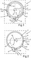
- a household appliance 1 for the care of laundry items is shown in a schematic representation.
- the household appliance 1 is a washing machine or a washer-dryer.
- the household appliance 1 has a housing 2.
- a laundry drum 3 is arranged in the housing 2.
- the laundry drum 3 can be rotated about an axis of rotation A which is oriented perpendicular to the plane of the figure.
- the laundry drum 3 rotates in the spin mode in particular along the arrow P and thus counterclockwise when viewed from the front.
- the household appliance 1 has a tub 4 separate from the laundry drum 3.
- the tub 4 surrounds the washing drum 3 on its jacket wall 5 all the way around.
- the laundry drum 3 is thus received in the tub 4.
- This arrangement is such that a gap 6 is formed between the jacket wall 5 of the laundry drum 3 with the tub 4.
- This gap 6 is designed to run completely around the axis of rotation A in the direction of rotation.
- the household appliance 1 also has a sleeve 7.
- a cuff gap 8 is also formed.
- the household appliance 1 also has a pocket 9 for a radiator.
- the household appliance 1 can also have an outlet 10 for pumping out lye water.
- the gap 6 is specifically designed in a gap area or a circumferential section 11.
- the circumferential section 11, which can also be referred to as an azimuthal section, has a first section end 12.
- this circumferential section 11 has a second section end 13.
- the azimuthal length of this circumferential section 11 is between 80 ° and 100 °, in particular between 85 ° and 95 °, in particular 90 °.
- an advantageous embodiment provides that the first section end 12 is arranged in a 9 o'clock position.
- the second section end 13 is preferably arranged in a 6 o'clock position.
- this circumferential section 11 has a radial dimension which increases continuously from the first section end 12 to the second section end 13.
- this radial dimension which is thus dimensioned perpendicular to the axis of rotation A, in the second section end 13 is between 190 percent and 210 percent, in particular 200 percent, of the radial dimension at the first section end 12. This increase in the radial dimension is particularly linear. This radial dimension increases in the direction of rotation P.
- the radial dimension 12a is dimensioned at the first section end 12 and the radial dimension 13a is dimensioned at the second section end 13.
- the outlet 10 and / or the pocket 9 directly adjoins the second section end 13 in this direction of rotation about the axis of rotation A.
- a radial dimension jump is also formed here.
- the outlet 10 and / or the pocket 9 are designed with a significantly larger radial dimension than the radial dimension 13a at the second section end 13. In particular, an at least doubling is provided here, as it were.
- Fig. 2 is the representation of the essential components in Fig. 1 also shown. In Fig. 2 however, a view along the axis of rotation A from behind onto the household appliance 1 is shown. It can also be seen in the context that a cross flow Q to a radial shaft seal 14 of the household appliance 1 is significantly reduced. The radial shaft seal 14 seals an in Fig. 2 Not shown shaft of the household appliance 1, with which the laundry drum 3 is rotated in the P direction.
Landscapes
- Engineering & Computer Science (AREA)
- Textile Engineering (AREA)
- Detail Structures Of Washing Machines And Dryers (AREA)
- Main Body Construction Of Washing Machines And Laundry Dryers (AREA)
Abstract
Description
- Ein Aspekt der Erfindung betrifft ein Haushaltsgerät zur Pflege von Wäschestücken. Das Haushaltsgerät weist ein Gehäuse auf. Darüber hinaus weist das Haushaltsgerät eine Wäschetrommel auf, die in dem Gehäuse angeordnet ist. Des Weiteren weist das Haushaltsgerät einen Laugenbehälter auf. Der Laugenbehälter umgibt die Wäschetrommel in Umlaufrichtung um eine Drehachse der Wäschetrommel betrachtet. In radialer Richtung zur Drehachse ist zwischen der Wäschetrommel und dem Laugenbehälter ein Spalt ausgebildet. In Umlaufrichtung um die Längsachse betrachtet ist der Spalt mit variierendem Radialmaß ausgebildet. Eine derartige Ausgestaltung ist beispielsweise aus der
EP 0 844 324 A1 bekannt. - Die dortige radiale Aufweitung des in Umlaufrichtung um die Drehachse vollständig umlaufenden Spalts ist nur in einem unteren, sehr kleinen Bereich ausgebildet.
- Beim Schleuderbetrieb des Haushaltsgeräts treten ständig Wasserstrahlen mit relativ hoher Geschwindigkeit aus der Wäschetrommel radial aus. Somit kommt Wasser in den Spalt zwischen Laugenbehälter und Wäschetrommel. Aufgrund der drehenden Wäschetrommel entsteht eine Wasserströmung in dem Spalt. Abhängig von den Drehzahl der Wäschetrommel und den geometrischen Abmessungen des Spaltes stellt sich ein gewisser dynamischer Druck entlang des Spalts zwischen der Wäschetrommel und dem Laugenbehälter ein. Dieser dynamische Druck führt ferner zu einer Reduktion des statischen Drucks im Spalt. Dieser Effekt fördert daher eine weitere ständige Wasserzufuhr zum Spalt bzw. zum im Spalt zirkulierenden Wasserströmung. Dies führt dazu, dass die Wasserströmung mit relativ hoher Geschwindigkeit an einer Tasche für einen Heizkörper des Haushaltsgeräts vorbeiströmt. Diese Wasserströmung dreht sich dann entlang des Strömungskanals bzw. im Spalt weiter im Kreis. Dadurch bildet sich ein Wasserring. Dies erschwert die Entwässerung.
- Bei dem bereits oben genannten Stand der Technik ist dies der Fall. Denn die radiale Aufweitung des Spalts erfolgt nur sehr lokal im Bereich der dort vorgesehenen unteren Tasche für einen Heizkörper. Es ist also nur die Tasche selbst im Wesentlichen aufgeweitet.
- Unter Wasser wird vorliegend sämtliche Art von wässriger Flüssigkeit verstanden.
- Es ist Aufgabe der vorliegenden Erfindung, ein Haushaltsgerät zu schaffen, bei welchem der Abtransport des aus der Wäschetrommel in den Spalt eintretenden Wassers verbessert ist.
- Diese Aufgabe wird durch Haushaltsgeräte gemäß den unabhängigen Ansprüchen gelöst.
- Ein Aspekt der Erfindung betrifft ein Haushaltsgerät zur Pflege von Wäschestücken. Das Haushaltsgerät weist ein Gehäuse auf. Darüber hinaus weist das Haushaltsgerät eine Wäschetrommel auf. Die Wäschetrommel ist in dem Gehäuse angeordnet. Darüber hinaus weist das Haushaltsgerät einen zur Wäschetrommel separaten Laugenbehälter auf. Der Laugenbehälter umgibt in Umlaufrichtung um eine Drehachse der Wäschetrommel betrachtet diese Wäschetrommel. In radialer Richtung zur Drehachse ist zwischen der Wäschetrommel und dem Laugenbehälter ein Spalt ausgebildet. Der Spalt ist in Umlaufrichtung um die Längsachse betrachtet mit variierendem Radialmaß ausgebildet. Der Spalt weist einen Umlaufabschnitt beziehungsweise einen Azimutalabschnitt auf, der sich über zumindest 80° um die Drehachse erstreckt. Das Radialmaß in diesem speziell dimensionierten Spalt ist ausgehend von einem ersten Abschnittende des Spalts bis zu einem in Umlaufrichtung um die Längsachse betrachtet zweiten Abschnittende kontinuierlich zunehmend. Es wird also bei dem Haushaltsgerät eine ganz spezifische azimutale Weite des Spalts definiert. Diese beträgt zumindest 80°.
- Durch ein derartig großes Azimutalintervall des Spalts kann in deutlich verbesserter Art und Weise der im Schleuderbetrieb des Haushaltsgeräts auftretende Wasserstrahl, der aus der Wäschetrommel in den Spalt eintritt, und das im Spalt strömende Wasser verbessert abgeführt werden. Die eingangs genannten Nachteile können dadurch zumindest deutlich reduziert werden. Ein verbessertes Wasserabführmanagement aus dem Spalt ist dadurch ermöglicht.
- In einer vorteilhaften Ausführung ist vorgesehen, dass sich der Spalt in Umlaufrichtung um die Längsachse betrachtet und somit in azimutaler Richtung zwischen 80° und 120°, insbesondere zwischen 80° und 100°, insbesondere zwischen 85° und 95°, insbesondere 90°, erstreckt. Insbesondere sind dazwischenliegende Winkelwerte, insbesondere in Einserschritten, als individuell offenbart anzusehen.
- Bevorzugt wird eine Geometrie des Spalts, insbesondere ein Radialmaß des Spalts verändert, welche eine kontinuierliche Reduzierung der Strömungsgeschwindigkeit des in dem Spalt vorhandenen Wassers entlang des diesbezüglich sich erstreckenden Spalts ermöglicht. Dadurch ist eine, insbesondere gleichmäßige, Absenkung des dynamischen Drucks ermöglicht. Insbesondere wird eine Geometrie, insbesondere ein Radialmaß des Spalts ausgewählt, bei dem eine Absenkung dieses an dem zweiten Abschnittende des sich in einem Schleuderbetrieb im Spalt dynamischen Drucks um zumindest 30 Prozent, besonders bevorzugt um 50 Prozent, gegenüber dem an dem ersten Abschnittende sich bei dem Schleuderbetrieb einstellenden dynamischen Drucks erreicht ist. Aufgrund dessen kann die mit hoher Geschwindigkeit aus der Wäschetrommel austretende Strömung des Wassers entlang dieses Spalts gleichmäßig beruhigt und am zweiten Abschnittende quasi vollständig beruhigt sein. Die Bildung eines Wasserrings, wie dies im Stand der Technik auftritt, ist dadurch zumindest minimiert und ein kontinuierliches Abpumpen ist dadurch ermöglicht.
- Bevorzugt wird die Geometrie des Spalts, insbesondere das Radialmaß, an Hand des sich am ersten und zweiten Abschnittsende einstellenden dynamischen Drucks festgelegt, welcher sich im Schleuderbetrieb beim Drehen der Wäschetrommel mit einer Drehzahl, die mindestens 50% der maximalen für den Schleuderbetrieb festgelegten Betriebsdrehzahl, insbesondere die maximale Betriebsdrehzahl, beträgt. Dies hat den besonderen Vorteil, dass für sämtliche im Schleuderbetrieb auftretenden Drehzahlen der Wäschetrommel die Bildung des Wasserrings zumindest minimiert und ein kontinuierliches Abpumpen ermöglicht wird.
- Insbesondere ist das zweite Abschnittende das in Strömungsrichtung des Wassers in dem Spalt nachrangige Ende. Dies bedeutet, dass das Wasser quasi vom ersten Abschnittende zum zweiten Abschnittende im Spalt strömt. Die vorzugsweise kontinuierliche Aufweitung dieses Spalts in radialer Richtung, wenn man entlang der azimutalen Länge des Spalts wandert, begünstigt die oben genannten Vorteile.
- Vorzugsweise ist vorgesehen, dass das Radialmaß an dem zweiten Abschnittende zwischen 190 Prozent und 210 Prozent, insbesondere 200 Prozent, des Radialmaßes an dem ersten Abschnittende ist. Somit ist in einer vorteilhaften Ausführung eine derartige, insbesondere kontinuierliche, radiale Aufweitung des Spalts ermöglicht, sodass in einer vorteilhaften Ausführung am zweiten Abschnittende die doppelte radiale Dicke des Spalts im Vergleich zum ersten Abschnittende ausgebildet ist. Dies ist eine besonders vorteilhafte Ausführung, um die oben genannten Vorteile in besonderem Maße zu erreichen.
- Vorzugsweise ist vorgesehen, dass das erste Abschnittende in der 3-Uhr-Stellung oder der 9-Uhr-Stellung angeordnet ist. Auch dies ist eine vorteilhafte Ausführung, da aufgrund der bestimmungsgemäßen Anordnung des Haushaltsgeräts dann auch die Fallgeschwindigkeit beziehungsweise die Gewichtskraft des Wassers bereits am ersten Abschnittende voll zur Geltung kommt. Das in den Spalt eintretende Wasser muss dann auch nicht mehr quasi in horizontaler Richtung entlang der Außenseite der Wäschetrommel geführt werden, sondern kann diesbezüglich praktisch gleich vollständig nach unten strömen.
- In einer vorteilhaften Ausführung ist vorgesehen, dass das zweite Abschnittende in der 6-Uhr-Stellung angeordnet ist. Dies ist auch dahingehend vorteilhaft, um die oben genannte, besonders effiziente Reduzierung des dynamischen Drucks entlang des Spalts zu ermöglichen. Gerade dies ist auch eine Ausführung, bei welcher diese dynamische Strömung am zweiten Abschnittende nahezu vollständig eliminiert werden kann. Insbesondere ist vorteilhaft vorgesehen, dass anschließend an dieses zweite Abschnittende eine Tasche für einen Heizkörper des Haushaltsgeräts anschließt. Dies bedeutet, dass in Umlaufrichtung um die Längsachse betrachtet der Spalt keinen Teilbereich dieser Tasche bildet. Die Tasche schließt somit erst an dieses zweite Abschnittende an. Insbesondere kann somit vorgesehen sein, dass der Ausgang des Spalts den Eingang der Tasche bildet. Insbesondere ist vorgesehen, dass an dieser Stelle, an der der Spalt mit seinem zweiten Abschnittende endet, ein diskreter radialer Sprung im Hinblick auf das Radialmaß auftritt. Somit ist der Eingang der Tasche des Heizkörpers deutlich größer als das Radialmaß des Spalts an diesem zweiten Abschnittende. Insbesondere ist der Eingang der Tasche für den Heizkörper in dieser radialen Richtung um zumindest das Doppelte größer als das Radialmaß des Spalts an dem zweiten Abschnittende.
- In vorteilhafter Weise ist vorgesehen, dass die Zunahme des Radialmaßes des Spalts von dem ersten Abschnittende zum zweiten Abschnittende hin linear ist. Auch dadurch können die oben genannten Vorteile verbessert werden.
- Vorzugsweise ist vorgesehen, dass die Zunahme des Radialmaßes in die Drehrichtung erfolgt, in welche die Wäschetrommel um die Drehachse gedreht wird. Auch dadurch ist eine Begünstigung der oben genannten Vorteile erreicht.
- In einer vorteilhaften Ausführung ist vorgesehen, dass das zweite Abschnittende an einem Auslass für das Laugenwasser des Laugenbehälters und/oder an einer Tasche für einen Heizkörper des Laugenbehälters endet. Auch dafür gelten die oben genannten Vorteile. Insbesondere sind auch für den Auslass für das Laugenwasser die vorteilhaften Radialdimensionierungen vorgesehen, wie sie für den Eingang der Tasche für den Heizkörper bereits erläutert wurden.
- Ein weiterer unabhängiger Aspekt der Erfindung betrifft ein Haushaltsgerät zur Pflege von Wäschestücken. Das Haushaltsgerät weist ein Gehäuse auf. Darüber hinaus weist das Haushaltsgerät eine Wäschetrommel auf. Die Wäschetrommel ist in dem Gehäuse angeordnet. Darüber hinaus weist das Haushaltsgerät einen zur Wäschetrommel separaten Laugenbehälter auf. Der Laugenbehälter umgibt in Umlaufrichtung um eine Drehachse der Wäschetrommel betrachtet diese Wäschetrommel. In radialer Richtung zur Drehachse ist zwischen der Wäschetrommel und dem Laugenbehälter ein Spalt ausgebildet. Der Spalt ist in Umlaufrichtung um die Längsachse betrachtet ausgehend von einem ersten Abschnittende bis zu einem zweiten Abschnittende mit variierendem Radialmaß ausgebildet.
- Dabei ist das Radialmaß derart ausgewählt, dass an dem zweiten Abschnittende eine Absenkung eines sich in einem Schleuderbetrieb im Spalt einstellenden dynamischen Drucks um zumindest 30 Prozent, insbesondere um 50 Prozent, gegenüber dem an dem ersten Abschnittende sich bei dem Schleuderbetrieb einstellenden dynamischen Drucks ermöglicht ist. Dies hat die bereits vorstehend aufgeführten Vorteile.
- Bevorzugt weist der Spalt einen Umlaufabschnitt beziehungsweise einen Azimutalabschnitt mit dem ersten Abschnittende und dem zweiten Abschnittende auf. Das Radialmaß an dem zweiten Abschnittende ist zwischen 190 Prozent und 210 Prozent, insbesondere 200 Prozent, des Radialmaßes an dem ersten Abschnittende. Die diesbezüglichen Vorteile wurden bereits oben genannt.
- Ausführungsbeispiele des Haushaltsgeräts gemäß dem oben genannten ersten unabhängigen Aspekt sind als vorteilhafte Ausführungen des hier genannten zweiten unabhängigen Aspekts anzusehen.
- Durch die genannten Haushaltsgeräte ist eine Minimierung der Rückströmung, die insbesondere durch einen Manschettenspalt wieder in die Wäschetrommel zurückströmt, reduziert. Dadurch ist auch eine Reduzierung der Rückbefeuchtung ermöglicht. Ebenso ist eine Reduzierung der Querströmung zu der radialen Wellendichtung des Haushaltsgeräts erreicht. Ebenso wird die Richtung der Querströmung von der Radialwellendichtung umgelenkt. Dadurch ergibt sich eine Verringerung der Belastung der Radialwellendichtung.
- Mit Angaben "oben", "unten", "vorne", "hinten, "horizontal", "vertikal", "Tiefenrichtung", "Breitenrichtung", "Höhenrichtung" etc. sind die bei bestimmungsgemäßen Gebrauch und bestimmungsgemäßem Positionieren der Anordnung gegebenen Positionen und Orientierungen angegeben.
- Weitere Merkmale der Erfindung ergeben sich aus den Ansprüchen, den Figuren und der Figurenbeschreibung. Die vorstehend in der Beschreibung genannten Merkmale und Merkmalskombinationen, sowie die nachfolgend in der Figurenbeschreibung genannten und/oder in den Figuren alleine gezeigten Merkmale und Merkmalskombinationen sind nicht nur in der jeweils angegebenen Kombination, sondern auch in anderen Kombinationen verwendbar, ohne den Rahmen der Erfindung zu verlassen. Es sind somit auch Ausführungen von der Erfindung als umfasst und offenbart anzusehen, die in den Figuren nicht explizit gezeigt und erläutert sind, jedoch durch separierte Merkmalskombinationen aus den erläuterten Ausführungen hervorgehen und erzeugbar sind. Es sind auch Ausführungen und Merkmalskombinationen als offenbart anzusehen, die somit nicht alle Merkmale eines ursprünglich formulierten unabhängigen Anspruchs aufweisen. Es sind darüber hinaus Ausführungen und Merkmalskombinationen, insbesondere durch die oben dargelegten Ausführungen, als offenbart anzusehen, die über die in den Rückbezügen der Ansprüche dargelegten Merkmalskombinationen hinausgehen oder abweichen.
- Ausführungsbeispiele der Erfindung werden nachfolgend anhand schematischer Zeichnungen näher erläutert. Es zeigen:
- Fig. 1
- eine schematische Schnittdarstellung durch Teilkomponenten eines Ausführungsbeispiels eines erfindungsgemäßen Haushaltsgeräts in einer Betrachtung von vorne auf das Haushaltsgerät; und
- Fig. 2
- die Darstellung der Komponenten gemäß
Fig. 1 in einer Betrachtung von hinten auf das Haushaltsgerät. - In
Fig. 1 ist in einer schematischen Darstellung ein Haushaltsgerät 1 zur Pflege von Wäschestücken gezeigt. Das Haushaltsgerät 1 ist eine Waschmaschine oder ein Waschtrockner. Das Haushaltsgerät 1 weist ein Gehäuse 2 auf. In dem Gehäuse 2 ist eine Wäschetrommel 3 angeordnet. Die Wäschetrommel 3 ist um eine Drehachse A, die senkrecht zur Figurenebene orientiert ist, drehbar. Bei der inFig. 1 gezeigten Frontansicht auf das Haushaltsgerät 1 dreht sich die Wäschetrommel 3 im Schleuderbetrieb insbesondere entlang des Pfeils P und somit bei dieser Betrachtung von vorne entgegen dem Uhrzeigersinn. - Darüber hinaus weist das Haushaltsgerät 1 einen zur Wäschetrommel 3 separaten Laugenbehälter 4 auf. Der Laugenbehälter 4 umgibt die Wäschetrommel 3 an deren Mantelwand 5 umlaufend. Die Wäschetrommel 3 ist somit in dem Laugenbehälter 4 aufgenommen. Diese Anordnung ist derart, dass zwischen der Mantelwand 5 der Wäschetrommel 3 mit dem Laugenbehälter 4 ein Spalt 6 ausgebildet ist. Dieser Spalt 6 ist in Umlaufrichtung um die Drehachse A vollständig umlaufend ausgebildet.
- Das Haushaltsgerät 1 weist darüber hinaus auch eine Manschette 7 auf. Es ist auch ein Manschettenspalt 8 gebildet.
- Wie in
Fig. 1 zu erkennen ist, weist das Haushaltsgerät 1 auch eine Tasche 9 für einen Heizkörper auf. Zusätzlich oder anstatt dazu kann das Haushaltsgerät 1 auch einen Auslass 10 zum Abpumpen von Laugenwasser aufweisen. - Wie zu erkennen ist, ist der Spalt 6 in einem Spaltbereich beziehungsweise einem Umlaufabschnitt 11 spezifisch ausgestaltet. Der Umlaufabschnitt 11, der auch als Azimutalabschnitt bezeichnet werden kann, weist ein erstes Abschnittende 12 auf. Darüber hinaus weist dieser Umlaufabschnitt 11 ein zweites Abschnittende 13 auf. Im Ausführungsbeispiel ist vorgesehen, dass die azimutale Länge dieses Umlaufabschnitts 11 zwischen 80° und 100°, insbesondere zwischen 85° und 95°, insbesondere 90°, beträgt. Bei dieser Betrachtung von vorne ist in einer vorteilhaften Ausführung vorgesehen, dass das erste Abschnittende 12 in einer 9-Uhr-Stellung angeordnet ist. Das zweite Abschnittende 13 ist vorzugsweise in einer 6-Uhr-Stellung angeordnet.
- Insbesondere ist vorgesehen, dass dieser Umlaufabschnitt 11 ein Radialmaß aufweist, welches sich ausgehend von dem ersten Abschnittende 12 bis zu dem zweiten Abschnittende 13 kontinuierlich vergrößert. Insbesondere ist vorgesehen, dass dieses Radialmaß, welches somit senkrecht zur Drehachse A bemessen ist, im zweiten Abschnittende 13 zwischen 190 Prozent und 210 Prozent, insbesondere 200 Prozent, des Radialmaßes an dem ersten Abschnittende 12 ist. Diese Zunahme des Radialmaßes ist insbesondere linear. Die Zunahme dieses Radialmaßes erfolgt in Drehrichtung P.
- Das Radialmaß 12a ist an dem ersten Abschnittende 12 bemessen und das Radialmaß 13a an dem zweiten Abschnittende 13 bemessen. Wie darüber hinaus in
Fig. 1 zu erkennen ist, schließt in dieser Umlaufrichtung um die Drehachse A der Auslass 10 und/oder die Tasche 9 direkt an das zweite Abschnittende 13 an. Wie darüber hinaus zu erkennen ist, ist hier auch ein Radialmaßsprung ausgebildet. Der Auslass 10 und/oder die Tasche 9 sind diesbezüglich mit einem deutlich größeren Radialmaß ausgebildet, als das Radialmaß 13a am zweiten Abschnittende 13 ist. Insbesondere ist hier quasi eine zumindest Verdopplung vorgesehen. - Wie darüber hinaus in
Fig. 1 zu erkennen ist, wird durch diese spezifische Ausgestaltung des Umlaufabschnitts 11 eine Rückströmung S durch den Manschettenspalt 8 minimiert. - In
Fig. 2 ist die Darstellung der wesentlichen Komponenten inFig. 1 ebenso gezeigt. InFig. 2 ist allerdings eine Betrachtung entlang der Drehachse A von hinten auf das Haushaltsgerät 1 gezeigt. Ebenso ist in dem Zusammenhang zu erkennen, dass eine Querströmung Q zu einer radialen Wellendichtung 14 des Haushaltsgeräts 1 deutlich reduziert ist. Die radiale Wellendichtung 14 dichtet eine inFig. 2 nicht gezeigte Welle des Haushaltsgeräts 1 ab, mit welcher die Wäschetrommel 3 in Richtung P gedreht wird. -
- 1
- Haushaltsgerät
- 2
- Gehäuse
- 3
- Wäschetrommel
- 4
- Laugenbehälter
- 5
- Mantelwand
- 6
- Spalt
- 7
- Manschette
- 8
- Manschettenspalt
- 9
- Tasche
- 10
- Auslass
- 11
- Umlaufabschnitt
- 12
- erstes Abschnittende
- 12a
- Radialmaß
- 13
- zweites Abschnittende
- 13a
- Radialmaß
- 14
- Wellendichtung
- A
- Drehachse
- P
- Pfeil
- S
- Rückströmung
- Q
- Querströmung
Claims (11)
- Haushaltsgerät (1) zur Pflege von Wäschestücken, mit einem Gehäuse (2), in dem eine Wäschetrommel (3) des Haushaltsgeräts (1) und ein die Wäschetrommel (3) in Umlaufrichtung um eine Drehachse (A) der Wäschetrommel (3) umgebender Laugenbehälter (4) des Haushaltsgeräts (1) angeordnet sind, wobei in radialer Richtung zur Drehachse (A) zwischen der Wäschetrommel (3) und dem Laugenbehälter (4) ein Spalt (6) ausgebildet ist, wobei der Spalt (6) in Umlaufrichtung um die Drehachse (A) betrachtet mit variierendem Radialmaß ausgebildet ist, dadurch gekennzeichnet, dass der Spalt (6) einen Umlaufabschnitt (11) aufweist, der sich über zumindest 80° erstreckt und in welchem das Radialmaß ausgehend von einem ersten Abschnittende (12) bis zu einem zweiten Abschnittende (13) kontinuierlich zunimmt.
- Haushaltsgerät (1) nach Anspruch 1, dadurch gekennzeichnet, dass das Radialmaß (13a) derart ausgewählt ist, dass an dem zweiten Abschnittende (13) eine Absenkung eines sich in einem Schleuderbetrieb im Spalt (6) einstellenden dynamischen Drucks um zumindest 30 Prozent, insbesondere um 50 Prozent, gegenüber dem an dem ersten Abschnittende (12) sich bei dem Schleuderbetrieb einstellenden dynamischen Drucks ermöglicht ist.
- Haushaltsgerät (1) nach Anspruch 1 oder 2, dadurch gekennzeichnet, dass das Radialmaß (13a) an dem zweiten Abschnittende (13) zwischen 190% und 210%, insbesondere 200% des Radialmaßes (12a) an dem ersten Abschnittende (12) ist.
- Haushaltsgerät (1) nach einem der vorhergehenden Ansprüche, dadurch gekennzeichnet, dass das erste Abschnittende (12) in der 3-Uhr-Stellung oder der 9-Uhr-Stellung angeordnet ist.
- Haushaltsgerät (1) nach einem der vorhergehenden Ansprüche, dadurch gekennzeichnet, dass das zweite Abschnittende (13) in der 6-Uhr-Stellung angeordnet ist.
- Haushaltsgerät (1) nach einem der vorhergehenden Ansprüche, dadurch gekennzeichnet, dass die Zunahme des Radialmaßes linear ist.
- Haushaltsgerät (1) nach einem der vorhergehenden Ansprüche, dadurch gekennzeichnet, dass die Zunahme des Radialmaßes in Umlaufrichtung um die Drehachse (A) betrachtet in die Drehrichtung (P) erfolgt, in welche die Wäschetrommel (3) um die Drehachse (A) gedreht wird.
- Haushaltsgerät (1) nach einem der vorhergehenden Ansprüche, dadurch gekennzeichnet, dass das zweite Abschnittende (13) an einem Auslass (10) für das Laugenwasser des Laugenbehälters (4) und/oder an einer Heizkörpertasche (9) des Laugenbehälters (4) endet.
- Haushaltsgerät (1) nach einem der vorhergehenden Ansprüche, dadurch gekennzeichnet, dass sich der Umlaufabschnitt (11) zwischen 80° und 120°, insbesondere zwischen 85° und 95°,erstreckt
- Haushaltsgerät (1) zur Pflege von Wäschestücken, mit einem Gehäuse (2), in dem eine Wäschetrommel (3) des Haushaltsgeräts (1) und ein die Wäschetrommel (3) in Umlaufrichtung um eine Drehachse (A) der Wäschetrommel (3) umgebender Laugenbehälter (4) des Haushaltsgeräts (1) angeordnet sind, wobei in radialer Richtung zur Drehachse (A) zwischen der Wäschetrommel (3) und dem Laugenbehälter (4) ein Spalt (6) ausgebildet ist, wobei der Spalt (6) ausgehend von einem ersten Abschnittende (12) bis zu einem zweiten Abschnittende (13) in Umlaufrichtung um die Drehachse (A) betrachtet mit variierendem Radialmaß ausgebildet ist, dadurch gekennzeichnet, dass das Radialmaß (13a) derart ausgewählt ist, dass an dem zweiten Abschnittende (13) eine Absenkung eines sich in einem Schleuderbetrieb im Spalt (6) einstellenden dynamischen Drucks um zumindest 30 Prozent, insbesondere um 50 Prozent, gegenüber dem an dem ersten Abschnittende (12) sich bei dem Schleuderbetrieb einstellenden dynamischen Drucks ermöglicht ist.
- Haushaltsgerät (1) nach Anspruch 10, dadurch gekennzeichnet, dass der Spalt (6) einen Umlaufabschnitt (11) mit dem ersten Abschnittende (12) und dem zweiten Abschnittende (13) aufweist, wobei das Radialmaß (13a) an dem zweiten Abschnittende (13) zwischen 190% und 210%, insbesondere 200%, des Radialmaßes (12a) an dem ersten Abschnittende (12) ist.
Applications Claiming Priority (1)
| Application Number | Priority Date | Filing Date | Title |
|---|---|---|---|
| DE102020200236.3A DE102020200236A1 (de) | 2020-01-10 | 2020-01-10 | Haushaltsgerät zur Pflege von Wäschestücken mit spezifisch aufgeweitetem Spalt zwischen der Wäschetrommel und einem Laugenbehälter |
Publications (2)
| Publication Number | Publication Date |
|---|---|
| EP3848495A1 true EP3848495A1 (de) | 2021-07-14 |
| EP3848495B1 EP3848495B1 (de) | 2023-11-15 |
Family
ID=73792993
Family Applications (1)
| Application Number | Title | Priority Date | Filing Date |
|---|---|---|---|
| EP20212971.4A Active EP3848495B1 (de) | 2020-01-10 | 2020-12-10 | Haushaltsgerät zur pflege von wäschestücken mit spezifisch aufgeweitetem spalt zwischen der wäschetrommel und einem laugenbehälter |
Country Status (2)
| Country | Link |
|---|---|
| EP (1) | EP3848495B1 (de) |
| DE (1) | DE102020200236A1 (de) |
Citations (3)
| Publication number | Priority date | Publication date | Assignee | Title |
|---|---|---|---|---|
| GB667456A (en) * | 1949-05-13 | 1952-02-27 | John Philip Spencer | Improvements relating to hydro-extractors |
| DE4435095A1 (de) * | 1994-09-30 | 1996-04-04 | Aeg Hausgeraete Gmbh | Waschmaschine mit einem kreisförmigen Laugenbehälter |
| EP0844324A2 (de) | 1996-11-21 | 1998-05-27 | AEG Hausgeräte GmbH | Trommelwaschmaschine |
-
2020
- 2020-01-10 DE DE102020200236.3A patent/DE102020200236A1/de active Pending
- 2020-12-10 EP EP20212971.4A patent/EP3848495B1/de active Active
Patent Citations (3)
| Publication number | Priority date | Publication date | Assignee | Title |
|---|---|---|---|---|
| GB667456A (en) * | 1949-05-13 | 1952-02-27 | John Philip Spencer | Improvements relating to hydro-extractors |
| DE4435095A1 (de) * | 1994-09-30 | 1996-04-04 | Aeg Hausgeraete Gmbh | Waschmaschine mit einem kreisförmigen Laugenbehälter |
| EP0844324A2 (de) | 1996-11-21 | 1998-05-27 | AEG Hausgeräte GmbH | Trommelwaschmaschine |
Also Published As
| Publication number | Publication date |
|---|---|
| EP3848495B1 (de) | 2023-11-15 |
| DE102020200236A1 (de) | 2021-07-15 |
Similar Documents
| Publication | Publication Date | Title |
|---|---|---|
| DE102012202491B3 (de) | Leitrad für eine Impellerpumpe und Impellerpumpe | |
| DE102004011365A1 (de) | Kreiselpumpe | |
| EP2495444A2 (de) | Pumpe | |
| EP2677178A2 (de) | Pumpe | |
| EP0158949B1 (de) | Rotierender Siphon zum Abführen des Kondensats aus einem dampfbeheizten Hohlzylinder | |
| DE4036309A1 (de) | Umfangfluss-brennstoffpumpe | |
| DE102009019401A1 (de) | Fluidleitrohr sowie Welle mit einem Fluidleitrohr | |
| DE102004044345A1 (de) | Luftdüsenspinnvorrichtung | |
| EP2022882A2 (de) | Trommel für eine Waschmaschine und Waschmaschine | |
| EP2481931A2 (de) | Heizeinrichtung für eine Pumpe und Pumpe | |
| DE102015003224B4 (de) | Selbstansaugende Pumpe | |
| EP2451998B1 (de) | Kammelement | |
| EP3848495B1 (de) | Haushaltsgerät zur pflege von wäschestücken mit spezifisch aufgeweitetem spalt zwischen der wäschetrommel und einem laugenbehälter | |
| WO2003014443A1 (de) | Vorrichtung zur herstellung eines gesponnenen garnes | |
| DE102023201351B3 (de) | Mischvorrichtung zum Durchmischen eines Zusatzstoffes mit einer Flüssigkeit in einer Waschmaschine, Waschmaschine und Verfahren | |
| DE1161481B (de) | Einrichtung zur Stabilisierung der Charakteristik von Kreiselradarbeitsmaschinen mit axialdurchstroemtem Laufrad | |
| DE10329612A1 (de) | Garnabzugseinrichtung für Offenend-Spinnvorrichtungen | |
| DE2947941A1 (de) | Waschmaschine mit verbesserter entleerungseinrichtung | |
| EP4324973A1 (de) | Haushaltsgerät zur pflege von wäschestücken mit spezifischem spülsystem für ein luftleitsystem, sowie verfahren | |
| EP3265247B1 (de) | Rotordüse für ein hochdruckreinigungsgerät | |
| WO2025125256A2 (de) | Pumpe und haushaltsgerät mit einer solchen pumpe | |
| DE102004048362A1 (de) | Kreiselpumpe | |
| DE69713064T2 (de) | Rotationsmaschine | |
| WO2025056317A1 (de) | Pumpe und haushaltsgerät mit einer solchen pumpe | |
| DE10346597B3 (de) | Exzenterschnecken-Pumpe mit hoher Standzeit |
Legal Events
| Date | Code | Title | Description |
|---|---|---|---|
| PUAI | Public reference made under article 153(3) epc to a published international application that has entered the european phase |
Free format text: ORIGINAL CODE: 0009012 |
|
| STAA | Information on the status of an ep patent application or granted ep patent |
Free format text: STATUS: THE APPLICATION HAS BEEN PUBLISHED |
|
| AK | Designated contracting states |
Kind code of ref document: A1 Designated state(s): AL AT BE BG CH CY CZ DE DK EE ES FI FR GB GR HR HU IE IS IT LI LT LU LV MC MK MT NL NO PL PT RO RS SE SI SK SM TR |
|
| STAA | Information on the status of an ep patent application or granted ep patent |
Free format text: STATUS: REQUEST FOR EXAMINATION WAS MADE |
|
| 17P | Request for examination filed |
Effective date: 20220114 |
|
| RBV | Designated contracting states (corrected) |
Designated state(s): AL AT BE BG CH CY CZ DE DK EE ES FI FR GB GR HR HU IE IS IT LI LT LU LV MC MK MT NL NO PL PT RO RS SE SI SK SM TR |
|
| GRAP | Despatch of communication of intention to grant a patent |
Free format text: ORIGINAL CODE: EPIDOSNIGR1 |
|
| STAA | Information on the status of an ep patent application or granted ep patent |
Free format text: STATUS: GRANT OF PATENT IS INTENDED |
|
| INTG | Intention to grant announced |
Effective date: 20230707 |
|
| GRAS | Grant fee paid |
Free format text: ORIGINAL CODE: EPIDOSNIGR3 |
|
| GRAA | (expected) grant |
Free format text: ORIGINAL CODE: 0009210 |
|
| STAA | Information on the status of an ep patent application or granted ep patent |
Free format text: STATUS: THE PATENT HAS BEEN GRANTED |
|
| AK | Designated contracting states |
Kind code of ref document: B1 Designated state(s): AL AT BE BG CH CY CZ DE DK EE ES FI FR GB GR HR HU IE IS IT LI LT LU LV MC MK MT NL NO PL PT RO RS SE SI SK SM TR |
|
| REG | Reference to a national code |
Ref country code: CH Ref legal event code: EP Ref country code: GB Ref legal event code: FG4D Free format text: NOT ENGLISH |
|
| REG | Reference to a national code |
Ref country code: DE Ref legal event code: R096 Ref document number: 502020006022 Country of ref document: DE |
|
| REG | Reference to a national code |
Ref country code: IE Ref legal event code: FG4D Free format text: LANGUAGE OF EP DOCUMENT: GERMAN |
|
| REG | Reference to a national code |
Ref country code: LT Ref legal event code: MG9D |
|
| REG | Reference to a national code |
Ref country code: NL Ref legal event code: MP Effective date: 20231115 |
|
| PG25 | Lapsed in a contracting state [announced via postgrant information from national office to epo] |
Ref country code: GR Free format text: LAPSE BECAUSE OF FAILURE TO SUBMIT A TRANSLATION OF THE DESCRIPTION OR TO PAY THE FEE WITHIN THE PRESCRIBED TIME-LIMIT Effective date: 20240216 |
|
| PG25 | Lapsed in a contracting state [announced via postgrant information from national office to epo] |
Ref country code: IS Free format text: LAPSE BECAUSE OF FAILURE TO SUBMIT A TRANSLATION OF THE DESCRIPTION OR TO PAY THE FEE WITHIN THE PRESCRIBED TIME-LIMIT Effective date: 20240315 |
|
| PG25 | Lapsed in a contracting state [announced via postgrant information from national office to epo] |
Ref country code: LT Free format text: LAPSE BECAUSE OF FAILURE TO SUBMIT A TRANSLATION OF THE DESCRIPTION OR TO PAY THE FEE WITHIN THE PRESCRIBED TIME-LIMIT Effective date: 20231115 |
|
| PG25 | Lapsed in a contracting state [announced via postgrant information from national office to epo] |
Ref country code: NL Free format text: LAPSE BECAUSE OF FAILURE TO SUBMIT A TRANSLATION OF THE DESCRIPTION OR TO PAY THE FEE WITHIN THE PRESCRIBED TIME-LIMIT Effective date: 20231115 |
|
| PG25 | Lapsed in a contracting state [announced via postgrant information from national office to epo] |
Ref country code: ES Free format text: LAPSE BECAUSE OF FAILURE TO SUBMIT A TRANSLATION OF THE DESCRIPTION OR TO PAY THE FEE WITHIN THE PRESCRIBED TIME-LIMIT Effective date: 20231115 |
|
| PG25 | Lapsed in a contracting state [announced via postgrant information from national office to epo] |
Ref country code: NL Free format text: LAPSE BECAUSE OF FAILURE TO SUBMIT A TRANSLATION OF THE DESCRIPTION OR TO PAY THE FEE WITHIN THE PRESCRIBED TIME-LIMIT Effective date: 20231115 Ref country code: LT Free format text: LAPSE BECAUSE OF FAILURE TO SUBMIT A TRANSLATION OF THE DESCRIPTION OR TO PAY THE FEE WITHIN THE PRESCRIBED TIME-LIMIT Effective date: 20231115 Ref country code: IS Free format text: LAPSE BECAUSE OF FAILURE TO SUBMIT A TRANSLATION OF THE DESCRIPTION OR TO PAY THE FEE WITHIN THE PRESCRIBED TIME-LIMIT Effective date: 20240315 Ref country code: GR Free format text: LAPSE BECAUSE OF FAILURE TO SUBMIT A TRANSLATION OF THE DESCRIPTION OR TO PAY THE FEE WITHIN THE PRESCRIBED TIME-LIMIT Effective date: 20240216 Ref country code: ES Free format text: LAPSE BECAUSE OF FAILURE TO SUBMIT A TRANSLATION OF THE DESCRIPTION OR TO PAY THE FEE WITHIN THE PRESCRIBED TIME-LIMIT Effective date: 20231115 Ref country code: BG Free format text: LAPSE BECAUSE OF FAILURE TO SUBMIT A TRANSLATION OF THE DESCRIPTION OR TO PAY THE FEE WITHIN THE PRESCRIBED TIME-LIMIT Effective date: 20240215 Ref country code: PT Free format text: LAPSE BECAUSE OF FAILURE TO SUBMIT A TRANSLATION OF THE DESCRIPTION OR TO PAY THE FEE WITHIN THE PRESCRIBED TIME-LIMIT Effective date: 20240315 |
|
| PG25 | Lapsed in a contracting state [announced via postgrant information from national office to epo] |
Ref country code: SE Free format text: LAPSE BECAUSE OF FAILURE TO SUBMIT A TRANSLATION OF THE DESCRIPTION OR TO PAY THE FEE WITHIN THE PRESCRIBED TIME-LIMIT Effective date: 20231115 Ref country code: RS Free format text: LAPSE BECAUSE OF FAILURE TO SUBMIT A TRANSLATION OF THE DESCRIPTION OR TO PAY THE FEE WITHIN THE PRESCRIBED TIME-LIMIT Effective date: 20231115 Ref country code: PL Free format text: LAPSE BECAUSE OF FAILURE TO SUBMIT A TRANSLATION OF THE DESCRIPTION OR TO PAY THE FEE WITHIN THE PRESCRIBED TIME-LIMIT Effective date: 20231115 Ref country code: NO Free format text: LAPSE BECAUSE OF FAILURE TO SUBMIT A TRANSLATION OF THE DESCRIPTION OR TO PAY THE FEE WITHIN THE PRESCRIBED TIME-LIMIT Effective date: 20240215 Ref country code: LV Free format text: LAPSE BECAUSE OF FAILURE TO SUBMIT A TRANSLATION OF THE DESCRIPTION OR TO PAY THE FEE WITHIN THE PRESCRIBED TIME-LIMIT Effective date: 20231115 Ref country code: HR Free format text: LAPSE BECAUSE OF FAILURE TO SUBMIT A TRANSLATION OF THE DESCRIPTION OR TO PAY THE FEE WITHIN THE PRESCRIBED TIME-LIMIT Effective date: 20231115 |
|
| PG25 | Lapsed in a contracting state [announced via postgrant information from national office to epo] |
Ref country code: DK Free format text: LAPSE BECAUSE OF FAILURE TO SUBMIT A TRANSLATION OF THE DESCRIPTION OR TO PAY THE FEE WITHIN THE PRESCRIBED TIME-LIMIT Effective date: 20231115 |
|
| PG25 | Lapsed in a contracting state [announced via postgrant information from national office to epo] |
Ref country code: CZ Free format text: LAPSE BECAUSE OF FAILURE TO SUBMIT A TRANSLATION OF THE DESCRIPTION OR TO PAY THE FEE WITHIN THE PRESCRIBED TIME-LIMIT Effective date: 20231115 |
|
| PG25 | Lapsed in a contracting state [announced via postgrant information from national office to epo] |
Ref country code: SK Free format text: LAPSE BECAUSE OF FAILURE TO SUBMIT A TRANSLATION OF THE DESCRIPTION OR TO PAY THE FEE WITHIN THE PRESCRIBED TIME-LIMIT Effective date: 20231115 |
|
| PG25 | Lapsed in a contracting state [announced via postgrant information from national office to epo] |
Ref country code: SM Free format text: LAPSE BECAUSE OF FAILURE TO SUBMIT A TRANSLATION OF THE DESCRIPTION OR TO PAY THE FEE WITHIN THE PRESCRIBED TIME-LIMIT Effective date: 20231115 Ref country code: SK Free format text: LAPSE BECAUSE OF FAILURE TO SUBMIT A TRANSLATION OF THE DESCRIPTION OR TO PAY THE FEE WITHIN THE PRESCRIBED TIME-LIMIT Effective date: 20231115 Ref country code: RO Free format text: LAPSE BECAUSE OF FAILURE TO SUBMIT A TRANSLATION OF THE DESCRIPTION OR TO PAY THE FEE WITHIN THE PRESCRIBED TIME-LIMIT Effective date: 20231115 Ref country code: IT Free format text: LAPSE BECAUSE OF FAILURE TO SUBMIT A TRANSLATION OF THE DESCRIPTION OR TO PAY THE FEE WITHIN THE PRESCRIBED TIME-LIMIT Effective date: 20231115 Ref country code: EE Free format text: LAPSE BECAUSE OF FAILURE TO SUBMIT A TRANSLATION OF THE DESCRIPTION OR TO PAY THE FEE WITHIN THE PRESCRIBED TIME-LIMIT Effective date: 20231115 Ref country code: DK Free format text: LAPSE BECAUSE OF FAILURE TO SUBMIT A TRANSLATION OF THE DESCRIPTION OR TO PAY THE FEE WITHIN THE PRESCRIBED TIME-LIMIT Effective date: 20231115 Ref country code: CZ Free format text: LAPSE BECAUSE OF FAILURE TO SUBMIT A TRANSLATION OF THE DESCRIPTION OR TO PAY THE FEE WITHIN THE PRESCRIBED TIME-LIMIT Effective date: 20231115 |
|
| REG | Reference to a national code |
Ref country code: CH Ref legal event code: PL |
|
| REG | Reference to a national code |
Ref country code: DE Ref legal event code: R097 Ref document number: 502020006022 Country of ref document: DE |
|
| PG25 | Lapsed in a contracting state [announced via postgrant information from national office to epo] |
Ref country code: LU Free format text: LAPSE BECAUSE OF NON-PAYMENT OF DUE FEES Effective date: 20231210 |
|
| PG25 | Lapsed in a contracting state [announced via postgrant information from national office to epo] |
Ref country code: MC Free format text: LAPSE BECAUSE OF FAILURE TO SUBMIT A TRANSLATION OF THE DESCRIPTION OR TO PAY THE FEE WITHIN THE PRESCRIBED TIME-LIMIT Effective date: 20231115 |
|
| REG | Reference to a national code |
Ref country code: BE Ref legal event code: MM Effective date: 20231231 |
|
| PG25 | Lapsed in a contracting state [announced via postgrant information from national office to epo] |
Ref country code: MC Free format text: LAPSE BECAUSE OF FAILURE TO SUBMIT A TRANSLATION OF THE DESCRIPTION OR TO PAY THE FEE WITHIN THE PRESCRIBED TIME-LIMIT Effective date: 20231115 Ref country code: LU Free format text: LAPSE BECAUSE OF NON-PAYMENT OF DUE FEES Effective date: 20231210 |
|
| PLBE | No opposition filed within time limit |
Free format text: ORIGINAL CODE: 0009261 |
|
| STAA | Information on the status of an ep patent application or granted ep patent |
Free format text: STATUS: NO OPPOSITION FILED WITHIN TIME LIMIT |
|
| REG | Reference to a national code |
Ref country code: IE Ref legal event code: MM4A |
|
| PG25 | Lapsed in a contracting state [announced via postgrant information from national office to epo] |
Ref country code: IE Free format text: LAPSE BECAUSE OF NON-PAYMENT OF DUE FEES Effective date: 20231210 |
|
| PG25 | Lapsed in a contracting state [announced via postgrant information from national office to epo] |
Ref country code: BE Free format text: LAPSE BECAUSE OF NON-PAYMENT OF DUE FEES Effective date: 20231231 |
|
| PG25 | Lapsed in a contracting state [announced via postgrant information from national office to epo] |
Ref country code: FR Free format text: LAPSE BECAUSE OF NON-PAYMENT OF DUE FEES Effective date: 20240115 |
|
| PG25 | Lapsed in a contracting state [announced via postgrant information from national office to epo] |
Ref country code: CH Free format text: LAPSE BECAUSE OF NON-PAYMENT OF DUE FEES Effective date: 20231231 |
|
| 26N | No opposition filed |
Effective date: 20240819 |
|
| PG25 | Lapsed in a contracting state [announced via postgrant information from national office to epo] |
Ref country code: SI Free format text: LAPSE BECAUSE OF FAILURE TO SUBMIT A TRANSLATION OF THE DESCRIPTION OR TO PAY THE FEE WITHIN THE PRESCRIBED TIME-LIMIT Effective date: 20231115 |
|
| PG25 | Lapsed in a contracting state [announced via postgrant information from national office to epo] |
Ref country code: SI Free format text: LAPSE BECAUSE OF FAILURE TO SUBMIT A TRANSLATION OF THE DESCRIPTION OR TO PAY THE FEE WITHIN THE PRESCRIBED TIME-LIMIT Effective date: 20231115 Ref country code: IE Free format text: LAPSE BECAUSE OF NON-PAYMENT OF DUE FEES Effective date: 20231210 Ref country code: FR Free format text: LAPSE BECAUSE OF NON-PAYMENT OF DUE FEES Effective date: 20240115 Ref country code: CH Free format text: LAPSE BECAUSE OF NON-PAYMENT OF DUE FEES Effective date: 20231231 Ref country code: BE Free format text: LAPSE BECAUSE OF NON-PAYMENT OF DUE FEES Effective date: 20231231 |
|
| PG25 | Lapsed in a contracting state [announced via postgrant information from national office to epo] |
Ref country code: FI Free format text: LAPSE BECAUSE OF FAILURE TO SUBMIT A TRANSLATION OF THE DESCRIPTION OR TO PAY THE FEE WITHIN THE PRESCRIBED TIME-LIMIT Effective date: 20231115 |
|
| PG25 | Lapsed in a contracting state [announced via postgrant information from national office to epo] |
Ref country code: CY Free format text: LAPSE BECAUSE OF FAILURE TO SUBMIT A TRANSLATION OF THE DESCRIPTION OR TO PAY THE FEE WITHIN THE PRESCRIBED TIME-LIMIT; INVALID AB INITIO Effective date: 20201210 |
|
| PG25 | Lapsed in a contracting state [announced via postgrant information from national office to epo] |
Ref country code: HU Free format text: LAPSE BECAUSE OF FAILURE TO SUBMIT A TRANSLATION OF THE DESCRIPTION OR TO PAY THE FEE WITHIN THE PRESCRIBED TIME-LIMIT; INVALID AB INITIO Effective date: 20201210 |
|
| GBPC | Gb: european patent ceased through non-payment of renewal fee |
Effective date: 20241210 |
|
| PG25 | Lapsed in a contracting state [announced via postgrant information from national office to epo] |
Ref country code: GB Free format text: LAPSE BECAUSE OF NON-PAYMENT OF DUE FEES Effective date: 20241210 |
|
| PGFP | Annual fee paid to national office [announced via postgrant information from national office to epo] |
Ref country code: AT Payment date: 20260113 Year of fee payment: 5 |
|
| PGFP | Annual fee paid to national office [announced via postgrant information from national office to epo] |
Ref country code: TR Payment date: 20251204 Year of fee payment: 6 |
|
| PGFP | Annual fee paid to national office [announced via postgrant information from national office to epo] |
Ref country code: DE Payment date: 20251231 Year of fee payment: 6 |